EP2172941A1 - Computer apparatus - Google Patents
Computer apparatus Download PDFInfo
- Publication number
- EP2172941A1 EP2172941A1 EP09166742A EP09166742A EP2172941A1 EP 2172941 A1 EP2172941 A1 EP 2172941A1 EP 09166742 A EP09166742 A EP 09166742A EP 09166742 A EP09166742 A EP 09166742A EP 2172941 A1 EP2172941 A1 EP 2172941A1
- Authority
- EP
- European Patent Office
- Prior art keywords
- memory
- program
- unit
- diagnosis
- diagnostic
- Prior art date
- Legal status (The legal status is an assumption and is not a legal conclusion. Google has not performed a legal analysis and makes no representation as to the accuracy of the status listed.)
- Granted
Links
Images


Classifications
-
- G—PHYSICS
- G11—INFORMATION STORAGE
- G11C—STATIC STORES
- G11C29/00—Checking stores for correct operation ; Subsequent repair; Testing stores during standby or offline operation
- G11C29/04—Detection or location of defective memory elements, e.g. cell constructio details, timing of test signals
- G11C29/08—Functional testing, e.g. testing during refresh, power-on self testing [POST] or distributed testing
- G11C29/12—Built-in arrangements for testing, e.g. built-in self testing [BIST] or interconnection details
- G11C29/14—Implementation of control logic, e.g. test mode decoders
- G11C29/16—Implementation of control logic, e.g. test mode decoders using microprogrammed units, e.g. state machines
-
- G—PHYSICS
- G06—COMPUTING OR CALCULATING; COUNTING
- G06F—ELECTRIC DIGITAL DATA PROCESSING
- G06F11/00—Error detection; Error correction; Monitoring
- G06F11/07—Responding to the occurrence of a fault, e.g. fault tolerance
- G06F11/0703—Error or fault processing not based on redundancy, i.e. by taking additional measures to deal with the error or fault not making use of redundancy in operation, in hardware, or in data representation
- G06F11/079—Root cause analysis, i.e. error or fault diagnosis
-
- G—PHYSICS
- G06—COMPUTING OR CALCULATING; COUNTING
- G06F—ELECTRIC DIGITAL DATA PROCESSING
- G06F11/00—Error detection; Error correction; Monitoring
- G06F11/22—Detection or location of defective computer hardware by testing during standby operation or during idle time, e.g. start-up testing
- G06F11/2284—Detection or location of defective computer hardware by testing during standby operation or during idle time, e.g. start-up testing by power-on test, e.g. power-on self test [POST]
-
- G—PHYSICS
- G11—INFORMATION STORAGE
- G11C—STATIC STORES
- G11C29/00—Checking stores for correct operation ; Subsequent repair; Testing stores during standby or offline operation
- G11C29/04—Detection or location of defective memory elements, e.g. cell constructio details, timing of test signals
- G11C2029/0401—Detection or location of defective memory elements, e.g. cell constructio details, timing of test signals in embedded memories
-
- G—PHYSICS
- G11—INFORMATION STORAGE
- G11C—STATIC STORES
- G11C29/00—Checking stores for correct operation ; Subsequent repair; Testing stores during standby or offline operation
- G11C29/04—Detection or location of defective memory elements, e.g. cell constructio details, timing of test signals
- G11C2029/0407—Detection or location of defective memory elements, e.g. cell constructio details, timing of test signals on power on
-
- G—PHYSICS
- G11—INFORMATION STORAGE
- G11C—STATIC STORES
- G11C29/00—Checking stores for correct operation ; Subsequent repair; Testing stores during standby or offline operation
- G11C29/04—Detection or location of defective memory elements, e.g. cell constructio details, timing of test signals
- G11C29/08—Functional testing, e.g. testing during refresh, power-on self testing [POST] or distributed testing
- G11C29/12—Built-in arrangements for testing, e.g. built-in self testing [BIST] or interconnection details
- G11C2029/1208—Error catch memory
Definitions
- the memory diagnosis unit 311 newly diagnoses areas other than the faulty areas determined by the faulty area determination unit 313, of all the areas (1) to (20) of the DRAM 20, by executing a memory diagnostic program 32b that is loaded by the diagnosis program loading unit 314.
- the diagnostic program loading unit 314 and the memory diagnosis unit 311 function as the second memory diagnosis unit, which loads the second memory diagnostic program 32b into one or more of the areas other than the faulty area(s) determined by the faulty area determination unit 313, and executes the second memory diagnostic program 32b.
- the diagnostic program loading unit 314 determines as a loading area or areas, one portion of the areas or part (a subset) of the areas other than the faulty areas determined by the faulty area determination unit 313 at step S15, out of all the areas of the DRAM 20 (step S16), and loads the next memory diagnostic program 32b into the loading areas (step S17).
- the OS error detection unit 315 detects an OS startup error.
- the diagnostic result notification unit 315 notifies the result of the diagnosis by the memory diagnosis unit 311 when the OS error detection unit 315 detects an OS startup error.
- the user can immediately find the faulty areas in the DRAM 20 and take appropriate measures, such as exchanging the faulty areas.
Landscapes
- Engineering & Computer Science (AREA)
- Theoretical Computer Science (AREA)
- General Engineering & Computer Science (AREA)
- Quality & Reliability (AREA)
- Physics & Mathematics (AREA)
- General Physics & Mathematics (AREA)
- Computer Hardware Design (AREA)
- Health & Medical Sciences (AREA)
- Biomedical Technology (AREA)
- Techniques For Improving Reliability Of Storages (AREA)
- For Increasing The Reliability Of Semiconductor Memories (AREA)
- Test And Diagnosis Of Digital Computers (AREA)
Abstract
Description
- The present invention relates to a computer apparatus, and a method of diagnosing (testing) memories.
- Computer apparatuses use many kinds of diagnostic tests that diagnose defective portions of each built-in device. As an example of the computer apparatus, a diagnostic tool is disclosed that runs a memory diagnostic test to diagnose if a memory function in a built-in memory properly works, e.g., if predetermined data can be normally read from and written into the memory. See, for example, Japanese Laid-open Patent Publication No.
H6-4413 - In the simplest diagnostic test, a memory diagnostic program is stored beforehand in one portion of a basic input/output system (BIOS) of the computer apparatus. When the computer apparatus starts up, the memory diagnostic program operates together with the BIOS.
- However, the BIOS usually has a very limited storage capacity, in which another program such as an initial program loader (IPL) is stored. Therefore, the BIOS can contain only a simple memory diagnostic program. Thus, in conventional computer apparatuses, a memory diagnostic program for performing complicated (more complex) memory checking is generally loaded into a main memory such as a random access memory (RAM) by an operating system (OS) and is executed, after the BIOS has operated and the OS has started up.
- Incidentally, conventional computers properly function only if no fault is found in any addresses in the main memory. However, currently, even when some faulty areas are discovered in the main memory by checking the main memory beforehand, a new type of computer apparatus is expected that can run properly by not using the faulty areas.
- To properly run the computer apparatus in spite of the presence of faulty areas in the main memory, the faulty areas need to be detected before the OS starts up.
- However, the memory diagnostic program stored in the BIOS cannot perform a memory diagnosis that allows the OS to properly function.
- The following technique can be considered in this situation. The complicated memory diagnostic program, which was conventionally processed by the OS, is stored in a memory such as a read-only memory (ROM) other than the BIOS. At the same time, a loading program, which loads the complicated memory diagnostic program in predetermined addresses of the main memory, is stored in the BIOS. This enables the complicated memory diagnostic program to be started up when the computer apparatus boots up.
- However, this structure leads to the situation where the memory diagnostic program is loaded into the main memory prior to the memory diagnosis. That is, the memory diagnostic program is loaded into the main memory, while it is unknown whether or not the areas of the main memory, into which the memory diagnostic program is loaded, are faulty. Therefore, there is a possibility that the memory diagnostic program itself cannot be executed.
- The invention is made in view of the problem in the prior art described above. Embodiments of the invention may provide a computer apparatus, a memory diagnosis method and a computer program that can properly execute a memory diagnosis program before the OS starts up, even though the diagnosis program is complicated.
- According to an aspect of the invention, a computer apparatus having a memory includes a first memory diagnosis unit for determining a faulty area in the memory by executing a first memory diagnostic program; a storage unit for storing a relocatable second memory diagnostic program; and a second memory diagnosis unit for loading the second memory diagnostic program into areas of the memory other than the faulty area determined by the first memory diagnosis unit.
- The memory may be a main memory of the computer apparatus, such as the DRAM of a personal computer for example.
- Reference is made, by way of example only, to the accompanying drawings in which:
-
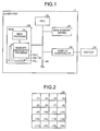
FIG. 1 is a block diagram illustrating a structure of a computer device in accordance with an embodiment of the invention; -
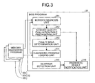
FIG. 2 illustrates the details of a dynamic random access memory (DRAM) ofFIG. 1 ; -
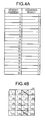
FIG. 3 is a functional block diagram illustrating the details of a BIOS program ofFIG. 1 ; -
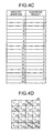
FIG. 4A is a memory-quality evaluation table after amemory diagnostic program 32a has been executed; -
FIG. 4B illustrates an allocated area on the DRAM when amemory diagnostic program 32b is loaded therein; -
FIG. 4C is a memory-quality evaluation table after amemory diagnostic program 32b has been executed; -
FIG. 4D illustrates an allocated area on the DRAM when a memorydiagnostic program 32c is loaded therein; -
FIG. 4E is a memory-quality evaluation table after amemory diagnostic program 32c has been executed; -
FIG. 4F illustrates the result derived by diagnosing the DRAM; and -
FIG. 5 is a flowchart illustrating the procedure of a memory diagnosis process by the computer device in accordance with the embodiment of the invention. - Preferred embodiments of the present invention will be explained with reference to the accompanying drawings.
- The features of a computer apparatus in accordance with the embodiment are described below. The computer apparatus includes a main memory, a first memory diagnostic unit that identifies a faulty or defective area of the main memory by executing a first memory diagnostic program, a storage unit that stores a second memory diagnostic program, which is relocatable, and a second memory diagnostic unit that loads and executes the second memory diagnostic program stored in the storage unit into an area (called the "non-faulty" or "non-defective" area) other than the defective area(s) identified by the first memory diagnosis unit, of the main memory
- That is, the computer apparatus in accordance with the embodiment diagnoses the main memory such as a dynamic random access memory (DRAM) therein, by executing a plurality of memory diagnostic programs.
- Specifically, the storage unit, such as a read only memory (ROM) in the computer apparatus, stores beforehand a plurality of different memory diagnostic programs. The first memory diagnostic unit diagnoses (tests) the main memory, by running the first memory diagnostic program of the plurality of the memory diagnostic programs.
- Each of the plural memory diagnostic programs diagnoses different memory functions and includes a different program size according to the diagnostic level of the memory function. That is, the memory diagnostic program has a larger program size for diagnosis of more advanced memory functions. The first memory diagnostic program belongs to the lowest diagnostic level in the memory function and has the smallest program size.
- The first memory diagnostic unit in accordance with the embodiment executes the first memory diagnostic program, without loading the first memory diagnostic program into the main memory. Thus, a simple diagnosis of the memory function is performed first by the first memory diagnostic unit without using the main memory. Then, a more advanced diagnosis of the memory function is performed by the second memory diagnostic unit. Therefore, at a stage where it is not clear whether or not there is a defective area in the main memory, a memory diagnostic program does not have to be loaded into the main memory. This avoids a situation where the memory diagnostic programs become unexecutable.
- If the first memory diagnostic program is loaded into the main memory to occupy relatively small areas thereon, it may be that the first memory diagnostic unit loads the first memory diagnostic program into the main memory.
- The second memory diagnosis unit loads the second memory diagnostic program stored in the storage unit such as a ROM into areas other than the defective areas in the main memory identified by the first memory diagnosis unit, and executes the second memory diagnostic program. That is, the second memory diagnosis unit excludes one or more defective areas identified by the first memory diagnosis unit from the one or more areas in the main memory for loading the second memory diagnostic program. The defective area is defined as an area, out of all the areas of a main memory, where memory functions such as read and write functions do not work properly. The second memory diagnostic program performs a higher level of diagnosis of memory functions, and is larger in size, than the first memory diagnostic program.
- By doing so, the computer apparatus in accordance with the embodiment can avert a situation where the second diagnostic program is loaded by mistake in a defective area, which cannot properly execute the second diagnostic program.
- The second memory diagnosis unit then diagnoses the main memory again, by executing the second memory diagnosis program that has been loaded into part of the area that is not already identified as defective. Next, the second memory diagnosis unit identifies a new defective area from the areas other than the defective area(s) identified previously, based on the results of the main memory diagnosed by the second memory diagnostic program. Further, the second memory diagnosis unit excludes as defective the newly and previously discovered defective areas from the areas into which the next memory diagnostic programs (i.e., any third memory diagnostic program and any programs thereafter) are to be loaded. These processes are repeated until all of the memory diagnostic programs stored in the storage unit such as a ROM have finished running. Thus, any memory diagnostic programs after the second memory diagnostic program are always loaded into non-faulty areas of the main memory. Thus, the memory diagnostic programs can be properly executed.
- In this way, according to the embodiment, first, the first memory diagnostic program that does not use the main memory or occupies only a small part of the main memory is executed for a simple diagnosis of the main memory. Then, making use of the diagnosis results, a storage location for the second memory diagnostic program, which needs to be loaded into the main memory and can provide a detailed diagnosis of the memory, is identified. Therefore, this reduces the possibility that the second memory diagnostic program and any memory diagnostic programs after the second memory diagnostic program are loaded into the defective areas in the main memory where the memory functions do not properly work and averts a situation where the memory diagnostic programs after the second memory diagnostic program become unexecutable.
- The structure of a computer apparatus in accordance with the embodiment of the invention is explained with reference to
FIG. 1. FIG. 1 is a block diagram illustrating the structure of acomputer apparatus 1 in accordance with the embodiment.FIG. 2 illustrates the details of a DRAM illustrated inFIG. 1 . - As illustrated in
FIG. 1 , thecomputer apparatus 1 includes a central processing unit (CPU) 10, aDRAM 20, aROM 30, adisplay controller 40, and abus 60 that connects the elements described above. - The
CPU 10 controls the overall operation of thecomputer apparatus 1. Specifically, when thecomputer apparatus 1 starts up, theCPU 10 reads a basic input output system (BIOS) program 31 (which will be described later) from theROM 30 and executes theBIOS program 31 to check if there is an error in the devices such asDRAM 20. TheCPU 10 also executes startup of an operating system (OS) and control of various devices by executing theBIOS program 31. - The
DRAM 20 is a main memory (a main storage unit) for thecomputer apparatus 1. Specifically, theDRAM 20 is a device in which the programs (including the BIOS program 31) to be executed by theCPU 10 are loaded, and is used as a working memory to temporarily store various data related to the programs. Furthermore, theDRAM 20, as illustrated inFIG. 2 , is divided into a plurality of areas (1) to (20) in order to load a program to be executed by theCPU 10. - The
ROM 30, functioning as a storage unit, stores data and various programs theCPU 10 executes. The programs theROM 30 stores include theBIOS program 31 and a plurality of memorydiagnostic programs 32. - The
BIOS program 31 is a basic input and output program. Specifically, theBIOS program 31, which starts running when thecomputer apparatus 1 is turned on, is a control program that controls input and output data between the OS and application programs and theDRAM 20 and peripheral devices (display, keyboard, etc.). Moreover, theBIOS program 31 conducts a memory diagnostic process to confirm that data is properly read from and written to theDRAM 20 and that the functions related to a memory protection function and error correction functions properly work. A specific structure by which theBIOS program 31 performs a memory diagnosis process is described below in detail. - The plurality of memory
diagnostic programs 32 is executed when theBIOS program 31 conducts a memory diagnosis process of theDRAM 20 and is a collection of programs to check if various memory functions of theDRAM 20 properly work (e. g. , if predetermined data can properly be written in and read from the memory). In this embodiment, the memorydiagnostic programs 32 include three memorydiagnostic programs diagnostic programs diagnostic program 32a has the lowest diagnostic level of the memory functions and is the smallest in program size of the three memory diagnostic programs. - The
display controller 40 is connected to adisplay 50 and supplies an output such as the result of memory diagnosis of theDRAM 20. Thedisplay 50 is an image display device that visibly shows the output from thedisplay controller 40. - With reference to
FIG. 3 , a specific structure that allows theBIOS program 31 to perform a memory diagnostic process on theDRAM 20 is described in detail.FIG. 3 is a block diagram illustrating the details of theBIOS program 31 ofFIG. 1 and illustrates the functions that can be performed when theBIOS program 31, which is stored in theROM 30, is executed by theCPU 10. - The
BIOS program 31 includes a memorydiagnostic unit 311, a memory-quality evaluation-table preparation unit 312, a faultyarea determination unit 313, a diagnosticprogram loading unit 314, an OSerror detection unit 315, and a diagnosticresult notification unit 316. These functional units 311-316 are executed when theBIOS program 31 starts up (is executed). - The
BIOS program 31, as described above, is executed first when thecomputer apparatus 1 starts up. Thus, the memory diagnostic process of theDRAM 20 is executed before the OS boots up, which enables a memory diagnostic program to run normally even if the OS does not start up. - The
memory diagnosis unit 311 starts diagnosing theDRAM 20 by running the memorydiagnostic program 32a, which is the first memory diagnostic program of the memorydiagnostic programs 32. Furthermore, thememory diagnosis unit 311 runs the memorydiagnostic program 32a without loading the memorydiagnostic program 32a into theDRAM 20. As described above, the memorydiagnostic program 32a contains the lowest diagnostic level for the memory functions and has the smallest program size of the memorydiagnostic programs 32. The program size of the memorydiagnostic program 32a is set to be small, which eliminates the need to load the memorydiagnostic program 32a into theDRAM 20. This can avoid loading the memory diagnostic program into theDRAM 20 when it is unclear whether theDRAM 20 has a defective area. - The memory-quality evaluation-
table preparation unit 312 produces a memory-quality evaluation table that associates the diagnostic results from thememory diagnosis unit 311 with the address information on theDRAM 20. The memory-quality evaluation table will be described below in detail when the procedure of the memory diagnostic process is explained. - The faulty
area determination unit 313 determines faulty or defective areas in theDRAM 20, based on the diagnostic results from thememory diagnosis unit 311. - Specifically, the faulty
area determination unit 313 extracts the address information on theDRAM 20 that is diagnosed as being in error by thememory diagnosis unit 311, referring to the memory-quality evaluation table produced by the memory-quality evaluation-table preparation unit 312, to determine a faulty area in theDRAM 20 based on the extracted address information. In this case, thememory diagnosis unit 311 and the faultyarea determination unit 313 function as a first memory diagnosis unit for determining a faulty area in theDRAM 20, the main memory, by executing the first memorydiagnostic program 32a. - The diagnostic
program loading unit 314 loads the memorydiagnostic program 32b, which is the second memory diagnostic program stored in theROM 30, into the areas other than the faulty areas, which are determined by the faultyarea determination unit 313 for all the areas (1) to (20) of theDRAM 20. To be specific, the diagnosticprogram loading unit 314 extracts the address information of theDRAM 20 that is diagnosed as being in error by thememory diagnosis unit 311, referring to the memory-quality evaluation table prepared by the memory-quality evaluation-table preparation unit 312. Then, the diagnosticprogram loading unit 314 excludes any areas corresponding to the extracted address information as faulty areas, from the areas for loading thememory diagnosis program 32b. In other words, the diagnosticprogram loading unit 314 sets a part (subset) of the areas excluding the or each faulty area as areas for loading the second memorydiagnostic program 32b. - Then, the
memory diagnosis unit 311 newly diagnoses areas other than the faulty areas determined by the faultyarea determination unit 313, of all the areas (1) to (20) of theDRAM 20, by executing a memorydiagnostic program 32b that is loaded by the diagnosisprogram loading unit 314. In this case, the diagnosticprogram loading unit 314 and thememory diagnosis unit 311 function as the second memory diagnosis unit, which loads the second memorydiagnostic program 32b into one or more of the areas other than the faulty area(s) determined by the faultyarea determination unit 313, and executes the second memorydiagnostic program 32b. - Next, based on the result of the new diagnosis by the
memory diagnosis unit 311, the faultyarea determination unit 313 determines one or more new faulty areas, over and above the faulty areas previously determined by the faultyarea determination unit 313, among all the areas (1) to (20) of theDRAM 20. The diagnosticprogram loading unit 314 excludes the faulty areas determined both previously and newly by the faultyarea determining unit 313, as the faulty areas, from a subset of memory areas for loading the memorydiagnostic program 32c that is to be executed next by thememory diagnosis unit 311. - The processes by the functional units 311-314 are repeatedly executed until all of the memory diagnostic programs 32 (32a-32c) are executed by the
memory diagnosis unit 311. Because of this, thememory diagnosis program 32 is always loaded into non-faulty areas rather than known faulty areas of theDRAM 20. Thus, the memory diagnostic program can be properly executed. - The OS
error detection unit 315 detects an error when the OS starts up. Such an OS startup error includes a state in which thecomputer apparatus 1 stops working and does not receive inputs from a keyboard and mouse (known as hung-up), and a state in which the OS itself cannot process continuously (known as blue screen and black screen). When a startup time for thecomputer apparatus 1 in normal operation is measured beforehand, a timeout duration is determined to be stored in a predetermined area of theROM 30, and the hung-up, blue screen, or black screen can be found even after the elapse of the timeout duration, the OSerror detection unit 315 is designed to detect an OS startup error. - When the OS
error detection unit 315 has detected an OS startup error, the diagnosticresult notification unit 316 visually outputs to thedisplay controller 40 the result of the memory diagnosis of theDRAM 20 by thememory diagnosis unit 311. The diagnosticresult notification unit 316 functions as a means for notifying the results of the memory diagnosis of theDRAM 20 by thememory diagnosis unit 311. The testresult notification unit 316 is also configured to output a memory-quality evaluation table prepared by the memory-quality evaluation-table preparation unit 312, as a result of memory diagnosis conducted on theDRAM 20 by thememory diagnosis unit 311. - With reference to
FIGS. 4A to 4F , the procedure as to how theBIOS program 31 performs a memory diagnostic process of theDRAM 20 is specifically described.FIGS. 4A to 4F illustrate the procedure in which theBIOS program 31 executes the memory diagnostic process on theDRAM 20.FIGS. 4A and4C illustrate a memory-quality evaluation table prepared by the memory-quality evaluation-table preparation unit 312 after the memorydiagnostic programs FIGS. 4B and4D illustrate the areas of theDRAM 20, into which the next memorydiagnostic programs program loading unit 314 are to be loaded, respectively. Moreover,FIG. 4E illustrates a memory-quality evaluation table prepared by the memory-quality evaluation-table preparation unit 312 after the memorydiagnostic program 32c is executed, whileFIG. 4F illustrates a final result of the memory diagnosis on theDRAM 20. - As depicted in
FIG. 4A , when the memorydiagnostic program 32a is executed by thememory diagnosis unit 311, a memory-quality evaluation table that associates the results of diagnosis by thememory diagnosis unit 311 with the address information of theDRAM 20 is produced by the memory-quality evaluation-table preparation unit 312. In this case, the memorydiagnostic program 32a is executed by thememory diagnosis unit 311 without being loaded into theDRAM 20. In the memory-quality evaluation table produced by the memory-quality evaluation-table preparation unit 312, numeric value "1" as a result of the memory diagnosis of theDRAM 20 is assigned to the addresses of theDRAM 20 diagnosed as non-faulty by thememory diagnosis unit 311, while numeric value "0" as a result of the memory diagnosis of theDRAM 20 is allocated to the addresses of theDRAM 20 diagnosed as being in error by thememory diagnosis unit 311. InFIG. 4B , the areas (3) and (19), which are assigned "0", are diagnosed as being in error. - Next, as illustrated in
FIG. 4B , the faulty areas in theDRAM 20 are determined by the faultyarea determination unit 313, with reference to the memory-quality evaluation table represented inFIG. 4A . InFIG. 4A , out of all the areas (1) to (20) of theDRAM 20, the areas (3) and (19) that are diagnosed as being in error are determined to be faulty. - As illustrated in
FIG. 4B , part of the areas out of all the areas of theDRAM 20, excluding the faulty areas determined by the faultyarea determination unit 313, are selected by the diagnosticprogram loading unit 314, as areas for loading the memorydiagnostic program 32b that thememory diagnosis unit 311 is to execute next. InFIGs. 4A and 4B , out of all the areas (1) to (20) of theDRAM 20, part of the areas other than the faulty areas (3) and (19) are selected as areas for loading the memorydiagnostic program 32b that is to be executed next. - Next, when the memory
diagnostic program 32b is executed by thememory diagnosis unit 311, areas other than the faulty areas (3) and (19) out of all of theDRAM 20 areas (1) to (20) are newly diagnosed. - As illustrated in
FIG. 4C , the memory-quality evaluation table is updated by the memory-quality evaluation-table preparation unit 312 using the new results of the diagnosis carried out by thememory diagnosis unit 311. That is, in the memory-quality evaluation table, out of all the areas of theDRAM 20, the numeric value "2" as a result of the memory diagnosis is newly assigned to the addresses of the areas that thememory diagnosis unit 311 has newly diagnosed as normal. In contrast, the numeric value "1" as a result of the memory diagnosis is maintained regarding the addresses of areas that thememory diagnosis unit 311 has diagnosed as being in error. InFIGS. 4C and 4D , the areas (5) and (20) to which the numeric value "1" as the memory diagnostic results are assigned, respectively, are newly diagnosed as being in error. - As depicted in
FIG. 4D , new faulty areas out of all the areas (1) to (20) of theDRAM 20, excluding the old faulty areas (3) and (19), are determined by the faultyarea determination unit 313, with reference to the memory-quality evaluation table inFIG. 4C . InFIG. 4C and 4D , the areas (5) and (20) that are newly diagnosed as being in error, out of all the areas (1) to (20) of theDRAM 20, excluding the old faulty areas (3) and (19), are newly determined to be faulty areas. - As illustrated in
FIG. 4D , part of the areas out of all the areas of theDRAM 20, excluding the faulty areas determined by the faultyarea determination unit 313, are newly selected by the diagnosticprogram loading unit 314, as areas for loading the memorydiagnostic program 32c that thememory diagnosis unit 311 is to execute next. InFIGS. 4C and 4D , out of all the areas (1) to (20) of theDRAM 20, part of the areas other than the faulty areas (3), (5), (19) and (20) are newly selected as areas for loading the memorydiagnostic program 32c. - When the memory
diagnostic program 32c is executed by thememory diagnosis unit 311, areas other than the faulty areas (3), (5), (19) and (20) out of all of theDRAM 20 areas (1) to (20) are newly diagnosed. - As illustrated in
FIG. 4E , the memory-quality evaluation table is updated by the memory-quality evaluation-table preparation unit 312, using the new results of the diagnosis carried out by thememory diagnosis unit 311. That is, in the memory-quality evaluation table, out of all the areas of theDRAM 20, the numeric value "3" as a result of the memory diagnosis is newly assigned to the addresses of the areas that thememory diagnosis unit 311 has newly diagnosed as normal. In contrast, the numeric value "2" as a result of the memory diagnosis is maintained regarding the addresses of areas that thememory diagnosis unit 311 has diagnosed as being in error. InFIGS. 4E and 4F , the area (4) to which the numeric value "2" as the memory diagnostic results is assigned are newly diagnosed as being in error. - By executing the processes described above, as illustrated in
FIG. 4F , a final result for the memory diagnosis is obtained that is accordance with the memory diagnosis process executed by theBIOS program 31. - The memory diagnosis process of the
computer apparatus 1 inFIG. 1 is described, with reference toFIG. 5. FIG. 5 is a flowchart illustrating the memory diagnosis process of thecomputer apparatus 1 inFIG. 1 . The memory diagnosis process ofFIG. 5 is a process executed by running theBIOS program 31 theCPU 10 has read out from theROM 30 after thecomputer apparatus 1 is turned on. - As illustrated in
FIG. 5 , thememory diagnosis unit 311 of the BIOS program 31executes the memorydiagnostic program 32a of the memory diagnostic programs 32 (step S10) and tests (diagnoses) all the areas of theDRAM 20 one by one (step S11). Thememory diagnosis unit 311 runs the memorydiagnostic program 32a without loading the memorydiagnostic program 32a into theDRAM 20. Then, thememory diagnosis unit 311 stores into each area of theDRAM 20 the result of the memory diagnosis and the address information of theDRAM 20, both of which are associated with each other (step S12). - Next, the
memory diagnosis unit 311 determines if there is an undiagnosed area present in all the areas of the DRAM 20 (step S13). This determination is based on whether the memory diagnosis results have been associated with the address information of each area of theDRAM 20. If it is determined that an undiagnosed area is present somewhere in the DRAM 20 (step S13; Yes), thememory diagnosis unit 311 repeats the processes of steps S11 to step S13 until there are no undiagnosed areas among all the areas of theDRAM 20. - If it is determined that there are no undiagnosed areas among all the areas of the DRAM 20 (step S13; No), the
memory diagnosis unit 311 requests the memory-quality evaluation-table preparation unit 312 to make a memory-quality evaluation table. Upon receiving the request, the memory-quality evaluation-table preparation unit 312 prepares a memory-quality evaluation table in which the result of the memory diagnosis by thememory diagnosis unit 311 is associated with the address information of the DRAM 20 (step S14), and sends the prepared memory-quality evaluation table to the faultyarea determination unit 313. - Then, referring to the received memory-quality evaluation table, the faulty
area determination unit 313 extracts the address information on theDRAM 20 that is determined to be in error by thememory diagnosis unit 311 to determine a faulty area in theDRAM 20 according to the extracted address information (step S15). - The diagnostic
program loading unit 314 determines as a loading area or areas, one portion of the areas or part (a subset) of the areas other than the faulty areas determined by the faultyarea determination unit 313 at step S15, out of all the areas of the DRAM 20 (step S16), and loads the next memorydiagnostic program 32b into the loading areas (step S17). - Next, the
memory diagnosis unit 311, by executing the loaded memorydiagnostic program 32b (step S18), diagnoses one by one all the areas of theDRAM 20 except for the already-known faulty areas. Then, thememory diagnosis unit 311 stores the result of the memory diagnosis and the address information on theDRAM 20 in each area of theDRAM 20, both of which are associated with each other (step S19). - Then, the
memory diagnosis unit 311 determines if an undiagnosed area is present in the areas other than the faulty areas of all the areas of the DRAM 20 (step S20). If thememory diagnosis unit 311 determines that an undiagnosed area is present (step S20; Yes), thememory diagnosis unit 311 repeats the processes steps S18 to S20 until an undiagnosed area cannot be discovered in the arrears other than the faulty areas of all the areas of theDRAM 20. - Conversely, if the
memory diagnosis unit 311 determines that an undiagnosed area is absent in the areas other than the faulty areas of all the areas of the DRAM 20 (step S20; No), thememory diagnosis unit 311 requests the memory-quality evaluation-table preparation unit 312 to update the memory-quality evaluation table. Upon receiving the request, the memory-quality evaluation-table preparation unit 312 updates the memory-quality evaluation table (step S21). - After that, the
memory diagnosis unit 311 determines if all the memorydiagnostic programs memory diagnosis unit 311 has determined that all the memory diagnostic programs have not been executed (step S22; No), the procedure returns to step S15. Then, the procedures of steps S15 to S22 are repeated until all the memorydiagnostic programs - If the
memory diagnosis unit 311 has determined that all the memory diagnostic programs have been executed (S22; Yes), thememory diagnosis unit 311 proceeds to step S23. - The OS
error detection unit 315 detects if there is an OS error at startup or an OS startup error in step S23. If an OS startup error is detected (S23; Yes) as a result, the OSerror detection unit 315 sends out a detection signal to the diagnosticresult notification unit 316. Upon receiving the detection signal from the OSerror detection unit 315, the diagnosticresult notification unit 316 outputs a memory-quality evaluation table, which is updated by the memory-quality evaluation-table preparation unit 312 in step S21, to thedisplay controller 40 as a result of the memory diagnosis of theDRAM 20. Subsequently, the memory-quality evaluation table is shown on the display 50 (step S24), which ends the memory diagnosis process. In contrast, if an OS startup error is not detected (step S23; No), the OSerror detection unit 315 finishes the memory diagnosis process. - As described above, in this embodiment, the
memory diagnosis unit 311 executes the memorydiagnostic program 32a, the first memory diagnostic program, to diagnose theDRAM 20. The faultyarea determination unit 313 determines the faulty areas in theDRAM 20, based on the diagnosis result by thememory diagnosis unit 311. The memorydiagnostic unit 311 and the faultyarea determination unit 313 function as the first memory diagnosis unit. In addition, the diagnosticprogram loading unit 314 loads the memorydiagnostic program 32b, which will be executed next by thememory diagnosis unit 311, into part of the areas of theDRAM 20 excluding the faulty areas so far determined. Thememory diagnosis unit 311 newly diagnoses, by executing the memorydiagnostic program 32b loaded by the diagnosticprogram loading unit 314, the areas of theDRAM 20 other than the faulty areas determined by the faultyarea determination unit 313. The diagnosticprogram loading unit 314 and the memorydiagnostic unit 311 function as the second memory diagnostic unit. Therefore, the embodiment can avoid loading a memory diagnostic program into the faulty areas, where memory function does not properly work, of the main memory, which prevents the situation occurring where a memory diagnostic program cannot be executed properly. - Furthermore, the
memory diagnosis unit 311, which functions as the first memory diagnosis unit, runs the memorydiagnostic program 32a without loading thememory program 32a into theDRAM 20. Thus, where it is not certain that the main memory contains a faulty area, the memory diagnostic program does not have to be loaded into the main memory. This can avoid the situation where a memory diagnostic program cannot be executed properly. - As a result, an embodiment of the present invention simplifies the determination of the healthy areas and the faulty areas, which leads to a highly efficient memory diagnostic process. Since the memory-quality evaluation-
table preparation unit 312 prepares a memory-quality evaluation table that has associated the result of the memory diagnosis by thememory diagnosis unit 311 with the address information on theDRAM 20, an easy distinction between a faulty area and an area other than a faulty area can be made. This enables a higher efficiency of the memory diagnosis process. - The faulty
area determination unit 313, which functions as the second memory diagnosis unit, extracts the address information on the areas of theDRAM 20 diagnosed as being in error by thememory diagnosis unit 311. An area corresponding to the extracted address information is excluded as faulty from the areas of theDRAM 20 for loading the second memorydiagnostic program 32b. As a result, an easy distinction between a faulty area and an area other than the faulty area leads to an easy determination of the faulty area, which enables a higher efficiency of the memory diagnosis process. - The OS
error detection unit 315 detects an OS startup error. The diagnosticresult notification unit 315 notifies the result of the diagnosis by thememory diagnosis unit 311 when the OSerror detection unit 315 detects an OS startup error. As a result, since a user can confirm the results of the diagnosis by thememory diagnosis unit 311, the user can immediately find the faulty areas in theDRAM 20 and take appropriate measures, such as exchanging the faulty areas. - Each of the
functional units 311 to 316, which starts up when power is turned on, is incorporated into theBIOS program 31 that controls data to be input to and output from theDRAM 20. Moreover, the functional units are executed when theBIOS program 31 starts up. Therefore, before the OS starts up, the memory diagnostic process for theDRAM 20 can be executed. Even if the OS does not start up, a memory diagnostic program can be properly executed. - The embodiments in accordance with the invention are described so far. The invention can cover various, distinct embodiments other than those described above, within the range of the ideas disclosed in the claims.
- For example, in the embodiment the first memory diagnostic program can be executed without being loaded into the main memory by the first memory diagnosis unit. This is not the only single embodiment. The invention also covers the following embodiment. A first memory diagnostic program, which occupies a smaller area, when loaded into a main memory, is loaded into the main memory by a first memory diagnostic unit. By doing so, a simple diagnosis of the main memory may be executed first. In this case, using the result of the diagnosis by the first memory diagnosis unit, a second and a third memory diagnostic program, which occupy larger areas when loaded into the main memory, are loaded into the main memory successively by a second and a third memory diagnostic unit, respectively. This enables the diagnosis of advanced memory functions.
- In the embodiment, the memory diagnosis process that diagnoses the DRAM, a main memory, is described. This is not the only single embodiment. The invention covers the following embodiment. The memory diagnosis process for diagnosing a cache memory that is provided inside a CPU and is capable of high speed writing and reading can be applied.
- The
BIOS program 31 and the memorydiagnostic program 32 of the embodiment do not necessarily have to be stored in theROM 30. For example, these programs may be stored in a re-writable, non-volatile memory such as a flash memory and can be read out and executed by theCPU 10. Also, theBIOS program 31 and thememory diagnosis program 32 may be downloaded to a flash memory from a network-connected server. Moreover, the programs may be stored in a storage medium such as a CD-ROM and be read into a flash memory from the storage medium through a drive thereof. - The term "computer apparatus" in this specification includes not only general-purpose apparatuses such as personal computers but any form of information processing equipment including telecommunications receivers, audio-visual equipment and the like where it is required to load an OS into a memory upon start-up.
- According to the embodiment of the invention, the first memory diagnostic program, which does not use the main memory or occupies only a small portion of the main memory, is executed in order to perform a simple diagnosis of the main memory. Making use of the results of the diagnosis, the second diagnostic program, which needs to be loaded into the main memory and is capable of performing a detailed diagnosis, can be identified with respect to an arrangement location thereof. Consequently, the embodiment can reduce the possibility that the second memory diagnostic program is loaded into faulty areas in the main memory and can avoid a situation where the second memory diagnostic program cannot be executed.
Claims (14)
- A computer apparatus (1) including a memory (20), comprising:a first memory diagnosis unit (311, 313) for determining a faulty area in the memory by executing a first memory diagnostic program (32a);a storage unit (30) for storing a relocatable second memory diagnostic program (32b); anda second memory diagnosis unit (311, 314) for loading the second memory diagnostic program (32b) into an area of the memory (20) other than the faulty area determined by the first memory diagnosis unit.
- The computer apparatus according to claim 1, wherein the first memory diagnostic unit executes the first memory diagnosis program, the first memory diagnosis program not being loaded into the memory.
- The computer apparatus according to claim 1 or 2, further comprising a memory-quality evaluation-table preparation unit (312) for preparing a memory-quality evaluation table in which a result of the diagnosis of the memory by the first memory diagnosis unit is associated with address information of the memory.
- The computer apparatus according to claim 3, wherein the second memory diagnosis unit extracts address information on the memory that is diagnosed as being an error by the first memory diagnosis unit, with reference to the memory-quality evaluation table, and excludes as the faulty area an area corresponding to the extracted address information from areas for loading the second memory diagnostic program.
- The computer apparatus according to any of claims 1 to 4, wherein the memory is a main memory of the computer apparatus, the computer apparatus further comprising:an operating system (OS) error detection unit (315) for detecting an error at a startup of an OS; anda diagnostic result notification unit (316) for notifying a result of diagnosis of the main memory by the second memory diagnosis unit when the OS error detection unit has detected the startup error.
- The computer apparatus according to claim 5, wherein each of the first memory diagnosis unit, the second memory diagnosis unit, the memory-quality evaluation-table preparation unit, the OS error detection unit, and the diagnostic result notification unit, which is incorporated in a basic input and output program that is a control program for controlling data to be input to and output from the main memory, starts up when power is turned on, and becomes in execution when the basic input and output program has started up.
- A method of diagnosing a memory in a computer apparatus, comprising:determining a faulty area in the memory by executing a first memory diagnostic program; andloading a second memory diagnostic program into areas of the memory other than the faulty area determined by the determining of the faulty area.
- The method according to claim 7, wherein the determining of the faulty area executes the first memory diagnosis program without being loaded into the memory.
- The method according to claim 7 or 8, further comprising preparing a memory-quality evaluation table in which a result of the diagnosis of the memory by the determining of the faulty area is associated with address information of the memory.
- The method according to claim 9, wherein the loading of the second memory diagnostic program extracts address information on the memory that is diagnosed as being an error by the determining of the faulty area, with reference to the memory-quality evaluation table, and excludes as the faulty area an area corresponding to the extracted address information from areas for loading of the second memory diagnostic program.
- The method according to any one of claims 7 to 10, applied to a memory which is a main memory of a computer apparatus, and further comprising:starting up an operating system (OS) of the computer apparatus;detecting an error at a startup of the OS; andnotifying a result of diagnosis of the main memory by the loading of the second memory diagnostic program when the detecting of the error has detected the startup error.
- The method according to claim 11, wherein each of the determining of the faulty area, the loading of the second memory diagnostic program, the preparing of the memory-quality evaluation table, the detecting of the startup error, and the notifying of the result of diagnosis, which is incorporated in a basic input and output program that is a control program for controlling data to be input to and output from the main memory, starts up when power is turned on, and becomes in execution when the basic input and output program has started up.
- A computer program which, when run by a computer apparatus, causes the computer apparatus to execute the method according to any one of claims 7 to 12.
- A computer-readable medium on which is stored the computer program according to claim 13.
Applications Claiming Priority (1)
| Application Number | Priority Date | Filing Date | Title |
|---|---|---|---|
| JP2008258974A JP5293062B2 (en) | 2008-10-03 | 2008-10-03 | Computer apparatus, memory diagnosis method, and memory diagnosis control program |
Publications (2)
| Publication Number | Publication Date |
|---|---|
| EP2172941A1 true EP2172941A1 (en) | 2010-04-07 |
| EP2172941B1 EP2172941B1 (en) | 2012-07-11 |
Family
ID=41467428
Family Applications (1)
| Application Number | Title | Priority Date | Filing Date |
|---|---|---|---|
| EP09166742A Not-in-force EP2172941B1 (en) | 2008-10-03 | 2009-07-29 | Computer comprising memory diagnosis units |
Country Status (6)
| Country | Link |
|---|---|
| US (1) | US8510611B2 (en) |
| EP (1) | EP2172941B1 (en) |
| JP (1) | JP5293062B2 (en) |
| KR (1) | KR101025526B1 (en) |
| CN (1) | CN101714112B (en) |
| TW (1) | TWI420312B (en) |
Families Citing this family (8)
| Publication number | Priority date | Publication date | Assignee | Title |
|---|---|---|---|---|
| US7895483B2 (en) * | 2007-05-25 | 2011-02-22 | International Business Machines Corporation | Software memory leak analysis using memory isolation |
| US8266454B2 (en) * | 2009-04-15 | 2012-09-11 | GM Global Technology Operations LLC | Secure flash memory using error correcting code circuitry |
| US8683277B1 (en) * | 2010-07-13 | 2014-03-25 | Marvell International Ltd. | Defect detection using pattern matching on detected data |
| WO2014118910A1 (en) * | 2013-01-30 | 2014-08-07 | 三菱電機株式会社 | Memory diagnosis device |
| CN104123232A (en) * | 2013-04-25 | 2014-10-29 | 宏碁股份有限公司 | Computer system and control method |
| JP2017122997A (en) * | 2016-01-06 | 2017-07-13 | 富士通株式会社 | Information processing unit, control method for arithmetic processing unit, and control program for arithmetic processing unit |
| CN111459572B (en) * | 2020-03-31 | 2023-01-31 | 深圳市汇顶科技股份有限公司 | Program loading method, controller, chip and electronic equipment |
| US20220083252A1 (en) * | 2020-09-14 | 2022-03-17 | Micron Technology, Inc. | Indication-based avoidance of defective memory cells |
Citations (6)
| Publication number | Priority date | Publication date | Assignee | Title |
|---|---|---|---|---|
| US4873705A (en) * | 1988-01-27 | 1989-10-10 | John Fluke Mfg. Co., Inc. | Method of and system for high-speed, high-accuracy functional testing of memories in microprocessor-based units |
| EP0442651A2 (en) * | 1990-02-14 | 1991-08-21 | International Business Machines Corporation | Apparatus and method for background memory test during system start up |
| JPH064413A (en) | 1992-06-18 | 1994-01-14 | Fujitsu Ltd | Memory test control method |
| JPH07191856A (en) * | 1993-12-27 | 1995-07-28 | Toshiba Corp | Information processing equipment |
| US5539878A (en) * | 1995-06-16 | 1996-07-23 | Elonex Technologies, Inc. | Parallel testing of CPU cache and instruction units |
| US20040215952A1 (en) * | 2003-04-24 | 2004-10-28 | Fujitsu Limited | Apparatus, method and recording medium for starting up data processing system |
Family Cites Families (21)
| Publication number | Priority date | Publication date | Assignee | Title |
|---|---|---|---|---|
| US4953165A (en) * | 1988-06-06 | 1990-08-28 | Southwestern Computer Technologies, Inc. | Diagnostic system for personal computer |
| JPH02242439A (en) * | 1989-03-16 | 1990-09-26 | Nec Corp | Program load control system |
| JPH05298140A (en) * | 1992-04-20 | 1993-11-12 | Shikoku Nippon Denki Software Kk | Self-diagnostic system |
| TW272270B (en) * | 1992-08-28 | 1996-03-11 | Compaq Computer Corp | |
| US6076142A (en) * | 1996-03-15 | 2000-06-13 | Ampex Corporation | User configurable raid system with multiple data bus segments and removable electrical bridges |
| JP3017080B2 (en) * | 1996-03-27 | 2000-03-06 | 甲府日本電気株式会社 | Computer system |
| US5793943A (en) * | 1996-07-29 | 1998-08-11 | Micron Electronics, Inc. | System for a primary BIOS ROM recovery in a dual BIOS ROM computer system |
| JPH11144494A (en) * | 1997-11-12 | 1999-05-28 | Nec Corp | Semiconductor memory |
| TW463175B (en) | 2000-03-01 | 2001-11-11 | Winbond Electronics Corp | Memory processing method and system |
| TWI240864B (en) * | 2001-06-13 | 2005-10-01 | Hitachi Ltd | Memory device |
| JP2003288215A (en) * | 2002-03-28 | 2003-10-10 | Mitsubishi Electric Corp | Information processing equipment |
| US7418574B2 (en) * | 2002-10-31 | 2008-08-26 | Lockheed Martin Corporation | Configuring a portion of a pipeline accelerator to generate pipeline date without a program instruction |
| US7328380B2 (en) * | 2003-09-11 | 2008-02-05 | Hewlett-Packard Development Company, L.P. | Memory scrubbing logic |
| JP4292977B2 (en) * | 2003-12-17 | 2009-07-08 | 富士通株式会社 | Controller and computer with memory test function |
| US7266727B2 (en) * | 2004-03-18 | 2007-09-04 | International Business Machines Corporation | Computer boot operation utilizing targeted boot diagnostics |
| KR100922409B1 (en) * | 2005-03-24 | 2009-10-16 | 후지쯔 가부시끼가이샤 | Information processing device and memory anomaly monitoring method |
| US7478281B2 (en) | 2005-06-06 | 2009-01-13 | Denniston William B | System and methods for functional testing of embedded processor-based systems |
| JP4918824B2 (en) * | 2006-08-18 | 2012-04-18 | 富士通株式会社 | Memory controller and memory control method |
| JP5509568B2 (en) * | 2008-10-03 | 2014-06-04 | 富士通株式会社 | Computer apparatus, processor diagnosis method, and processor diagnosis control program |
| TW201020779A (en) * | 2008-11-18 | 2010-06-01 | Inventec Corp | System for auto-operating backup firmware and method thereof |
| US8046631B2 (en) * | 2009-04-29 | 2011-10-25 | Lsi Corporation | Firmware recovery in a raid controller by using a dual firmware configuration |
-
2008
- 2008-10-03 JP JP2008258974A patent/JP5293062B2/en not_active Expired - Fee Related
-
2009
- 2009-07-28 US US12/510,426 patent/US8510611B2/en not_active Expired - Fee Related
- 2009-07-29 EP EP09166742A patent/EP2172941B1/en not_active Not-in-force
- 2009-07-30 TW TW098125685A patent/TWI420312B/en not_active IP Right Cessation
- 2009-09-01 CN CN200910170643.XA patent/CN101714112B/en not_active Expired - Fee Related
- 2009-09-09 KR KR1020090084969A patent/KR101025526B1/en not_active Expired - Fee Related
Patent Citations (6)
| Publication number | Priority date | Publication date | Assignee | Title |
|---|---|---|---|---|
| US4873705A (en) * | 1988-01-27 | 1989-10-10 | John Fluke Mfg. Co., Inc. | Method of and system for high-speed, high-accuracy functional testing of memories in microprocessor-based units |
| EP0442651A2 (en) * | 1990-02-14 | 1991-08-21 | International Business Machines Corporation | Apparatus and method for background memory test during system start up |
| JPH064413A (en) | 1992-06-18 | 1994-01-14 | Fujitsu Ltd | Memory test control method |
| JPH07191856A (en) * | 1993-12-27 | 1995-07-28 | Toshiba Corp | Information processing equipment |
| US5539878A (en) * | 1995-06-16 | 1996-07-23 | Elonex Technologies, Inc. | Parallel testing of CPU cache and instruction units |
| US20040215952A1 (en) * | 2003-04-24 | 2004-10-28 | Fujitsu Limited | Apparatus, method and recording medium for starting up data processing system |
Also Published As
| Publication number | Publication date |
|---|---|
| TWI420312B (en) | 2013-12-21 |
| CN101714112A (en) | 2010-05-26 |
| JP2010092125A (en) | 2010-04-22 |
| TW201015324A (en) | 2010-04-16 |
| KR101025526B1 (en) | 2011-04-04 |
| EP2172941B1 (en) | 2012-07-11 |
| KR20100038137A (en) | 2010-04-13 |
| US8510611B2 (en) | 2013-08-13 |
| US20100088558A1 (en) | 2010-04-08 |
| JP5293062B2 (en) | 2013-09-18 |
| CN101714112B (en) | 2013-05-01 |
Similar Documents
| Publication | Publication Date | Title |
|---|---|---|
| EP2172941B1 (en) | Computer comprising memory diagnosis units | |
| JP5509568B2 (en) | Computer apparatus, processor diagnosis method, and processor diagnosis control program | |
| US7895483B2 (en) | Software memory leak analysis using memory isolation | |
| US20100083250A1 (en) | Virtual machine system, and method for managing thereof | |
| EP2463779A1 (en) | Reset method and monitor | |
| US7631224B2 (en) | Program, method, and mechanism for taking panic dump | |
| CN113721144A (en) | Motor aging test method and device, storage medium and electronic equipment | |
| US20080010567A1 (en) | Memory testing | |
| CN100543693C (en) | Self-detection method for starting up | |
| US20050033952A1 (en) | Dynamic scheduling of diagnostic tests to be performed during a system boot process | |
| CN109086162B (en) | Memory diagnosis method and device | |
| US7613952B2 (en) | Method for facilitating BIOS testing | |
| JP5751626B2 (en) | Memory test apparatus, memory test method, and memory test program | |
| CN102792383A (en) | Method for checking the functionality of a memory element | |
| DE112010005898T5 (en) | A method and system for performing system maintenance in a computing device | |
| JP5348120B2 (en) | Program, method and mechanism for collecting panic dump | |
| JP7426269B2 (en) | Information processing equipment and information processing system | |
| TW201928669A (en) | Computer apparatus, diagnostic method and non-transitory computer-readable storage medium | |
| CN117637009A (en) | Method for starting firmware code through additional boot point | |
| CN118057191A (en) | Pin testing method, device, equipment, medium and product of communication module | |
| CN121148459A (en) | Chip storage area testing methods, apparatus, equipment, and computer storage media | |
| JP2007241839A (en) | Digital signal processing apparatus and failure abnormality information storage method | |
| JPH01136259A (en) | Information processor |
Legal Events
| Date | Code | Title | Description |
|---|---|---|---|
| PUAI | Public reference made under article 153(3) epc to a published international application that has entered the european phase |
Free format text: ORIGINAL CODE: 0009012 |
|
| AK | Designated contracting states |
Kind code of ref document: A1 Designated state(s): AT BE BG CH CY CZ DE DK EE ES FI FR GB GR HR HU IE IS IT LI LT LU LV MC MK MT NL NO PL PT RO SE SI SK SM TR |
|
| AX | Request for extension of the european patent |
Extension state: AL BA RS |
|
| RTI1 | Title (correction) |
Free format text: COMPUTER COMPRISING MEMORY DIAGNOSIS UNITS |
|
| 17P | Request for examination filed |
Effective date: 20101006 |
|
| GRAP | Despatch of communication of intention to grant a patent |
Free format text: ORIGINAL CODE: EPIDOSNIGR1 |
|
| GRAS | Grant fee paid |
Free format text: ORIGINAL CODE: EPIDOSNIGR3 |
|
| GRAA | (expected) grant |
Free format text: ORIGINAL CODE: 0009210 |
|
| AK | Designated contracting states |
Kind code of ref document: B1 Designated state(s): AT BE BG CH CY CZ DE DK EE ES FI FR GB GR HR HU IE IS IT LI LT LU LV MC MK MT NL NO PL PT RO SE SI SK SM TR |
|
| REG | Reference to a national code |
Ref country code: GB Ref legal event code: FG4D |
|
| REG | Reference to a national code |
Ref country code: CH Ref legal event code: EP |
|
| REG | Reference to a national code |
Ref country code: AT Ref legal event code: REF Ref document number: 566482 Country of ref document: AT Kind code of ref document: T Effective date: 20120715 |
|
| REG | Reference to a national code |
Ref country code: IE Ref legal event code: FG4D |
|
| REG | Reference to a national code |
Ref country code: DE Ref legal event code: R096 Ref document number: 602009008165 Country of ref document: DE Effective date: 20120906 |
|
| REG | Reference to a national code |
Ref country code: NL Ref legal event code: VDEP Effective date: 20120711 |
|
| REG | Reference to a national code |
Ref country code: AT Ref legal event code: MK05 Ref document number: 566482 Country of ref document: AT Kind code of ref document: T Effective date: 20120711 |
|
| REG | Reference to a national code |
Ref country code: LT Ref legal event code: MG4D Effective date: 20120711 |
|
| PG25 | Lapsed in a contracting state [announced via postgrant information from national office to epo] |
Ref country code: BE Free format text: LAPSE BECAUSE OF FAILURE TO SUBMIT A TRANSLATION OF THE DESCRIPTION OR TO PAY THE FEE WITHIN THE PRESCRIBED TIME-LIMIT Effective date: 20120711 Ref country code: AT Free format text: LAPSE BECAUSE OF FAILURE TO SUBMIT A TRANSLATION OF THE DESCRIPTION OR TO PAY THE FEE WITHIN THE PRESCRIBED TIME-LIMIT Effective date: 20120711 Ref country code: CY Free format text: LAPSE BECAUSE OF FAILURE TO SUBMIT A TRANSLATION OF THE DESCRIPTION OR TO PAY THE FEE WITHIN THE PRESCRIBED TIME-LIMIT Effective date: 20120711 Ref country code: IS Free format text: LAPSE BECAUSE OF FAILURE TO SUBMIT A TRANSLATION OF THE DESCRIPTION OR TO PAY THE FEE WITHIN THE PRESCRIBED TIME-LIMIT Effective date: 20121111 Ref country code: LT Free format text: LAPSE BECAUSE OF FAILURE TO SUBMIT A TRANSLATION OF THE DESCRIPTION OR TO PAY THE FEE WITHIN THE PRESCRIBED TIME-LIMIT Effective date: 20120711 Ref country code: NO Free format text: LAPSE BECAUSE OF FAILURE TO SUBMIT A TRANSLATION OF THE DESCRIPTION OR TO PAY THE FEE WITHIN THE PRESCRIBED TIME-LIMIT Effective date: 20121011 Ref country code: HR Free format text: LAPSE BECAUSE OF FAILURE TO SUBMIT A TRANSLATION OF THE DESCRIPTION OR TO PAY THE FEE WITHIN THE PRESCRIBED TIME-LIMIT Effective date: 20120711 Ref country code: FI Free format text: LAPSE BECAUSE OF FAILURE TO SUBMIT A TRANSLATION OF THE DESCRIPTION OR TO PAY THE FEE WITHIN THE PRESCRIBED TIME-LIMIT Effective date: 20120711 |
|
| PG25 | Lapsed in a contracting state [announced via postgrant information from national office to epo] |
Ref country code: PT Free format text: LAPSE BECAUSE OF FAILURE TO SUBMIT A TRANSLATION OF THE DESCRIPTION OR TO PAY THE FEE WITHIN THE PRESCRIBED TIME-LIMIT Effective date: 20121112 Ref country code: SE Free format text: LAPSE BECAUSE OF FAILURE TO SUBMIT A TRANSLATION OF THE DESCRIPTION OR TO PAY THE FEE WITHIN THE PRESCRIBED TIME-LIMIT Effective date: 20120711 Ref country code: SI Free format text: LAPSE BECAUSE OF FAILURE TO SUBMIT A TRANSLATION OF THE DESCRIPTION OR TO PAY THE FEE WITHIN THE PRESCRIBED TIME-LIMIT Effective date: 20120711 Ref country code: MK Free format text: LAPSE BECAUSE OF FAILURE TO SUBMIT A TRANSLATION OF THE DESCRIPTION OR TO PAY THE FEE WITHIN THE PRESCRIBED TIME-LIMIT Effective date: 20120711 Ref country code: GR Free format text: LAPSE BECAUSE OF FAILURE TO SUBMIT A TRANSLATION OF THE DESCRIPTION OR TO PAY THE FEE WITHIN THE PRESCRIBED TIME-LIMIT Effective date: 20121012 Ref country code: MC Free format text: LAPSE BECAUSE OF NON-PAYMENT OF DUE FEES Effective date: 20120731 Ref country code: PL Free format text: LAPSE BECAUSE OF FAILURE TO SUBMIT A TRANSLATION OF THE DESCRIPTION OR TO PAY THE FEE WITHIN THE PRESCRIBED TIME-LIMIT Effective date: 20120711 Ref country code: LV Free format text: LAPSE BECAUSE OF FAILURE TO SUBMIT A TRANSLATION OF THE DESCRIPTION OR TO PAY THE FEE WITHIN THE PRESCRIBED TIME-LIMIT Effective date: 20120711 |
|
| PG25 | Lapsed in a contracting state [announced via postgrant information from national office to epo] |
Ref country code: NL Free format text: LAPSE BECAUSE OF FAILURE TO SUBMIT A TRANSLATION OF THE DESCRIPTION OR TO PAY THE FEE WITHIN THE PRESCRIBED TIME-LIMIT Effective date: 20120711 |
|
| PG25 | Lapsed in a contracting state [announced via postgrant information from national office to epo] |
Ref country code: EE Free format text: LAPSE BECAUSE OF FAILURE TO SUBMIT A TRANSLATION OF THE DESCRIPTION OR TO PAY THE FEE WITHIN THE PRESCRIBED TIME-LIMIT Effective date: 20120711 Ref country code: DK Free format text: LAPSE BECAUSE OF FAILURE TO SUBMIT A TRANSLATION OF THE DESCRIPTION OR TO PAY THE FEE WITHIN THE PRESCRIBED TIME-LIMIT Effective date: 20120711 Ref country code: CZ Free format text: LAPSE BECAUSE OF FAILURE TO SUBMIT A TRANSLATION OF THE DESCRIPTION OR TO PAY THE FEE WITHIN THE PRESCRIBED TIME-LIMIT Effective date: 20120711 Ref country code: ES Free format text: LAPSE BECAUSE OF FAILURE TO SUBMIT A TRANSLATION OF THE DESCRIPTION OR TO PAY THE FEE WITHIN THE PRESCRIBED TIME-LIMIT Effective date: 20121022 Ref country code: RO Free format text: LAPSE BECAUSE OF FAILURE TO SUBMIT A TRANSLATION OF THE DESCRIPTION OR TO PAY THE FEE WITHIN THE PRESCRIBED TIME-LIMIT Effective date: 20120711 |
|
| REG | Reference to a national code |
Ref country code: IE Ref legal event code: MM4A |
|
| PLBE | No opposition filed within time limit |
Free format text: ORIGINAL CODE: 0009261 |
|
| STAA | Information on the status of an ep patent application or granted ep patent |
Free format text: STATUS: NO OPPOSITION FILED WITHIN TIME LIMIT |
|
| PG25 | Lapsed in a contracting state [announced via postgrant information from national office to epo] |
Ref country code: SK Free format text: LAPSE BECAUSE OF FAILURE TO SUBMIT A TRANSLATION OF THE DESCRIPTION OR TO PAY THE FEE WITHIN THE PRESCRIBED TIME-LIMIT Effective date: 20120711 Ref country code: IT Free format text: LAPSE BECAUSE OF FAILURE TO SUBMIT A TRANSLATION OF THE DESCRIPTION OR TO PAY THE FEE WITHIN THE PRESCRIBED TIME-LIMIT Effective date: 20120711 |
|
| 26N | No opposition filed |
Effective date: 20130412 |
|
| PG25 | Lapsed in a contracting state [announced via postgrant information from national office to epo] |
Ref country code: BG Free format text: LAPSE BECAUSE OF FAILURE TO SUBMIT A TRANSLATION OF THE DESCRIPTION OR TO PAY THE FEE WITHIN THE PRESCRIBED TIME-LIMIT Effective date: 20121011 Ref country code: MT Free format text: LAPSE BECAUSE OF FAILURE TO SUBMIT A TRANSLATION OF THE DESCRIPTION OR TO PAY THE FEE WITHIN THE PRESCRIBED TIME-LIMIT Effective date: 20120711 Ref country code: IE Free format text: LAPSE BECAUSE OF NON-PAYMENT OF DUE FEES Effective date: 20120729 |
|
| REG | Reference to a national code |
Ref country code: DE Ref legal event code: R097 Ref document number: 602009008165 Country of ref document: DE Effective date: 20130412 |
|
| REG | Reference to a national code |
Ref country code: CH Ref legal event code: PL |
|
| PG25 | Lapsed in a contracting state [announced via postgrant information from national office to epo] |
Ref country code: CH Free format text: LAPSE BECAUSE OF NON-PAYMENT OF DUE FEES Effective date: 20130731 Ref country code: TR Free format text: LAPSE BECAUSE OF FAILURE TO SUBMIT A TRANSLATION OF THE DESCRIPTION OR TO PAY THE FEE WITHIN THE PRESCRIBED TIME-LIMIT Effective date: 20120711 Ref country code: LI Free format text: LAPSE BECAUSE OF NON-PAYMENT OF DUE FEES Effective date: 20130731 |
|
| PG25 | Lapsed in a contracting state [announced via postgrant information from national office to epo] |
Ref country code: LU Free format text: LAPSE BECAUSE OF NON-PAYMENT OF DUE FEES Effective date: 20120729 Ref country code: SM Free format text: LAPSE BECAUSE OF FAILURE TO SUBMIT A TRANSLATION OF THE DESCRIPTION OR TO PAY THE FEE WITHIN THE PRESCRIBED TIME-LIMIT Effective date: 20120711 |
|
| PG25 | Lapsed in a contracting state [announced via postgrant information from national office to epo] |
Ref country code: HU Free format text: LAPSE BECAUSE OF FAILURE TO SUBMIT A TRANSLATION OF THE DESCRIPTION OR TO PAY THE FEE WITHIN THE PRESCRIBED TIME-LIMIT Effective date: 20090729 |
|
| REG | Reference to a national code |
Ref country code: FR Ref legal event code: PLFP Year of fee payment: 8 |
|
| REG | Reference to a national code |
Ref country code: FR Ref legal event code: PLFP Year of fee payment: 9 |
|
| PGFP | Annual fee paid to national office [announced via postgrant information from national office to epo] |
Ref country code: FR Payment date: 20170613 Year of fee payment: 9 |
|
| PGFP | Annual fee paid to national office [announced via postgrant information from national office to epo] |
Ref country code: GB Payment date: 20170726 Year of fee payment: 9 |
|
| GBPC | Gb: european patent ceased through non-payment of renewal fee |
Effective date: 20180729 |
|
| PG25 | Lapsed in a contracting state [announced via postgrant information from national office to epo] |
Ref country code: GB Free format text: LAPSE BECAUSE OF NON-PAYMENT OF DUE FEES Effective date: 20180729 Ref country code: FR Free format text: LAPSE BECAUSE OF NON-PAYMENT OF DUE FEES Effective date: 20180731 |
|
| PGFP | Annual fee paid to national office [announced via postgrant information from national office to epo] |
Ref country code: DE Payment date: 20190716 Year of fee payment: 11 |
|
| REG | Reference to a national code |
Ref country code: DE Ref legal event code: R119 Ref document number: 602009008165 Country of ref document: DE |
|
| PG25 | Lapsed in a contracting state [announced via postgrant information from national office to epo] |
Ref country code: DE Free format text: LAPSE BECAUSE OF NON-PAYMENT OF DUE FEES Effective date: 20210202 |