EP2172266B1 - Harnstoff-Hydrolyse-Katalysator - Google Patents
Harnstoff-Hydrolyse-Katalysator Download PDFInfo
- Publication number
- EP2172266B1 EP2172266B1 EP09011568.4A EP09011568A EP2172266B1 EP 2172266 B1 EP2172266 B1 EP 2172266B1 EP 09011568 A EP09011568 A EP 09011568A EP 2172266 B1 EP2172266 B1 EP 2172266B1
- Authority
- EP
- European Patent Office
- Prior art keywords
- catalyst
- washcoat
- support
- hydrolysis catalyst
- catalytically active
- Prior art date
- Legal status (The legal status is an assumption and is not a legal conclusion. Google has not performed a legal analysis and makes no representation as to the accuracy of the status listed.)
- Not-in-force
Links
Images

Classifications
-
- B—PERFORMING OPERATIONS; TRANSPORTING
- B01—PHYSICAL OR CHEMICAL PROCESSES OR APPARATUS IN GENERAL
- B01D—SEPARATION
- B01D53/00—Separation of gases or vapours; Recovering vapours of volatile solvents from gases; Chemical or biological purification of waste gases, e.g. engine exhaust gases, smoke, fumes, flue gases, aerosols
- B01D53/34—Chemical or biological purification of waste gases
- B01D53/74—General processes for purification of waste gases; Apparatus or devices specially adapted therefor
- B01D53/86—Catalytic processes
- B01D53/8621—Removing nitrogen compounds
- B01D53/8625—Nitrogen oxides
- B01D53/8628—Processes characterised by a specific catalyst
-
- B—PERFORMING OPERATIONS; TRANSPORTING
- B01—PHYSICAL OR CHEMICAL PROCESSES OR APPARATUS IN GENERAL
- B01J—CHEMICAL OR PHYSICAL PROCESSES, e.g. CATALYSIS OR COLLOID CHEMISTRY; THEIR RELEVANT APPARATUS
- B01J35/00—Catalysts, in general, characterised by their form or physical properties
- B01J35/50—Catalysts, in general, characterised by their form or physical properties characterised by their shape or configuration
- B01J35/56—Foraminous structures having flow-through passages or channels, e.g. grids or three-dimensional [3D] monoliths
-
- B—PERFORMING OPERATIONS; TRANSPORTING
- B01—PHYSICAL OR CHEMICAL PROCESSES OR APPARATUS IN GENERAL
- B01D—SEPARATION
- B01D53/00—Separation of gases or vapours; Recovering vapours of volatile solvents from gases; Chemical or biological purification of waste gases, e.g. engine exhaust gases, smoke, fumes, flue gases, aerosols
- B01D53/34—Chemical or biological purification of waste gases
- B01D53/92—Chemical or biological purification of waste gases of engine exhaust gases
- B01D53/94—Chemical or biological purification of waste gases of engine exhaust gases by catalytic processes
- B01D53/9404—Removing only nitrogen compounds
- B01D53/9409—Nitrogen oxides
- B01D53/9413—Processes characterised by a specific catalyst
-
- B—PERFORMING OPERATIONS; TRANSPORTING
- B01—PHYSICAL OR CHEMICAL PROCESSES OR APPARATUS IN GENERAL
- B01J—CHEMICAL OR PHYSICAL PROCESSES, e.g. CATALYSIS OR COLLOID CHEMISTRY; THEIR RELEVANT APPARATUS
- B01J27/00—Catalysts comprising the elements or compounds of halogens, sulfur, selenium, tellurium, phosphorus or nitrogen; Catalysts comprising carbon compounds
- B01J27/02—Sulfur, selenium or tellurium; Compounds thereof
- B01J27/053—Sulfates
-
- B—PERFORMING OPERATIONS; TRANSPORTING
- B01—PHYSICAL OR CHEMICAL PROCESSES OR APPARATUS IN GENERAL
- B01J—CHEMICAL OR PHYSICAL PROCESSES, e.g. CATALYSIS OR COLLOID CHEMISTRY; THEIR RELEVANT APPARATUS
- B01J37/00—Processes, in general, for preparing catalysts; Processes, in general, for activation of catalysts
- B01J37/02—Impregnation, coating or precipitation
- B01J37/0215—Coating
- B01J37/0225—Coating of metal substrates
-
- B—PERFORMING OPERATIONS; TRANSPORTING
- B01—PHYSICAL OR CHEMICAL PROCESSES OR APPARATUS IN GENERAL
- B01D—SEPARATION
- B01D2255/00—Catalysts
- B01D2255/20—Metals or compounds thereof
- B01D2255/207—Transition metals
- B01D2255/20707—Titanium
-
- B—PERFORMING OPERATIONS; TRANSPORTING
- B01—PHYSICAL OR CHEMICAL PROCESSES OR APPARATUS IN GENERAL
- B01D—SEPARATION
- B01D2255/00—Catalysts
- B01D2255/30—Silica
-
- B—PERFORMING OPERATIONS; TRANSPORTING
- B01—PHYSICAL OR CHEMICAL PROCESSES OR APPARATUS IN GENERAL
- B01D—SEPARATION
- B01D2255/00—Catalysts
- B01D2255/80—Type of catalytic reaction
- B01D2255/808—Hydrolytic
-
- B—PERFORMING OPERATIONS; TRANSPORTING
- B01—PHYSICAL OR CHEMICAL PROCESSES OR APPARATUS IN GENERAL
- B01D—SEPARATION
- B01D2258/00—Sources of waste gases
- B01D2258/01—Engine exhaust gases
- B01D2258/012—Diesel engines and lean burn gasoline engines
-
- B—PERFORMING OPERATIONS; TRANSPORTING
- B01—PHYSICAL OR CHEMICAL PROCESSES OR APPARATUS IN GENERAL
- B01J—CHEMICAL OR PHYSICAL PROCESSES, e.g. CATALYSIS OR COLLOID CHEMISTRY; THEIR RELEVANT APPARATUS
- B01J21/00—Catalysts comprising the elements, oxides, or hydroxides of magnesium, boron, aluminium, carbon, silicon, titanium, zirconium, or hafnium
- B01J21/06—Silicon, titanium, zirconium or hafnium; Oxides or hydroxides thereof
- B01J21/063—Titanium; Oxides or hydroxides thereof
-
- B—PERFORMING OPERATIONS; TRANSPORTING
- B01—PHYSICAL OR CHEMICAL PROCESSES OR APPARATUS IN GENERAL
- B01J—CHEMICAL OR PHYSICAL PROCESSES, e.g. CATALYSIS OR COLLOID CHEMISTRY; THEIR RELEVANT APPARATUS
- B01J21/00—Catalysts comprising the elements, oxides, or hydroxides of magnesium, boron, aluminium, carbon, silicon, titanium, zirconium, or hafnium
- B01J21/06—Silicon, titanium, zirconium or hafnium; Oxides or hydroxides thereof
- B01J21/08—Silica
-
- B—PERFORMING OPERATIONS; TRANSPORTING
- B01—PHYSICAL OR CHEMICAL PROCESSES OR APPARATUS IN GENERAL
- B01J—CHEMICAL OR PHYSICAL PROCESSES, e.g. CATALYSIS OR COLLOID CHEMISTRY; THEIR RELEVANT APPARATUS
- B01J31/00—Catalysts comprising hydrides, coordination complexes or organic compounds
- B01J31/02—Catalysts comprising hydrides, coordination complexes or organic compounds containing organic compounds or metal hydrides
- B01J31/12—Catalysts comprising hydrides, coordination complexes or organic compounds containing organic compounds or metal hydrides containing organo-metallic compounds or metal hydrides
- B01J31/123—Organometallic polymers, e.g. comprising C-Si bonds in the main chain or in subunits grafted to the main chain
- B01J31/124—Silicones or siloxanes or comprising such units
- B01J31/127—Silicones or siloxanes or comprising such units the siloxane units, e.g. silsesquioxane units, being grafted onto other polymers or inorganic supports, e.g. via an organic linker
-
- B—PERFORMING OPERATIONS; TRANSPORTING
- B01—PHYSICAL OR CHEMICAL PROCESSES OR APPARATUS IN GENERAL
- B01J—CHEMICAL OR PHYSICAL PROCESSES, e.g. CATALYSIS OR COLLOID CHEMISTRY; THEIR RELEVANT APPARATUS
- B01J37/00—Processes, in general, for preparing catalysts; Processes, in general, for activation of catalysts
- B01J37/02—Impregnation, coating or precipitation
- B01J37/0215—Coating
- B01J37/0219—Coating the coating containing organic compounds
-
- F—MECHANICAL ENGINEERING; LIGHTING; HEATING; WEAPONS; BLASTING
- F01—MACHINES OR ENGINES IN GENERAL; ENGINE PLANTS IN GENERAL; STEAM ENGINES
- F01N—GAS-FLOW SILENCERS OR EXHAUST APPARATUS FOR MACHINES OR ENGINES IN GENERAL; GAS-FLOW SILENCERS OR EXHAUST APPARATUS FOR INTERNAL-COMBUSTION ENGINES
- F01N2240/00—Combination or association of two or more different exhaust treating devices, or of at least one such device with an auxiliary device, not covered by indexing codes F01N2230/00 or F01N2250/00, one of the devices being
- F01N2240/40—Combination or association of two or more different exhaust treating devices, or of at least one such device with an auxiliary device, not covered by indexing codes F01N2230/00 or F01N2250/00, one of the devices being a hydrolysis catalyst
-
- F—MECHANICAL ENGINEERING; LIGHTING; HEATING; WEAPONS; BLASTING
- F01—MACHINES OR ENGINES IN GENERAL; ENGINE PLANTS IN GENERAL; STEAM ENGINES
- F01N—GAS-FLOW SILENCERS OR EXHAUST APPARATUS FOR MACHINES OR ENGINES IN GENERAL; GAS-FLOW SILENCERS OR EXHAUST APPARATUS FOR INTERNAL-COMBUSTION ENGINES
- F01N2610/00—Adding substances to exhaust gases
- F01N2610/02—Adding substances to exhaust gases the substance being ammonia or urea
-
- F—MECHANICAL ENGINEERING; LIGHTING; HEATING; WEAPONS; BLASTING
- F01—MACHINES OR ENGINES IN GENERAL; ENGINE PLANTS IN GENERAL; STEAM ENGINES
- F01N—GAS-FLOW SILENCERS OR EXHAUST APPARATUS FOR MACHINES OR ENGINES IN GENERAL; GAS-FLOW SILENCERS OR EXHAUST APPARATUS FOR INTERNAL-COMBUSTION ENGINES
- F01N3/00—Exhaust or silencing apparatus having means for purifying, rendering innocuous, or otherwise treating exhaust
- F01N3/08—Exhaust or silencing apparatus having means for purifying, rendering innocuous, or otherwise treating exhaust for rendering innocuous
- F01N3/10—Exhaust or silencing apparatus having means for purifying, rendering innocuous, or otherwise treating exhaust for rendering innocuous by thermal or catalytic conversion of noxious components of exhaust
- F01N3/18—Exhaust or silencing apparatus having means for purifying, rendering innocuous, or otherwise treating exhaust for rendering innocuous by thermal or catalytic conversion of noxious components of exhaust characterised by methods of operation; Control
- F01N3/20—Exhaust or silencing apparatus having means for purifying, rendering innocuous, or otherwise treating exhaust for rendering innocuous by thermal or catalytic conversion of noxious components of exhaust characterised by methods of operation; Control specially adapted for catalytic conversion
- F01N3/206—Adding periodically or continuously substances to exhaust gases for promoting purification, e.g. catalytic material in liquid form, NOx reducing agents
- F01N3/2066—Selective catalytic reduction [SCR]
-
- Y—GENERAL TAGGING OF NEW TECHNOLOGICAL DEVELOPMENTS; GENERAL TAGGING OF CROSS-SECTIONAL TECHNOLOGIES SPANNING OVER SEVERAL SECTIONS OF THE IPC; TECHNICAL SUBJECTS COVERED BY FORMER USPC CROSS-REFERENCE ART COLLECTIONS [XRACs] AND DIGESTS
- Y02—TECHNOLOGIES OR APPLICATIONS FOR MITIGATION OR ADAPTATION AGAINST CLIMATE CHANGE
- Y02P—CLIMATE CHANGE MITIGATION TECHNOLOGIES IN THE PRODUCTION OR PROCESSING OF GOODS
- Y02P20/00—Technologies relating to chemical industry
- Y02P20/50—Improvements relating to the production of bulk chemicals
- Y02P20/52—Improvements relating to the production of bulk chemicals using catalysts, e.g. selective catalysts
Definitions
- the present invention relates to a urea hydrolysis catalyst comprising a catalytically active composition containing titanium dioxide, silicon dioxide and a sulfur compound.
- Vehicle catalysts are used for the chemical conversion of combustion products such as hydrocarbons (H m C n ), carbon monoxide (CO) and nitrogen oxides (NO x ) in automotive exhaust gases.
- combustion products such as hydrocarbons (H m C n ), carbon monoxide (CO) and nitrogen oxides (NO x )
- NO x nitrogen oxides
- nitric oxide emissions NO x can cause local irritation of the respiratory tract or lead to "acid rain” in contact with water in the atmosphere by acidification. Therefore, it is endeavor to remove nitrogen oxides as completely as possible by means of catalysts from the exhaust stream.
- NO x storage catalytic converters or SCR catalysts are used in the diesel engine.
- the reduction of nitrogen oxides is selective. That is, it is preferable that the nitrogen oxides (NO, NO 2 ) are reduced, while side reactions, such as the oxidation of SO 2 to SO 3 , are largely suppressed.
- the nitrogen oxides are converted into water (H 2 O) and nitrogen (N 2 ) by reduction with the reducing agent ammonia which is added to the exhaust gas.
- ammonia presents a safety hazard and is to be handled in pressure bottles
- the ammonia required for the above is provided in the form of a 32.5% aqueous urea solution, referred to as AdBlue®.
- urea-water solution is on the order of about 2 to 8% of the diesel fuel used.
- the SCR system can comprise four reaction stages, each of which is accelerated with a different type of catalyst: the V-cat, H-cat, SCR-cat and the oxi-cat.
- NO is partially oxidized to NO 2 with the so-called pre-catalyst (V-Kat).
- V-Kat pre-catalyst
- This serves to adjust the NO to NO 2 ratio in a range of 1: 1, so that the subsequent reductive removal
- the nitrogen oxides can be done after the much faster "fast SCR” mechanism. By this mechanism, NO and NO 2 are catalytically reacted with NH 3 to form N 2 and H 2 O.
- ammonia can enter the environment.
- the remedy is to arrange an oxidation catalytic converter (Oxi-Kat) behind the SCR catalytic converter. In the case of unwanted ammonia emission, this barrier catalyst converts the NH 3 back into N 2 and H 2 O.
- Typical active coatings for the hydrolysis catalyst are metal oxides, in particular the weakly acidic titanium dioxide in the anatase modification as active component. These active materials are applied by means of a coating process to a metallic or ceramic carrier body with honeycomb structure.
- the coating of the support structures of the H-cat is carried out with a so-called "washcoat", which usually contains titanium dioxide and a binder.
- washcoat usually contains titanium dioxide and a binder.
- the urea solution is preferably conducted as a fine mist of very small particles (less than 10 microns) on the catalyst. Ideally, therefore, in the NH 3 release taking place on the H-catalyst, complete evaporation of the urea solution would take place before the urea strikes the hydrolysis catalyst. In reality, the evaporation path in the exhaust line for a complete evaporation is too short, so that larger drops hit the inlet surface of the catalyst.
- the currently commonly used urea hydrolysis catalysts consist mainly of titanium dioxide in the anatase modification.
- a phase transition from anatase to rutile can occur.
- the rutile phase has a significantly lower activity with respect to the to be catalyzed hydrolysis reaction of isocyanic acid to ammonia.
- the specific surface of the catalyst decreases. This so-called catalyst aging occurs in particular and accelerates from a temperature of 550 ° C.
- additives are added to the titania. These are, in particular, silicon oxide, oxides of lanthanides or tungsten oxide. Although these additives slow the aging of the catalyst, they have a negative effect on its performance and reduce the conversion of isocyanic acid to ammonia.
- the hydrolysis activity of more acidic mixed oxides containing WO 3 or / and V 2 O 5 is generally lower due to the strong chemisorption of the thermohydrolysis product ammonia. Therefore, the use of these additives is disadvantageous.
- an incinerator with a static mixer for the hydrolysis of urea for the selective catalytic reduction of nitrogen oxides is known.
- the active H-Kat active coating of the mixer contains titanium dioxide with additives such as tungsten trioxide, molybdenum trioxide and vanadium pentoxide. By adding sulfate and phosphate, a higher catalytic activity is achieved. However, the problem of temperature stability and adhesive strength of the coating is not recognized. The use of silicon dioxide is not mentioned. In addition, this H-cat by mixed oxide additives the above-mentioned performance reduction.
- the DE 19734627 C1 in Table 3 discloses a coated evaporator whose catalytic coating consists of TiO 2 and various mixed oxides and has an increased NO x reducing activity. However, the resistance to drop impact erosion or the adhesion of the coating is not discussed here.
- the EP 0487886 B1 discloses a hydrolysis catalyst which may consist of a mixture of TiO 2 , Al 2 O 3 , SiO 2 or ZrO 2 . Five- and six-valent elements such as WO 3 may be added to alter the acid properties, as stabilizers and as promoters.
- the EP 0555746 B1 discloses an evaporator constructed as a flow mixer and hydrolysis catalyst. In this case, a higher efficiency of urea decomposition is achieved by the use of non-linear channels.
- the catalytic coating is described as an H-zeolite-containing blend of Al 2 O 3 with one or more other oxides (TiO 2 , SiO 2 , ZrO 2 ).
- the EP 1153648 B1 discloses an exhaust catalyst having a plurality of flow paths characterized by an additional hydrolysis coating on an SCR catalyst.
- This hydrolysis coating may consist of TiO 2 , Al 2 O 3 , SiO 2 or ZrO 2 .
- the WO2008 / 089956 A2 discloses an apparatus for selective catalytic NO x reduction in exhaust gases using a urea hydrolysis catalyst consisting of TiO 2 in anatase modification and that with a washcoat is prepared to which a sufficiently large amount of 15 to 30% by weight of, for example, SiO 2 sol was added as a binder to increase the adhesion of the Washcoat suspension on a Traeger.
- the EP 0615777 A1 discloses an apparatus for the selective catalytic reduction of NO x in oxygen-containing exhaust gases containing a urea hydrolysis and an SCR catalyst.
- the urea hydrolysis catalyst contains TiO 2 , Al 2 O 3 and SiO 2 .
- a material having 73 wt% TiO 2 and 6.7 wt% SiO 2 is disclosed.
- the US2003 / 0103889A1 discloses a process for producing thermally stable silicon-containing titanium dioxide in which titanium hydroxide or titanium dioxide is reacted with a silica sol, whereby the resulting TiO 2 in the anatase form is stabilized by SiO 2 .
- a material having 90 wt% TiO 2 , ⁇ 10 wt% SiO 2, and 0.24 wt% sulfur is disclosed.
- the catalysts of the prior art have the disadvantage that they are unstable to drop impact erosion and also have an insufficient adhesive strength of the coating, although these are of importance for the performance of a hydrogen catalyst. Furthermore, there is the unsolved problem of temperature stability of the catalytically active coating.
- the urea hydrolysis catalyst should be more resistant to the mechanical stresses of droplet impact during urea hydrolysis without sacrificing catalytic activity.
- a urea hydrolysis catalyst comprising a supported on a carrier catalytically active composition containing 92-96 wt% titanium dioxide in the anatase modification, 3.0 to 7.0 wt.% Of silica and a sulfur compound in an amount based on the total catalytically active composition of 0.3 to 0.4% by weight (calculated as elemental sulfur), and prepared with a washcoat suspension containing an anatase-modified titania, a polysiloxane and a sulfur compound.
- the catalytically active composition of the urea hydrolysis catalyst according to the invention proves to be particularly adherent to the carrier and is particularly resistant to drop impact erosion and is still extremely active in the urea hydrolysis.
- the proportion of SiO 2 in the catalytically active composition or in the finished catalyst preferably originates from organic silicon compounds in the washcoat described below (for example, siloxanes or silanes, for example from the Silres or Geniosil series from the company Wacker) and not as usual in State of the art with SiO 2 thermally prestabilized TiO 2 .
- the organic portion of the silicon compounds becomes thermally calcined decomposes and it remains SiO 2 in the catalyst. Anatase is thereby advantageously stabilized in situ.
- the catalytically active composition contains a sulfur compound. Based on the total catalytically active composition (and calculated as elemental sulfur) sulfur is present in a proportion of 0.3 to 0.4 wt .-%.
- the sulfur is typically present as sulfate.
- the sulfate can also be formed during the preparation of the catalyst or the catalytically active composition of corresponding starting compounds or already present in the washcoat suspension described below as sulfate.
- a catalytically active composition of 94.4% by weight of TiO 2 , 5.3% by weight of SiO 2 and 0.3% by weight of sulfur has proven to be extremely suitable.
- the adhesion of the composition according to the invention to the support can be improved by an additional so-called "primer layer".
- the "primer layer” according to the invention has a higher binder content based on the proportion of TiO 2 compared to the actual catalytic composition. This means that the amounts of TiO 2 and / or TiO 2 sol in the washcoat are reduced and the amount of silicon compounds in the washcoat is increased. The less TiO 2 present in the "primer layer", the better the adhesion of the primer layer to the support proved.
- the primer layer is preferably free of sulfur-containing compounds, however, it may in certain embodiments of the The present invention also includes a sulfur compound.
- a very particularly preferred composition of a primer washcoat suspension consists of 10 kg of TiO 2 mixed with 40 kg of Silres MP 42 E.
- the catalytically active composition or its precursor is applied to a carrier, wherein the carrier consists of a ceramic, a metal or a metal alloy.
- the carrier is in the form of a honeycomb body, a monolith, a tube or a foam.
- loads of the catalytically active composition according to the invention of up to 200 g / l can be produced, which have extremely good adhesion despite the high loading.
- the optimum loading for the purpose according to the invention is 80 g / l ⁇ 10%.
- the catalytically active composition of the present invention is typically supported on starting catalysts of FeCrAl alloys that are resistant to heat and corrosion.
- Such carriers are for example in the EP 0 487 886 B1 disclosed.
- catalyst supports of ceramic material can be used.
- the ceramic material will be an inert, low surface area material such as cordierite, mullite, alpha alumina or silicon carbide.
- the catalyst support used may also consist of high surface area support material such as gamma-alumina.
- the hydrolysis catalyst or the catalytically active composition can be applied in or on one of the customary components of an exhaust gas purification system, for example on an evaporator unit, on or in a metering line, on or in a supply line with the the urea hydrolysis catalyst can be connected to the exhaust gas line or at least on parts of a supply line for supplying the gaseous substance mixture to the actual urea hydrolysis catalyst or to parts of the connection unit.
- a supported catalytically active composition as defined above containing titanium dioxide, silica and a sulfur compound as a urea hydrolysis catalyst.
- the supported catalytically active composition is present as a coating on a catalyst carrier body and exhibits improved adhesion properties on the catalyst carrier body.
- the preferences mentioned above for the urea hydrolysis catalyst apply.
- washcoat suspension for the preparation of the catalytically active composition of the hydrolysis catalyst according to the invention is described.
- the washcoat suspension contains titanium dioxide, a polysiloxane as a binder, and a sulfur compound.
- the titanium dioxide is preferably present in the anatase modification.
- organosilicon compound is understood to mean compounds which are derived from silane (SiH 4 ) by replacing one or more H atoms by organic radicals R, the radicals R containing the silicon atoms being bonded to the silicon atoms via single or multiple bonds can be linked to six-membered uncharged or charged Si atoms.
- silicone rubbers Organyloligo- and polysilanes, Organylsilylene, silanes and silanes, siloxanes or polysiloxanes.
- Washcoat suspensions typically contain a dispersion of water as the solvent and extremely fine-grained metal oxides, e.g. Titanium dioxide or aluminum oxides with which the catalyst support is coated. These may be, in particular, sol-gel systems.
- washcoat composition Another advantage of using the washcoat composition is that, as already mentioned above, it is possible to represent loadings of up to 200 g / l on metallic substrates.
- the resulting from the calcination of the washcoat coatings of the novel catalytically active Caribbeansestzonne have despite the high load on an extremely good adhesion.
- the washcoat suspension further comprises a titania sol.
- a titania sol the combination of the two binder components titania sol and organosilicon compound leads to a good crosslinking.
- the washcoat suspension comprises as polysiloxane a in the form of a silicone resin emulsion, preferably Silres MP42 E®, as a binder.
- the washcoat suspension has a sulfur content of 0.01 to 10 wt .-%. Particularly preferred is a proportion of 0.01 to 1.0 wt .-%, more preferably a proportion of 0.1 to 0.6 wt.%, Particularly preferably 0.3 to 0.4 wt .-% sulfur.
- the data relate to the total sulfur content of the sulfur compound present in the washcoat suspension.
- Suitable sulfur compounds are e.g. Sulfates, sulfites, thiosulfates, peroxodisulfates, sulfuric acid, etc., especially their titanium salts. Very particular preference is given to titanium disulfate and titanyl sulfate.
- the sulfur content has an effect on the properties of the inventive washcoat suspension. With higher or lower content of sulfur or sulfur compound and the viscosity of the washcoat increases.
- the increased viscosity causes significantly poorer processability in the carrier coating (filling and emptying) and poorer adhesion properties of the coating on the substrate surface.
- the washcoat suspension preferably has a solids content of from 40.0 to 60.0% by weight, preferably from 46.0 to 52.0% by weight.
- washcoat suspensions despite their relatively high solids content, can be applied in a particularly simple and uniform manner to a catalyst support by means of the process according to the invention.
- Further inorganic components of the washcoat dispersion are, for example, finely divided and high surface area oxides such as aluminum oxide, silicon dioxide, rare earth oxides, nickel oxide, iron oxide, alkaline earth metal oxide, silicides such as molybdenum silicide and / or zeolites. These substances can be wholly or partly present as oxides and / or as any soluble and / or insoluble compounds, for example as nitrates, acetates, oxalates, tartrates, formates, carbonates or hydroxides in the suspension. In the latter case, the conversion into the catalytically active species, or in the finely divided coating material usually then usually by thermal decomposition.
- finely divided and high surface area oxides such as aluminum oxide, silicon dioxide, rare earth oxides, nickel oxide, iron oxide, alkaline earth metal oxide, silicides such as molybdenum silicide and / or zeolites.
- These substances can be wholly or partly present as oxides and / or as any
- Catalyst formulations are preferably used with optionally stabilized aluminum oxide and cerium oxide, zirconium oxide, rare earth oxides, alkaline earth metal oxides, platinum metals and / or their precursors or mixtures thereof.
- the washcoat suspension also contains conventional dispersants to stabilize the washcoat suspension.
- washcoat Before the washcoat can be used for coating, it is preferably left at room temperature for at least 2 days and thus aged.
- the washcoat suspension is used for the production of the urea hydrolysis catalyst and, after calcining, gives the catalytically active composition.
- the application of the catalytically active composition of the urea hydrolysis catalyst or the washcoat suspension is usually carried out by methods known in the art, for example by coating in an immersion bath or by spray coating. Suitable methods are exemplary in the WO 2008/019857 A1 , of the EP 1885495 A2 , of the WO 2006/125648 A2 , of the WO 2007/057209 A1 or the WO 2007/057210 A1 been described.
- the washcoat is preferably brought into the channels of the substrates by immersion in a washcoat suspension.
- the channels are preferably made permeable again by blowing out.
- the support may preferably be dried in an air stream at 120 ° C.
- step a) is carried out by immersing the carrier in the washcoat suspension.
- washcoat by exposing the dip to a vibration.
- the channels of the carrier are preferably blown out with compressed air or suctioned off excess coating material.
- step b) Even more preferred in step b) is the subsequent emptying of the excess washcoat by a centrifuge. This method has proven particularly useful on structured substrates with blades and perforations.
- the thermal treatment of the washcoat-coated carrier has proven to be very important for the performance of the catalyst or of the catalytically active compositions according to the invention. It has been shown that the drying step must not be too short.
- An immediate calcination at high temperatures may cause a kind of "glazing" on the surface, which makes the pores dense and thus no sufficiently high surface for the reaction longer exists. It is preferable if the contained moisture is slowly removed at 80 ° C.
- the still moist with Washcoat suspension coated carrier in step c) for at least two hours, preferably 3 to 10 hours, preferably 50 to 150 ° C, more preferably 80 ° C, dried to constant mass.
- the drying time must be adjusted accordingly.
- work is carried out in a circulating air drying cabinet.
- the coated support in step d) is calcined for 1 to 20 hours, preferably 8 to 12, more preferably 9 to 11 hours, at 100 to 1000 ° C, preferably 300 to 600 ° C, particularly preferably 400 to 500 ° C.
- a convection oven is typically used.
- the cooling in step e) after the calcination should be as small as possible 20 K / min, preferably 10 K / min, more preferably less than 5 K / min, in particular 1 to 4 K / min.
- the coating of the carrier is carried out at a concentration of 40 to 200 g / l, preferably from 60 to 160 g / l per volume of the carrier.
- a precoat solution serving as adhesion promoter (primer layer) for the composition according to the invention can first be applied to the support or dispersion are applied.
- a high content of polysiloxane improves the adhesion.
- a typical approach is, for example: 10 kg of TiO 2 mixed with 40 kg of Silres MP 42 E.
- the suspension is applied very thinly, since the activity with respect to hydrolysis is relatively low.
- Typical loadings on substrates here are between 2 and 15 g / l, preferably at about 8-10 g / l.
- washcoat suspension can be applied to the catalyst support by means of the process according to the invention.
- the invention also provides a urea hydrolysis catalyst which has been prepared by the process according to the invention.
- the urea hydrolysis catalyst according to the invention is used in systems for providing ammonia from a urea-water solution.
- the urea hydrolysis catalyst according to the invention is outstandingly suitable for use in exhaust gas purification systems or for reducing nitrogen oxide emissions from mobile and stationary combustion devices.
- Mobile combustion devices in the context of the present invention are, for example, internal combustion engines of motor vehicles, in particular diesel engines, power generation units based on internal combustion engines or other units based on internal combustion engines.
- Stationary incinerators are usually power plants, combustion plants, incinerators and also home heating systems.
- the TiO 2 sol was weighed in a suitable container (usually a 50 to 100 L plastic drum) and stirred at low speed with a three-bladed propeller stirrer.
- the Silres MP 42 E® was weighed, added to the stirred suspension and the suspension stirred for a further 15 minutes. Subsequently, the washcoat suspension thus obtained was ground twice with a tooth colloid mill MZ80® (FrymaKoruma) or dispersed.
- the washcoat had a solids content of 49.0% by weight ⁇ 3.0% by weight.
- the washcoat was aged at room temperature for 5 days prior to application on a carrier.
- the loading was 100 g / L active mass This composition proved to be particularly adherent and resistant to drop impact erosion.
- the amount of Silres MP 42 E was increased or decreased in order to come to the corresponding SiO 2 content in the calcined catalyst.
- the addition of Silres MP 42 E was omitted.
- the Isocyananchureumsatz was determined from 100 ° C.
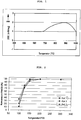
- FIG. 2 It can be seen that the inventive catalyst cat 1 allows complete conversion of isocyanic acid to ammonia and carbon dioxide even at 150 ° C and at temperatures of 100 ° C a better conversion than the comparative catalysts Cat 2 and 3 Kat achieved.
- Cat 2 (SiO 2 content of 15% by weight) and cat 3 (SiO 2 content of 1.5% by weight) have inferior values.
- Table 1 shows the compositions of the catalysts thus obtained cat 1 to cat 4 (data in each case in wt .-%, Kat 4 without SiO 2 ).
- Table 1 shows the compositions of the catalysts thus obtained cat 1 to cat 4 (data in each case in wt .-%, Kat 4 without SiO 2 ).
- the catalysts Cat 1 to Cat 4 were also applied to planar test sheets to perform adhesion tests. There Two different test procedures were used, which are explained below:
- the test apparatus used is in the FIGS. 3 and 4 and consists of a fixing unit for the test sheet, a pressure regulator and a nozzle, which is laterally directed to the center of the test sheet.
- the corresponding coated sheet width 2.5 cm
- the pre-pressure on the manometer is set to 6 bar.
- the test time is 15 sec.
- the sheet is vibrated by the flowing compressed air and simulates the conditions in the exhaust gas flow of a vehicle.
- the evaluation is done by weighing.
- the percentage removal of coating composition is determined by the weight determination before and after the test.
- the test apparatus used is in FIG. 5 and consists of a fixing unit for the test sheet in a test vessel and an ultrasonic generator.
- the test vessel 200 g of dist. H 2 O weighed.
- the module generator 54% of the maximum amplitude is set.
- the number of pulses has been set to 4.
- the duration of a pulse is 1.5 sec.
- the corresponding coated test sheet is filled with dist. Washed off H 2 O and then introduced into the holder at the bottom of the test vessel.
- the sheet is vibrated by the ultrasound and there is a corresponding removal of the coating.
- the evaluation is done by weighing.
- the percentage removal of coating composition is determined by the weight determination before and after the test in the dry state.
Landscapes
- Chemical & Material Sciences (AREA)
- Engineering & Computer Science (AREA)
- Chemical Kinetics & Catalysis (AREA)
- Materials Engineering (AREA)
- Organic Chemistry (AREA)
- Environmental & Geological Engineering (AREA)
- Health & Medical Sciences (AREA)
- Biomedical Technology (AREA)
- Analytical Chemistry (AREA)
- General Chemical & Material Sciences (AREA)
- Oil, Petroleum & Natural Gas (AREA)
- Combustion & Propulsion (AREA)
- Exhaust Gas Treatment By Means Of Catalyst (AREA)
- Catalysts (AREA)
Description
- Die vorliegende Erfindung betrifft einen Harnstoff-Hydrolyse-Katalysator umfassend eine katalytisch aktive Zusammensetzung enthaltend Titandioxid, Siliziumdioxid und eine Schwefelverbindung.
- Ausserdem wird ein Abgasreinigungssystem zur Entstickung von Abgasen mobiler und stationärer Verbrennungsanlagen unter Verwendung des Harnstoff-Hydrolyse-Katalysators beschrieben
- Fahrzeugkatalysatoren dienen der chemischen Umwandlung von Verbrennungsprodukten wie Kohlenwasserstoffen (HmCn), Kohlenstoffmonoxid (CO) und Stickoxide (NOx) in KFZ Abgasen. Insbesondere Stickoxidemissionen NOx können lokale Reizungen der Atemwege hervorrufen oder in Kontakt mit Wasser in der Atmosphäre durch Säurebildung zu "Saurem Regen" führen. Daher ist man bestrebt, Stickoxide möglichst vollständig mittels Katalysatoren aus dem Abgasstrom zu entfernen.
- Bei einem KFZ Ottomotor kann beispielsweise mit einem Drei-Wege-Katalysator die Oxidation von CO und HmCn, sowie die Reduktion von NOx parallel stattfinden.
- Bei einem Dieselmotor verhindert der Sauerstoffüberschuss im Abgas die Reduktion des NOx und macht spezielle Katalysatoren erforderlich. Daher kommen beim Dieselmotor sogenannte NOx-Speicherkatalysatoren oder SCR-Katalysatoren zum Einsatz.
- Am SCR Katalysator (selective catalytic reduction) ist die Reduktion der Stickoxide selektiv. Das heißt, es werden bevorzugt die Stickoxide (NO, NO2) reduziert, während Nebenreaktionen, wie die Oxidation von SO2 zu SO3, weitgehend unterdrückt werden.
- Dabei werden die Stickoxide durch Reduktion mit dem Reduktionsmittel Ammoniak, das dem Abgas zugemischt wird, in Wasser (H2O) und Stickstoff (N2) umgewandelt.
NO + NO2 + 2NH3 • 2N2 + 3H2O
- Da (gasförmiger) Ammoniak ein Sicherheitsrisiko darstellt und in Druckflaschen zu handhaben ist, wird der für die oben dargestellte benötigte Ammoniak in Form einer 32,5 %-igen, wässrigen Harnstofflösung bereitgestellt, die als AdBlue® bezeichnet wird.
- Diese wird kontinuierlich, z.B. mittels einer Dosierpumpe oder einem Injektor in den Abgasstrom eingespritzt, wobei durch Hydrolyse Wasser und Ammoniak entstehen. Das entstandene NH3 ist bei geeigneter Temperatur in der Lage, die Stickoxide im Abgas zu Stickstoff zu reduzieren. Typischerweise liegt der Verbrauch an Harnstoff-Wasser-Lösung in der Größenordnung von etwa 2 bis 8% des eingesetzten Dieselkraftstoffs.
- Das SCR-System kann hierzu vier Reaktionsstufen umfassen, mit jeweils einem verschiedenen Katalysatortyp beschleunigt werden: dem V-Kat, H-Kat, SCR-Kat und dem Oxi-Kat.
- In einem ersten Schritt wird mit dem sogenannten Vor-Katalysator (V-Kat) NO teilweise zu NO2 oxidiert. Dies dient dazu das NO zu NO2-Verhältnis in einem Bereich von 1:1 einzustellen, so dass die nachfolgende reduktive Entfernung der Stickoxide nach dem wesentlich schnelleren "Fast-SCR"-Mechanismus erfolgen kann. Durch diesen Mechanismus werden NO und NO2 mit NH3 katalytisch zu N2 und H2O umgesetzt.
- Die Umwandlung der eingespritzten Harnstofflösung unter vollständiger Verdampfung des Wassers zu gasförmigem Ammoniak erfolgt in zwei Schritten mit dem Harnstoffhydrolysekatalysator (H-Kat). Zuerst erfolgt die Thermolyse von Harnstoff, der sich thermisch in ein Äquivalent Ammoniak und ein Äquivalent Isocyansäure zersetzt. Aus der Isocyansäure wird dann durch eine Hydrolysereaktion ein weiteres Äquivalent Ammoniak und CO2 gebildet. Die Hydrolyse findet am Harnstoff-Hydrolyse-Katalysator (H-Kat) statt, der im Abgassystem vor dem SCR-Katalysator positioniert wird. Die Aufgabe des H-Kats besteht in der möglichst quantitativen Umwandlung von Harnstoff in Ammoniak.
- Thermolyse:
CH4N2O -> NH3 + HNCO
- Hydrolyse:
HNCO + H2O -> NH3 + CO2
- Anschließend erfolgt die Reduktion des Stickoxidgemisches mit dem entstandenen Ammoniak nach dem "Fast-SCR" Mechanismus und dem SCR-Kat.
2 NO + 2 NO2 + 4 NH3 -> 4 N2 + 6 H2O
"Fast-SCR" - Es kann vorkommen, dass zu viel Harnstoff zugeführt wird, so dass das daraus gebildete Ammoniak nicht mehr vollständig mit NOx reagieren kann. Bei dieser Fehldosierung kann Ammoniak, als sogenannter NH3-Schlupf, in die Umgebung gelangen. Abhilfe schafft man, indem hinter dem SCR-Katalysator ein Oxidationskatalysator (Oxi-Kat) angeordnet wird. Dieser Sperrkatalysator wandelt im Falle einer unerwünschten Ammoniak-Emission das NH3 wieder in N2 und H2O um.
- Das Funktionieren des gesamten SCR Systems hängt also wesentlich von der Effizienz der Ammoniakbereitstellung durch den H-Kat ab. Typische aktive Beschichtungen für den Hydrolyse-Katalysator (H-Kat) sind Metalloxide, insbesondere das schwach saure Titandioxid in der Anatas-Modifikation als Aktivkomponente. Diese aktiven Massen werden mit Hilfe eines Beschichtungsverfahrens auf einen metallischen oder keramischen Trägerkörper mit Wabenstruktur aufgebracht.
- Die Beschichtung der Trägerstrukturen des H-Kats erfolgt mit einem sogenannten "Washcoat", der üblicherweise Titandioxid und einen Binder enthält. Durch den Einsatz geeigneter Binder (häufig anorganische Sole) kann die mechanische Stabilität der Beschichtung auf der Oberfläche verbessert werden. Insbesondere bei der Verwendung von metallischen Substraten stellt aber die Aufbringung von gut haftenden und zugleich aktiven Beschichtungen eine große Herausforderung dar.
- Weiterhin wird vorzugsweise die Harnstofflösung als feiner Nebel von sehr kleinen Teilchen (kleiner 10 µm) auf den Katalysator geführt. Im Idealfall würde also bei der am H-Kat erfolgenden NH3-Freisetzung eine vollständige Verdampfung der Harnstofflösung stattfinden, bevor der Harnstoff auf den Hydrolyse-Katalysator trifft. In der Realität ist die Verdampfungsstrecke im Abgasstrang für eine vollständige Verdampfung zu kurz, so dass größere Tropfen auf die Eintrittsfläche des Katalysators treffen.
- Da die auf den Katalysator auftreffende Harnstofflösung durch Tropfenschlagerosion eine extreme Belastung für die Beschichtung darstellt, ist die mechanische Stabilität der Beschichtung für den H-Kat von wesentlicher Bedeutung.
- Weiterhin bestehen die derzeit üblicherweise verwendeten Harnstoff-Hydrolyse-Katalysatoren hautsächlich aus Titandioxid in der Anatas-Modifikation. Bei hohen Temperaturen kann es aber zu einer Phasenumwandlung von Anatas nach Rutil kommen. Die Rutil-Phase weist eine erheblich geringere Aktivität bezüglich der zu katalysierenden Hydrolysereaktion von Isocyansäure zu Ammoniak auf. Zudem sinkt die spezifische Oberfläche des Katalysators. Diese sogenannte Katalysatoralterung tritt insbesondere und beschleunigt ab einer Temperatur von 550 °C auf.
- Um die Katalysatoralterung zu verringern oder zeitlich zu verzögern, werden verschiedene Zusatzstoffe dem Titandioxid zugesetzt. Dabei handelt es sich insbesondere um Siliziumoxid, Oxide der Lanthanoide oder Wolframoxid. Diese Zusatzstoffe verlangsamen zwar das Altern des Katalysators, wirken sich jedoch negativ auf dessen Leistungsfähigkeit aus und verringern den Umsatz von Isocyansäure zu Ammoniak. Die Hydrolyseaktivität von stärker sauren Mischoxiden, die WO3 oder/und V2O5 enthalten, ist durch die starke Chemisorption des Thermohydrolyseprodukts Ammoniak generell geringer. Daher ist die Verwendung dieser Zusatzstoffe nachteilig.
- Aus dem
EP 0894523 B1 ist eine Verbrennungsanlage mit einem statischen Mischer zur Hydrolyse von Harnstoff für die selektive katalytische Reduktion von Stickoxiden bekannt. Die als H-Kat wirksame aktive Beschichtung des Mischers enthält Titandioxid mit Zusätzen wie Wolframtrioxid, Molybdäntrioxid und Vanadiumpentoxid. Durch den Zusatz von Sulfat und Phosphat wird eine höhere katalytische Aktivität erreicht. Es wird jedoch nicht das Problem der Temperaturstabilität und Haftfestigkeit der Beschichtung erkannt. Der Einsatz von Siliziumdioxid wird nicht erwähnt. Außerdem erfährt dieser H-Kat durch mischoxidische Zusätze die oben erwähnte Leistungsminderung. - Das
DE 19734627 C1 offenbart in Tabelle 3 einen beschichteten Verdampfer, dessen katalytische Beschichtung aus TiO2 und verschiedenen Mischoxiden besteht und eine erhöhte NOx Reduktionsaktivität aufweist. Allerdings wird hier nicht auf die Widerstandsfähigkeit gegen Tropfenschlagerosion oder die Haftfestigkeit der Beschichtung eingegangen. - Das
EP 0487886 B1 offenbart einen Hydrolyse-Katalysator der aus einer Mischung aus TiO2, Al2O3, SiO2 oder ZrO2 bestehen kann. Fünf- und sechswertige Elemente wie z.B. WO3 können zur Änderung der Säureeigenschaften, als Stabilisatoren und als Promotoren zugesetzt werden. - Das
EP 0555746 B1 offenbart einen Verdampfer, der als Strömungsmischer und Hydrolyse-Katalysator ausgebildet ist. Dabei wird durch den Einsatz nicht geradliniger Kanäle her ein höherer Wirkungsgrad der Harnstoffzersetzung erreicht. Die katalytische Beschichtung wird als H-Zeolith-haltige Abmischung von Al2O3 mit einem oder mehreren anderen Oxiden (TiO2, SiO2, ZrO2) beschrieben. - Das
EP 1153648 B1 offenbart einen Abgaskatalysator mit einer Vielzahl von Strömungspfaden, der sich durch eine zusätzliche Hydrolysebeschichtung auf einem SCR-Katalysator auszeichnet. Diese Hydrolysebeschichtung kann aus TiO2, Al2O3, SiO2 oder ZrO2 bestehen. - Die
WO2008/089956 A2 offenbart eine Vorrichtung zur selektiven katalytischen NOx-Reduktion in Abgasen unter Einsatz eines Harnstoff -Hydrolyse Katalysators der aus TiO2 in der Anatasmodifikation besteht und der mit einem Washcoat hergestellt wird, dem eine ausreichend grosse Menge von 15-bis 30 Gew% an z.B SiO2 Sol als Binder zur Erhoehung der Haftfestigkeit der Washcoat Suspension auf einem Traeger zugesetzt wurde. - Die
EP 0615777 A1 offenbart eine Vorrichtung zur selektiven katalytischen Reduktion von NOx in sauerstoffhaltigen Abgasen enthaltend einen Harnstoff-Hydrolyse- und einen SCR-Katalysator. Der Harnstoff-Hydrolyse-Katalysator enthaelt TiO2, Al2O3 und SiO2. In einem Ausführungsbeispiel wird ein Material mit 73 Gew.-% TiO2 und 6,7 Gew-% SiO2 offenbart. DieUS2003/0103889A1 offenbart ein Verfahren zur Herstellung von thermisch stabilen Silizium enthaltenden Titandioxid, bei dem Titanhydroxid or Titandioxid mit eine, Silica-Sol umgesetzt werden, wobei das entstehende TiO2 in der Anatasform durch SiO2 stabilisiert wird. In einem Ausführungsbeispiel wird ein Material mit 90 Gew.-% TiO2, < 10 Gew-% SiO2 und 0,24 Gew-% Schwefel offenbart. Die Katalysatoren des Standes der Technik weisen den Nachteil auf, dass sie gegen Tropfenschlagerosion unbeständig sind und auch eine ungenügende Haftfestigkeit der Beschichtung aufweisen, obwohl diese für die Leistungsfähigkeit eines Hydrogenkatalysators von Bedeutung sind. Weiterhin besteht die ungelöste Problematik der Temperaturstabilität der katalytisch aktiven Beschichtung. - Es bestand daher die Aufgabe, einen Harnstoff-Hydrolyse-Katalysator bereitzustellen, bei dem der Titandioxidanteil bei höheren Temperaturen keiner Phasenumwandlung von Anatas nach Rutil unterliegt und der eine gute Alterungsbeständigkeit aufweist und dadurch auch bei kurzfristig auftretenden erhöhten Temperaturspitzen nur wenig in seiner katalytischen Aktivität beeinflusst wird.
- Zudem sollte der Harnstoff-Hydrolyse-Katalysator gegen die mechanischen Belastungen beim Tropfenschlag während der Harnstoffhydrolyse beständiger sein, ohne Einbußen bei der katalytischen Aktivität hinnehmen zu müssen.
- Erfindungsgemäß wird die Aufgabe gelöst durch einen Harnstoff-Hydrolyse-Katalysator, umfassend eine auf einem Träger aufgebrachte katalytisch aktive Zusammensetzung enthaltend 92-96 Gew% Titandioxid in der Anatas-Modifikation, 3,0 -7,0 Gew.% Siliziumdioxid und eine Schwefelverbindung in einer Menge bezogen auf die gesamte katalytisch aktive Zusammensetzung von 0,3 bis 0,4 Gew% (berechnet als elementarer Schwefel), und hergestellt mit einer Washcoat-Suspension enthaltend ein Titandioxid in der Anatas-Modifikation, ein Polysiloxan und eine Schwefelverbindung.
- Die katalytisch aktive Zusammensetzung des erfindungsgemäßen Harnstoff-Hydrolyse-Katalysators erweist sich auf dem Träger als besonders haftfest und ist besonders widerstandsfähig gegenüber Tropfenschlagerosion und ist dabei trotzdem außerordentlich aktiv bei der Harnstoff-Hydrolyse.
- Der Anteil an SiO2 in der katalytisch aktiven Zusammensetzung bzw. im fertigen Katalysator stammt bevorzugt aus organischen Siliziumverbindungen im weiter unten beschriebenen Washcoat (beispielsweise Siloxane oder Silane, z.B. aus der Silres-oder Geniosil-Reihe der Fa. Wacker) und nicht wie üblicherweise im Stand der Technik aus mit SiO2 thermisch vorstabilisiertem TiO2. Der organische Anteil der Siliziumverbindungen wird bei der Kalzinierung thermisch zersetzt und es verbleibt SiO2 im Katalysator. Anatas wird dadurch vorteilhafterweise in-situ stabilisiert.
- Es ist jedoch ebenso möglich beispielsweise ein SiO2-Sol oder auch festes SiO2 einzusetzen.
- Weiter enthält die katalytisch aktive Zusammensetzung eine Schwefelverbindung. Bezogen auf die gesamte katalytisch aktive Zusammensetzung (und berechnet als elementarer Schwefel) ist Schwefel in einem Anteil von 0,3 bis 0,4 Gew.-% enthalten. Der Schwefel liegt dabei typischerweise als Sulfat vor. Das Sulfat kann dabei auch erst während der Herstellung des Katalysators bzw. der katalytisch aktiven Zusammensetzung aus entsprechenden Ausgangsverbindungen entstehen oder schon in der weiter unter beschriebenen Washcoat-Suspension als Sulfat vorliegen.
- Als überaus geeignet hat sich eine katalytisch aktive Zusammensetzung aus 94,4 Gew.-% TiO2, 5,3 Gew.-% SiO2 und 0,3 Gew.-% Schwefel erwiesen.
- Für spezielle Anwendungen kann die Haftung der erfindungsgemäßen Zusammensetzung am Träger durch eine zusätzliche sogenannte "Primerschicht" verbessert werden. Die erfindungsgemäße "Primerschicht" weist verglichen mit der eigentlichen katalytischen Zusammensetzung einen höheren Binderanteil bezogen auf den Anteil an TiO2 auf. D.h. die Mengen an TiO2 und/oder TiO2-Sol im Washcoat werden verringert und die Menge an Siliziumverbindungen im Washcoat erhöht. Je weniger TiO2 in der "Primerschicht" vorhanden war, desto besser erwies sich die Haftung der Primerschicht am Träger. Die Primerschicht ist dabei bevorzugt frei von schwefelhaltigen Verbindungen jedoch kann sie in bestimmten Weiterbildungen der vorliegenden Erfindung auch eine Schwefelverbindung umfassen. Eine ganz besonders bevorzugte Zusammensetzung einer Primer-Washcoat-Suspension besteht aus 10 kg TiO2 in Mischung mit 40 kg Silres MP 42 E.
- Erfindungsgemäß wird die katalytisch aktive Zusammensetzung bzw. deren Vorläufer auf einen Träger aufgebracht, wobei der Träger aus einer Keramik, einem Metall oder einer Metalllegierung besteht.
- Vorzugsweise liegt der Träger in Form eines Wabenkörpers, eines Monolithen, eines Rohrs oder eines Schaums vor.
- Mit metallischen Substraten lassen sich dabei Beladungen mit der erfindungsgemäßen katalytisch aktiven Zusammensetzung von bis zu 200 g/l darstellen, die trotz der hohen Beladung eine extrem gute Haftung aufweisen. Die optimale Beladung für den erfindungsgemäßen Zweck liegt bei 80 g/l ± 10 %.
- Besonders bevorzugt ist die erfindungsgemäße katalytisch aktive Zusammensetzung auf typischen Trägern für Ausgangskatalysatoren aus FeCrAl-Legierungen, die hitze- und korrosionsbeständig aufgebracht. Derartige Träger sind z.B. in der
EP 0 487 886 B1 offenbart. - In gleicher Weise können Katalysatorträger aus keramischem Material Verwendung finden. Häufig wird es sich bei dem keramischen Material um ein inertes niedrigoberflächiges Material wie Cordierit, Mullit, alpha-Aluminiumoxid oder Siliziumcarbid handeln. Jedoch kann der verwendete Katalysatorträger auch aus hochoberflächigem Trägermaterial wie gamma-Aluminiumoxid bestehen.
- Anstelle auf die vorstehend genannten Träger kann der Hydrolyse-Katalysator bzw. die katalytisch aktive Zusammensetzung in bzw. auf einem der üblichen Bauteile eines Abgasreinigungssystems aufgebracht werden, beispielsweise auf eine Verdampfereinheit, auf bzw. in einer Dosierleitung, auf bzw. in einer Zufuhrleitung mit der der Harnstoff-Hydrolyse-Katalysator mit der Abgasleitung verbindbar ist oder zumindest auf Teilen einer Zufuhrleitung zur Zufuhr des gasförmigen Stoffgemisches zum eigentlichen Harnstoff-Hydrolyse-Katalysator oder auf Teilen der Verbindungseinheit.
- Dies erhöht die Umsetzungseffektivität und erlaubt es, den Harnstoff-Hydrolyse-Katalysator entsprechend kleinvolumiger mit einer kleineren katalytisch aktiven Oberfläche auszubilden.
- Weiter wird vorliegend die Verwendung einer geträgerten katalytisch aktiven Zusammensetzung, wie oben definiert, enthaltend Titandioxid, Siliziumoxid und eine Schwefelverbindung als Harnstoff-Hydrolyse-Katalysator beschrieben. Insbesondere liegt die geträgerte katalytisch aktive Zusammensetzung als Beschichtung auf einem Katalysatorträgerkörper vor und zeigt verbesserte Haftungseigenschaften auf dem Katalysatorträgerkörper. Hinsichtlich der weiteren bevorzugten Ausgestaltungen der katalytisch aktiven Zusammensetzung gelten die oben beim Harnstoff-Hydrolyse-Katalysator genannten Bevorzugungen.
- Ausserdem wird eine Washcoat-Suspension zur Herstellung der katalytisch aktiven Zusammensetzung des erfindungsgemäßen Hydrolysekatalysators beschrieben.
- Die Washcoat-Suspension enthaelt Titandioxid, ein Polysiloxan als Bindemittel, und eine Schwefelverbindung. Dabei liegt das Titandioxid bevorzugt in der Anatas-Modifikation vor.
- Unter dem Begriff "siliziumorganische Verbindung" werden Verbindungen verstanden, die sich von Silan (SiH4) durch Austausch eines oder mehrerer H-Atome durch organische Reste R ableiten, wobei die Reste R mit den Siliziumatomen über Einfach- oder Mehrfachbindungen mit den ein- bis sechszähligen ungeladenen oder geladenen Si-Atomen verknüpft sein können. Weiter fallen unter diesen Begriff sogenannte Silikonkautschuke, Organyloligo- und -polysilane, Organylsilylene, Silene und Siline, Siloxane bzw. Polysiloxane.
- Washcoat-Suspensionen enthalten in der Regel eine Dispersion aus Wasser als Lösungsmittel und äußerst feinkörnige Metalloxide, z.B. Titandioxid oder Aluminiumoxide, mit denen der Katalysatorträger beschichtet wird. Hierbei kann es sich insbesondere um Sol-Gel Systeme handeln.
- Überraschenderweise hat sich gezeigt, dass die Verwendung der Polysiloxanverbindung in Kombination mit der Schwefelverbindung zu einer Stabilisierung der Anatas-Modifikation des TiO2 führt, ohne dass sich dies negativ auf die Aktivität des späteren Katalysators auswirkt. Die Phasenumwandlung in das weniger aktive Rutil tritt erst ab einer Temperatur von 690 °C auf und ist damit um ca. 100 °C zu höheren Temperaturen verschoben als bei nicht stabilisiertem Anatas zu erwarten wäre. Die verschobene Phasenumwandlung von Anatas zu Rutil lässt sich gut in der entsprechenden DSC-Kurve erkennen (vgl.
Figur 1 ). Damit wird einem Leistungsabfall des Katalysators bei eintretenden Temperaturspitzen entgegengewirkt. - Ein weiterer Vorteil bei der Verwendung der Washcoat-Zusammensetzung liegt darin, dass sich wie vorstehend schon erwähnt damit auf metallischen Substraten Beladungen von bis zu 200 g/l darstellen lassen. Die nach der Kalzinierung des Washcoats resultierenden Beschichtungen aus den erfindungsgemäßen katalytisch aktiven Zusammensestzungen weisen trotz der hohen Beladung eine extrem gute Haftung auf.
- In einer bevorzugten Ausgestaltung umfasst die Washcoat-Suspension ferner ein Titandioxid-Sol. Insbesondere die Kombination der beiden Binderkomponenten Titandioxid-Sol und siliziumorganische Verbindung führt zu einer guten Vernetzung.
- In einer besonders bevorzugten Ausführungsform umfasst die Washcoat-Suspension als Polysiloxaneines in Form einer Silikonharzemulsion, bevorzugt Silres MP42 E®, als Bindemittel.
- Die Washcoat-Suspension weist einen Schwefelanteil von 0,01 bis 10 Gew.-% auf. Besonders bevorzugt ist ein Anteil von 0,01 bis 1,0 Gew.-%, mehr bevorzugt ein Anteil von 0,1 bis 0,6 Gew. %, insbesondere bevorzugt 0,3 bis 0,4 Gew.-% Schwefel. Die Angaben beziehen sich auf den Gesamtschwefelgehalt der in der Washcoat Suspension vorliegenden Schwefelverbindung. Geeignete Schwefelverbindungen sind z.B. Sulfate, Sulfite, Thiosulfate, Peroxodisulfate, Schwefelsäure usw. insbesondere deren Titansalze. Ganz besonders bevorzugt ist Titandisulfat und Titanylsulfat.
- Überraschenderweise wirkt sich der Schwefelgehalt auf die Eigenschaften der erfinderischen Washcoat-Suspension aus. Mit höherem oder auch niedrigerem Gehalt an Schwefel bzw. Schwefelverbindung steigt auch die Viskosität des Washcoats.
- Die erhöhte Viskosität bewirkt eine wesentlich schlechtere Verarbeitbarkeit bei der Trägerbeschichtung (Befüllung und Entleerung) und schlechtere Haftungseigenschaften der Beschichtung auf der Substratoberfläche.
- Die Washcoat-Suspension weist vorzugsweise einen Feststoffgehalt von 40,0 bis 60,0 Gew.-%, bevorzugt von 46,0 bis 52,0 Gew.-% auf.
- Es wurde festgestellt, dass sich die Washcoat-Suspensionen trotz ihres verhältnismäßig hohen Feststoffanteils mittels des erfindungsgemäßen Verfahrens besonders einfach und gleichmäßig auf einen Katalysatorträger aufbringen lassen.
- Weitere anorganische Komponenten der Washcoatdispersion stellen beispielsweise feinteilige und hochoberflächiqe Oxide wie Aluminiumoxid, Siliziumdioxid, Seltenerdoxide, Nickeloxid, Eisenoxid, Erdalkalimetalloxid, Silizide wie Molybdansilizid, und/oder Zeolithe. Diese Stoffe können ganz oder teilweise als Oxide und/oder als beliebige lösliche und/oder unlösliche Verbindungen, zum Beispiel als Nitrate, Acetate, Oxalate, Tartrate, Formiate, Carbonate oder Hydroxide in der Suspension vorliegen. In letzterem Fall erfolgt dann üblicherweise die Überführung in die katalytisch aktive Spezies, bzw. in das feinteilige Beschichtungsmaterial meist durch thermische Zersetzung. Bevorzugt finden Katalysatorformulierungen Verwendung mit gegebenenfalls stabilisiertem Aluminiumoxid und Ceroxid, Zirkonoxid, Seltenerdoxiden, Erdalkalimetalloxiden, Platinmetallen und/oder deren Vorläufer bzw. deren Mischungen. Vorzugsweise enthält die Washcoat-Suspension auch übliche Dispergiermittel, um die Washcoat-Suspension zu stabilisieren.
- Bei der Herstellung der Washcoat-Suspension ist es wichtig, die Mischungsreihenfolge zu beachten. Wird ein TiO2-Sol verwendet, so muss dieses zuerst vorgelegt werden. Dann kann ggf. zusätzliches TiO2 sowie die Schwefelverbindung portionsweise zugegeben und eingerührt werden. Erst zum Schluss wird die siliziumorganische Verbindung beigemischt und eingerührt. Damit wird eine optimale Vernetzung der Binderkomponenten TiO2-Sol und siliziumorganische Verbindung gewährleistet und eine entsprechend gute Haftfestigkeit der Beschichtung auf einem Substrat bzw. Träger erzielt.
- Bevor der Washcoat zum Beschichten verwendet werden kann, wird er bevorzugt mindestens 2 Tage bei Raumtemperatur belassen und so gealtert.
- Die Washcoat-Suspension wird für die Herstellung des Harnstoff-Hydrolyse-Katalysators verwendet und ergibt nach Kalzinieren die katalytisch aktive Zusammensetzung.
- Die Aufbringung der katalytisch aktiven Zusammensetzung des Harnstoff-Hydrolyse-Katalysators bzw. der Washcoat-Suspension erfolgt dabei üblicherweise nach im Stand der Technik bekannten Methoden, wie z.B. durch Beschichtung im Tauchbad oder durch Sprühbeschichtung. Geeignete Verfahren sind beispielhaft in der
WO 2008/019857 A1 , derEP 1885495 A2 , derWO 2006/125648 A2 , derWO 2007/057209 A1 oder derWO 2007/057210 A1 beschrieben worden. - Bevorzugt wird der Washcoat durch Tauchen in eine Washcoat-Suspension in die Kanäle der Substrate gebracht. Es ist aber auch möglich die Washcoatbeschichtung durch mehrfaches Aufsprühen, insbesondere der Eintrittsstirnfläche des Trägerkörpers aufzubringen. Hiernach werden die Kanäle bevorzugt durch Ausblasen wieder durchlässig gemacht. Der Träger kann bevorzugt in einem Luftstrom bei 120 °C getrocknet werden.
- Das erfindungsgemäße Verfahren zur Herstellung eines Harnstoff-Hydrolyse-Katalysators umfasst daher bevorzugt die folgenden Schritte des:
- a)Aufbringens der Washcoat-Suspension enthaltend ein Titandioxid in der Anatas-Modifikation, ein Polysiloxan und eine Schwefelverbindung auf einen Träger,
- b)Entfernens der überschüssigen Washcoat-Suspension vom Träger
- c)Trocknens des feuchten Trägers
- d)Kalzinierens des beschichteten Trägers
- e)Abkühlen des beschichteten Trägers
- Vorzugsweise erfolgt Schritt a) durch Tauchen des Trägers in die Washcoat-Suspension.
- Besonders bevorzugt ist weiter das Einbringen des Washcoats durch Aussetzen des Tauchbades einer Vibration.
- Im Schritt b) werden die Kanäle des Trägers bevorzugt mit Druckluft ausgeblasen oder überschüssiges Beschichtungsmaterial abgesaugt.
- Noch bevorzugter ist im Schritt b) die anschließende Entleerung des überschüssigen Washcoats durch eine Zentrifuge. Diese Methode hat sich insbesondere bei strukturierten Substraten mit Schaufeln und Perforationen bewährt.
- Als sehr wichtig für die Leistungsfähigkeit des erfindungsgemäßen Katalysators bzw. der katalytisch aktiven Zusammensetzungen hat sich die thermische Behandlung des mit dem Washcoat beschichteten Trägers herausgestellt. Es hat sich gezeigt, dass der Trocknungsschritt nicht zu kurz sein darf.
- Bei einer sofortigen Kalzinierung bei hohen Temperaturen kann es zu einer Art "Verglasung" auf der Oberfläche kommen, die die Poren dicht macht und damit keine ausreichend hohe Oberfläche für die Reaktion mehr vorhanden ist. Bevorzugt ist, wenn die enthaltene Feuchtigkeit langsam bei 80 °C entfernt wird.
- Vorzugsweise wird daher der noch feuchte mit Washcoat Suspension beschichtete Träger in Schritt c) für mindestens zwei Stunden, bevorzugt 3 bis 10 Stunden, bei vorzugsweise 50 bis 150 °C, besonders bevorzugt 80 °C, bis zur Massenkonstanz getrocknet. Bei sehr großen Substraten muss die Trockenzeit entsprechend angepasst werden. Vorzugsweise wird im Umlufttrockenschrank gearbeitet.
- Anschließend wird der beschichtete Träger in Schritt d) für 1 bis 20 Stunden, bevorzugt 8 bis 12, besonders bevorzugt 9 bis 11 Stunden, bei 100 bis 1000 °C, bevorzugt 300 bis 600 °C, besonders bevorzugt 400 bis 500 °C kalziniert. Hierbei wird typischerweise ein Umluftofen verwendet.
- Die Abkühlung in Schritt e) nach der Kalzinierung sollte möglichst kleiner 20 K/min, bevorzugt 10 K/min, besonders bevorzugt kleiner 5 K/min, insbesondere 1 bis 4 K/min betragen.
- Die Beschichtung des Trägers erfolgt mit einer Konzentration von 40 bis 200 g/l, bevorzugt von 60 bis 160 g/l pro Volumen des Trägers.
- In einer besonderen Ausgestaltung des erfindungsgemäßen Verfahrens kann wie schon vorstehend kurz erläutert auf den Träger zunächst eine als Haftvermittler (Primerschicht) für die erfindungsgemäße Zusammensetzung dienende Precoatlösung oder -dispersion aufgebracht werden. Wie vorstehend schon gesagt, verbessert ein hoher Gehalt an Polysiloxan die Haftung. Ein typischer Ansatz ist beispielsweise: 10 kg TiO2 vermischt mit 40 kg Silres MP 42 E. Die Suspension wird äußerst dünn aufgetragen, da die Aktivität bzgl. Hydrolyse relativ gering ist. Typische Beladungen auf Substraten liegen hier zwischen 2 und 15 g/l, bevorzugt bei ca. 8 - 10 g/l.
- Nachdem das Lösungsmittel entfernt wurde, beispielsweise durch Abdampfen, kann mittels des erfindungsgemäßen Verfahrens eine Washcoat-Suspension auf den Katalysatorträger aufgebracht werden.
- Gegenstand der Erfindung ist auch ein Harnstoff-Hydrolyse-Katalysator, welcher nach dem erfindungsgemäßen Verfahren hergestellt wurde.
- Verwendung findet der erfindungsgemäße Harnstoff-Hydrolyse-Katalysator in Systemen zur Bereitstellung von Ammoniak aus einer Harnstoff-Wasser Lösung.
- Der erfindungsgemäße Harnstoff-Hydrolyse-Katalysator eignet sich demgemäß hervorragend zum Einsatz in Abgasreinigungssystemen oder zur Verringerung von Stickoxidemissionen von mobilen und stationären Verbrennungseinrichtungen.
- Mobile Verbrennungseinrichtungen im Sinne der vorliegenden Erfindung sind beispielsweise Verbrennungsmotoren von Kraftfahrzeugen, insbesondere Dieselmotoren, Stromerzeugungsaggregate auf Basis von Verbrennungsmotoren oder sonstige Aggregate auf Basis von Verbrennungsmotoren.
- Bei den stationären Verbrennungseinrichtungen handelt es sich für gewöhnlich um Kraftwerksanlagen, Feuerungsanlagen, Müllverbrennungsanlagen und auch um Heizungssysteme von Privathaushalten.
- Die Erfindung ist anhand von Ausführungbeispielen sowie der Figuren näher erläutert, ohne dass diese als einschränkend verstanden werden sollen.
- Figur 1
- zeigt einen Ausschnitt aus einer DSC Kurve einer Washcoat-Suspension.
- Figur 2
- zeigt den Isocyansäureumsatz verschiedener Katalysatoren.
- Figur 3
- zeigt eine Testapparatur zur Haftfähigkeitsbestimmung mittels Pressluft.
- Figur 4
- zeigt eine vergrößerte Ansicht der Testapparatur zur Haftfähigkeitsbestimmung mittels Pressluft.
- Figur 5
- zeigt eine Testapparatur zur Haftfähigkeitsbestimmung mittels Ultraschall.
- Zur Herstellung eines erfindungsgemäßen Harnstoff-Hydrolyse-Katalysators wurde zuerst die Washcoat-Suspension bereitgestellt. Hierbei wurden die Ausgangsverbindungen in den folgenden Mengen eingesetzt:
- 20,0 kg TiO2 (in der Anatas-Modifikation mit einer Ti(O)SO4 Beimischung) Ti(O)SO4 ist dabei in dieser Mischung in einer Menge enthalten, die einem Gesamt-Schwefel-Gehalt von 0,35 Gew.-% bezogen auf die Gesamtmenge TiO2 entspricht
- 26,0 kg TiO2-Sol (Feststoffgehalt 12 %, pH = 1,1)
- 6,0 kg Silres MP 42 E® von Wacker (Polysiloxan + Wasser + Xylol)
- Zunächst wurde das TiO2-Sol in einem geeignetem Behälter (meist ein 50 bis 100 L Kunststofffass) eingewogen und bei niedriger Umdrehungszahl mit einem drei-blättrigen Propellerrührer gerührt.
- Danach wurde das TiO2-Pulver abgewogen und portionsweise dem TiO2-Sol zugegeben und eingerührt.
- Sobald das TiO2-Pulver homogen in der Flüssigkeit eingerührt war, wurde das Silres MP 42 E® abgewogen, der gerührten Suspension zugegeben und die Suspension weitere 15 Minuten gerührt. Anschließend wurde die so erhaltene Washcoatsuspension zweimal mit einer Zahnkolloidmühle MZ80® (Firma FrymaKoruma) vermahlen, bzw. dispergiert.
- Der Washcoat wies einen Feststoffgehalt von 49,0 Gew.-% ± 3,0 Gew.-% auf.
- Der Washcoat wurde vor dem Aufbringen auf einem Träger 5 Tage bei Raumtemperatur gealtert.
- Für die Beschichtung wurde ein Trägersubstrat (Wabenkörper (Monolith) erhältlich von der Firma EMITEC mit einer Zelligkeit von 400 cpsi) aus FeCrAl-Legierung durch vollständiges Eintauchen in die Washcoat-Suspension benetzt. Anschließend wurden die Kanäle des Trägers frei geblasen. Danach wurde der feuchte Monolith für mindestens 2 Stunden im Umlufttrockenschrank bei 80 °C bis zur Massenkonstanz getrocknet. Anschliessend wurde der Katalysator für 10 Stunden bei 450 °C im Umluftofen kalziniert. Die Aufheizrate betrug hierbei 10 K/min. Die darauf folgende Abkühlung erfolgte bei 2 K/min. Der so erhaltene Harnstoff-Hydrolyse-Katalysator kann z.B. in Abgasnutzungssystemen von Kraftfahrzeugen eingesetzt werden. Die katalytisch aktive Zusammensetzung wies folgende Anteile der Bestandteile (in Gew.-%) auf:
- 94,4 % TiO2, 5,3 % SiO2, 0,3% Schwefel (berechnet als elementarer Schwefel).
- Die Beladung betrug 100 g/L aktive Masse
Diese Zusammensetzung erwies sich als besonders haftfest und widerstandsfähig gegenüber Tropfenschlagerosion. - Gemäß Ausführungsbeispiel 1, wurden 3 weitere Trägersubstrate der Firma EMITEC aus FeCrAl-Legierung mit Washcoatsuspensionen beschichtet, um den Einfluss der Menge an SiO2 in der katalytisch aktiven Zusammensetzung in den Katalysatoren Kat 1 (erfindungsgemaess), Kat 2 und Kat 3 (Vergleich) zu bestimmen.
- Dabei wurde die Menge an Silres MP 42 E entsprechend erhöht bzw. erniedrigt um auf die entsprechenden SiO2-Gehalte im kalzinierten Katalysator zu kommen. Bei Katalysator 4 wurde auf die Zugabe von Silres MP 42 E verzichtet.
- Es wurden an den Katalysatoren Kat 1 bis Kat3
- Laborprüfstandsmessungen bei einer Raumgeschwindigkeit (GHSV) von 53.000 h-1 und einer Isocyansäuredosierung von 1000 ppm im N2-Strom (5 % H2O) durchgeführt, um den Umsatz an Isocyansäure zu verfolgen.
- Insbesondere wurde der Isocyansäureumsatz ab 100 °C bestimmt.
- Aus
Figur 2 ist ersichtlich, dass der erfindungsgemaesse Katalysator Kat 1 schon bei 150 °C einen vollständigen Umsatz von Isocyansäure zu Ammoniak und Kohlendioxid ermöglicht und bei Temperaturen von 100 °C einen besseren Umsatz als die Vergleichskatalysatoren Kat 2 und Kat 3 erreicht. - Kat 2 (SiO2-Gehalt von 15 Gew.-%) und Kat 3 (SiO2-Gehalt von 1,5 Gew.-%) weisen dem gegenüber schlechtere Werte auf.
- Tabelle 1 zeigt die Zusammensetzungen der so erhaltenen Katalysatoren Kat 1 bis Kat 4 (Angaben jeweils in Gew.-%, Kat 4 ohne SiO2).
TABELLE 1: Katalytisch aktive Zusammensetzungen der Katalysatoren Kat 1 bis Kat 4 TiO2 SiO2 S Kat 1 (erfindungsgemaess) 94,4 % 5,3 % 0,3 % Kat 2 84,7 % 15 % 0,3 % Kat 3 98,2 % 1,5 % 0,3 % Kat 4 99,7 % --- 0,3 % - Die Katalysatoren Kat 1 bis Kat 4 wurden zudem auf planare Testbleche aufgetragen um Haftungstests durchzuführen. Dabei wurden zwei unterschiedliche Testverfahren angewendet, die im Folgenden erläutert werden:
- Die verwendete Testapparatur ist in den
Figuren 3 und 4 zu sehen und besteht aus einer Fixiereinheit für das Testblech, einer Druckregulierung und einer Düse, welche seitlich auf die Mitte des Testblechs gerichtet ist. Für den Test wird das entsprechende beschichtete Blech (Breite 2,5 cm) in die Halterung eingespannt. Der Vordruck am Manometer wird auf 6 bar eingestellt. Die Testzeit beträgt 15 sec. Das Blech wird durch die strömende Druckluft in Schwingung versetzt und simuliert die Bedingungen im Abgasstrom eines Fahrzeugs. - Die Auswertung erfolgt über Auswiegen.
- Bei der Haftungsbeurteilung mittels Auswiegen wird der prozentuale Abtrag an Beschichtungsmasse durch die Gewichtsbestimmung vor und nach dem Test ermittelt.
- Die verwendete Testapparatur ist in
Figur 5 zu sehen und besteht aus einer Fixiereinheit für das Testblech in einem Testgefäß und einem Ultraschallerzeuger. In dem Testgefäß werden 200 g dest. H2O eingewogen. Am Modulgenerator werden 54 % der maximalen Amplitude eingestellt. Die Impulszahl wurde auf 4 festgelegt. Die Dauer eines Impulses beträgt 1,5 sec. Das entsprechende beschichtete Testblech wird mit dest. H2O abgewaschen und dann in die Halterung am Boden des Testgefäßes eingebracht. - Das Blech wird durch den Ultraschall in Schwingung versetzt und es kommt zu einem entsprechenden Abtrag der Beschichtung.
- Die Auswertung erfolgt über Auswiegen.
- Bei der Haftungsbeurteilung mittels Auswiegen wird der prozentuale Abtrag an Beschichtungsmasse durch die Gewichtsbestimmung vor und nach dem Test in trockenem Zustand ermittelt.
- Die Haftungsuntersuchungen ergaben folgende Ergebnisse:
Tabelle 2: Beschichtungsabtrag mittels Pressluft- und Ultraschalltest der Katalysatoren 1 bis 4. Beschichtungsabtrag in % Presslufttest Ultraschalltest Kat 1 (erfindungsgemaess) 3,0 4,3 Kat 2 1,5 2,1 Kat 3 12,2 17,4 Kat 4 32,1 48,7 - Die Ergebnisse zeigen deutlich die Abhängigkeit der Haftung vom Si-organischen Anteil im Washcoat. Eine Erhöhung des Anteils an Silres MP 42 E führt zu einer erheblichen Steigerung der Haftfestigkeit der Washcoatbeschichtung.
Claims (6)
- Harnstoff-Hydrolyse-Katalysator umfassend eine auf einem Träger aufgebrachte katalytisch aktive Zusammensetzung enthaltend 92-96 Gew% Titandioxid in der Anatas-Modifikation, 3,0 -7,0 Gew.% Siliziumdioxid und eine Schwefelverbindung in einer Menge bezogen auf die gesamte katalytisch aktive Zusammensetzung von 0,3 bis 0,4 Gew% (berechnet als elementarer Schwefel), und hergestellt mit einer Washcoat-Suspension enthaltend ein Titandioxid in der Anatas-Modifikation, ein Polysiloxan und eine Schwefelverbindung.
- Harnstoff-Hydrolyse-Katalysator nach Anspruch 1, wobei der Träger für die katalytisch aktive Zusammensetzung aus einer Keramik, einem Metall oder einer Metalllegierung besteht.
- Harnstoff-Hydrolyse-Katalysator nach Anspruch 2, wobei der Träger in Form eines Wabenkörpers, eines Monolithen, eines Rohrs oder eines Schaums vorliegt.
- Verfahren zur Herstellung eines Harnstoff-Hydrolyse-Katalysators gemäß einem der Ansprüche 1 bis 3, umfassend die Schritte des:a) Aufbringens einer Washcoat-Suspension enthaltend ein Titandioxid in der Anatas-Modifikation, ein Polysiloxan und eine Schwefelverbindung auf einen Träger,b) Entfernens der überschüssigen Washcoat-Suspension vom oder aus dessen Träger,c) Trocknens des feuchten Trägers,d) Kalzinierens des beschichteten Trägers,e) Abkühlens des beschichteten Trägers.
- Verfahren nach Anspruch 4, wobei Schritt c) für mindestens 2 Stunden bei 50 bis 150°C bis zur Massenkonstanz durchgeführt wird.
- Verfahren nach Anspruch 5, wobei die Abkühlung im Schritt e) bei kleiner 20 K/min erfolgt.
Applications Claiming Priority (1)
| Application Number | Priority Date | Filing Date | Title |
|---|---|---|---|
| DE102008046994.7A DE102008046994B4 (de) | 2008-09-12 | 2008-09-12 | Harnstoff-Hydrolyse-Katalysator |
Publications (2)
| Publication Number | Publication Date |
|---|---|
| EP2172266A1 EP2172266A1 (de) | 2010-04-07 |
| EP2172266B1 true EP2172266B1 (de) | 2017-11-15 |
Family
ID=41571136
Family Applications (1)
| Application Number | Title | Priority Date | Filing Date |
|---|---|---|---|
| EP09011568.4A Not-in-force EP2172266B1 (de) | 2008-09-12 | 2009-09-09 | Harnstoff-Hydrolyse-Katalysator |
Country Status (3)
| Country | Link |
|---|---|
| EP (1) | EP2172266B1 (de) |
| CN (1) | CN101708473B (de) |
| DE (1) | DE102008046994B4 (de) |
Families Citing this family (12)
| Publication number | Priority date | Publication date | Assignee | Title |
|---|---|---|---|---|
| US20110064633A1 (en) * | 2009-09-14 | 2011-03-17 | Ford Global Technologies, Llc | Multi-Functional Catalyst Block and Method of Using the Same |
| CN102658159B (zh) * | 2012-04-23 | 2013-09-25 | 吉林大学 | 一种用于固态尿素水解制氨的催化剂涂层及其制备方法 |
| CN103588279A (zh) * | 2013-10-15 | 2014-02-19 | 常州思宇环保材料科技有限公司 | 一种高浓度氨氮废水的处理装置 |
| JP2016043320A (ja) * | 2014-08-25 | 2016-04-04 | エヌ・イーケムキャット株式会社 | 尿素加水分解触媒及び尿素加水分解材料を用いた選択還元触媒 |
| DE102015108014B3 (de) | 2015-05-20 | 2016-11-24 | Chemisch Thermische Prozesstechnik Gmbh | Verfahren und Anlage zur Reinigung von mit Stickoxiden beladenen Abgasen |
| DE102015014312A1 (de) * | 2015-11-05 | 2017-05-11 | Tropinon Enterprises Ltd. | Verfahren zur Minderung der NOx-Emission im Abgasstrang eines Fahrzeugs mit Verbrennungsmotor |
| CN107715879B (zh) * | 2017-10-11 | 2021-03-16 | 四川美丰化工股份有限公司 | 一种异氰酸分解用催化剂制备方法及所制催化剂使用方法 |
| US11300025B2 (en) | 2018-11-06 | 2022-04-12 | Cummins Emission Solutions Inc. | Systems and methods for reducing reductant deposit formation in a decomposition reactor of an exhaust gas aftertreatment system for an internal combustion engine |
| CN113070054B (zh) * | 2021-03-02 | 2023-07-14 | 中国华电科工集团有限公司 | 一种非负载型催化剂的制备方法及产品和应用 |
| CN113441131A (zh) * | 2021-07-12 | 2021-09-28 | 山东江宇环保科技有限公司 | 一种co-ch-scr协同脱硝催化剂及其制备方法 |
| JP7044442B1 (ja) * | 2021-08-18 | 2022-03-30 | 株式会社三井E&Sマシナリー | 触媒塗膜形成材料が形成されたステンレス金属シート、ステンレス金属配管及び尿素scr排ガス処理装置 |
| CN114768886B (zh) * | 2022-03-17 | 2023-09-29 | 西安热工研究院有限公司 | 一种复合金属氧化物催化剂的涂覆方法 |
Citations (3)
| Publication number | Priority date | Publication date | Assignee | Title |
|---|---|---|---|---|
| EP0345695A2 (de) * | 1988-06-09 | 1989-12-13 | W.R. Grace & Co.-Conn. | Katalysatoren zur selektiven katalytischen Reduktion in der Denitrierungstechnologie |
| US5330953A (en) * | 1992-06-20 | 1994-07-19 | Tioxide Specialties Limited | Preparation of anatase titanium dioxide |
| EP1524024A1 (de) * | 2003-10-15 | 2005-04-20 | Haldor Topsoe A/S | Katalysator-Träger, daraus hergestellter Katalysator und Prozess für die Reinigung von Abgasen |
Family Cites Families (23)
| Publication number | Priority date | Publication date | Assignee | Title |
|---|---|---|---|---|
| JPS6090043A (ja) * | 1983-10-21 | 1985-05-21 | Nippon Shokubai Kagaku Kogyo Co Ltd | 窒素酸化物浄化用触媒 |
| DE4038054A1 (de) | 1990-11-29 | 1992-06-04 | Man Technologie Gmbh | Verfahren und vorrichtung zur selektiven katalytischen no(pfeil abwaerts)x(pfeil abwaerts)-reduktion in sauerstoffhaltigen abgasen |
| DE59307293D1 (de) | 1992-02-10 | 1997-10-16 | Man Nutzfahrzeuge Ag | Vorrichtung zur katalytischen NOX-Reduktion |
| DE4229471A1 (de) * | 1992-09-03 | 1994-03-10 | Man Nutzfahrzeuge Ag | Verfahren zur Reinigung der Abgase von Dieselmotoren |
| DE4230056A1 (de) * | 1992-09-08 | 1994-03-10 | Man Nutzfahrzeuge Ag | Zerstäubereinrichtung |
| DE4308542A1 (de) * | 1993-03-17 | 1994-09-22 | Man Nutzfahrzeuge Ag | Verfahren und Vorrichtung zur selektiven katalytischen Reduktion von NO¶x¶ in sauerstoffhaltigen Gasen |
| US5853684A (en) * | 1995-11-14 | 1998-12-29 | The Hong Kong University Of Science & Technology | Catalytic removal of sulfur dioxide from flue gas |
| ATE250969T1 (de) | 1997-07-28 | 2003-10-15 | Siemens Ag | Verwendung eines statischer mischers als hydrilysekatalysator sowie dessen verwendung in einer abgasleitung für eine verbrennungsanlage |
| DE19734627C1 (de) | 1997-08-09 | 1999-01-14 | Man Nutzfahrzeuge Ag | Vorrichtung und Verfahren zur katalytischen NO¶x¶-Reduktion in sauerstoffhaltigen Motorabgasen |
| WO1999058230A1 (de) * | 1998-05-11 | 1999-11-18 | Siemens Aktiengesellschaft | Verfahren und vorrichtung zur selektiven katalytischen reduktion von stickoxiden in einem sauerstoffhaltigen gasförmigen medium |
| WO2001014054A1 (en) * | 1999-08-23 | 2001-03-01 | Rotem Amfert Negev Ltd. | Silicon-containing titanium dioxyde, method for preparing the same and catalytic compositions thereof |
| DE10022842A1 (de) * | 2000-05-10 | 2001-11-22 | Dmc2 Degussa Metals Catalysts | Strukturierter Katalysator für die selektive Reduktion von Stickoxiden mittels Ammoniak unter Verwendung einer zu Ammoniak hydrolysierbaren Verbindung |
| EP1374978B1 (de) * | 2002-06-25 | 2008-05-14 | Ford Global Technologies, LLC | SOX Falle für Diesel und magerbetriebene Kraftfahrzeuge |
| JP4427356B2 (ja) * | 2004-02-27 | 2010-03-03 | 東京濾器株式会社 | 窒素酸化物浄化用触媒システム及び窒素酸化物浄化方法 |
| DE102005024124A1 (de) | 2005-05-25 | 2006-11-30 | Süd-Chemie AG | Verfahren und Vorrichtung zum Auftragen von Washcoat-Suspensionen auf einen Wabenkörper und deren Verwendung |
| DE102005024108A1 (de) | 2005-05-25 | 2006-11-30 | Süd-Chemie AG | Verfahren und Vorrichtung zur Herstellung von Katalysatoren und deren Verwendung bei der Reinigung von Abgasen |
| DE102005054946B4 (de) | 2005-11-17 | 2009-04-23 | Süd-Chemie AG | Verfahren zum Beschichten oder zum Imprägnieren der Oberflächen eines Katalysatorträgers |
| DE102005054945B3 (de) | 2005-11-17 | 2007-02-15 | Süd-Chemie AG | Verfahren zum Auftragen eines Lösemittel enthaltenden Beschichtungsmittels auf eine Abgasreinigungsträgerstruktur |
| DE102005055827A1 (de) * | 2005-11-23 | 2007-05-24 | Süd-Chemie AG | Schalenkatalysator, insbesondere zur Oxidation von Methanol zu Formaldehyd sowie Verfahren zu dessen Herstellung |
| EP2363194B1 (de) * | 2006-08-01 | 2012-10-31 | Cormetech, Inc. | System zum Entfernen von Stickstoffoxiden aus Abgas |
| DE102006038406A1 (de) | 2006-08-17 | 2008-02-21 | Süd-Chemie AG | Verfahren zum Beschichten oder Imprägnieren eines Katalysatorträgers |
| DE102007003156A1 (de) * | 2007-01-22 | 2008-07-31 | Süd-Chemie AG | Vorrichtung zur selektiven katalytischen NOx-Reduktin in Abgasen |
| DE102008018519A1 (de) * | 2008-04-12 | 2009-10-15 | Man Nutzfahrzeuge Ag | Schwefelresistentes Abgasnachbehandlungssystem zur Oxidation von NO |
-
2008
- 2008-09-12 DE DE102008046994.7A patent/DE102008046994B4/de not_active Expired - Fee Related
-
2009
- 2009-09-09 EP EP09011568.4A patent/EP2172266B1/de not_active Not-in-force
- 2009-09-11 CN CN2009101699667A patent/CN101708473B/zh not_active Expired - Fee Related
Patent Citations (3)
| Publication number | Priority date | Publication date | Assignee | Title |
|---|---|---|---|---|
| EP0345695A2 (de) * | 1988-06-09 | 1989-12-13 | W.R. Grace & Co.-Conn. | Katalysatoren zur selektiven katalytischen Reduktion in der Denitrierungstechnologie |
| US5330953A (en) * | 1992-06-20 | 1994-07-19 | Tioxide Specialties Limited | Preparation of anatase titanium dioxide |
| EP1524024A1 (de) * | 2003-10-15 | 2005-04-20 | Haldor Topsoe A/S | Katalysator-Träger, daraus hergestellter Katalysator und Prozess für die Reinigung von Abgasen |
Also Published As
| Publication number | Publication date |
|---|---|
| EP2172266A1 (de) | 2010-04-07 |
| DE102008046994B4 (de) | 2015-02-12 |
| CN101708473B (zh) | 2013-01-23 |
| DE102008046994A1 (de) | 2010-06-02 |
| CN101708473A (zh) | 2010-05-19 |
Similar Documents
| Publication | Publication Date | Title |
|---|---|---|
| DE102008046994B4 (de) | Harnstoff-Hydrolyse-Katalysator | |
| DE102015112465B4 (de) | System und verfahren zum behandeln von abgas | |
| EP1153648B1 (de) | Strukturierter Katalysator für die selektive Reduktion von Stickoxiden mittels Ammoniak unter Verwendung einer zu Ammoniak hydrolysierbaren Verbindung | |
| DE102012222804B4 (de) | Abgassystem mit Substratmonolith, der einen SCR-Katalysator umfasst | |
| DE112013007779B4 (de) | Zeolithpromotierte V/TiW-Katalysatorzusammensetzungen | |
| EP2363194B1 (de) | System zum Entfernen von Stickstoffoxiden aus Abgas | |
| DE69713176T2 (de) | Katalysator zur Reinigung von Abgasen und Verfahren zu seiner Herstellung | |
| DE112014000588T5 (de) | Ammoniak Oxidationskatalysator | |
| EP0896831A1 (de) | Vorrichtung und Verfahren zur katalytischen NOx-Reduktion in sauerstoffhaltigen Motorabgasen | |
| DE102015116926A1 (de) | Molekularsiebkatalysator zum Behandeln von Abgas | |
| DE102014112413A1 (de) | Zeolithmischkatalysatoren zur behandlung von abgas | |
| DE112013005743T5 (de) | Ammoniakoxidationskatalysator | |
| DE112015002186T5 (de) | Ammoniak-Sperrkatalysator mit auf hochporösen Substraten imprägniertem Platin | |
| DE102015113415A1 (de) | Zonen-Katalysator zum Behandeln von Abgas | |
| DE102012222807A1 (de) | Abgassystem für einen mager verbrennenden Verbrennungsmotor, das einen SCR-Katalysator umfasst | |
| EP3482825A1 (de) | Scr-katalysator | |
| WO2007104382A1 (de) | Katalysator für die abgasreinigung bestehend aus einer anzahl von einzelkatalysatoren | |
| EP2623183B1 (de) | Katalytisch aktives partikelfilter und dessen verwendung | |
| EP2935106A1 (de) | Ammoniakgasgenerator, verfahren zur herstellung von ammoniak sowie verwendung derselben zur reduktion von stickoxiden in abgasen | |
| DE69705901T2 (de) | Katalysator zur Reinigung von Abgasen | |
| DE102015104348A1 (de) | Katalysator zum behandeln von abgas | |
| DE102018107371A1 (de) | NOx -ADSORBERKATALYSATOR | |
| DE102015103645A1 (de) | Abgasreinigungskatalysator | |
| EP3710157A1 (de) | SCR-Katalysator | |
| WO2009118195A1 (de) | Harnstoffhydrolysekatalysator |
Legal Events
| Date | Code | Title | Description |
|---|---|---|---|
| PUAI | Public reference made under article 153(3) epc to a published international application that has entered the european phase |
Free format text: ORIGINAL CODE: 0009012 |
|
| AK | Designated contracting states |
Kind code of ref document: A1 Designated state(s): AT BE BG CH CY CZ DE DK EE ES FI FR GB GR HR HU IE IS IT LI LT LU LV MC MK MT NL NO PL PT RO SE SI SK SM TR |
|
| AX | Request for extension of the european patent |
Extension state: AL BA RS |
|
| 17P | Request for examination filed |
Effective date: 20100824 |
|
| 17Q | First examination report despatched |
Effective date: 20100923 |
|
| TPAC | Observations filed by third parties |
Free format text: ORIGINAL CODE: EPIDOSNTIPA |
|
| RAP1 | Party data changed (applicant data changed or rights of an application transferred) |
Owner name: SUED-CHEMIE IP GMBH & CO. KG |
|
| REG | Reference to a national code |
Ref country code: DE Ref legal event code: R079 Ref document number: 502009014527 Country of ref document: DE Free format text: PREVIOUS MAIN CLASS: B01J0021060000 Ipc: B01J0027053000 |
|
| GRAP | Despatch of communication of intention to grant a patent |
Free format text: ORIGINAL CODE: EPIDOSNIGR1 |
|
| STAA | Information on the status of an ep patent application or granted ep patent |
Free format text: STATUS: GRANT OF PATENT IS INTENDED |
|
| RIC1 | Information provided on ipc code assigned before grant |
Ipc: B01J 37/02 20060101ALI20170117BHEP Ipc: B01D 53/86 20060101ALI20170117BHEP Ipc: B01J 21/06 20060101ALI20170117BHEP Ipc: B01J 31/12 20060101ALN20170117BHEP Ipc: B01D 53/94 20060101ALI20170117BHEP Ipc: B01J 35/04 20060101ALI20170117BHEP Ipc: B01J 27/053 20060101AFI20170117BHEP Ipc: B01J 21/08 20060101ALI20170117BHEP Ipc: F01N 3/20 20060101ALI20170117BHEP |
|
| INTG | Intention to grant announced |
Effective date: 20170217 |
|
| RIN1 | Information on inventor provided before grant (corrected) |
Inventor name: PAULUS, MARKUS Inventor name: HELMER, OLAF Inventor name: BERGER, SILKE Inventor name: SPENGLER, JOERG |
|
| GRAS | Grant fee paid |
Free format text: ORIGINAL CODE: EPIDOSNIGR3 |
|
| GRAA | (expected) grant |
Free format text: ORIGINAL CODE: 0009210 |
|
| STAA | Information on the status of an ep patent application or granted ep patent |
Free format text: STATUS: THE PATENT HAS BEEN GRANTED |
|
| AK | Designated contracting states |
Kind code of ref document: B1 Designated state(s): AT BE BG CH CY CZ DE DK EE ES FI FR GB GR HR HU IE IS IT LI LT LU LV MC MK MT NL NO PL PT RO SE SI SK SM TR |
|
| REG | Reference to a national code |
Ref country code: CH Ref legal event code: EP Ref country code: GB Ref legal event code: FG4D Free format text: NOT ENGLISH Ref country code: AT Ref legal event code: REF Ref document number: 945730 Country of ref document: AT Kind code of ref document: T Effective date: 20171115 |
|
| REG | Reference to a national code |
Ref country code: IE Ref legal event code: FG4D Free format text: LANGUAGE OF EP DOCUMENT: GERMAN |
|
| REG | Reference to a national code |
Ref country code: DE Ref legal event code: R096 Ref document number: 502009014527 Country of ref document: DE |
|
| REG | Reference to a national code |
Ref country code: NL Ref legal event code: MP Effective date: 20171115 |
|
| REG | Reference to a national code |
Ref country code: LT Ref legal event code: MG4D |
|
| RAP2 | Party data changed (patent owner data changed or rights of a patent transferred) |
Owner name: SUED-CHEMIE IP GMBH & CO. KG |
|
| PG25 | Lapsed in a contracting state [announced via postgrant information from national office to epo] |
Ref country code: NL Free format text: LAPSE BECAUSE OF FAILURE TO SUBMIT A TRANSLATION OF THE DESCRIPTION OR TO PAY THE FEE WITHIN THE PRESCRIBED TIME-LIMIT Effective date: 20171115 Ref country code: NO Free format text: LAPSE BECAUSE OF FAILURE TO SUBMIT A TRANSLATION OF THE DESCRIPTION OR TO PAY THE FEE WITHIN THE PRESCRIBED TIME-LIMIT Effective date: 20180215 Ref country code: SE Free format text: LAPSE BECAUSE OF FAILURE TO SUBMIT A TRANSLATION OF THE DESCRIPTION OR TO PAY THE FEE WITHIN THE PRESCRIBED TIME-LIMIT Effective date: 20171115 Ref country code: FI Free format text: LAPSE BECAUSE OF FAILURE TO SUBMIT A TRANSLATION OF THE DESCRIPTION OR TO PAY THE FEE WITHIN THE PRESCRIBED TIME-LIMIT Effective date: 20171115 Ref country code: ES Free format text: LAPSE BECAUSE OF FAILURE TO SUBMIT A TRANSLATION OF THE DESCRIPTION OR TO PAY THE FEE WITHIN THE PRESCRIBED TIME-LIMIT Effective date: 20171115 Ref country code: LT Free format text: LAPSE BECAUSE OF FAILURE TO SUBMIT A TRANSLATION OF THE DESCRIPTION OR TO PAY THE FEE WITHIN THE PRESCRIBED TIME-LIMIT Effective date: 20171115 |
|
| PG25 | Lapsed in a contracting state [announced via postgrant information from national office to epo] |
Ref country code: GR Free format text: LAPSE BECAUSE OF FAILURE TO SUBMIT A TRANSLATION OF THE DESCRIPTION OR TO PAY THE FEE WITHIN THE PRESCRIBED TIME-LIMIT Effective date: 20180216 Ref country code: LV Free format text: LAPSE BECAUSE OF FAILURE TO SUBMIT A TRANSLATION OF THE DESCRIPTION OR TO PAY THE FEE WITHIN THE PRESCRIBED TIME-LIMIT Effective date: 20171115 Ref country code: BG Free format text: LAPSE BECAUSE OF FAILURE TO SUBMIT A TRANSLATION OF THE DESCRIPTION OR TO PAY THE FEE WITHIN THE PRESCRIBED TIME-LIMIT Effective date: 20180215 Ref country code: HR Free format text: LAPSE BECAUSE OF FAILURE TO SUBMIT A TRANSLATION OF THE DESCRIPTION OR TO PAY THE FEE WITHIN THE PRESCRIBED TIME-LIMIT Effective date: 20171115 |
|
| PG25 | Lapsed in a contracting state [announced via postgrant information from national office to epo] |
Ref country code: CZ Free format text: LAPSE BECAUSE OF FAILURE TO SUBMIT A TRANSLATION OF THE DESCRIPTION OR TO PAY THE FEE WITHIN THE PRESCRIBED TIME-LIMIT Effective date: 20171115 Ref country code: SK Free format text: LAPSE BECAUSE OF FAILURE TO SUBMIT A TRANSLATION OF THE DESCRIPTION OR TO PAY THE FEE WITHIN THE PRESCRIBED TIME-LIMIT Effective date: 20171115 Ref country code: EE Free format text: LAPSE BECAUSE OF FAILURE TO SUBMIT A TRANSLATION OF THE DESCRIPTION OR TO PAY THE FEE WITHIN THE PRESCRIBED TIME-LIMIT Effective date: 20171115 Ref country code: DK Free format text: LAPSE BECAUSE OF FAILURE TO SUBMIT A TRANSLATION OF THE DESCRIPTION OR TO PAY THE FEE WITHIN THE PRESCRIBED TIME-LIMIT Effective date: 20171115 Ref country code: CY Free format text: LAPSE BECAUSE OF FAILURE TO SUBMIT A TRANSLATION OF THE DESCRIPTION OR TO PAY THE FEE WITHIN THE PRESCRIBED TIME-LIMIT Effective date: 20171115 |
|
| REG | Reference to a national code |
Ref country code: DE Ref legal event code: R097 Ref document number: 502009014527 Country of ref document: DE |
|
| PG25 | Lapsed in a contracting state [announced via postgrant information from national office to epo] |
Ref country code: IT Free format text: LAPSE BECAUSE OF FAILURE TO SUBMIT A TRANSLATION OF THE DESCRIPTION OR TO PAY THE FEE WITHIN THE PRESCRIBED TIME-LIMIT Effective date: 20171115 Ref country code: PL Free format text: LAPSE BECAUSE OF FAILURE TO SUBMIT A TRANSLATION OF THE DESCRIPTION OR TO PAY THE FEE WITHIN THE PRESCRIBED TIME-LIMIT Effective date: 20171115 Ref country code: RO Free format text: LAPSE BECAUSE OF FAILURE TO SUBMIT A TRANSLATION OF THE DESCRIPTION OR TO PAY THE FEE WITHIN THE PRESCRIBED TIME-LIMIT Effective date: 20171115 Ref country code: SM Free format text: LAPSE BECAUSE OF FAILURE TO SUBMIT A TRANSLATION OF THE DESCRIPTION OR TO PAY THE FEE WITHIN THE PRESCRIBED TIME-LIMIT Effective date: 20171115 |
|
| PLBE | No opposition filed within time limit |
Free format text: ORIGINAL CODE: 0009261 |
|
| STAA | Information on the status of an ep patent application or granted ep patent |
Free format text: STATUS: NO OPPOSITION FILED WITHIN TIME LIMIT |
|
| PG25 | Lapsed in a contracting state [announced via postgrant information from national office to epo] |
Ref country code: MT Free format text: LAPSE BECAUSE OF FAILURE TO SUBMIT A TRANSLATION OF THE DESCRIPTION OR TO PAY THE FEE WITHIN THE PRESCRIBED TIME-LIMIT Effective date: 20171115 |
|
| 26N | No opposition filed |
Effective date: 20180817 |
|
| PG25 | Lapsed in a contracting state [announced via postgrant information from national office to epo] |
Ref country code: SI Free format text: LAPSE BECAUSE OF FAILURE TO SUBMIT A TRANSLATION OF THE DESCRIPTION OR TO PAY THE FEE WITHIN THE PRESCRIBED TIME-LIMIT Effective date: 20171115 |
|
| PG25 | Lapsed in a contracting state [announced via postgrant information from national office to epo] |
Ref country code: MC Free format text: LAPSE BECAUSE OF FAILURE TO SUBMIT A TRANSLATION OF THE DESCRIPTION OR TO PAY THE FEE WITHIN THE PRESCRIBED TIME-LIMIT Effective date: 20171115 |
|
| REG | Reference to a national code |
Ref country code: CH Ref legal event code: PL |
|
| GBPC | Gb: european patent ceased through non-payment of renewal fee |
Effective date: 20180909 |
|
| REG | Reference to a national code |
Ref country code: BE Ref legal event code: MM Effective date: 20180930 |
|
| REG | Reference to a national code |
Ref country code: IE Ref legal event code: MM4A |
|
| PG25 | Lapsed in a contracting state [announced via postgrant information from national office to epo] |
Ref country code: LU Free format text: LAPSE BECAUSE OF NON-PAYMENT OF DUE FEES Effective date: 20180909 |
|
| PG25 | Lapsed in a contracting state [announced via postgrant information from national office to epo] |
Ref country code: IE Free format text: LAPSE BECAUSE OF NON-PAYMENT OF DUE FEES Effective date: 20180909 |
|
| PG25 | Lapsed in a contracting state [announced via postgrant information from national office to epo] |
Ref country code: FR Free format text: LAPSE BECAUSE OF NON-PAYMENT OF DUE FEES Effective date: 20180930 Ref country code: CH Free format text: LAPSE BECAUSE OF NON-PAYMENT OF DUE FEES Effective date: 20180930 Ref country code: LI Free format text: LAPSE BECAUSE OF NON-PAYMENT OF DUE FEES Effective date: 20180930 Ref country code: BE Free format text: LAPSE BECAUSE OF NON-PAYMENT OF DUE FEES Effective date: 20180930 |
|
| PG25 | Lapsed in a contracting state [announced via postgrant information from national office to epo] |
Ref country code: GB Free format text: LAPSE BECAUSE OF NON-PAYMENT OF DUE FEES Effective date: 20180909 |
|
| REG | Reference to a national code |
Ref country code: AT Ref legal event code: MM01 Ref document number: 945730 Country of ref document: AT Kind code of ref document: T Effective date: 20180909 |
|
| PG25 | Lapsed in a contracting state [announced via postgrant information from national office to epo] |
Ref country code: AT Free format text: LAPSE BECAUSE OF NON-PAYMENT OF DUE FEES Effective date: 20180909 |
|
| PG25 | Lapsed in a contracting state [announced via postgrant information from national office to epo] |
Ref country code: TR Free format text: LAPSE BECAUSE OF FAILURE TO SUBMIT A TRANSLATION OF THE DESCRIPTION OR TO PAY THE FEE WITHIN THE PRESCRIBED TIME-LIMIT Effective date: 20171115 |
|
| PG25 | Lapsed in a contracting state [announced via postgrant information from national office to epo] |
Ref country code: PT Free format text: LAPSE BECAUSE OF FAILURE TO SUBMIT A TRANSLATION OF THE DESCRIPTION OR TO PAY THE FEE WITHIN THE PRESCRIBED TIME-LIMIT Effective date: 20171115 Ref country code: HU Free format text: LAPSE BECAUSE OF FAILURE TO SUBMIT A TRANSLATION OF THE DESCRIPTION OR TO PAY THE FEE WITHIN THE PRESCRIBED TIME-LIMIT; INVALID AB INITIO Effective date: 20090909 |
|
| PG25 | Lapsed in a contracting state [announced via postgrant information from national office to epo] |
Ref country code: MK Free format text: LAPSE BECAUSE OF NON-PAYMENT OF DUE FEES Effective date: 20171115 |
|
| PG25 | Lapsed in a contracting state [announced via postgrant information from national office to epo] |
Ref country code: IS Free format text: LAPSE BECAUSE OF FAILURE TO SUBMIT A TRANSLATION OF THE DESCRIPTION OR TO PAY THE FEE WITHIN THE PRESCRIBED TIME-LIMIT Effective date: 20180315 |
|
| REG | Reference to a national code |
Ref country code: DE Ref legal event code: R081 Ref document number: 502009014527 Country of ref document: DE Owner name: CLARIANT PRODUKTE (DEUTSCHLAND) GMBH, DE Free format text: FORMER OWNER: SUED-CHEMIE IP GMBH & CO. KG, 80333 MUENCHEN, DE |
|
| PGFP | Annual fee paid to national office [announced via postgrant information from national office to epo] |
Ref country code: DE Payment date: 20211126 Year of fee payment: 13 |
|
| REG | Reference to a national code |
Ref country code: DE Ref legal event code: R119 Ref document number: 502009014527 Country of ref document: DE |
|
| PG25 | Lapsed in a contracting state [announced via postgrant information from national office to epo] |
Ref country code: DE Free format text: LAPSE BECAUSE OF NON-PAYMENT OF DUE FEES Effective date: 20230401 |