EP2169740B1 - Batterie-Verbindungsvorrichtung - Google Patents
Batterie-Verbindungsvorrichtung Download PDFInfo
- Publication number
- EP2169740B1 EP2169740B1 EP09171415A EP09171415A EP2169740B1 EP 2169740 B1 EP2169740 B1 EP 2169740B1 EP 09171415 A EP09171415 A EP 09171415A EP 09171415 A EP09171415 A EP 09171415A EP 2169740 B1 EP2169740 B1 EP 2169740B1
- Authority
- EP
- European Patent Office
- Prior art keywords
- battery
- connection
- slice
- slot
- block
- Prior art date
- Legal status (The legal status is an assumption and is not a legal conclusion. Google has not performed a legal analysis and makes no representation as to the accuracy of the status listed.)
- Active
Links
- 238000003466 welding Methods 0.000 claims abstract description 8
- 239000011810 insulating material Substances 0.000 claims abstract description 6
- 235000014676 Phragmites communis Nutrition 0.000 claims description 18
- 125000006850 spacer group Chemical group 0.000 claims description 10
- 238000003780 insertion Methods 0.000 claims description 4
- 230000037431 insertion Effects 0.000 claims description 4
- 244000089486 Phragmites australis subsp australis Species 0.000 claims 1
- 244000273256 Phragmites communis Species 0.000 description 2
- 238000000034 method Methods 0.000 description 1
Images




Classifications
-
- H—ELECTRICITY
- H01—ELECTRIC ELEMENTS
- H01R—ELECTRICALLY-CONDUCTIVE CONNECTIONS; STRUCTURAL ASSOCIATIONS OF A PLURALITY OF MUTUALLY-INSULATED ELECTRICAL CONNECTING ELEMENTS; COUPLING DEVICES; CURRENT COLLECTORS
- H01R25/00—Coupling parts adapted for simultaneous co-operation with two or more identical counterparts, e.g. for distributing energy to two or more circuits
-
- H—ELECTRICITY
- H01—ELECTRIC ELEMENTS
- H01M—PROCESSES OR MEANS, e.g. BATTERIES, FOR THE DIRECT CONVERSION OF CHEMICAL ENERGY INTO ELECTRICAL ENERGY
- H01M50/00—Constructional details or processes of manufacture of the non-active parts of electrochemical cells other than fuel cells, e.g. hybrid cells
- H01M50/50—Current conducting connections for cells or batteries
- H01M50/502—Interconnectors for connecting terminals of adjacent batteries; Interconnectors for connecting cells outside a battery casing
- H01M50/509—Interconnectors for connecting terminals of adjacent batteries; Interconnectors for connecting cells outside a battery casing characterised by the type of connection, e.g. mixed connections
- H01M50/51—Connection only in series
-
- H—ELECTRICITY
- H01—ELECTRIC ELEMENTS
- H01M—PROCESSES OR MEANS, e.g. BATTERIES, FOR THE DIRECT CONVERSION OF CHEMICAL ENERGY INTO ELECTRICAL ENERGY
- H01M50/00—Constructional details or processes of manufacture of the non-active parts of electrochemical cells other than fuel cells, e.g. hybrid cells
- H01M50/50—Current conducting connections for cells or batteries
- H01M50/502—Interconnectors for connecting terminals of adjacent batteries; Interconnectors for connecting cells outside a battery casing
- H01M50/503—Interconnectors for connecting terminals of adjacent batteries; Interconnectors for connecting cells outside a battery casing characterised by the shape of the interconnectors
-
- H—ELECTRICITY
- H01—ELECTRIC ELEMENTS
- H01M—PROCESSES OR MEANS, e.g. BATTERIES, FOR THE DIRECT CONVERSION OF CHEMICAL ENERGY INTO ELECTRICAL ENERGY
- H01M50/00—Constructional details or processes of manufacture of the non-active parts of electrochemical cells other than fuel cells, e.g. hybrid cells
- H01M50/50—Current conducting connections for cells or batteries
- H01M50/502—Interconnectors for connecting terminals of adjacent batteries; Interconnectors for connecting cells outside a battery casing
- H01M50/509—Interconnectors for connecting terminals of adjacent batteries; Interconnectors for connecting cells outside a battery casing characterised by the type of connection, e.g. mixed connections
- H01M50/512—Connection only in parallel
-
- H—ELECTRICITY
- H01—ELECTRIC ELEMENTS
- H01R—ELECTRICALLY-CONDUCTIVE CONNECTIONS; STRUCTURAL ASSOCIATIONS OF A PLURALITY OF MUTUALLY-INSULATED ELECTRICAL CONNECTING ELEMENTS; COUPLING DEVICES; CURRENT COLLECTORS
- H01R27/00—Coupling parts adapted for co-operation with two or more dissimilar counterparts
-
- H—ELECTRICITY
- H01—ELECTRIC ELEMENTS
- H01R—ELECTRICALLY-CONDUCTIVE CONNECTIONS; STRUCTURAL ASSOCIATIONS OF A PLURALITY OF MUTUALLY-INSULATED ELECTRICAL CONNECTING ELEMENTS; COUPLING DEVICES; CURRENT COLLECTORS
- H01R29/00—Coupling parts for selective co-operation with a counterpart in different ways to establish different circuits, e.g. for voltage selection, for series-parallel selection, programmable connectors
-
- Y—GENERAL TAGGING OF NEW TECHNOLOGICAL DEVELOPMENTS; GENERAL TAGGING OF CROSS-SECTIONAL TECHNOLOGIES SPANNING OVER SEVERAL SECTIONS OF THE IPC; TECHNICAL SUBJECTS COVERED BY FORMER USPC CROSS-REFERENCE ART COLLECTIONS [XRACs] AND DIGESTS
- Y02—TECHNOLOGIES OR APPLICATIONS FOR MITIGATION OR ADAPTATION AGAINST CLIMATE CHANGE
- Y02E—REDUCTION OF GREENHOUSE GAS [GHG] EMISSIONS, RELATED TO ENERGY GENERATION, TRANSMISSION OR DISTRIBUTION
- Y02E60/00—Enabling technologies; Technologies with a potential or indirect contribution to GHG emissions mitigation
- Y02E60/10—Energy storage using batteries
Definitions
- the invention relates to a battery connection device.
- a storage battery is a widely used power supply.
- Multiple unit batteries are generally combined in series or parallel according to voltage and capacity required by load, the voltage being increased through series connection, the capacity being increased through parallel connection.
- the current method is that, first all the positive electrodes of a certain amount of the unit batteries are connected together through a bus, and then all the negative electrodes together through another bus, thus obtaining a parallel branch.
- the multiple unit batteries, corresponding to the same position in the parallel branch are connected according to sequence of the positive electrode and the negative electrode, and thus multiple series branches are obtained.
- a combination of series connection and parallel connection of the multiple unit batteries can thus be obtained. Therefore, the connection of the bus with the positive electrode and the negative electrode of the battery by welding as well as battery fixing is necessary step for assembling storage batteries or battery sets, with the operation more troublesome and the security not high, either.
- the purpose of the invention is to provide a battery connection device, which can make each unit battery connected modularly in series or parallel like a building block; the battery set obtained from this connection does not further need electrode connection by welding or battery fixing by assembling, which not only is convenient for operation as well as safe and reliable, but also allows arbitrary combination, meeting the voltage and capacity requirements of various storage batteries and battery sets.
- a technical solution of the present invention is as below:
- a battery connection device which includes a connection block that, made of insulating material, is positioned at an electrode end of a battery; the connection block is provided at both ends with a series connection mechanism, respectively, and at all sides with a parallel connection mechanism, respectively; the series connection mechanism is provided inside with a conductive slice electrically connected with the electrode end of the battery; the conductive slice is further led out to a fitting face of the parallel connection mechanism; and thus the conductive slices on the two connection blocks are electrically connected when the two batteries are parallel which are respectively provided with the connection block.
- a battery connection device which includes a connection block that, made of insulating material, is positioned at an electrode end of a battery; the connection block is provided at both ends with a series connection mechanism, respectively, and at all sides with a parallel connection mechanism, respectively; the series connection mechanism is provided inside with a conductive slice electrically connected with the electrode end of the battery; the conductive slice is further led out to a fitting face of the parallel connection mechanism; thus the conductive slices on the two connection blocks are electrically connected when the two batteries are parallel which are respectively provided with the connection block; the series connection mechanism refers to a first slot and a second slot provided on two head faces of the connection block, the first slot being for the battery to be inserted directly, the second slot being provided inside with the conductive slice; the conductive slice is electrically connected with the battery in the first slot; for series connection, the electrode end of another battery is inserted into the second slot of the conductive slice; the parallel connection device refers to two dovetail grooves and two dove
- a battery connection device which includes a connection block that, made of insulating material, is positioned at an electrode end of a battery; the connection block is provided at both ends with a series connection mechanism, respectively, and at all sides with a parallel connection mechanism, respectively; the series connection mechanism is provided inside with a conductive slice electrically connected with the electrode end of the battery; the conductive slice is further led out to a fitting face of the parallel connection mechanism; thus the conductive slices on the two connection blocks are electrically connected when the two batteries are parallel which are respectively provided with the connection block; the series connection mechanism refers to a first slot and a second slot provided on two head faces of the connection block, the first slot being for the battery to be inserted directly, the second slot being provided inside with the conductive slice; the conductive slice is electrically connected with the battery in the first slot; for series connection, the electrode end of another battery is inserted into the second slot of the conductive slice; the parallel connection device refers to two dovetail grooves and two do
- a U-form leading out slice between the fitting face of the dovetail groove or the dovetail block and the clip reed is inserted a U-form leading out slice, one pin of which is positioned between side walls of the clip reed and the second slot and electrically connected with the clip reed, while the other pin of which is positioned on the fitting face of the dovetail groove or the dovetail block; for parallel connection, one pin of the U-form leading out slice positioned on the fitting face of the dovetail groove or the dovetail block is electrically connected with the other pin of the U-form leading out slice positioned at another battery; and the two pins of the U-form leading out slice are provided with an elastic slice convex outward, respectively.
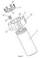
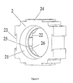
- a battery connection device including a connection block 2 that, made of insulating material, is positioned at an electrode end of a battery 1; the connection block 2 is provided at both ends with a series connection mechanism, respectively, and at all sides with a parallel connection mechanism, respectively; the parallel connection device refers to two dovetail grooves 23s and two dovetail blocks 24s positioned at four sides of the connection block 2; the series connection mechanism refers to a first slot 21 and a second slot 22 provided on two head faces of the connection block 2, the first slot 21 being for the battery 1 to be inserted directly, the second slot 22 being provided inside with the conductive slice 3; between the first slot 21 and the second slot 22 is positioned a spacer ring 25; the spacer ring 25 is integrated with the connection block 2, and provided at the center with a through hole 26; the conductive slice 3 is cut out at the center; the cut-out part is provided with two contact slices 31 s protruding toward the first slot 21;
- the U-form leading out slice 33 is adopted for leading out the conductive slice 3 to the fitting face of the dovetail groove 23 or the dovetail block 24, so as to make the two batteries 1s electrically connected in parallel through the connection block 2.
- the connection block 2 In practice, however, there are still other various designs to realize such an electrical connection when in parallel, which are all within the scope of protection of the invention.
- connection block 2 and its conductive slice 3 the invention can make each unit battery 1 connected modularly in series or parallel like a building block; and the battery set obtained from this connection does not further need electrode connection by welding or battery fixing by assembling; the invention not only is convenient for operation as well as safe and reliable, but also allows arbitrary combination, which can meet the voltage and capacity requirements of various storage batteries and battery sets.
Landscapes
- Chemical & Material Sciences (AREA)
- Chemical Kinetics & Catalysis (AREA)
- Electrochemistry (AREA)
- General Chemical & Material Sciences (AREA)
- Connection Of Batteries Or Terminals (AREA)
- Battery Mounting, Suspending (AREA)
- Coupling Device And Connection With Printed Circuit (AREA)
- Handcart (AREA)
Claims (7)
- Batterie-Verbindungsvorrichtung, wobei die Batterie-Verbindungsvorrichtung einen Verbindungsblock (2) aufweist, der aus Isoliermaterial besteht und an einem Elektrodenende einer Batterie (1) angeordnet ist; wobei der Verbindungsblock (2) an beiden Enden jeweils mit einer Reihenschaltungseinrichtung und auf allen Seiten jeweils mit einer Parallelschaltungseinrichtung bereitgestellt wird; wobei die Reihenschaltungseinrichtung innen mit einer leitfähigen Scheibe (3) bereitgestellt wird, die mit dem Elektrodenende der Batterie (1) elektrisch verbunden ist; wobei die leitfähige Scheibe (3) weiterhin zu einer Passfläche der Parallelschaltungseinrichtung herausgeführt wird, so dass die leitfähigen Scheiben (3s) auf den zwei Verbindungsblöcken (2) elektrisch miteinander verbunden sind, wenn die jeweils mit dem Verbindungsblock (2) versehenen Batterien (1 s) parallel zueinander sind.
- Batterie-Verbindungsvorrichtung nach Anspruch 1, wobei sich die Reihenschaltungseinrichtung auf einen ersten Schlitz (21) und einen zweiten Schlitz (22) bezieht, die auf zwei Kopfflächen des Verbindungsblocks (2) bereitgestellt werden, wobei der erste Schlitz (21) dem direkten Einsetzen der Batterie (1) in denselben dient, während der zweite Schlitz (22) innen mit der leitfähigen Scheibe (3) bereitgestellt wird; wobei die leitfähige Scheibe (3) mit der Batterie (1) im ersten Schlitz (21) elektrisch verbunden ist; und wobei das Elektrodenende einer weiteren Batterie (1) zur Herstellung einer Reihenschaltung in den zweiten Schlitz (22) der leitfähigen Scheibe (3) eingesetzt wird.
- Batterie-Verbindungsvorrichtung nach Anspruch 2, wobei sich die Parallelschaltungsvorrichtung sich auf zwei Schwalbenschwanznuten (23s) und zwei Schwalbenschwanzblöcke (24s) bezieht, die jeweils auf vier Seiten des Verbindungsblocks (2) angeordnet sind; wobei die leitfähige Scheibe (3) jeweils zu einer Passfläche der Schwalbenschwanznut (23) oder des Schwalbenschwanzblocks (24) herausgeführt wird; und wobei die mehreren Batterien (1s), die auf gleiche Weise mit dem Verbindungsblock (2) und der leitfähigen Scheibe (3) bereitgestellt werden, zur Herstellung einer Parallelschaltung durch das Einsetzen durch die Schwalbenschwanznut (23) und den Schwalbenschwanzblock (24) befestigt werden, und über die leitfähige Scheibe (3) elektrisch miteinander verbunden werden.
- Batterie-Verbindungsvorrichtung nach Anspruch 2 oder 3, wobei ein Abstandsring (25) zwischen dem ersten Schlitz (21) und dem zweiten Schlitz (22) angeordnet ist; wobei der Abstandsring (25) mit dem Verbindungsblock (2) baulich vereinigt ist und in der Mitte mit einem Durchgangsloch (26) bereitgestellt wird; wobei die leitfähige Scheibe (3) in der Mitte ausgeschnitten ist; wobei der ausgeschnittene Teil mit zwei Kontaktteilen (31s) bereitgestellt wird, die zum ersten Schlitz (21) hin hervorragen; wobei der Kontaktteil (31) durch Schweißen über das Durchgangsloch (26) mit der in den ersten Schlitz (21) eingesetzten Batterie (1) verbunden ist; und wobei der Verbindungsblock (2) mit Hilfe des zwischen der leitfähigen Scheibe (3) und der Batterie (1) festgeklemmten Abstandsrings (25) bezüglich der Batterie (1) befestigt wird.
- Batterie-Verbindungsvorrichtung nach Anspruch 4, wobei die leitfähige Scheibe (3) am Umfang mit mehreren nach außen gebogenen Klemmblättern (32s) bereitgestellt wird; und wobei die Batterie (1), die in den zweiten Schlitz (22) eingesetzt wird, der mit der leitfähigen Scheibe (3) bereitgestellt wird, durch das Klemmblatt (32) sowohl straff festgeklemmt und befestigt als auch elektrisch verbunden wird.
- Batterie-Verbindungsvorrichtung nach Anspruch 5, wobei zwischen der Passfläche der Schwalbenschwanznut (23) oder des Schwalbenschwanzblocks (24) und dem Klemmblatt (32) ein U-förmiger herausführender Teil (33) eingesetzt ist, dessen einer Anschlussstift zwischen Seitenwänden des Klemmblatts (32) und des zweiten Schlitzes (22) angeordnet und mit dem Klemmblatt (32) elektrisch verbunden ist, während sein anderer Anschlussstift auf der Passfläche der Schwalbenschwanznut (23) oder des Schwalbenschwanzblocks (24) angeordnet ist; und wobei ein Anschlussstift des U-förmigen herausführenden Teils (33), der auf der Passfläche der Schwalbenschwanznut (23) oder des Schwalbenschwanzblocks (24) angeordnet ist, zur Herstellung einer Parallelschaltung mit einem Anschlussstift des U-förmigen herausführenden Teils (33), der an einem anderen Verbindungsblocks (2) angeordnet ist, elektrisch verbunden wird.
- Batterie-Verbindungsvorrichtung nach Anspruch 6, wobei die zwei Anschlussstifte des U-förmigen herausführenden Teils (33) jeweils mit einem nach außen konvexen elastischen Teil (34) bereitgestellt werden.
Applications Claiming Priority (1)
| Application Number | Priority Date | Filing Date | Title |
|---|---|---|---|
| CN2008101684972A CN101369649B (zh) | 2008-09-30 | 2008-09-30 | 电池连接装置 |
Publications (2)
| Publication Number | Publication Date |
|---|---|
| EP2169740A1 EP2169740A1 (de) | 2010-03-31 |
| EP2169740B1 true EP2169740B1 (de) | 2011-04-13 |
Family
ID=40413345
Family Applications (1)
| Application Number | Title | Priority Date | Filing Date |
|---|---|---|---|
| EP09171415A Active EP2169740B1 (de) | 2008-09-30 | 2009-09-25 | Batterie-Verbindungsvorrichtung |
Country Status (9)
| Country | Link |
|---|---|
| US (1) | US7959457B2 (de) |
| EP (1) | EP2169740B1 (de) |
| JP (1) | JP5222262B2 (de) |
| KR (1) | KR101603132B1 (de) |
| CN (1) | CN101369649B (de) |
| AT (1) | ATE505821T1 (de) |
| AU (1) | AU2009222585B2 (de) |
| DE (1) | DE602009001079D1 (de) |
| IL (1) | IL201040A (de) |
Families Citing this family (45)
| Publication number | Priority date | Publication date | Assignee | Title |
|---|---|---|---|---|
| DE102011078636A1 (de) | 2011-07-05 | 2013-01-10 | Siemens Aktiengesellschaft | Überlastauslöser, insbesondere für einen Leistungsschalter |
| FR2978552B1 (fr) | 2011-07-29 | 2014-08-08 | Univ Limoges | Utilisation de nanoparticules d'or fonctionnalisees pour le dosage de l'uranium |
| CN102354734A (zh) * | 2011-09-05 | 2012-02-15 | 山东驰翔新能源科技有限公司 | 一种拆卸式组合连接片 |
| CN102394284B (zh) * | 2011-11-17 | 2013-11-20 | 茵卡动力系统(上海)有限公司 | 一种新能源汽车动力电池组 |
| CN103515565A (zh) * | 2012-06-29 | 2014-01-15 | 王怀云 | 圆柱形单体电池串联连接方法 |
| CN102751456A (zh) * | 2012-07-19 | 2012-10-24 | 八叶(厦门)新能源科技有限公司 | 电池支架 |
| USD720293S1 (en) * | 2012-10-02 | 2014-12-30 | North American Rescue, Llc | Battery connection adapter used with a portable battery |
| CN103280548A (zh) * | 2013-01-16 | 2013-09-04 | 许祎凡 | 电池连接装置以及应用该电池连接装置的电池组件 |
| US9437954B2 (en) * | 2013-04-26 | 2016-09-06 | Interconnect Devices, Inc. | Series connector |
| CN104253289B (zh) * | 2013-06-28 | 2017-06-09 | 王怀云 | 动力电池模块散热单元及动力电池散热模组 |
| CN103545468B (zh) * | 2013-10-14 | 2017-02-08 | 飞毛腿(福建)电子有限公司 | 一种电芯支架 |
| FR3013900B1 (fr) * | 2013-11-22 | 2015-12-11 | Blue Solutions | Module de stockage d'energie, comprenant une pluralite d'ensembles de stockage d'energie |
| CN103811709B (zh) * | 2014-01-30 | 2016-09-28 | 苏州安靠电源有限公司 | 一种圆柱单体连接装置 |
| CN105514338A (zh) * | 2016-01-29 | 2016-04-20 | 江苏海四达电源股份有限公司 | 一种圆柱形电池的组合连接装置 |
| CN105870538A (zh) * | 2016-05-18 | 2016-08-17 | 南京创源天地动力科技有限公司 | 一种电动汽车电池组热管理结构 |
| CN105932357A (zh) * | 2016-05-18 | 2016-09-07 | 南京创源天地动力科技有限公司 | 一种电动汽车电池组热管理液冷结构 |
| CN106229452A (zh) * | 2016-08-31 | 2016-12-14 | 河南新太行电源股份有限公司 | 一种整体卡板电池弹性连接装置 |
| DE102016219302A1 (de) * | 2016-10-05 | 2018-04-05 | Continental Automotive Gmbh | Energiezellenhaltevorrichtung für ein Kraftfahrzeug |
| CN106935910B (zh) * | 2017-02-22 | 2019-03-22 | 张家港清研首创再制造科技有限公司 | 一种新型储能用圆柱锂电池免焊接成组装置 |
| CN106876642A (zh) * | 2017-03-21 | 2017-06-20 | 河南锂想动力科技有限公司 | 一种电池连接装置 |
| US10263236B2 (en) | 2017-05-18 | 2019-04-16 | Ford Global Technologies, Llc | Battery cell securing assembly and method |
| CN107425164A (zh) * | 2017-06-30 | 2017-12-01 | 苏州安靠电源有限公司 | 电池连接支架 |
| CN107240667A (zh) * | 2017-06-30 | 2017-10-10 | 苏州安靠电源有限公司 | 一种电池串联片 |
| CN107195827A (zh) * | 2017-06-30 | 2017-09-22 | 苏州安靠电源有限公司 | 电池模组和大容量电池 |
| CN108054299A (zh) * | 2017-10-19 | 2018-05-18 | 金山电化工业(惠州)有限公司 | 一种可串联的特种电池 |
| DE102017219768B4 (de) * | 2017-11-07 | 2021-07-15 | Lion Smart Gmbh | Verfahren zum Herstellen einer Kontaktplatte für einen Batteriestapel, Kontaktplatte für einen Batteriestapel sowie Batteriestapel |
| CN108832069A (zh) * | 2018-08-27 | 2018-11-16 | 苏州安靠电源有限公司 | 电池模组 |
| CN109192914B (zh) * | 2018-10-23 | 2023-11-14 | 哈尔滨智明科技有限公司 | 一种基于动力电池串联连接的装置 |
| CN111180646A (zh) * | 2018-11-09 | 2020-05-19 | 王怀云 | 实现圆柱形电池串联和并联连接的复合导电片 |
| AT521379B1 (de) * | 2018-11-19 | 2020-01-15 | Raiffeisenlandesbank Oberoesterreich Ag | Kontaktierungsvorrichtung |
| KR102745421B1 (ko) | 2018-12-18 | 2024-12-20 | 주식회사 엘지에너지솔루션 | 전지셀 커넥터 및 이를 이용하여 연결되는 전지셀 구조체 |
| CN209045657U (zh) * | 2018-12-26 | 2019-06-28 | 宁德时代新能源科技股份有限公司 | 电池模组 |
| CN109830637A (zh) * | 2019-01-16 | 2019-05-31 | 苏州安靠电源有限公司 | 一种电池串联组件和电池模组 |
| CN110943193B (zh) * | 2019-12-30 | 2025-07-29 | 惠州市伟江实业有限公司 | 锂电池模组 |
| CN111554864B (zh) * | 2020-05-26 | 2025-05-16 | 路华电子科技(汕尾)有限公司 | 一种锂电池单体以及包含该锂电池单体的锂电池组 |
| CN112714511A (zh) * | 2020-12-24 | 2021-04-27 | 台州础能环境科技有限公司 | 可轴向延伸的模块化电加热装置 |
| CN114142132A (zh) * | 2021-11-03 | 2022-03-04 | 汪波 | 一种圆柱形电池的封装结构、圆柱形电池、电池组及其制造方法 |
| CN117293457A (zh) * | 2022-06-16 | 2023-12-26 | 哈尔滨子沐新能源科技有限公司 | 六边形电池模块拼装框架 |
| CN117293456A (zh) * | 2022-06-16 | 2023-12-26 | 哈尔滨子沐新能源科技有限公司 | 一种具有自锁结构的电池模块拼装框架 |
| CN115621666B (zh) * | 2022-11-07 | 2024-11-26 | 哈尔滨理工大学 | 一种基于插接导电片的电池连接结构及电池模块 |
| CN115621648B (zh) * | 2022-11-07 | 2024-08-27 | 哈尔滨理工大学 | 一种双凸极电池连接结构及电池模块 |
| FR3143211A1 (fr) * | 2022-12-13 | 2024-06-14 | Inphenix System | Module pour l’assemblage de cellules electriques |
| EP4557482A4 (de) * | 2022-12-16 | 2026-04-15 | Lg Energy Solution Ltd | Batteriepack und fahrzeug damit |
| CN118818332A (zh) * | 2023-04-17 | 2024-10-22 | 宁德时代新能源科技股份有限公司 | 测试机构、电池测试系统及电池生产系统 |
| CN116581483B (zh) * | 2023-05-26 | 2026-01-02 | 深圳尼索科连接技术股份有限公司 | 便捷式导电连接结构 |
Family Cites Families (16)
| Publication number | Priority date | Publication date | Assignee | Title |
|---|---|---|---|---|
| US4394059A (en) * | 1981-08-03 | 1983-07-19 | Amp Incorporated | Connector of a type used with dry cell batteries and manufacturing method |
| JPH10106520A (ja) * | 1996-09-26 | 1998-04-24 | Matsushita Electric Ind Co Ltd | 蓄電池電源装置 |
| JP2000100413A (ja) * | 1998-09-25 | 2000-04-07 | Sanyo Electric Co Ltd | 電気エネルギー蓄積素子及びその集合体 |
| JP2001256949A (ja) * | 2000-03-10 | 2001-09-21 | Toshiba Battery Co Ltd | 電池モジュール |
| ES2179734B1 (es) * | 2000-06-13 | 2004-04-01 | SOCIEDAD ESPAñOLA DEL ACUMULADOR TUDOR, S.A. | Baterias de acumuladores electricos. |
| JP4127501B2 (ja) * | 2002-11-19 | 2008-07-30 | 松下電器産業株式会社 | 電池間接続構造および電池モジュール並びに電池パック |
| JP4566544B2 (ja) * | 2003-10-15 | 2010-10-20 | 本田技研工業株式会社 | 蓄電装置 |
| JP2005123069A (ja) * | 2003-10-17 | 2005-05-12 | Sanyo Electric Co Ltd | 組電池 |
| JP5036971B2 (ja) * | 2004-10-08 | 2012-09-26 | 本田技研工業株式会社 | バッテリボックス構造 |
| JP2006147319A (ja) * | 2004-11-18 | 2006-06-08 | Sanyo Electric Co Ltd | 電源装置 |
| JP5005183B2 (ja) * | 2005-04-14 | 2012-08-22 | パナソニック株式会社 | 電池間接続構造 |
| JP2006318676A (ja) * | 2005-05-10 | 2006-11-24 | Sanyo Electric Co Ltd | 電池モジュール |
| JP4791076B2 (ja) * | 2005-05-13 | 2011-10-12 | 本田技研工業株式会社 | バッテリボックスの冷却構造 |
| KR100930474B1 (ko) * | 2005-12-08 | 2009-12-09 | 주식회사 엘지화학 | 전지모듈 제조용 조립식 스페이서 |
| US8795877B2 (en) * | 2007-05-31 | 2014-08-05 | Lg Chem, Ltd. | Electrical connecting member of assembling type and secondary battery pack containing the same |
| CN201270266Y (zh) * | 2008-09-30 | 2009-07-08 | 赛恩斯能源科技有限公司 | 电池连接装置 |
-
2008
- 2008-09-30 CN CN2008101684972A patent/CN101369649B/zh active Active
-
2009
- 2009-08-28 US US12/461,943 patent/US7959457B2/en active Active
- 2009-09-17 IL IL201040A patent/IL201040A/en active IP Right Grant
- 2009-09-25 AT AT09171415T patent/ATE505821T1/de not_active IP Right Cessation
- 2009-09-25 DE DE602009001079T patent/DE602009001079D1/de active Active
- 2009-09-25 EP EP09171415A patent/EP2169740B1/de active Active
- 2009-09-29 KR KR1020090092260A patent/KR101603132B1/ko not_active Expired - Fee Related
- 2009-09-29 JP JP2009224838A patent/JP5222262B2/ja active Active
- 2009-10-06 AU AU2009222585A patent/AU2009222585B2/en not_active Ceased
Also Published As
| Publication number | Publication date |
|---|---|
| JP5222262B2 (ja) | 2013-06-26 |
| KR101603132B1 (ko) | 2016-03-14 |
| IL201040A0 (en) | 2010-06-16 |
| AU2009222585A1 (en) | 2010-04-15 |
| JP2010086965A (ja) | 2010-04-15 |
| US7959457B2 (en) | 2011-06-14 |
| CN101369649B (zh) | 2010-06-02 |
| CN101369649A (zh) | 2009-02-18 |
| KR20100036992A (ko) | 2010-04-08 |
| AU2009222585B2 (en) | 2014-10-09 |
| IL201040A (en) | 2013-02-28 |
| EP2169740A1 (de) | 2010-03-31 |
| ATE505821T1 (de) | 2011-04-15 |
| US20100105239A1 (en) | 2010-04-29 |
| DE602009001079D1 (de) | 2011-05-26 |
Similar Documents
| Publication | Publication Date | Title |
|---|---|---|
| EP2169740B1 (de) | Batterie-Verbindungsvorrichtung | |
| EP2648243B1 (de) | Batteriemodul | |
| JP2014229615A (ja) | バッテリーモジュール | |
| US20210257704A1 (en) | Cell module | |
| DE69524894D1 (de) | Prismatische hochleistungsfähige Zelle | |
| KR101684349B1 (ko) | 보호회로모듈 케이스를 포함하는 전지팩 | |
| JP2009231138A (ja) | 電池パック | |
| EP4358654A3 (de) | Flexible schaltung mit einer sicherung, sammelschienenhalter mit einer einführungsstruktur, elektrische leitungsanordnung mit einer sammelschiene und batterie damit | |
| US20240079749A1 (en) | Power source device and method for manufacturing same | |
| US7466103B2 (en) | Battery module | |
| CN208605971U (zh) | 一种具有无缝对接功能的硬灯条 | |
| CN106571669B (zh) | 电池切换装置 | |
| CN215377517U (zh) | 一种锂离子电池胶态电芯 | |
| KR102319501B1 (ko) | 조립이 용이한 배터리 파워 팩 | |
| CN110622340A (zh) | 电池组件以及电池组件的制造方法 | |
| CN209016161U (zh) | 连接支架及电池模组 | |
| CN114530662A (zh) | 一种加热膜、电池模组及电池包 | |
| KR101741704B1 (ko) | 배터리 팩의 단자 연결 유닛 및 그에 의한 배터리 팩의 연결 방법 | |
| CN208400963U (zh) | 适用于锂离子电池的安全结构 | |
| CN220021540U (zh) | Ccs组件及电池模组 | |
| US10396340B2 (en) | Device and method for making a battery safe | |
| KR102461786B1 (ko) | 간소화된 리드 센싱바 용접 조립체 및 이를 갖는 배터리 모듈 | |
| CN205452462U (zh) | 一种软包锂离子储能动力电池pack装置 | |
| CN104681757A (zh) | 集合电池的电池架结构 | |
| CN220510301U (zh) | 插拔式接电端子件及灯具 |
Legal Events
| Date | Code | Title | Description |
|---|---|---|---|
| PUAI | Public reference made under article 153(3) epc to a published international application that has entered the european phase |
Free format text: ORIGINAL CODE: 0009012 |
|
| AK | Designated contracting states |
Kind code of ref document: A1 Designated state(s): AT BE BG CH CY CZ DE DK EE ES FI FR GB GR HR HU IE IS IT LI LT LU LV MC MK MT NL NO PL PT RO SE SI SK SM TR |
|
| 17P | Request for examination filed |
Effective date: 20100928 |
|
| GRAP | Despatch of communication of intention to grant a patent |
Free format text: ORIGINAL CODE: EPIDOSNIGR1 |
|
| GRAS | Grant fee paid |
Free format text: ORIGINAL CODE: EPIDOSNIGR3 |
|
| GRAA | (expected) grant |
Free format text: ORIGINAL CODE: 0009210 |
|
| AK | Designated contracting states |
Kind code of ref document: B1 Designated state(s): AT BE BG CH CY CZ DE DK EE ES FI FR GB GR HR HU IE IS IT LI LT LU LV MC MK MT NL NO PL PT RO SE SI SK SM TR |
|
| REG | Reference to a national code |
Ref country code: GB Ref legal event code: FG4D |
|
| REG | Reference to a national code |
Ref country code: CH Ref legal event code: EP |
|
| REG | Reference to a national code |
Ref country code: IE Ref legal event code: FG4D |
|
| REF | Corresponds to: |
Ref document number: 602009001079 Country of ref document: DE Date of ref document: 20110526 Kind code of ref document: P |
|
| REG | Reference to a national code |
Ref country code: DE Ref legal event code: R096 Ref document number: 602009001079 Country of ref document: DE Effective date: 20110526 |
|
| REG | Reference to a national code |
Ref country code: NL Ref legal event code: T3 |
|
| LTIE | Lt: invalidation of european patent or patent extension |
Effective date: 20110413 |
|
| PG25 | Lapsed in a contracting state [announced via postgrant information from national office to epo] |
Ref country code: PT Free format text: LAPSE BECAUSE OF FAILURE TO SUBMIT A TRANSLATION OF THE DESCRIPTION OR TO PAY THE FEE WITHIN THE PRESCRIBED TIME-LIMIT Effective date: 20110816 Ref country code: NO Free format text: LAPSE BECAUSE OF FAILURE TO SUBMIT A TRANSLATION OF THE DESCRIPTION OR TO PAY THE FEE WITHIN THE PRESCRIBED TIME-LIMIT Effective date: 20110713 Ref country code: HR Free format text: LAPSE BECAUSE OF FAILURE TO SUBMIT A TRANSLATION OF THE DESCRIPTION OR TO PAY THE FEE WITHIN THE PRESCRIBED TIME-LIMIT Effective date: 20110413 Ref country code: SE Free format text: LAPSE BECAUSE OF FAILURE TO SUBMIT A TRANSLATION OF THE DESCRIPTION OR TO PAY THE FEE WITHIN THE PRESCRIBED TIME-LIMIT Effective date: 20110413 Ref country code: LT Free format text: LAPSE BECAUSE OF FAILURE TO SUBMIT A TRANSLATION OF THE DESCRIPTION OR TO PAY THE FEE WITHIN THE PRESCRIBED TIME-LIMIT Effective date: 20110413 |
|
| PG25 | Lapsed in a contracting state [announced via postgrant information from national office to epo] |
Ref country code: ES Free format text: LAPSE BECAUSE OF FAILURE TO SUBMIT A TRANSLATION OF THE DESCRIPTION OR TO PAY THE FEE WITHIN THE PRESCRIBED TIME-LIMIT Effective date: 20110724 Ref country code: GR Free format text: LAPSE BECAUSE OF FAILURE TO SUBMIT A TRANSLATION OF THE DESCRIPTION OR TO PAY THE FEE WITHIN THE PRESCRIBED TIME-LIMIT Effective date: 20110714 Ref country code: IS Free format text: LAPSE BECAUSE OF FAILURE TO SUBMIT A TRANSLATION OF THE DESCRIPTION OR TO PAY THE FEE WITHIN THE PRESCRIBED TIME-LIMIT Effective date: 20110813 Ref country code: AT Free format text: LAPSE BECAUSE OF FAILURE TO SUBMIT A TRANSLATION OF THE DESCRIPTION OR TO PAY THE FEE WITHIN THE PRESCRIBED TIME-LIMIT Effective date: 20110413 Ref country code: FI Free format text: LAPSE BECAUSE OF FAILURE TO SUBMIT A TRANSLATION OF THE DESCRIPTION OR TO PAY THE FEE WITHIN THE PRESCRIBED TIME-LIMIT Effective date: 20110413 Ref country code: LV Free format text: LAPSE BECAUSE OF FAILURE TO SUBMIT A TRANSLATION OF THE DESCRIPTION OR TO PAY THE FEE WITHIN THE PRESCRIBED TIME-LIMIT Effective date: 20110413 Ref country code: CY Free format text: LAPSE BECAUSE OF FAILURE TO SUBMIT A TRANSLATION OF THE DESCRIPTION OR TO PAY THE FEE WITHIN THE PRESCRIBED TIME-LIMIT Effective date: 20110413 Ref country code: BE Free format text: LAPSE BECAUSE OF FAILURE TO SUBMIT A TRANSLATION OF THE DESCRIPTION OR TO PAY THE FEE WITHIN THE PRESCRIBED TIME-LIMIT Effective date: 20110413 Ref country code: SI Free format text: LAPSE BECAUSE OF FAILURE TO SUBMIT A TRANSLATION OF THE DESCRIPTION OR TO PAY THE FEE WITHIN THE PRESCRIBED TIME-LIMIT Effective date: 20110413 |
|
| PG25 | Lapsed in a contracting state [announced via postgrant information from national office to epo] |
Ref country code: CZ Free format text: LAPSE BECAUSE OF FAILURE TO SUBMIT A TRANSLATION OF THE DESCRIPTION OR TO PAY THE FEE WITHIN THE PRESCRIBED TIME-LIMIT Effective date: 20110413 Ref country code: EE Free format text: LAPSE BECAUSE OF FAILURE TO SUBMIT A TRANSLATION OF THE DESCRIPTION OR TO PAY THE FEE WITHIN THE PRESCRIBED TIME-LIMIT Effective date: 20110413 |
|
| PLBE | No opposition filed within time limit |
Free format text: ORIGINAL CODE: 0009261 |
|
| STAA | Information on the status of an ep patent application or granted ep patent |
Free format text: STATUS: NO OPPOSITION FILED WITHIN TIME LIMIT |
|
| PG25 | Lapsed in a contracting state [announced via postgrant information from national office to epo] |
Ref country code: PL Free format text: LAPSE BECAUSE OF FAILURE TO SUBMIT A TRANSLATION OF THE DESCRIPTION OR TO PAY THE FEE WITHIN THE PRESCRIBED TIME-LIMIT Effective date: 20110413 Ref country code: SK Free format text: LAPSE BECAUSE OF FAILURE TO SUBMIT A TRANSLATION OF THE DESCRIPTION OR TO PAY THE FEE WITHIN THE PRESCRIBED TIME-LIMIT Effective date: 20110413 |
|
| 26N | No opposition filed |
Effective date: 20120116 |
|
| PG25 | Lapsed in a contracting state [announced via postgrant information from national office to epo] |
Ref country code: MC Free format text: LAPSE BECAUSE OF NON-PAYMENT OF DUE FEES Effective date: 20110930 |
|
| REG | Reference to a national code |
Ref country code: DE Ref legal event code: R097 Ref document number: 602009001079 Country of ref document: DE Effective date: 20120116 |
|
| REG | Reference to a national code |
Ref country code: IE Ref legal event code: MM4A |
|
| PG25 | Lapsed in a contracting state [announced via postgrant information from national office to epo] |
Ref country code: IE Free format text: LAPSE BECAUSE OF NON-PAYMENT OF DUE FEES Effective date: 20110925 |
|
| PG25 | Lapsed in a contracting state [announced via postgrant information from national office to epo] |
Ref country code: MT Free format text: LAPSE BECAUSE OF FAILURE TO SUBMIT A TRANSLATION OF THE DESCRIPTION OR TO PAY THE FEE WITHIN THE PRESCRIBED TIME-LIMIT Effective date: 20110413 Ref country code: MK Free format text: LAPSE BECAUSE OF FAILURE TO SUBMIT A TRANSLATION OF THE DESCRIPTION OR TO PAY THE FEE WITHIN THE PRESCRIBED TIME-LIMIT Effective date: 20110413 |
|
| PG25 | Lapsed in a contracting state [announced via postgrant information from national office to epo] |
Ref country code: SM Free format text: LAPSE BECAUSE OF FAILURE TO SUBMIT A TRANSLATION OF THE DESCRIPTION OR TO PAY THE FEE WITHIN THE PRESCRIBED TIME-LIMIT Effective date: 20110413 |
|
| PG25 | Lapsed in a contracting state [announced via postgrant information from national office to epo] |
Ref country code: LU Free format text: LAPSE BECAUSE OF NON-PAYMENT OF DUE FEES Effective date: 20110925 |
|
| PG25 | Lapsed in a contracting state [announced via postgrant information from national office to epo] |
Ref country code: BG Free format text: LAPSE BECAUSE OF FAILURE TO SUBMIT A TRANSLATION OF THE DESCRIPTION OR TO PAY THE FEE WITHIN THE PRESCRIBED TIME-LIMIT Effective date: 20110713 |
|
| PG25 | Lapsed in a contracting state [announced via postgrant information from national office to epo] |
Ref country code: TR Free format text: LAPSE BECAUSE OF FAILURE TO SUBMIT A TRANSLATION OF THE DESCRIPTION OR TO PAY THE FEE WITHIN THE PRESCRIBED TIME-LIMIT Effective date: 20110413 |
|
| PG25 | Lapsed in a contracting state [announced via postgrant information from national office to epo] |
Ref country code: HU Free format text: LAPSE BECAUSE OF FAILURE TO SUBMIT A TRANSLATION OF THE DESCRIPTION OR TO PAY THE FEE WITHIN THE PRESCRIBED TIME-LIMIT Effective date: 20110413 |
|
| REG | Reference to a national code |
Ref country code: CH Ref legal event code: PL |
|
| PG25 | Lapsed in a contracting state [announced via postgrant information from national office to epo] |
Ref country code: LI Free format text: LAPSE BECAUSE OF NON-PAYMENT OF DUE FEES Effective date: 20130930 Ref country code: CH Free format text: LAPSE BECAUSE OF NON-PAYMENT OF DUE FEES Effective date: 20130930 |
|
| REG | Reference to a national code |
Ref country code: FR Ref legal event code: PLFP Year of fee payment: 8 |
|
| REG | Reference to a national code |
Ref country code: DE Ref legal event code: R082 Ref document number: 602009001079 Country of ref document: DE Representative=s name: GULDE & PARTNER PATENT- UND RECHTSANWALTSKANZL, DE Ref country code: FR Ref legal event code: PLFP Year of fee payment: 9 Ref country code: DE Ref legal event code: R081 Ref document number: 602009001079 Country of ref document: DE Owner name: ANKAO (SUZHOU) ENERGY CO., LTD, CN Free format text: FORMER OWNER: CENS ENERGY-TECH CO., LTD., ZHEJIANG, CN |
|
| REG | Reference to a national code |
Ref country code: GB Ref legal event code: 732E Free format text: REGISTERED BETWEEN 20171019 AND 20171025 |
|
| REG | Reference to a national code |
Ref country code: NL Ref legal event code: PD Owner name: ANKAO (SUZHOU) ENERGY CO., LTD; CN Free format text: DETAILS ASSIGNMENT: CHANGE OF OWNER(S), ASSIGNMENT; FORMER OWNER NAME: CENS ENERGY-TECH CO., LTD. Effective date: 20171107 |
|
| REG | Reference to a national code |
Ref country code: FR Ref legal event code: TP Owner name: ANKAO (SUZHOU) ENERGY CO., LTD, CH Effective date: 20180124 |
|
| REG | Reference to a national code |
Ref country code: FR Ref legal event code: PLFP Year of fee payment: 10 |
|
| PGFP | Annual fee paid to national office [announced via postgrant information from national office to epo] |
Ref country code: DE Payment date: 20200929 Year of fee payment: 12 Ref country code: FR Payment date: 20200929 Year of fee payment: 12 Ref country code: GB Payment date: 20200930 Year of fee payment: 12 |
|
| REG | Reference to a national code |
Ref country code: DE Ref legal event code: R079 Ref document number: 602009001079 Country of ref document: DE Free format text: PREVIOUS MAIN CLASS: H01M0002100000 Ipc: H01M0050200000 |
|
| PGFP | Annual fee paid to national office [announced via postgrant information from national office to epo] |
Ref country code: NL Payment date: 20200928 Year of fee payment: 12 |
|
| PGFP | Annual fee paid to national office [announced via postgrant information from national office to epo] |
Ref country code: IT Payment date: 20200928 Year of fee payment: 12 |
|
| REG | Reference to a national code |
Ref country code: DE Ref legal event code: R119 Ref document number: 602009001079 Country of ref document: DE |
|
| REG | Reference to a national code |
Ref country code: NL Ref legal event code: MM Effective date: 20211001 |
|
| GBPC | Gb: european patent ceased through non-payment of renewal fee |
Effective date: 20210925 |
|
| PG25 | Lapsed in a contracting state [announced via postgrant information from national office to epo] |
Ref country code: NL Free format text: LAPSE BECAUSE OF NON-PAYMENT OF DUE FEES Effective date: 20211001 |
|
| PG25 | Lapsed in a contracting state [announced via postgrant information from national office to epo] |
Ref country code: GB Free format text: LAPSE BECAUSE OF NON-PAYMENT OF DUE FEES Effective date: 20210925 Ref country code: FR Free format text: LAPSE BECAUSE OF NON-PAYMENT OF DUE FEES Effective date: 20210930 Ref country code: DE Free format text: LAPSE BECAUSE OF NON-PAYMENT OF DUE FEES Effective date: 20220401 |
|
| PG25 | Lapsed in a contracting state [announced via postgrant information from national office to epo] |
Ref country code: IT Free format text: LAPSE BECAUSE OF NON-PAYMENT OF DUE FEES Effective date: 20210925 |