EP2169239B1 - Klemme - Google Patents
Klemme Download PDFInfo
- Publication number
- EP2169239B1 EP2169239B1 EP08777569.8A EP08777569A EP2169239B1 EP 2169239 B1 EP2169239 B1 EP 2169239B1 EP 08777569 A EP08777569 A EP 08777569A EP 2169239 B1 EP2169239 B1 EP 2169239B1
- Authority
- EP
- European Patent Office
- Prior art keywords
- arm
- clamp
- support member
- connection member
- state
- Prior art date
- Legal status (The legal status is an assumption and is not a legal conclusion. Google has not performed a legal analysis and makes no representation as to the accuracy of the status listed.)
- Active
Links
Images


Classifications
-
- F—MECHANICAL ENGINEERING; LIGHTING; HEATING; WEAPONS; BLASTING
- F16—ENGINEERING ELEMENTS AND UNITS; GENERAL MEASURES FOR PRODUCING AND MAINTAINING EFFECTIVE FUNCTIONING OF MACHINES OR INSTALLATIONS; THERMAL INSULATION IN GENERAL
- F16B—DEVICES FOR FASTENING OR SECURING CONSTRUCTIONAL ELEMENTS OR MACHINE PARTS TOGETHER, e.g. NAILS, BOLTS, CIRCLIPS, CLAMPS, CLIPS OR WEDGES; JOINTS OR JOINTING
- F16B2/00—Friction-grip releasable fastenings
- F16B2/02—Clamps, i.e. with gripping action effected by positive means other than the inherent resistance to deformation of the material of the fastening
- F16B2/06—Clamps, i.e. with gripping action effected by positive means other than the inherent resistance to deformation of the material of the fastening external, i.e. with contracting action
- F16B2/10—Clamps, i.e. with gripping action effected by positive means other than the inherent resistance to deformation of the material of the fastening external, i.e. with contracting action using pivoting jaws
Definitions
- the present invention relates to a clamp that connects end portions of tubular members.
- a clamp for connecting end portions of two tubular members, a clamp is known that includes two annular members rotatably connected, engages a male screw member disposed in an end portion of one of the annular members with an end portion of another of the annular members, and fastens and fixes the end portions of the two tubular members by screwing the male screw member.
- a clamp coupling composed of two separated clamp hands is proposed (for example, refer to Patent Document 1). More specifically, there is proposed a clamp coupling, in which a rib portion having an opening in an end portion of each of two clamp hands is formed, the clamp coupling being fixed by a bolt member inserted into the opening and a nut member screwed on the bolt member.
- Patent Document 1 Japanese Unexamined Patent Application Publication No. H8-14454
- the object of the present invention is providing a clamp that can connect end portions of two tubular members by a simple operation.
- the present invention relates to a clamp for connecting a first tubular member having a circular flange formed in an end portion thereof with a second tubular member having a circular flange (512) formed in an end portion thereof, in a state where the circular flanges face each other and by covering outer peripheries of the circular flanges with the clamp, the clamp comprising: a support member; a first arm having an end pivotally supported by the support member ;a second arm disposed to face the first arm, having an end pivotally supported by the support member; a first concave portion formed on the first arm on a side facing the second arm and formed in a curved shape corresponding to the circular flanges to fit a first region along the outer peripheries of the circular flanges; a second concave portion formed on the second arm on a side facing the first arm and formed in a curved shape corresponding to the circular flanges to fit a second region along the outer peripheries of the circular flanges; a connection
- the clamp further includes a connecting portion transfer means that transfers the connection member.
- the connecting portion transfer means includes a female screw portion that is formed on the support member or on a member fixed to the support member, and a male screw portion that is screwed on the female screw portion, and has an end portion in contact with the connection member, and is configured so that the connection member is moved away from or toward the support member by rotating the male screw portion.
- a first end portion of the first arm on a side having the first concave portion opposite to the support member side and a second end portion of the second arm on a side having the second concave portion opposite to the support member side contact each other.
- a first end portion of the first arm on a side having the first concave portion opposite to the support member side and a second end portion of the second arm on a side having the second concave portion opposite to the support member side are spaced apart from each other, and a ratio of a length of the outer peripheries of the flanges disposed between the first end portion and the second end portion is no greater than 0.17 with respect to a length of the entire outer peripheries of the flanges.
- An object of the present invention is providing a clamp that can connect end portions of two tubular members by a simple operation.
- FIG. 1 is a planar view of a clamp 1 in an open state.
- FIG. 2 is a side view of the clamp 1 in an open state.
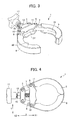
- FIG. 3 is a perspective view of the clamp 1 in an open state.
- FIG. 4 is a planar view of the clamp 1 in a closed state.
- the clamp 1 is, in a state where a first tubular member with a circular flange formed in an end portion thereof and a second tubular member with a circular flange formed in an end portion thereof are disposed such that the flanges thereof face each other, a clamp that connects by covering outer peripheries of the two flanges with a first arm and a second arm.
- the clamp 1 includes: a support member 3; a first arm 5 having a first end pivotably supported by the support member 3; a second arm 6 disposed to face the first arm 5, having a first end pivotably supported by the support member 3; a first long hole 7 as the first guide portion that is formed on the support member 3 side of the first arm 5; a second long hole 8 as the second guide portion that is formed on the support member 3 side of the second arm 6; and an connection member 11 including a first pin member 9 as the first engaging member inserted into and engaged with the first long hole 7 and a second pin member 10 as the second engaging member inserted into and engaged with the second long hole 8.
- the clamp 1 is configured so that the connection member 11 can move away from and/or move toward the support member 3.
- the clamp 1 includes a screw mechanism as the connecting portion transfer means that allows the connection member 11 to move as described above. More specifically, the clamp 1 includes a female screw portion 13a (not shown) that is formed on a nut 13 fixed to the support member 3 and a male screw portion 15 that is screwed on the female screw portion 13a and of which an end portion contacts the connection member 11.
- a grip portion 17 for rotating the male screw portion 15 is disposed in an end portion of the male screw portion 15 on an opposite side to the connection member 11.
- the support member 3 pivotably supports a first end of the first arm 5.
- the support member 3 pivotably supports a first end of the second arm 6.
- Portions of the support member 3 that pivotably support the first arm 5 and the second arm 6 respectively act as fulcrums for opening and closing action of the first arm 5 and the second arm 6 respectively.
- the nut 13 is fixed to the support member 3 on an opposite side to a side on which the first arm 5 and the second arm 6 are disposed.
- An opening (not shown), into which the male screw portion 15 that is screwed on the female screw portion 13a formed on the nut 13 is inserted, is formed in the support member 3.
- the male screw portion 15 is disposed on the support member 3 so as to penetrate the support member 3.
- the first end of the first arm 5 is pivotably supported by the support member 3.
- the second arm 6 is disposed to face the first arm 5 and the first end thereof is pivotably supported by the support member 3.
- the first arm 5 and the second arm 6 are each formed in a curved shape, such that sides facing each other are concave. More specifically, the first arm 5 and the second arm 6 are each formed in an arc-like shape along outer peripheries of the two flanges facing each other, to which the clamp 1 (described later) is to be attached.
- the first arm 5 includes a first concave portion 19, which is formed on a side facing the second arm 6, into which a part of the outer peripheries of the two flanges fits.
- the second arm 6 includes a second concave portion 20, which is formed on a side facing the first arm 5, into which a part of the outer peripheries of the two flanges fits.
- the first concave portion 19 and the second concave portion 20 are formed so that width thereof narrows as outer sides are approached from inner sides, the inner sides facing each other and the outer sides being opposite to the inner side.
- first concave portion 19 and the second concave portion 20 are each formed so as to make a distance between the two flanges smaller, as the two flanges that fit into the first concave portion 19 and the second concave portion 20 fit in more deeply.
- the first arm 5 and the second arm 6 are formed so that tips thereof contact each other in a case where the clamp 1 is in a closed state while the two flanges fit into the first concave portion 19 and the second concave portion 20. This can inhibit breakage of the flanges and the arms due to over-fastening.
- the first long hole 7 is formed in the first arm 5 on a support member 3 side.
- the second long hole 8 is formed in the second arm 6 on the support member 3 side.
- the first long hole 7 and the second long hole 8 are each formed to extend in a direction intersecting with a moving direction X of the connection member 11 (described later). More specifically, the first long hole 7 and the second long hole 8 are each formed so that a distance therebetween in a direction Y vertical to the moving direction X becomes greater with movement away from the support member 3.
- the first long hole 7 and the second long hole 8 are formed so that they are inclined towards each other, with the distance therebetween increasing with movement in a direction X1 with respect to the moving direction X.
- Speed of pivotal movement (opening and closing) of the first arm 5 and the second arm 6 is determined by angles between directions in which the first long hole 7 and the second long hole 8 extend respectively and the moving direction X. More specifically, in a case where the angles between the directions in which the first long hole 7 and the second long hole 8 extend respectively and the moving direction X is large, the speed of pivotal movement of the first arm 5 and the second arm 6 is large. In other words, the speed of opening and closing of the clamp 1 becomes greater in such a configuration. On the other hand, in a case where the angles between the directions in which the first long hole 7 and the second long hole 8 extend respectively and the moving direction X is small, the speed of pivotal movement of the first arm 5 and the second arm 6 is low. In other words, the speed of opening and closing of the clamp 1 becomes lower in such a configuration.
- length of each of the first long hole 7 and the second long hole 8 is determined by diameter of a flange for attaching, length of the support member 3 in a direction Y, angle between directions in which the first long hole 7 and the second long hole 8 extend respectively and the moving direction X, and the like.
- the first pin member 9 is inserted into and engaged with the first long hole 7.
- the second pin member 10 is inserted into and engaged with the second long hole 8.
- the first pin member 9 and the second pin member 10 are metallic cylindrical members.
- the first pin member 9 is inserted into the first long hole 7 and transfer thereof is guided by the first long hole 7.
- the second pin member 10 is inserted into the second long hole 8 and transfer thereof is guided by the second long hole 8.
- the first pin member 9 and the second pin member 10 are fixed at both ends in the direction Y of the connection member 11.
- connection member 11 fixes the first pin member 9 and the second pin member 10 while maintaining a distance therebetween.
- the connection member 11 is configured to be movable in the moving direction X while maintaining a distance in the direction Y between the first pin member 9 and the second pin member 10.
- connection member 11 An end portion of the male screw portion 15 contacts the support member 3 side of the connection member 11. As the male screw portion 15 is rotated, the end portion thereof moves in the moving direction X and moves the connection member that contacts the end portion 11 in the moving direction X. More specifically, the connection member 11 is moved toward X1 in the moving direction X away from the support member 3 by the male screw portion 15, and toward X2 in the moving direction X toward the support member 3 by the male screw portion 15.
- the clamp 1 By rotating the grip portion 17, the clamp 1 can be shifted from the open state shown in FIG. 1 to the closed state shown in FIG. 4 , and vice versa.
- an after mentioned attaching operation and a fastening operation are performed in a state where the third concave portion 22 contacts and is positioned at a predetermined position of the outer peripheries of the two flanges facing each other.
- the connection member 11 functions also as a positioning member. In this case, since the connection member 11 is positioned and fixed to the outer peripheries of the two flanges in the fastening operation, the connection member 11 may seem not to move; however, the connection member 11 obviously moves with respect to the support member 3.
- the screw mechanism consists of: the female screw portion 13a of the nut 13 fixed to the support member 3; the rod-like male screw portion 15 that is screwed on the female screw portion 13a and whose rotational axis is disposed parallel to the moving direction X; and the grip portion 17 that is disposed at an end portion of the male screw portion 15 on an opposite side to an connection member 11 side.
- the male screw portion 15 is rotated by rotating the grip portion 17.
- the nut 13, with the female screw portion 13a formed therein and on which the male screw portion 15 is screwed, is fixed to the support member 3, so that the length of the male screw portion 15 disposed between the support member 3 and the connection member 11 is changed by rotating the male screw portion 15 by way of the grip portion 17.
- an end portion of the male screw portion 15 moves in the moving direction X. That is, the connection member 11, with which an end portion of the male screw portion 15 is in contact, is moved in the moving direction X by rotating the grip portion 17.
- the configuration is such that the tubular member does not interfere with a rotating operation of the grip portion 17. This allows a preferable rotating operation (fastening operation) of the grip portion 17.
- maximum diameter of the grip portion there is essentially no limitation regarding maximum diameter of the grip portion.
- the maximum diameter of the grip portion 17 is only required to be no less than a diameter of the male screw portion 15 and is not particularly limited; however, the maximum diameter is preferably in a range from the diameter of the male screw portion 15 to a length in a width direction of the clamp 1 in a state where the first arm 5 and the second arm 6 are closed.
- the maximum diameter of the grip portion 17 can be, for example, 32 mm to 50 mm from the viewpoint of operability and size reduction. Since the maximum diameter of the grip portion 17 can be great as described above, the rotating operation (fastening operation) can be performed more preferably.
- steps for connecting a first tubular member 501 and a second tubular member 502 by way of the clamp 1 are described with reference to FIGS. 5 to 11 . More specifically, a process for connecting the first tubular member 501 and the second tubular member 502 by way of the clamp 1 in a state where a first flange 511 formed at an end portion of the first tubular member 501 and a second flange 512 formed at an end portion of the second tubular member 502 are disposed so as to face each other.
- FIG. 5 is a planar view of a state where the clamp 1 in an open state is positioned on a flange of a tubular member.
- FIG. 6 is a side view of a state where the clamp 1 in an open state is positioned on a flange of the tubular member.
- FIG. 7 is a side view of a state where the clamp 1 in an open state is positioned on a flange of the tubular member seen from a grip portion 17 side.
- FIG. 8 is a perspective view of a state where the clamp 1 in an open state is positioned on a flange of the tubular member.
- FIG. 9 is a perspective view of a state where the clamp 1 in the open state shown in FIG. 8 is being shifted to a closed state.
- FIG. 10 is a perspective view of a state where the clamp 1 in a closed state (connected state) is disposed so that arms thereof cover the flange of the tubular member.
- FIG. 11 is a planar view of a state where the clamp 1 in a closed state (connected state) is disposed so that arms thereof cover the flange of the tubular member.
- the clamp 1 in an open state is attached to the flanges 511 and 512. More specifically, the clamp 1 is positioned by fitting the third concave portion 22 formed on the connection member 11 at a predetermined position on outer peripheries of the two flanges 511 and 512 that face each other. In such a state, the first arm 5 and the second arm 6 are disposed at an outer side of the flanges 511 and 512 respectively, as shown in FIGS. 6 to 8 .
- first arm 5 and the second arm 6 are each disposed at a position such that, in a case where the first arm 5 and the second arm 6 pivotally move so as to approach each other, the first concave portion 19 formed on the first arm 5 and the second concave portion 20 formed on the second arm 6 fit the flanges 511 and 512 respectively.
- the grip portion 17 is rotated in a state where the flanges 511 and 512 fit the third concave portion 22 formed on the connection member 11.
- an end portion of the male screw portion 15 is moved toward X1 in the moving direction X. More specifically, by rotating the male screw portion 15 by rotating the grip portion 17, the male screw portion 15 screwed on the female screw portion 13a formed on the nut 13 is drawn toward the connection member 11 so that a length thereof on the connection member 11 side becomes longer. As a result, the connection member 11 is pushed out and moved toward X1 in the moving direction X, as shown in FIG. 9 .
- connection member 11 By moving the connection member 11 toward X1 in the moving direction X, the first pin member 9 and the second pin member 10 fixed to the connection member 11 are each moved toward X1 in the moving direction X while maintaining a distance therebetween. Since the first pin member 9 and the second pin member 10 are inserted into and engaged with the first long hole 7 and the second long hole 8 respectively, the first pin member 9 and the second pin member 10 are guided in a state of being inserted into the first long hole 7 and the second long hole 8 respectively.
- connection member 11 is further moved toward X1 in the moving direction X.
- first arm 5 and the second arm 6 are each pivotally moved to further approach each other.
- the clamp 1 is then shifted to a closed state as shown in FIGS. 10 and 11 .
- the clamp 1 in a closed state forms a substantially circular shape by the first arm 5, the second arm 6, and the connection member 11.
- the clamp 1 in a closed state is disposed so that the first arm 5, the second arm 6, and the connection member 11 are disposed to surround the outer peripheries of the flanges 511 and 512.
- a tip of the first arm 5 and a tip of the second arm 6 contact each other.
- the first arm 5 and the tip of the second arm 6 contact each other in a closed state, the first arm 5 and the second arm 6 can be inhibited from contacting the flanges 511 and 512 too strongly even in a case where the grip portion is rotated too strongly.
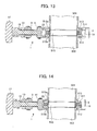
- FIG. 12 is a cross-sectional view of a state where a first tubular member and a second tubular member are disposed so that flanges thereof face each other.
- FIG. 13 is a cross-sectional view of a state where the clamp 1 is attached to outer peripheries of the flanges in FIG. 12 .
- FIG. 14 is a cross-sectional view of a state where the clamp 1 is further shifted to a closed state from a state shown in FIG. 13 .
- the first tubular member 501 and the second tubular member 502 are disposed so that the first flange 511 and the second flange 512, which are flange-shaped and formed in an end portion thereof respectively, face each other.
- the first tubular member 501 and the second tubular member 502 are disposed so as to face each other across a center ring 515 that is disposed such that both ends thereof are placed on a first step portion 515a formed in an end portion of the first tubular member 501 and a second step portion 515b formed in an end portion of the second tubular member 502.
- an O-shaped ring 513 that is elastically deformable is disposed in a state of being placed on an outer face of the center ring 515.
- connection member 11, the first arm 5 and the second arm 6 are attached to surround the outer peripheries of the flanges 511 and 512. More specifically, by rotating the grip portion 17 in a state where the third concave portion 22 formed on the connection member 11 is fitted at a predetermined position on the outer peripheries of the flanges 511 and 512, as described above, the first arm 5 and the second arm 6 are pivotally moved toward the flanges 511 and 512. As a result, the third concave portion 22, the first concave portion 19 and the second concave portion 20 are disposed to fit to the outer peripheral portions (outer end portions) of the flanges 511 and 512, as shown in FIG. 13 . In this state, the O-shaped ring 513 is not deformed and has a completely round cross-section.
- the first concave portion 19 and the second concave portion 20 fit as far as base portions of the flanges 511 and 512, as shown in FIG. 14 .
- the first concave portion 19, the second concave portion 20 and the third concave portion 22 are each formed so that width thereof narrows along a direction of an outer side from an inner side.
- the first concave portion 19, the second concave portion 20 and the third concave portion 22 are each formed so that a width thereof narrows in a direction of a bottom face thereof.
- the clamp 1 is strongly attached to the flanges 511 and 512.
- a force for narrowing a distance between the flanges 511 and 512 is applied to the flanges 511 and 512. This narrows a space formed at both ends of the center ring 515 and deforms the O-shaped ring 513 into an oval shape.
- the clamp 1 includes: the first arm 5 and the second arm 6 that are pivotably supported by the support member 3; the first long hole 7 and the second long hole 8 as guide portions that are formed in the first arm 5 and the second arm 6 respectively; and the connection member 11 provided with the first pin member 9 and the second pin member 10 engaging with the first long hole 7 and the second long hole 8 respectively, and is configured such that the first arm 5 and the second arm 6 are openable and closable by moving the connection member 11.
- the clamp 1 is easily opened and closed by moving the connecting portion by means of a predetermined connecting portion transfer means. Therefore, end portions of tubular members can be easily connected by means of the clamp 1.
- the first arm 5 and the second arm 6 can be opened and closed only by rotating the grip portion 17, an attaching operation and a fastening operation can be performed only from one side of the tubular members. This can easily attach and fasten the clamp 1 to the tubular members. Furthermore, since the clamp 1 can be attached and fastened to the tubular members only by rotating the grip portion 17, the attaching operation and the fastening operation of the clamp 1 can be performed with one hand. Such easy attaching and fastening can alleviate stress of an operator.
- the operator can perform the fastening operation in a state facing a lateral face of the tubular members, when rotating the grip portion 17 is rotated. This improves operability of the clamp 1 in the fastening process.
- the attaching operation and the fastening operation are performed in a state where the connection member 11 contacts and is positioned on a flange
- the first arm 5 and the second arm 6 can be inhibited from being fastened in a state of being misaligned from the flange.
- This can easily attach and fasten the clamp 1 to an accurate position by a simple operation.
- This also can inhibit leakage and the like that can occur in a case where the arms are fastened in a misaligned state.
- This also can inhibit breakage of the flange and the clamp 1 that can occur in a case where the arms are fastened in a misaligned state.
- the diameter of the grip portion 17 is essentially unlimited, the diameter of the grip portion 17 can be large. This can allow the operator to perform the fastening operation with a small force. Moreover, since the grip portion 17 can be formed in a size and a shape that suits a human hand, operability in the fastening operation can be further improved.
- the clamp 1 can be attached to and detached from a flange by a simple operation as described above, the clamp 1 can be preferably used in a factory and the like where a maintenance operation is required.
- the present invention is not limited thereto and can be carried out in various modes.
- the first long hole 7 and the second long hole 8 are described as a guide portion; however, the guide portion is not limited thereto and can be a concave portion.
- a protrusion formed on the connection member 11 can be exemplified.
- the first long hole 7 and the second long hole 8 as guide members are each formed so that a distance therebetween in a direction Y vertical to the moving direction X becomes greater with movement away from the support member 3; however, the present invention is not limited thereto.
- the first long hole 7 and the second long hole 8 as guide members can be each formed so that a distance therebetween in a direction Y vertical to the moving direction X becomes smaller with movement away from the support member 3.
- the female screw portion 13a is formed on the nut 13 that is connected to the support member 3; however, the present invention is not limited thereto and the female screw portion 13a can be formed directly on the support member 3.
- the grip portion 17 is fixed to an end portion of the male screw portion 15; however, the present invention is not limited thereto and the grip portion 17 can be made detachable. In this case, a single grip portion (member) can be used to fasten a plurality of clamps. Furthermore, since the grip portion 17 is detached in a state where the clamp 1 is fixed to a flange, space can be effectively used. Moreover, the clamp 1 can be reduced in cost.
- an operator rotates the grip portion 17 disposed in an end portion of the male screw portion 15 for rotating the male screw portion 17; however, the present invention is not limited thereto.
- the male screw portion 15 can be mechanically rotated by attaching a rotary drive device such as an electric drill to an end portion of the male screw portion 15.
- a screw mechanism is used as a connecting portion transfer means; however, the present invention is not limited thereto.
- a mechanism, a device and the like that can push the connection member 11 toward X1 in the moving direction X such as a cylinder mechanism, can be used as a connecting portion transfer means.
- a tip of the first arm 5 and a tip of the second arm 6 are formed to contact in a fastened state; however, the present invention is not limited thereto.
- a first end portion of the first arm on an opposite side to the support member side and a second end portion of the second arm on an opposite side to the support member side can be spaced apart from each other in a state where the first tubular member and the second tubular member are connected by a clamp.
- a ratio of a length of outer peripheries of the two flanges disposed between the first end portion and the second end portion can be configured to be no greater than 0.17 with respect to a length of the entire outer peripheries of the two flanges, and preferably in a range of 0.01 to 0.14.
- it can be configured such that an open angle formed by a line connecting a central point of the flange and the first end portion and a line connecting the central point and the second end portion is 0 to 60 degrees, preferably 5 to 50 degrees.
Landscapes
- Engineering & Computer Science (AREA)
- General Engineering & Computer Science (AREA)
- Mechanical Engineering (AREA)
- Clamps And Clips (AREA)
- Mutual Connection Of Rods And Tubes (AREA)
- Flanged Joints, Insulating Joints, And Other Joints (AREA)
- Supports For Pipes And Cables (AREA)
Claims (5)
- Klammer (1) zum Verbinden eines ersten röhrenförmigen Elements (501), das einen kreisförmigen Flansch (511) aufweist, der in einem Endabschnitt desselben gebildet ist, mit einem zweiten röhrenförmigen Element (502), das einen kreisförmigen Flansch (512) aufweist, der in einem Endabschnitt desselben gebildet ist, in einem Zustand, in dem die kreisförmigen Flansche (511, 512) einander gegenüberstehen und durch Abdecken der äußeren Randbereiche der kreisförmigen Flansche (511, 512) mit der Klammer (1), wobei die Klammer (1) Folgendes umfasst:ein Trägerelement (3);einen ersten Arm (5), der ein Ende aufweist, das von dem Trägerelement (3) schwenkbar getragen wird;einen zweiten Arm (6), der gegenüber dem ersten Arm (5) angeordnet ist und ein Ende aufweist, das von dem Trägerelement (3) schwenkbar getragen wird;einen ersten konkaven Abschnitt (19), der an dem ersten Arm (5) auf einer Seite, die dem zweiten Arm (6) gegenübersteht, gebildet ist und in einer gekrümmten Form gebildet ist, die den kreisförmigen Flanschen (511, 512) entspricht, um in einen ersten Bereich entlang den äußeren Randbereichen der kreisförmigen Flansche (511, 512) zu passen;einen zweiten konkaven Abschnitt (20), der an dem zweiten Arm (6) auf einer Seite, die dem ersten Arm (5) gegenübersteht, gebildet ist und in einer gekrümmten Form gebildet ist, die den kreisförmigen Flanschen (511, 512) entspricht, um in einen zweiten Bereich entlang den äußeren Randbereichen der kreisförmigen Flansche (511, 512) zu passen;ein Verbindungselement (11), das den ersten Arm (5) und den zweiten Arm (6) verbindet;dadurch gekennzeichnet, dass die Klammer (1) ferner Folgendes umfasst:einen ersten Führungsabschnitt (7), der in der Nähe des Endes des ersten Arms (5) gebildet ist und mit einem ersten Ende des Verbindungselements (11) durch ein erstes Eingriffselement (9) in Eingriff steht; undeinen zweiten Führungsabschnitt (8), der in der Nähe des Endes des zweiten Arms (6) gebildet ist und mit einem zweiten Ende des Verbindungselements (11) durch ein zweites Eingriffselement (10) in Eingriff steht;einen dritten konkaven Abschnitt (22), der an dem Verbindungselement (11) auf einer der Trägerelementseite gegenüberliegenden Seite gebildet ist, um in einen dritten Bereich entlang den äußeren Randbereichen der kreisförmigen Flansche (511, 512) zu passen;wobei das Verbindungselement (11) zu und von dem Trägerelement (3) bewegbar ist und dabei einen Abstand zwischen dem ersten Eingriffselement (9) und dem zweiten Eingriffselement (10) einhält, undwobei der erste Führungsabschnitt (7) und der zweite Führungsabschnitt (8) jeweils aus einem ersten Langloch (7) und einem zweiten Langloch (8) gebildet sind, so dass sich ein Abstand dazwischen in einer Richtung senkrecht zu einer Bewegungsrichtung des Verbindungselements (11) mit der sich von dem Trägerelement (3) entfernenden Bewegung vergrößert; und wobei für den Fall, dass sich das Verbindungselement (11) von dem Trägerelement (3) entfernt, der erste Arm (5) und der zweite Arm (6) jeweils schwenkbar bewegen, um sich einander zu nähern; für den Fall, dass sich das Verbindungselement (11) dem Trägerelement (3) nähert, sich der erste Arm (5) und der zweite Arm (6) jeweils schwenkbar bewegen, um sich voneinander zu entfernen.
- Klammer nach Anspruch 1, ferner umfassend ein Verbindungsabschnitt-Übertragungsmittel (13, 15, 17), welches das Verbindungselement (11) überträgt.
- Klammer nach Anspruch 2, wobei das Verbindungsabschnitt-Übertragungsmittel (13, 15, 17) einen Innengewindeabschnitt (13a), der auf dem Trägerelement (3) oder auf einem Element, das an dem Trägerelement (3) befestigt ist, gebildet ist, und einen Außengewindeabschnitt (15), der auf den Innengewindeabschnitt (13a) geschraubt wird und einen Endabschnitt in Kontakt mit dem Verbindungselement (11) aufweist und derart konfiguriert ist, dass das Verbindungselement (11) durch Drehen des Außengewindeabschnitts (15) von und zu dem Trägerelement (3) bewegt wird, umfasst.
- Klammer nach Anspruch 1, wobei in einem Zustand, in dem die Klammer (1) das erste röhrenförmige Element (501) und das zweite röhrenförmige Element (502) verbindet, ein erster Endabschnitt des ersten Arms (5) auf einer Seite, auf welcher der erste konkave Abschnitt (19) der Trägerelementseite gegenüberliegt, und ein zweiter Endabschnitt des zweiten Arms (6) auf einer Seite, auf welcher der zweite konkave Abschnitt (20) der Trägerelementseite gegenüberliegt, einander berühren.
- Klammer nach Anspruch 1, wobei, in einem Zustand, in dem die Klammer (1) das erste röhrenförmige Element (501) und das zweite röhrenförmige Element (502) verbindet, ein erster Endabschnitt des ersten Arms (5) auf einer Seite, auf welcher der erste konkave Abschnitt (19) der Trägerelementseite gegenüberliegt, und ein zweiter Endabschnitt des zweiten Arms (6) auf einer Seite, auf welcher der zweite konkave Abschnitt (20) der Trägerelementseite gegenüberliegt, voneinander beabstandet sind, und ein Verhältnis einer Länge der äußeren Randbereiche der kreisförmigen Flansche (511, 512), die zwischen dem ersten Endabschnitt und dem zweiten Endabschnitt angeordnet sind, im Verhältnis zu einer Länge der gesamten äußeren Randbereiche der kreisförmigen Flansche (511, 512) nicht größer als 0,17 ist.
Applications Claiming Priority (2)
| Application Number | Priority Date | Filing Date | Title |
|---|---|---|---|
| JP2007169498A JP5231760B2 (ja) | 2007-06-27 | 2007-06-27 | クランプ |
| PCT/JP2008/061512 WO2009001839A1 (ja) | 2007-06-27 | 2008-06-25 | クランプ |
Publications (3)
| Publication Number | Publication Date |
|---|---|
| EP2169239A1 EP2169239A1 (de) | 2010-03-31 |
| EP2169239A4 EP2169239A4 (de) | 2011-11-02 |
| EP2169239B1 true EP2169239B1 (de) | 2016-01-06 |
Family
ID=40185651
Family Applications (1)
| Application Number | Title | Priority Date | Filing Date |
|---|---|---|---|
| EP08777569.8A Active EP2169239B1 (de) | 2007-06-27 | 2008-06-25 | Klemme |
Country Status (4)
| Country | Link |
|---|---|
| US (1) | US20100207385A1 (de) |
| EP (1) | EP2169239B1 (de) |
| JP (1) | JP5231760B2 (de) |
| WO (1) | WO2009001839A1 (de) |
Families Citing this family (11)
| Publication number | Priority date | Publication date | Assignee | Title |
|---|---|---|---|---|
| EP4179997A3 (de) | 2015-06-08 | 2023-08-30 | Covidien LP | Befestigungsvorrichtung für chirurgische systeme und verfahren zur verwendung |
| US10072685B2 (en) * | 2016-02-12 | 2018-09-11 | Scott Boerman | Clip holding and release device |
| US20180340638A1 (en) * | 2017-05-25 | 2018-11-29 | Edwards Vacuum Llc | Clamps for fluid conduits |
| US10436362B2 (en) * | 2017-09-19 | 2019-10-08 | Mcelroy Manufacturing, Inc. | Clamp assembly |
| US10795146B2 (en) * | 2018-03-30 | 2020-10-06 | Celestron Acquisition, Llc | Smartphone adapter for imaging through optical devices |
| USD911158S1 (en) * | 2018-09-14 | 2021-02-23 | Doughty Engineering Limited | Clamp |
| USD920852S1 (en) * | 2019-05-06 | 2021-06-01 | Cake 0 emission AB | Electric motorcycle |
| USD944070S1 (en) | 2020-02-26 | 2022-02-22 | Edwards Vacuum Llc | Clamp |
| KR102524348B1 (ko) * | 2020-11-23 | 2023-04-24 | 강희양 | 배관연결클램프 |
| US20240206983A1 (en) * | 2022-12-21 | 2024-06-27 | Mako Surgical Corp. | Surgical Clamp Assembly For Fixing A Navigation Tracker To A Portion Of Bone |
| USD1070582S1 (en) * | 2023-09-01 | 2025-04-15 | Rockler Companies, Inc. | Clamp |
Family Cites Families (16)
| Publication number | Priority date | Publication date | Assignee | Title |
|---|---|---|---|---|
| DE1189323B (de) * | 1959-08-14 | 1965-03-18 | Fuba Antennenwerke Hans Kolbe | Schelle zur Befestigung sich kreuzender Staebe |
| JPS451837Y1 (de) * | 1965-08-03 | 1970-01-26 | ||
| JPS4931331Y1 (de) * | 1970-06-22 | 1974-08-24 | ||
| JPS5210274U (de) * | 1975-07-09 | 1977-01-24 | ||
| JPS53166119U (de) * | 1977-06-03 | 1978-12-26 | ||
| FR2469638A1 (fr) * | 1979-08-14 | 1981-05-22 | Commissariat Energie Atomique | Raccord autoverrouillable |
| JPS6326755Y2 (de) * | 1980-05-20 | 1988-07-20 | ||
| JPS5929123B2 (ja) * | 1980-09-30 | 1984-07-18 | 神鋼電機株式会社 | 緩衝クランプ装置 |
| US4568115A (en) * | 1983-04-20 | 1986-02-04 | Ladish Co. | Multi-piece pipe clamp |
| US4573717A (en) * | 1984-07-09 | 1986-03-04 | Hps Corporation | Toggle clamp |
| JP3420344B2 (ja) | 1994-07-01 | 2003-06-23 | 東生 加美野 | クランプ継手 |
| US5853156A (en) * | 1996-05-10 | 1998-12-29 | Camco Manufacturing, Inc. | Rail clamp |
| JPH1047566A (ja) * | 1996-08-06 | 1998-02-20 | Mitsubishi Heavy Ind Ltd | 管状部材の継合締付け装置 |
| JP2001287127A (ja) * | 2000-04-06 | 2001-10-16 | Furukawa Co Ltd | ロッドクランプ装置 |
| ES2798146T3 (es) * | 2003-08-28 | 2020-12-09 | Timberline Tool Llc | Abrazadera y herramienta de reparación |
| DE102004035154B4 (de) * | 2004-07-20 | 2023-06-07 | Thule Gmbh & Co. Kg | Halterungsvorrichtung zur Befestigung eines Dachkoffers |
-
2007
- 2007-06-27 JP JP2007169498A patent/JP5231760B2/ja active Active
-
2008
- 2008-06-25 WO PCT/JP2008/061512 patent/WO2009001839A1/ja not_active Ceased
- 2008-06-25 EP EP08777569.8A patent/EP2169239B1/de active Active
- 2008-06-25 US US12/666,679 patent/US20100207385A1/en not_active Abandoned
Also Published As
| Publication number | Publication date |
|---|---|
| US20100207385A1 (en) | 2010-08-19 |
| EP2169239A1 (de) | 2010-03-31 |
| EP2169239A4 (de) | 2011-11-02 |
| JP5231760B2 (ja) | 2013-07-10 |
| WO2009001839A1 (ja) | 2008-12-31 |
| JP2009008156A (ja) | 2009-01-15 |
Similar Documents
| Publication | Publication Date | Title |
|---|---|---|
| EP2169239B1 (de) | Klemme | |
| US9543666B2 (en) | Clamping element having two lever arms to clamp a conductor against a busbar | |
| US20050004432A1 (en) | Treatment tool for endoscope | |
| JP2009526182A (ja) | 少なくとも2つのパーツを有するナット | |
| TW201926828A (zh) | 用於剝線鉗的夾緊鉗口及鉗刃,以及剝線鉗 | |
| TW201926829A (zh) | 剝線鉗 | |
| US8307544B2 (en) | Coaxial cable connector tool | |
| TW201929360A (zh) | 剝線鉗 | |
| JP3198314U (ja) | 引留クランプ把持具 | |
| US11664634B2 (en) | Wire operating tool and component for wire operating tool | |
| US11605927B2 (en) | Crimping handtool | |
| JP2016144327A (ja) | 間接活線作業用工具 | |
| JP2009002481A (ja) | ナット | |
| JP7076095B2 (ja) | スリーブ装着工具、および、スリーブ装着方法 | |
| JP5886244B2 (ja) | 高圧耐張がいし | |
| KR20170032784A (ko) | 커버용 힌지장치 | |
| US6453715B1 (en) | Gripping device for straightening a car body | |
| JP2015042037A (ja) | 間接活線工事用工具 | |
| CN104162853B (zh) | 夹钳 | |
| JP2011152607A (ja) | ペンチ | |
| EP4635430A1 (de) | Backenanordnung und chirurgisches instrument damit | |
| JP3160839U (ja) | アーク溶接用ホルダ | |
| EP4640169A1 (de) | Biegestruktur und chirurgisches werkzeug damit | |
| KR100996146B1 (ko) | 암형 커넥터 핀 고정장치 | |
| JP4696027B2 (ja) | 被覆電線用ストリッパ |
Legal Events
| Date | Code | Title | Description |
|---|---|---|---|
| PUAI | Public reference made under article 153(3) epc to a published international application that has entered the european phase |
Free format text: ORIGINAL CODE: 0009012 |
|
| 17P | Request for examination filed |
Effective date: 20100121 |
|
| AK | Designated contracting states |
Kind code of ref document: A1 Designated state(s): AT BE BG CH CY CZ DE DK EE ES FI FR GB GR HR HU IE IS IT LI LT LU LV MC MT NL NO PL PT RO SE SI SK TR |
|
| AX | Request for extension of the european patent |
Extension state: AL BA MK RS |
|
| DAX | Request for extension of the european patent (deleted) | ||
| A4 | Supplementary search report drawn up and despatched |
Effective date: 20111005 |
|
| RIC1 | Information provided on ipc code assigned before grant |
Ipc: F16B 2/18 20060101AFI20110928BHEP Ipc: F16B 7/04 20060101ALI20110928BHEP |
|
| 17Q | First examination report despatched |
Effective date: 20120807 |
|
| GRAP | Despatch of communication of intention to grant a patent |
Free format text: ORIGINAL CODE: EPIDOSNIGR1 |
|
| INTG | Intention to grant announced |
Effective date: 20150707 |
|
| GRAS | Grant fee paid |
Free format text: ORIGINAL CODE: EPIDOSNIGR3 |
|
| GRAA | (expected) grant |
Free format text: ORIGINAL CODE: 0009210 |
|
| AK | Designated contracting states |
Kind code of ref document: B1 Designated state(s): AT BE BG CH CY CZ DE DK EE ES FI FR GB GR HR HU IE IS IT LI LT LU LV MC MT NL NO PL PT RO SE SI SK TR |
|
| REG | Reference to a national code |
Ref country code: GB Ref legal event code: FG4D |
|
| REG | Reference to a national code |
Ref country code: CH Ref legal event code: EP |
|
| REG | Reference to a national code |
Ref country code: IE Ref legal event code: FG4D |
|
| REG | Reference to a national code |
Ref country code: AT Ref legal event code: REF Ref document number: 769104 Country of ref document: AT Kind code of ref document: T Effective date: 20160215 |
|
| REG | Reference to a national code |
Ref country code: DE Ref legal event code: R096 Ref document number: 602008041864 Country of ref document: DE |
|
| REG | Reference to a national code |
Ref country code: LT Ref legal event code: MG4D |
|
| REG | Reference to a national code |
Ref country code: NL Ref legal event code: MP Effective date: 20160106 |
|
| REG | Reference to a national code |
Ref country code: AT Ref legal event code: MK05 Ref document number: 769104 Country of ref document: AT Kind code of ref document: T Effective date: 20160106 |
|
| PG25 | Lapsed in a contracting state [announced via postgrant information from national office to epo] |
Ref country code: NL Free format text: LAPSE BECAUSE OF FAILURE TO SUBMIT A TRANSLATION OF THE DESCRIPTION OR TO PAY THE FEE WITHIN THE PRESCRIBED TIME-LIMIT Effective date: 20160106 |
|
| PG25 | Lapsed in a contracting state [announced via postgrant information from national office to epo] |
Ref country code: FI Free format text: LAPSE BECAUSE OF FAILURE TO SUBMIT A TRANSLATION OF THE DESCRIPTION OR TO PAY THE FEE WITHIN THE PRESCRIBED TIME-LIMIT Effective date: 20160106 Ref country code: GR Free format text: LAPSE BECAUSE OF FAILURE TO SUBMIT A TRANSLATION OF THE DESCRIPTION OR TO PAY THE FEE WITHIN THE PRESCRIBED TIME-LIMIT Effective date: 20160407 Ref country code: NO Free format text: LAPSE BECAUSE OF FAILURE TO SUBMIT A TRANSLATION OF THE DESCRIPTION OR TO PAY THE FEE WITHIN THE PRESCRIBED TIME-LIMIT Effective date: 20160406 Ref country code: IT Free format text: LAPSE BECAUSE OF FAILURE TO SUBMIT A TRANSLATION OF THE DESCRIPTION OR TO PAY THE FEE WITHIN THE PRESCRIBED TIME-LIMIT Effective date: 20160106 Ref country code: HR Free format text: LAPSE BECAUSE OF FAILURE TO SUBMIT A TRANSLATION OF THE DESCRIPTION OR TO PAY THE FEE WITHIN THE PRESCRIBED TIME-LIMIT Effective date: 20160106 Ref country code: ES Free format text: LAPSE BECAUSE OF FAILURE TO SUBMIT A TRANSLATION OF THE DESCRIPTION OR TO PAY THE FEE WITHIN THE PRESCRIBED TIME-LIMIT Effective date: 20160106 |
|
| PG25 | Lapsed in a contracting state [announced via postgrant information from national office to epo] |
Ref country code: LV Free format text: LAPSE BECAUSE OF FAILURE TO SUBMIT A TRANSLATION OF THE DESCRIPTION OR TO PAY THE FEE WITHIN THE PRESCRIBED TIME-LIMIT Effective date: 20160106 Ref country code: LT Free format text: LAPSE BECAUSE OF FAILURE TO SUBMIT A TRANSLATION OF THE DESCRIPTION OR TO PAY THE FEE WITHIN THE PRESCRIBED TIME-LIMIT Effective date: 20160106 Ref country code: AT Free format text: LAPSE BECAUSE OF FAILURE TO SUBMIT A TRANSLATION OF THE DESCRIPTION OR TO PAY THE FEE WITHIN THE PRESCRIBED TIME-LIMIT Effective date: 20160106 Ref country code: SE Free format text: LAPSE BECAUSE OF FAILURE TO SUBMIT A TRANSLATION OF THE DESCRIPTION OR TO PAY THE FEE WITHIN THE PRESCRIBED TIME-LIMIT Effective date: 20160106 Ref country code: PL Free format text: LAPSE BECAUSE OF FAILURE TO SUBMIT A TRANSLATION OF THE DESCRIPTION OR TO PAY THE FEE WITHIN THE PRESCRIBED TIME-LIMIT Effective date: 20160106 Ref country code: IS Free format text: LAPSE BECAUSE OF FAILURE TO SUBMIT A TRANSLATION OF THE DESCRIPTION OR TO PAY THE FEE WITHIN THE PRESCRIBED TIME-LIMIT Effective date: 20160506 Ref country code: PT Free format text: LAPSE BECAUSE OF FAILURE TO SUBMIT A TRANSLATION OF THE DESCRIPTION OR TO PAY THE FEE WITHIN THE PRESCRIBED TIME-LIMIT Effective date: 20160506 |
|
| REG | Reference to a national code |
Ref country code: DE Ref legal event code: R097 Ref document number: 602008041864 Country of ref document: DE |
|
| PG25 | Lapsed in a contracting state [announced via postgrant information from national office to epo] |
Ref country code: DK Free format text: LAPSE BECAUSE OF FAILURE TO SUBMIT A TRANSLATION OF THE DESCRIPTION OR TO PAY THE FEE WITHIN THE PRESCRIBED TIME-LIMIT Effective date: 20160106 Ref country code: EE Free format text: LAPSE BECAUSE OF FAILURE TO SUBMIT A TRANSLATION OF THE DESCRIPTION OR TO PAY THE FEE WITHIN THE PRESCRIBED TIME-LIMIT Effective date: 20160106 |
|
| PLBE | No opposition filed within time limit |
Free format text: ORIGINAL CODE: 0009261 |
|
| STAA | Information on the status of an ep patent application or granted ep patent |
Free format text: STATUS: NO OPPOSITION FILED WITHIN TIME LIMIT |
|
| PG25 | Lapsed in a contracting state [announced via postgrant information from national office to epo] |
Ref country code: RO Free format text: LAPSE BECAUSE OF FAILURE TO SUBMIT A TRANSLATION OF THE DESCRIPTION OR TO PAY THE FEE WITHIN THE PRESCRIBED TIME-LIMIT Effective date: 20160106 Ref country code: SK Free format text: LAPSE BECAUSE OF FAILURE TO SUBMIT A TRANSLATION OF THE DESCRIPTION OR TO PAY THE FEE WITHIN THE PRESCRIBED TIME-LIMIT Effective date: 20160106 Ref country code: CZ Free format text: LAPSE BECAUSE OF FAILURE TO SUBMIT A TRANSLATION OF THE DESCRIPTION OR TO PAY THE FEE WITHIN THE PRESCRIBED TIME-LIMIT Effective date: 20160106 |
|
| 26N | No opposition filed |
Effective date: 20161007 |
|
| PG25 | Lapsed in a contracting state [announced via postgrant information from national office to epo] |
Ref country code: BE Free format text: LAPSE BECAUSE OF FAILURE TO SUBMIT A TRANSLATION OF THE DESCRIPTION OR TO PAY THE FEE WITHIN THE PRESCRIBED TIME-LIMIT Effective date: 20160106 |
|
| PG25 | Lapsed in a contracting state [announced via postgrant information from national office to epo] |
Ref country code: MC Free format text: LAPSE BECAUSE OF FAILURE TO SUBMIT A TRANSLATION OF THE DESCRIPTION OR TO PAY THE FEE WITHIN THE PRESCRIBED TIME-LIMIT Effective date: 20160106 |
|
| REG | Reference to a national code |
Ref country code: CH Ref legal event code: PL |
|
| PG25 | Lapsed in a contracting state [announced via postgrant information from national office to epo] |
Ref country code: SI Free format text: LAPSE BECAUSE OF FAILURE TO SUBMIT A TRANSLATION OF THE DESCRIPTION OR TO PAY THE FEE WITHIN THE PRESCRIBED TIME-LIMIT Effective date: 20160106 Ref country code: BG Free format text: LAPSE BECAUSE OF FAILURE TO SUBMIT A TRANSLATION OF THE DESCRIPTION OR TO PAY THE FEE WITHIN THE PRESCRIBED TIME-LIMIT Effective date: 20160406 |
|
| REG | Reference to a national code |
Ref country code: IE Ref legal event code: MM4A |
|
| REG | Reference to a national code |
Ref country code: FR Ref legal event code: ST Effective date: 20170228 |
|
| PG25 | Lapsed in a contracting state [announced via postgrant information from national office to epo] |
Ref country code: FR Free format text: LAPSE BECAUSE OF NON-PAYMENT OF DUE FEES Effective date: 20160630 Ref country code: LI Free format text: LAPSE BECAUSE OF NON-PAYMENT OF DUE FEES Effective date: 20160630 Ref country code: CH Free format text: LAPSE BECAUSE OF NON-PAYMENT OF DUE FEES Effective date: 20160630 |
|
| PG25 | Lapsed in a contracting state [announced via postgrant information from national office to epo] |
Ref country code: IE Free format text: LAPSE BECAUSE OF NON-PAYMENT OF DUE FEES Effective date: 20160625 |
|
| PG25 | Lapsed in a contracting state [announced via postgrant information from national office to epo] |
Ref country code: HU Free format text: LAPSE BECAUSE OF FAILURE TO SUBMIT A TRANSLATION OF THE DESCRIPTION OR TO PAY THE FEE WITHIN THE PRESCRIBED TIME-LIMIT; INVALID AB INITIO Effective date: 20080625 Ref country code: CY Free format text: LAPSE BECAUSE OF FAILURE TO SUBMIT A TRANSLATION OF THE DESCRIPTION OR TO PAY THE FEE WITHIN THE PRESCRIBED TIME-LIMIT Effective date: 20160106 |
|
| PG25 | Lapsed in a contracting state [announced via postgrant information from national office to epo] |
Ref country code: LU Free format text: LAPSE BECAUSE OF NON-PAYMENT OF DUE FEES Effective date: 20160625 Ref country code: MT Free format text: LAPSE BECAUSE OF NON-PAYMENT OF DUE FEES Effective date: 20160630 Ref country code: TR Free format text: LAPSE BECAUSE OF FAILURE TO SUBMIT A TRANSLATION OF THE DESCRIPTION OR TO PAY THE FEE WITHIN THE PRESCRIBED TIME-LIMIT Effective date: 20160106 |
|
| PGFP | Annual fee paid to national office [announced via postgrant information from national office to epo] |
Ref country code: DE Payment date: 20250618 Year of fee payment: 18 |
|
| PGFP | Annual fee paid to national office [announced via postgrant information from national office to epo] |
Ref country code: GB Payment date: 20250618 Year of fee payment: 18 |