EP2169101A2 - Wasch- und Trockenmaschine - Google Patents
Wasch- und Trockenmaschine Download PDFInfo
- Publication number
- EP2169101A2 EP2169101A2 EP09170978A EP09170978A EP2169101A2 EP 2169101 A2 EP2169101 A2 EP 2169101A2 EP 09170978 A EP09170978 A EP 09170978A EP 09170978 A EP09170978 A EP 09170978A EP 2169101 A2 EP2169101 A2 EP 2169101A2
- Authority
- EP
- European Patent Office
- Prior art keywords
- washing
- passage
- water
- opening
- drying machine
- Prior art date
- Legal status (The legal status is an assumption and is not a legal conclusion. Google has not performed a legal analysis and makes no representation as to the accuracy of the status listed.)
- Withdrawn
Links
Images

Classifications
-
- D—TEXTILES; PAPER
- D06—TREATMENT OF TEXTILES OR THE LIKE; LAUNDERING; FLEXIBLE MATERIALS NOT OTHERWISE PROVIDED FOR
- D06F—LAUNDERING, DRYING, IRONING, PRESSING OR FOLDING TEXTILE ARTICLES
- D06F25/00—Washing machines with receptacles, e.g. perforated, having a rotary movement, e.g. oscillatory movement, the receptacle serving both for washing and for centrifugally separating water from the laundry and having further drying means, e.g. using hot air
Definitions
- the present invention relates to a washing and drying machine, which washing and drying machine comprises a processing tub, a drying air circulating passage connected to the processing tub, a condensing assembly located in the drying air circulating passage, with the condensing assembly comprising at least one air flow passage in communication with the processing tub and the drying air circulating passage, and spraying means comprising a water charging passage connected with the air flow passage, and a spraying head located at one end of the water charging passage, with the other end of the water charging passage being connected to the common water source.
- An ordinary washing and drying machine can be used for washing clothes put into the washing tub and drying the clothes according to the selected program after washing. Its drying process is as follows: dry air is heated into dry hot air in a heating pipe under the effects of a heating device and then flows into a washing tub for heat exchange with the wet clothes therein and taking away the moisture from the clothes to form wet hot air, then the wet hot air flows through an outlet disposed on the washing tub into a condensing assembly, wherein the moisture in the wet hot air is condensed into water under the condensing effects of the condensing assembly, the condensed water is discharged via a discharge pipe, the air after condensing becomes relatively dry cold air and is re-introduced into the heating pipe by a fan, then the dry hot air formed by heating flows to the next cycle, and the above process is repeated until the drying procedure is completed.
- a common condensing assembly comprises spraying means for spraying water to the wet hot air flowing through the condensing assembly, so as to condense the moisture in the wet hot air into water.
- the condensing assembly preferably also comprises spraying means for flushing away the adhered thrum, even if the spraying water is not used as the condensing media.
- the spraying means usually comprises a water charging passage with one end connected to an external common water source and the other end disposed with a set of spraying holes, with the spraying holes being located inside the space of the condensing assembly for spraying water into the condensing assembly.
- the washing tub is filled with the water needed, and the condensing assembly also has a large amount of water, for communication with the washing tub.
- the water in the condensing assembly for washing clothes to be sucked into the common water source via the water charging passage, thus causing the water source contamination.
- One of the objects of the present invention is to provide a washing and drying machine which can effectively avoid the washing water from being sucked into the common water source.
- the washing and drying machine comprises a processing tub, a condensing assembly and spraying means
- said condensing assembly comprises at least one air flow passage in communication with the processing tub
- the spraying means comprises a water charging passage in communication with said air flow passage, a spraying head located at one end of the water charging passage, with the other end of the water charging passage being connected to a common water source
- the air flow passages of the processing tub and the condensing assembly having a maximum allowable level, wherein the side wall of said water charging passage has an opening, and at least a part of the opening is higher than said maximum allowable level. Due to such an opening, the common water source is separated from the washing water by air, so that the washing water does not tend to be sucked in.
- the spraying means comprises an air passage in communication with the atmosphere, and said air passage is in communication with said opening, so that said opening is always in communication with the atmosphere. Therefore, there exists a constant atmosphere pressure between the common water source and the washing water, and it is less easy for the washing water to be sucked into the common water source.
- an overflow cavity is connected between said opening and said air flow passage.
- the water overflowing from said opening can be introduced by the overflow cavity into the air flow passage.
- said water charging passage comprises a part substantially parallel to the direction of gravity, and said opening is located on the part.
- the opening on the side wall of said water charging passage separates the water charging passage into a first part and a second part substantially not connected to each other.
- the possibility of backflow of the washing water is further reduced.
- the inner diameter of said first part is slightly smaller than that of the second part, thereby ensuring that the water spraying out of the first part will fall into the second part as much as possible.
- said spraying head is cup-shaped and comprises at least two spraying holes, in order for such a structure to be able to achieve a relatively good spraying effect.
- said spraying holes are radially distributed, so as to achieve a relatively large spraying range.
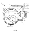
- a washing and drying machine 2 comprises a processing tub 4, two ends of a drying air circulating passage 6 are respectively connected to the processing tub 4, a condensing assembly 8 is located in the drying air circulating passage 6, and the condensing assembly 8 has an air flow passage 10 which is in communication with the drying air circulating passage 6. Therefore, the air flowing from the drying air circulating passage 6 and through the condensing assembly 8 has heat exchange in the air flow passage 10, and the water therein is condensed.
- Spraying means 12 is combined with a condensing assembly 8 and connected to a common water source 13 to spray the water from the common water source 13 to the air flow passage 10 of the condensing assembly 8 in a spraying manner, so as to flush away the thrum adhered to the air flow passage 10.
- the spraying means sprays water into the air flow passage for condensing the water in the drying air flow.
- the spraying means 12 comprises a water charging passage 14, with one end 16 of the water charging passage being connected to a spraying head 18 and the other end 17 being connected to the common water source 13.
- the spraying head 18 is cup-shaped, and a set of spraying holes 20 are radially formed on the spraying head 18.
- the water charging passage 14 is in communication with the air flow passage 10 of the condensing assembly 8 via the spraying holes 20.
- the number of the spraying holes 20 is at least two, to ensure a relatively large spraying range.
- the water charging passage 14 comprises a part 22 substantially parallel to the direction of gravity, the side wall (15) of the part has an opening 24 separating the water charging passage 14 into a first part 26 and a second part 28, which are separated from each other.
- the first part 26 can be partially connected to the second part 28, and the degree of connection shall ensure that water will not flow back through the connecting part. Ideally, the lesser the connection degree, the better the effect.
- the inner diameter of the first part 26 is slightly smaller than that of the second part 28, so as to ensure that the water spraying out of the first part 26 can fall into the second part 28 as much as possible.
- the air flow passage 10 of the processing tub 4 and the condensing assembly 8 has a preset maximum allowable level 3, and the opening 24 is higher than said maximum allowable level 3, as shown in Fig. 1 . In other embodiments, it is only necessary to ensure that the opening 24 is not submerged by the washing water and at least a part of the opening 24 is higher than the maximum allowable level 3.
- the water charging passage 14 has an opening 24, water will overflow from the opening 24 if the water pressure is high and the velocity of the injection water flowing from outside is higher than the spraying velocity of the spraying head 18.
- the opening 24 is in communication with an overflow cavity 30, and the overflow cavity 30 is further in communication with the air flow passage 10 of the condensing assembly 8, so that the overflow can flow into the air flow passage 10.
- the spraying means 12 also has an air passage 32 which is in communication with the atmosphere, and the air passage 32 is in communication with said opening (24) which ensures that the opening (24) is always in communication with the atmosphere, even at the maximum allowable level 3.
Landscapes
- Engineering & Computer Science (AREA)
- Textile Engineering (AREA)
- Detail Structures Of Washing Machines And Dryers (AREA)
- Main Body Construction Of Washing Machines And Laundry Dryers (AREA)
Applications Claiming Priority (1)
| Application Number | Priority Date | Filing Date | Title |
|---|---|---|---|
| CN2008101567907A CN101684605B (zh) | 2008-09-26 | 2008-09-26 | 洗衣干衣机 |
Publications (1)
| Publication Number | Publication Date |
|---|---|
| EP2169101A2 true EP2169101A2 (de) | 2010-03-31 |
Family
ID=41650186
Family Applications (1)
| Application Number | Title | Priority Date | Filing Date |
|---|---|---|---|
| EP09170978A Withdrawn EP2169101A2 (de) | 2008-09-26 | 2009-09-22 | Wasch- und Trockenmaschine |
Country Status (2)
| Country | Link |
|---|---|
| EP (1) | EP2169101A2 (de) |
| CN (1) | CN101684605B (de) |
Families Citing this family (2)
| Publication number | Priority date | Publication date | Assignee | Title |
|---|---|---|---|---|
| ES2617216T3 (es) * | 2011-03-29 | 2017-06-15 | Lg Electronics Inc. | Aparato de tratamiento de ropa que incorpora un dispositivo de limpieza con intercambiador de calor |
| CN103572569B (zh) * | 2012-07-27 | 2017-02-15 | 博西华电器(江苏)有限公司 | 具有供水组件的家用电器 |
Family Cites Families (3)
| Publication number | Priority date | Publication date | Assignee | Title |
|---|---|---|---|---|
| DE4427361A1 (de) * | 1994-08-02 | 1996-02-08 | Bosch Siemens Hausgeraete | Zum Trocknen eingerichtete Waschmaschine |
| KR100446773B1 (ko) * | 2002-04-24 | 2004-09-01 | 엘지전자 주식회사 | 드럼형 건조세탁기의 통기장치 |
| CN100503954C (zh) * | 2004-11-30 | 2009-06-24 | 乐金电子(天津)电器有限公司 | 具备烘干功能的滚筒洗衣机 |
-
2008
- 2008-09-26 CN CN2008101567907A patent/CN101684605B/zh not_active Expired - Fee Related
-
2009
- 2009-09-22 EP EP09170978A patent/EP2169101A2/de not_active Withdrawn
Also Published As
| Publication number | Publication date |
|---|---|
| CN101684605B (zh) | 2012-11-28 |
| CN101684605A (zh) | 2010-03-31 |
Similar Documents
| Publication | Publication Date | Title |
|---|---|---|
| US8377224B2 (en) | Cleaning device for a component loaded with lint in a household appliance, and method for cleaning a component loaded with lint | |
| EP2169107B1 (de) | Trockner mit einer Sprüheinrichtung | |
| IT8934090U1 (it) | Dispositivo di condensazione del vapore per macchine asciugabiancheria o macchine combinate per il lavaggio e l'asciugatura della biancheria | |
| CN101876132B (zh) | 洗衣干衣机 | |
| CN104545755B (zh) | 水槽式清洗机的透气冷凝装置 | |
| CN107641947A (zh) | 热泵换热系统、热泵洗干一体机或干衣机、自动清洗方法 | |
| CN106821265A (zh) | 一种带冷凝干燥功能的呼吸器及使用其的洗碗机 | |
| EP3124681A1 (de) | Wäschebehandlungsvorrichtung | |
| EP2764153B1 (de) | Waschmaschine und wäschetrockner mit einem kondensator | |
| CN104032552A (zh) | 衣物处理装置 | |
| CN103572569B (zh) | 具有供水组件的家用电器 | |
| CN103898727B (zh) | 一种干衣机冷凝水排水结构及干衣机 | |
| CN110072426B (zh) | 用于干燥餐具等的机器、以及用所述机器干燥餐具等的方法 | |
| KR20160149608A (ko) | 건조 장치 및 그 제조 방법 | |
| CN106343935A (zh) | 用水家用电器 | |
| ITMI951532A1 (it) | Un dispositivo per la condensazione dei vapori di sfiato dalla vasca di lavaggio di macchine lavastoviglie e simili | |
| ITMI990664U1 (it) | Camera di condensazione del vapore per macchine lavastoviglie | |
| CN104968853B (zh) | 包括冷凝器的衣物洗涤干燥机 | |
| EP1656877A2 (de) | Geschirrspüler | |
| CN206507910U (zh) | 用水家用电器 | |
| CN101781841B (zh) | 织物烘干设备 | |
| CN101684605B (zh) | 洗衣干衣机 | |
| CN115627622A (zh) | 水路系统及衣物处理设备 | |
| EP3374563B1 (de) | Waschmaschine/trockner mit einem kondensator | |
| CN211571122U (zh) | 排水装置及具有其的洗衣机 |
Legal Events
| Date | Code | Title | Description |
|---|---|---|---|
| PUAI | Public reference made under article 153(3) epc to a published international application that has entered the european phase |
Free format text: ORIGINAL CODE: 0009012 |
|
| AK | Designated contracting states |
Kind code of ref document: A2 Designated state(s): AT BE BG CH CY CZ DE DK EE ES FI FR GB GR HR HU IE IS IT LI LT LU LV MC MK MT NL NO PL PT RO SE SI SK SM TR |
|
| AX | Request for extension of the european patent |
Extension state: AL BA RS |
|
| RAP1 | Party data changed (applicant data changed or rights of an application transferred) |
Owner name: BSH HAUSGERAETE GMBH |
|
| STAA | Information on the status of an ep patent application or granted ep patent |
Free format text: STATUS: THE APPLICATION IS DEEMED TO BE WITHDRAWN |
|
| 18D | Application deemed to be withdrawn |
Effective date: 20150331 |