EP2168905A2 - Flurförderzeug mit Anzeige- und Bedienvorrichtung - Google Patents
Flurförderzeug mit Anzeige- und Bedienvorrichtung Download PDFInfo
- Publication number
- EP2168905A2 EP2168905A2 EP09010944A EP09010944A EP2168905A2 EP 2168905 A2 EP2168905 A2 EP 2168905A2 EP 09010944 A EP09010944 A EP 09010944A EP 09010944 A EP09010944 A EP 09010944A EP 2168905 A2 EP2168905 A2 EP 2168905A2
- Authority
- EP
- European Patent Office
- Prior art keywords
- display
- driver
- operating device
- seat
- industrial truck
- Prior art date
- Legal status (The legal status is an assumption and is not a legal conclusion. Google has not performed a legal analysis and makes no representation as to the accuracy of the status listed.)
- Granted
Links
Images

Classifications
-
- B—PERFORMING OPERATIONS; TRANSPORTING
- B66—HOISTING; LIFTING; HAULING
- B66F—HOISTING, LIFTING, HAULING OR PUSHING, NOT OTHERWISE PROVIDED FOR, e.g. DEVICES WHICH APPLY A LIFTING OR PUSHING FORCE DIRECTLY TO THE SURFACE OF A LOAD
- B66F9/00—Devices for lifting or lowering bulky or heavy goods for loading or unloading purposes
- B66F9/06—Devices for lifting or lowering bulky or heavy goods for loading or unloading purposes movable, with their loads, on wheels or the like, e.g. fork-lift trucks
- B66F9/075—Constructional features or details
- B66F9/20—Means for actuating or controlling masts, platforms, or forks
- B66F9/24—Electrical devices or systems
-
- B—PERFORMING OPERATIONS; TRANSPORTING
- B66—HOISTING; LIFTING; HAULING
- B66F—HOISTING, LIFTING, HAULING OR PUSHING, NOT OTHERWISE PROVIDED FOR, e.g. DEVICES WHICH APPLY A LIFTING OR PUSHING FORCE DIRECTLY TO THE SURFACE OF A LOAD
- B66F9/00—Devices for lifting or lowering bulky or heavy goods for loading or unloading purposes
- B66F9/06—Devices for lifting or lowering bulky or heavy goods for loading or unloading purposes movable, with their loads, on wheels or the like, e.g. fork-lift trucks
- B66F9/075—Constructional features or details
- B66F9/0759—Details of operating station, e.g. seats, levers, operator platforms, cabin suspension
Definitions
- the invention relates to an industrial truck with a display and / or operating device.
- the invention relates to an industrial truck with a display and / or operating device, in which are arranged laterally in front of or next to the driver's seat actuators for a lifting device and / or a traction drive of the truck.
- the input device is ergonomically low in reach.
- the spar is usually made as slim as possible in order to restrict the field of view as little as possible, and therefore only a limited size of the display device is possible.
- the display device is located far laterally and not optimally close to the ordinary line of sight and thus the main field of vision of a driver sitting on the driver's seat and looking forward to the road or the load on a hoist.
- an armrest laterally to the driver's seat as an armrest, at the front end, in longitudinal extension in front of or next to the seat surface of the driver's seat actuating elements for the lift of the truck, but also possibly arranged for the driving control.
- actuators for the hydraulic control of the lifting device are provided.
- the driver's seat in the driver's cab is arranged slightly laterally offset in small forklifts with particularly cramped space conditions to make room for the armrest and the actuators.
- this armrest and the actuators are placed on the right side of the driver's seat.
- a display and operating device is arranged in front of the armrest in the region of a front wall of the truck, the risk of unintentional actuation of the actuating elements on the armrest can be even greater, because then the arm is guided at the same height forward or even forward down. Also, the display device is then easily obscured by the control element and this encompassing hand.
- a display unit for a battery-powered truck is known in which various information can be displayed on the same display unit.
- the display unit has a display, separate display fields and operating elements.
- the present invention has for its object to provide a ergonometric favorable arrangement of the display and control device available, with a safe and diligent operation is possible and does not affect the driver's view.
- the object is achieved in that in an industrial truck with a display and / or operating device, arranged in front of or next to a driver's seat steering device, in particular a steering wheel, and laterally in front of the driver's seat arranged actuators for a lifting device and / or a traction drive of the truck in that the display and / or operating device is arranged in front of the driver's seat in an angle formed between an arm movement axis to the steering device and an arm movement axis to the operating elements.
- the arm which actuates the actuators for the stroke control in particular a working and lifting hydraulics, when the operating device of the display and / or operating device is to be reached, already at the beginning of the movement inwards towards the steering device led away from the actuators. It can not come to an unintentional actuation of the actuators, since the arm is moved away from the actuators. By this position, the display and / or operating device is not obscured by the steering device or the actuator and is clearly visible. Finally, the arm movement to reach the display and control device is relatively short and thereby the fatigue-free and convenient operation of the truck is promoted, since the display and control device is easily accessible.
- the display and / or operating device in front of the driver's seat is arranged so high that it is below the visual axis on the lower edge of a windshield for a driver with average size and average seat height adjustment.
- the driver advantageously has to deviate only minimally downwards with his eyes from his normal viewing direction centrally through the windshield in order to be able to see the display device. This can be done without or with only a very small head movement and therefore carried out without fatigue.
- the arrangement on the underside of the windscreen can also be avoided by the knees of the seated driver, without restricting the field of view in the windshield. In particular, this avoids the driver having to assume an uncomfortable posture with his knees in order to avoid obstruction of the display and / or operating device, such as in a deeper arrangement.
- a display surface of the display and / or operating device is aligned substantially perpendicular to the visual axis to this for a driver with average size and average seat height adjustment.
- an orientation of the display device facing the driver enables an optimal readability of the information displayed on the display device.
- the display and / or operating device can also be oriented only at a small angle to the vertical of the viewing axis.
- the display and / or operating device may be integrated at the lower edge of a windscreen in an upper cover surface of a front wall.
- the display and / or operating device may be placed on the upper cover surface of the front wall.
- the display and / or operating device controls on the side facing the steering device.
- the arm which operates the operating elements for the lifting device is guided even more reliably and quickly away from the actuating elements when being guided to the operating device in such a way that no incorrect operation can occur.
- the display and / or operating device in its upper region on a projecting in the direction of the driver's seat side wall.
- the display and / or operating device is shielded against direct sunlight, whereby the readability and visibility is promoted.
- a mirror of the display device is prevented in a windshield.
- a mirror of the display device is prevented in a windshield.
- the side wall outside dark or black colored also a mirroring of the side wall is prevented in the windshield.
- the display and / or operating device may have an oval-shaped front surface.
- the display and / or operating device and arranged laterally in front of or next to the driver's seat actuating elements are arranged in the direction of travel to the right of the steering device.
- the Fig. 1 schematically shows an inventive truck, here as a forklift, with a display and / or operating device.
- a cab 1 with a driver's seat 2 operating devices, such as a steering wheel 3 are arranged.
- a mast 6 In front of a front axle 5, a mast 6 is positioned with a load fork 7.
- the fork 7 can be raised and tilted by not recognizable here lifting cylinder, which can be controlled by actuators 8, eg hand lever or joystick.
- the Fig. 2 shows schematically from above the area of the driver's cab in Fig. 1 with the roof removed, with the steering wheel 3, the driver's seat 2 and the actuators 8, which are arranged in front of an armrest 9.
- a display and / or operating device 10 is arranged in this formed by the Armierisachsen L and B angle, so that from the driver's seat 2 a free and unobscured visual axis S on the display and / or operating device 10 results.
- the display and / or operating device 10 in an upper cover surface 18 of a front wall 12 of the cab 1 in the Fig. 1 integrated. Between the front wall 12 and the driver's seat 2, a footwell 13 is arranged.
- the Fig. 3 schematically shows the view of the steering wheel 3 and the display and / or operating device 10 and a part of the footwell 13.
- a windshield In front of the steering wheel 3 is not recognizable arranged a windshield and is the mast 6 as a lifting device. Below the windscreen is the front wall 12th
- the driver is on the driver's seat, the display and / or operating device 10 is not covered by his knees, the field of view by the display and / or operating device 10 but not limited.
- the view of the display and / or operating device 10 requires only a low down looking, which can be done without fatigue even with frequent repetition. Also, the load and the area in front of the truck when looking at the display and / or operating device 10 still good in the main field of vision to be able to notice any dangers, since no head twisting and wide deviation of the viewing direction is required.
- the display and / or operating device 10 is arranged in the region of the right Holmes the mast 6, so that also in the field of view in the windshield projecting parts mean no further restriction, since the field of view is already covered there by the mast 6. It is also a targeted arrangement in the field of Holmes such conceivable that a display and / or operating device further projects upwards and has a high narrow shape, which is arranged in the masking area of the spar.
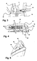
- the Fig. 4 shows the display and / or operating device 10 in detail in a front view.
- a display 17 is arranged as a high-resolution, freely programmable dot matrix display in order to ensure a maximum of displayable information.
- the display and / or operating device 10 is integrated into an upper cover surface 18 of a front wall of the driver's cab 1 of the industrial truck.
- the display and / or operating device 10 has in its upper region a projecting in the direction of the driver's seat side wall 19 as glare protection. This becomes a direct one Sun on the oval surface 16 and the display 17 prevents and improves the readability. Since the side wall 19 is colored black, reflections in the windshield are prevented.
- the Fig. 5 shows the display and / or operating device 10 in detail in side view.
- the display and / or operating device 10 which is integrated into the upper covering surface 18 of the front wall of the driver's cab 1 of the industrial truck with the side wall 19 serving as a glare shield, has, just like the upper covering surface 18, a steeply sloping inclination towards the windshield. This also reduces the risk of reflections.
- dynamic data such as mast tilt, recorded weight, lifting height, steering angle can still be displayed without the driver from the load and the road from the Eyes loses.
- Vehicle position data and goods data can also be displayed on the display 17 via suitable interfaces.
Landscapes
- Engineering & Computer Science (AREA)
- Transportation (AREA)
- Structural Engineering (AREA)
- Civil Engineering (AREA)
- Life Sciences & Earth Sciences (AREA)
- Geology (AREA)
- Mechanical Engineering (AREA)
- Chemical & Material Sciences (AREA)
- Combustion & Propulsion (AREA)
- Instrument Panels (AREA)
- Forklifts And Lifting Vehicles (AREA)
Abstract
Description
- Die Erfindung betrifft ein Flurförderzeug mit einer Anzeige- und/oder Bedienvorrichtung. Insbesondere betrifft die Erfindung ein Flurförderzeug mit einer Anzeige- und/oder Bedienvorrichtung, bei dem seitlich vor oder neben dem Fahrersitz Betätigungselemente für eine Hubvorrichtung und/oder einen Fahrantrieb des Flurförderzeugs angeordnet sind.
- Bekannt ist, in Fahrerkabinen von Flurförderfahrzeugen Anzeige- und Bedienvorrichtungen anzuordnen, die zur Darstellung von unterschiedlichen Fahrzeug- und Fahrzustandsdaten sowie zur Bedienung von Zusatzgeräten benutzt werden. Die Informationsvielfalt, die dem Fahrer dabei zur Verfügung stehen soll, insbesondere in Bezug auf die Fahrzeugzustände, erfordert eine möglichst weitgehende Visualisierung und Darstellung mittels Symbolen auf Bildschirmen oder Displays. Im Bereich der Fahrerkabine eines Flurförderzeugs sind die Platzverhältnisse jedoch relativ beengt.
- Wenn eine Anzeigevorrichtung mit einer Eingabevorrichtung kombiniert wird, ist zusätzlich zu beachten, dass die Eingabevorrichtung ergonometrisch günstig erreichbar ist.
- Bekannt ist, eine Anzeigevorrichtung an einem seitlichen Holm der Kabine und somit am Rand einer Frontscheibe, ungefähr auf Augenhöhe anzubringen.
- Nachteilig ist jedoch, dass der Holm im Regelfall möglichst schlank gestaltet wird, um das Sichtfeld geringstmöglich einzuschränken, und daher nur eine beschränkte Größe der Anzeigevorrichtung möglich ist. Weiter liegt die Anzeigevorrichtung weit seitlich und nicht optimal nahe an der gewöhnlichen Blickrichtung und somit des Hauptsichtfelds eines auf dem Fahrersitz sitzenden und nach vorne auf die Fahrbahn oder die auf einer Hubvorrichtung liegende Last blickenden Fahrers.
- Wird die Anzeigevorrichtung mit einer Eingabevorrichtung kombiniert, so muss beim Bedienen der Arm des Fahrers nach oben seitlich bewegt werden, was zur Ablenkung des Fahrers von der Last und der vor ihm befindlichen Fahrbahn führt.
- Weiter ist bekannt, seitlich zu dem Fahrersitz wie eine Armlehne eine Armauflage anzuordnen, an deren vorderen Ende, in Längserstreckung vor oder neben der Sitzfläche des Fahrersitzes Betätigungselemente für die Hubvorrichtung des Flurförderzeugs, aber auch eventuell für die Fahrsteuerung angeordnet sind. Insbesondere sind Betätigungselemente für die hydraulische Ansteuerung der Hubvorrichtung vorgesehen. Dabei wird bei kleinen Flurförderzeugen mit besonders beengten Platzverhältnissen der Fahrersitz in der Fahrerkabine etwas seitlich versetzt angeordnet, um Platz für die Armauflage und die Betätigungselemente zu schaffen. Für den Regelfall eines Fahrers, der Rechtshänder ist, werden diese Armauflage und die Betätigungselemente auf der rechten Seite des Fahrersitzes angeordnet.
- Dies kann dazu führen, dass beim Bedienen von Eingabevorrichtungen, die an dem Holm angeordnet sind, der Arm über die rechts am Fahrersitz angeordneten Betätigungselemente hinweggeführt wird und es dabei zu einer unabsichtlichen Betätigung der Betätigungselemente kommen kann, da für die Bedienung durch die rechte Hand die Bedienvorrichtung an dem in Fahrtrichtung rechten Holm weiter außen als die Betätigungselemente angeordnet sind.
- Wenn im Bereich einer Vorderwand des Flurförderzeugs vor der Armauflage eine Anzeige- und Bedienvorrichtung angeordnet ist, kann die Gefahr einer unabsichtlichen Betätigung der Betätigungselemente an der Armauflage noch größer sein, da dann der Arm auf gleicher Höhe nach vorne oder sogar nach vorne unten geführt wird. Auch wird die Anzeigevorrichtung dann durch die Bedienelement und die diese umgreifende Hand leicht verdeckt.
- Aus der
DE 102 16 270 A1 ist eine Anzeigeeinheit für ein batteriebetriebenes Flurförderzeug bekannt, bei dem verschiedene Informationen auf derselben Anzeigeeinheit darstellbar sind. - In einer Ausführungsform weist die Anzeigeeinheit ein Display, separate Anzeigefelder und Bedienelemente auf.
- Der vorliegenden Erfindung liegt die Aufgabe zugrunde, eine ergonometrisch günstige Anordnung der Anzeige- und Bedienvorrichtung zur Verfügung zu stellen, mit der eine sichere und ermüdungsfreie Bedienung möglich ist und die die Sicht des Fahrers nicht beeinträchtig.
- Diese Aufgabe wird durch ein Flurförderzeug mit einer Anzeige- und/oder Bedienvorrichtung nach Anspruch 1 gelöst. Vorteilhafte Weiterbildungen werden in den Unteransprüchen angegeben.
- Die Aufgabe wird erfindungsgemäß dadurch gelöst, dass bei einem Flurförderzeug mit einer Anzeige- und/oder Bedienvorrichtung, einer vor oder neben einem Fahrersitz angeordneten Lenkvorrichtung, insbesondere einem Lenkrad, sowie seitlich vor dem Fahrersitz angeordneten Betätigungselementen für eine Hubvorrichtung und/oder einen Fahrantrieb des Flurförderzeugs, die Anzeige- und/oder Bedienvorrichtung vor dem Fahrersitz in einem zwischen einer Armbewegungsachse zu der Lenkvorrichtung und einer Armbewegungsachse zu den Bedienelementen gebildeten Winkel angeordnet ist.
- Vorteilhaft und ergonometrisch günstig wird dann der Arm, der die Betätigungselemente für die Hubsteuerung, insbesondere eine Arbeits- und Hubhydraulik, betätigt, wenn die Bedienvorrichtung der Anzeige- und/oder Bedienvorrichtung erreicht werden soll, schon zu Beginn der Bewegung nach innen zu der Lenkvorrichtung hin von den Betätigungselementen weggeführt. Es kann nicht zu einer unbeabsichtigten Betätigung der Betätigungselemente kommen, da der Arm von den Betätigungselemente wegbewegt wird. Durch diese Position wird die Anzeige- und/oder Bedienvorrichtung auch nicht durch die Lenkvorrichtung oder die Betätigungsvorrichtung verdeckt und ist gut sichtbar. Schließlich ist die Armbewegung zum Erreichen der Anzeige- und Bedienvorrichtung relativ kurz und dadurch wird die ermüdungsfreie und bequeme Bedienung des Flurförderzeugs gefördert, da die Anzeige- und Bedienvorrichtung gut erreichbar ist.
- Zudem ergibt eine derartige Anordnung der Anzeige- und/oder Bedienvorrichtung im Hauptsichtbereich eines auf dem Fahrersitz sitzenden und nach vorne auf die Fahrbahn oder die auf eine auf einer Hubvorrichtung befindliche Last blickende Fahrers eine optimale Ablesbarkeit und Visualisierung der an der Anzeige- und/oder Bedienvorrichtung dargestellten Informationen. Dabei kann der Fahrer in einer ergonometrisch günstigen Arbeitshaltung verbleiben und muss insbesondere nicht seinen Kopf drehen.
- In vorteilhafter Ausführungsform ist die Anzeige- und/oder Bedienvorrichtung vor dem Fahrersitz so hoch angeordnet, dass diese unterhalb der Sichtachse auf die Unterkante einer Frontscheibe für einen Fahrer mit Durchschnittsgröße und mittlerer Sitzhöheneinstellung liegt.
- Dadurch muss der Fahrer vorteilhaft mit seinen Augen von seiner normalen Blickrichtung zentral durch die Frontscheibe nur minimal nach unten abweichen, um die Anzeigevorrichtung sehen zu können. Dies kann ohne oder mit einer nur sehr geringen Kopfbewegung geschehen und daher ermüdungsfrei erfolgen. Durch die Anordnung an der Unterkannte der Frontscheibe kann auch eine Verdeckung durch die Kniee des sitzenden Fahrers vermieden werden, ohne das Sichtfeld in der Frontscheibe einzuschränken. Es wird dadurch insbesondere vermieden, dass der Fahrer mit seinen Knieen eine unbequeme Haltung einnehmen muss, um eine Verdeckung der Anzeige- und/oder Bedienvorrichtung zu vermeiden, wie etwa bei einer tieferen Anordnung.
- In günstiger Ausführungsform ist eine Anzeigefläche der Anzeige- und/oder Bedienvorrichtung im Wesentlichen senkrecht zu der Sichtachse auf diese für einen Fahrer mit Durchschnittsgröße und mittlerer Sitzhöheneinstellung ausgerichtet.
- Eine dem Fahrer zugewandte Ausrichtung der Anzeigevorrichtung ermöglicht eine optimale Ablesbarkeit der an der Anzeigevorrichtung dargestellten Informationen. Dabei kann die Anzeige- und/oder Bedienvorrichtung auch nur unter einem kleinen Winkel zu der Senkrechten der Sichtachse orientiert sein.
- Die Anzeige- und/oder Bedienvorrichtung kann an der Unterkante einer Frontscheibe in eine obere Abdeckfläche einer Vorderwand integriert sein.
- Alternativ kann die Anzeige- und/oder Bedienvorrichtung auf die obere Abdeckfläche der Vorderwand aufgesetzt sein.
- In günstiger Ausführungsform weist die Anzeige- und/oder Bedienvorrichtung Bedienelemente auf der der Lenkvorrichtung zugewandten Seite auf.
- Dadurch wird der Arm, der die Bedienelemente für die Hubvorrichtung bedient, beim Hinführen zu der Bedienvorrichtung noch zuverlässiger und rascher so von den Betätigungselementen weggeführt, dass es zu keinen Fehlbedienungen kommen kann.
- Vorteilhaft weist die Anzeige- und/oder Bedienvorrichtung in ihrem oberen Bereich eine in Richtung des Fahrersitz überstehende Seitenwand auf.
- Durch diese wird die Anzeige- und/oder Bedienvorrichtung gegen direkten Sonneneinfall abgeschirmt, wodurch die Ablesbarkeit und Erkennbarkeit gefördert wird.
- Zum anderen wird ein Spiegeln der Anzeigevorrichtung in einer Frontscheibe verhindert. Insbesondere wenn die Seitenwand außen dunkel oder schwarz gefärbt ist, wird auch ein Spiegeln der Seitenwand in der Frontscheibe verhindert.
- Die Anzeige- und/oder Bedienvorrichtung kann eine ovalförmige Frontfläche aufweisen.
- In günstiger Ausführungsform sind die Anzeige- und/oder Bedienvorrichtung und die seitlich vor oder neben dem Fahrersitz angeordneten Betätigungselemente in Fahrtrichtung rechts von der Lenkvorrichtung angeordnet.
- Dies entspricht der für einen Rechtshänder günstigen Anordnung. Durch eine Anordnung links kann entsprechend eine Anpassung für einen Linkshänder erfolgen.
- Weitere Vorteile und Einzelheiten der Erfindung werden anhand des in den schematischen Figuren dargestellten Ausführungsbeispiels näher erläutert. Hierbei zeigt
- Fig. 1
- schematisch ein Flurförderzeug in der Ausführungsform als Gabelstapler,
- Fig. 2
- schematisch von oben den Bereich des Fahrerarbeitsplatzes in der Fahrerkabine,
- Fig. 3
- schematisch die Sicht auf Lenkrad und Anzeige- und/oder Bedienvorrichtung,
- Fig. 4
- die Anzeige- und/oder Bedienvorrichtung im Detail in einer Frontansicht und
- Fig. 5
- die Anzeige- und/oder Bedienvorrichtung im Detail in einer Seitenansicht.
- Die
Fig. 1 zeigt schematisch ein erfindungsgemäßes Flurförderzeug, hier als Gabelstapler, mit einer Anzeige- und/oder Bedienvorrichtung. In einer Fahrerkabine 1 mit einem Fahrersitz 2 sind Bedieneinrichtungen, wie ein Lenkrad 3 angeordnet. Vor einer Vorderachse 5 ist ein Hubgerüst 6 mit einer Lastgabel 7 positioniert. Die Lastgabel 7 kann durch hier nicht zu erkennende Hubzylinder angehoben und geneigt werden, die durch Betätigungselemente 8, z.B. Handhebel oder Joystick, gesteuert werden können. - Die
Fig. 2 zeigt schematisch von oben den Bereich der Fahrerkabine inFig. 1 bei abgenommenem Dach, mit dem Lenkrad 3, dem Fahrersitz 2 und den Betätigungselementen 8, die vor einer Armauflage 9 angeordnet sind. Dadurch ergibt sich eine Armbewegungsachse B zu den Betätigungselementen 8 und eine Armbewegungsachse L zu der Lenkvorrichtung 3. Eine Anzeige- und/oder Bedienvorrichtung 10 ist in diesem durch die Armbewegungsachsen L und B gebildeten Winkel angeordnet, so dass sich von dem Fahrersitz 2 eine freie und unverdeckte Sichtachse S auf die Anzeige- und/oder Bedienvorrichtung 10 ergibt. Dabei ist die Anzeige- und/oder Bedienvorrichtung 10 in eine obere Abdeckfläche 18 einer Vorderwand 12 der Fahrerkabine 1 in derFig. 1 integriert. Zwischen der Vorderwand 12 und dem Fahrersitz 2 ist ein Fußraum 13 angeordnet. - Die
Fig. 3 zeigt schematisch die Sicht auf das Lenkrad 3 und die Anzeige- und/oder Bedienvorrichtung 10 sowie einen Teil des Fußraums 13. Vor dem Lenkrad 3 ist nicht erkennbar eine Frontscheibe angeordnet und befindet sich das Hubgerüst 6 als Hubvorrichtung. Unterhalb der Frontscheibe befindet sich die Vorderwand 12. - Befindet sich der Fahrer auf dem Fahrersitz, wird die Anzeige- und/oder Bedienvorrichtung 10 nicht von seinen Knien verdeckt, das Sichtfeld durch die Anzeige- und/oder Bedienvorrichtung 10 aber auch nicht eingeschränkt. Der Blick auf die Anzeige- und/oder Bedienvorrichtung 10 erfordert nur ein geringes nach unten Blicken, das auch bei oftmaliger Wiederholung ermüdungsfrei erfolgen kann. Auch ist die Last und der Bereich vor dem Flurförderzeug bei einem Blick auf die Anzeige- und/oder Bedienvorrichtung 10 noch gut im Hauptsichtbereich um eventuelle Gefahren bemerken zu können, da kein Kopfverdrehen und weites Abweichen der Blickrichtung erforderlich ist. Die Anzeige- und/oder Bedienvorrichtung 10 ist auch im Bereich des rechten Holmes das Hubgerüst 6 angeordnet, so dass auch in das Sichtfeld in der Frontscheibe ragende Teile keine weitere Einschränkung bedeuten, da das Sichtfeld dort bereits durch das Hubgerüst 6 verdeckt ist. Es ist auch eine gezielte Anordnung im Bereich des Holmes dergestalt denkbar, dass eine Anzeige- und/oder Bedienvorrichtung weiter nach oben ragt und eine hohe schmale Form aufweist, die im Verdeckungsbereich des Holmes angeordnet ist.
- Die
Fig. 4 zeigt die Anzeige- und/oder Bedienvorrichtung 10 im Detail in einer Frontansicht. Durch die Platzierung der Bedienelemente 15 auf einer ovalen Fläche 16 im linken Bereich, der der Lenkvorrichtung 3 inFig. 3 zugewandten Seite, weicht die Bewegungsrichtung eines die Bedienelemente 15 der Anzeige- und/oder Bedienvorrichtung 10 aufsuchenden Arms des Fahrers maximal von der Armbewegungsachse B zu den Betätigungselementen 8 ab. Eine unabsichtliche Betätigung der Betätigungselemente 8 für die Hydraulik der Hubvorrichtung kann ausgeschlossen werden. Auf der ovalen Fläche 16 ist eine Anzeige 17 als hochauflösende, freiprogrammierbares Dot-Matrix-Display angeordnet, um ein Maximum an darstellbaren Informationen zu gewährleisten. - Rechts neben der Anzeige 17 sind an der Anzeige- und/oder Bedienvorrichtung 10 weitere Anzeigen, z.B. in Form von Pfeilen für die gewählte Fahrtrichtung 20 oder für die Blinker 21, angeordnet.
- Die Anzeige- und/oder Bedienvorrichtung 10 ist in eine obere Abdeckfläche 18 einer Vorderwand der Fahrerkabine 1 des Flurförderzeugs integriert. Die Anzeige- und/oder Bedienvorrichtung 10 weist in ihrem oberen Bereich eine in Richtung des Fahrersitz überstehende Seitenwand 19 als Blendschutz auf. Dadurch wird ein direkter Sonneinfall auf die ovale Fläche 16 und die Anzeige 17 verhindert und die Ablesbarkeit verbessert. Da die Seitenwand 19 schwarz gefärbt ist, werden auch Spiegelungen in der Frontscheibe verhindert.
- Die
Fig. 5 zeigt die Anzeige- und/oder Bedienvorrichtung 10 im Detail in Seitenansicht. Die in die obere Abdeckfläche 18 der Vorderwand der Fahrerkabine 1 des Flurförderzeugs integrierte Anzeige- und/oder Bedienvorrichtung 10 mit der als Blendschutz dienenden Seitenwand 19 weist ebenso wie die obere Abdeckfläche 18 eine stark zu der Frontscheibe abfallende Neigung auf. Dies verringert ebenfalls die Gefahr von Spiegelungen. - Wenn der Fahrer seinen Arm auf der Armablage 9 auflegt und mit der Hand die Betätigungselemente 8 bedient, muss er, um an die Bedienelemente 15 der Anzeige- und/oder Bedienvorrichtung 10 zu gelangen, den Arm vor die Mitte des Körpers aus der Armbewegungsachse B der Betätigungselemente 8 heraus bewegen und sodann nach vorne abwärts senken. Dies ist vorteilhaft mit ergonometrisch günstigen, relativ kurzen Bewegungen möglich. Dabei wird jedoch schon unmittelbar zu Beginn der Bewegung nach dem Loslassen der Betätigungselemente 8 durch die Hand sichergestellt, dass die Betätigungselemente 8 nicht unbeabsichtigt betätigt werden können, da keine Bewegung über die Betätigungselemente 8 hinweg erfolgt, sondern vielmehr die Bewegung nach vorne neben der Armbewegungsachse B zu den Betätigungselementen 8 erfolgt.
- Da sich die Anzeige 17 der Anzeige- und/oder Bedienvorrichtung 10 im Hauptsichtbereich befindet und dem Fahrer direkt zugewandt ist, können weiterhin dynamische Daten wie Mastneigung, aufgenommenes Gewicht, Hubhöhe, Lenkwinkel angezeigt werden, ohne dass der Fahrer die Last und die Fahrbahn aus den Augen verliert. Es können über geeignete Schnittstellen auch Fahrzeugpositionsdaten und Warendaten auf der Anzeige 17 angezeigt werden.
Claims (8)
- Flurförderzeug mit einer Anzeige- und/oder Bedienvorrichtung (10), einer vor einem Fahrersitz (2) angeordneten Lenkvorrichtung (3), insbesondere einem Lenkrad, sowie seitlich vor oder neben dem Fahrersitz (2) angeordneten Betätigungselementen (8) für eine Hubvorrichtung und/oder einen Fahrantrieb des Flurförderzeugs,
dadurch gekennzeichnet,
dass die Anzeige- und/oder Bedienvorrichtung (10) vor dem Fahrersitz (2) in einem zwischen einer Armbewegungsachse (L) zu der Lenkvorrichtung (3)und einer Armbewegungsachse (B)zu den Betätigunselemente (8) gebildeten Winkel angeordnet ist. - Flurförderzeug nach Anspruch 1,
dadurch gekennzeichnet,
dass die Anzeige- und/oder Bedienvorrichtung (10) vor dem Fahrersitz (2) so hoch angeordnet ist, dass diese unterhalb der Sichtachse auf die Unterkante einer Frontscheibe für einen Fahrer mit Durchschnittsgröße und mittlerer Sitzhöheneinstellung liegt. - Flurförderzeug nach Anspruch 1 oder 2,
dadurch gekennzeichnet,
dass eine Anzeigefläche (17) der Anzeige- und/oder Bedienvorrichtung (10) im Wesentlichen senkrecht zu der Sichtachse (S) auf diese für einen Fahrer mit Durchschnittsgröße und mittlerer Sitzhöheneinstellung ausgerichtet ist. - Flurförderzeug nach einem der vorhergehenden Ansprüche,
dadurch gekennzeichnet,
dass die Anzeige- und/oder Bedienvorrichtung (10) an der Unterkante einer Frontscheibe in eine obere Abdeckfläche (18) einer Vorderwand integriert ist. - Flurförderzeug nach einem der vorhergehenden Ansprüche,
dadurch gekennzeichnet,
dass die Anzeige- und/oder Bedienvorrichtung (10) mindestens ein Bedienelemente (15) auf der der Lenkvorrichtung (3) zugewandten Seite aufweist. - Flurförderzeug nach einem der vorhergehenden Ansprüche,
dadurch gekennzeichnet,
dass die Anzeige- und/oder Bedienvorrichtung (10) in ihrem oberen Bereich eine in Richtung des Fahrersitz (2) überstehende Seitenwand (19) aufweist. - Flurförderzeug nach einem der vorhergehenden Ansprüche,
dadurch gekennzeichnet,
dass die Anzeige- und/oder Bedienvorrichtung (10) eine ovalförmige Frontfläche (16) aufweist. - Flurförderzeug nach einem der vorhergehenden Ansprüche,
dadurch gekennzeichnet,
dass die Anzeige- und/oder Bedienvorrichtung (10) und die seitlich vor oder neben dem Fahrersitz (2) angeordneten Bedienelementen (8) in Fahrtrichtung rechts von der Lenkvorrichtung (3) angeordnet sind.
Applications Claiming Priority (1)
| Application Number | Priority Date | Filing Date | Title |
|---|---|---|---|
| DE102008049073A DE102008049073A1 (de) | 2008-09-26 | 2008-09-26 | Flurförderzeug mit Anzeige- und Bedienvorrichtung |
Publications (3)
| Publication Number | Publication Date |
|---|---|
| EP2168905A2 true EP2168905A2 (de) | 2010-03-31 |
| EP2168905A3 EP2168905A3 (de) | 2013-01-16 |
| EP2168905B1 EP2168905B1 (de) | 2015-12-16 |
Family
ID=41435381
Family Applications (1)
| Application Number | Title | Priority Date | Filing Date |
|---|---|---|---|
| EP09010944.8A Revoked EP2168905B1 (de) | 2008-09-26 | 2009-08-26 | Flurförderzeug mit Anzeige- und Bedienvorrichtung |
Country Status (2)
| Country | Link |
|---|---|
| EP (1) | EP2168905B1 (de) |
| DE (1) | DE102008049073A1 (de) |
Cited By (3)
| Publication number | Priority date | Publication date | Assignee | Title |
|---|---|---|---|---|
| DE102011018804A1 (de) | 2011-04-27 | 2012-10-31 | Still Gmbh | Flurförderzeug |
| US20150375782A1 (en) * | 2014-06-30 | 2015-12-31 | Danfoss Power Solutions Aps | Method for controlling steering of a vehicle |
| JP5873906B1 (ja) * | 2014-08-25 | 2016-03-01 | ニチユ三菱フォークリフト株式会社 | リーチ式フォークリフト |
Families Citing this family (1)
| Publication number | Priority date | Publication date | Assignee | Title |
|---|---|---|---|---|
| DE102018101538A1 (de) * | 2018-01-24 | 2019-07-25 | Jungheinrich Aktiengesellschaft | Flurförderzeug |
Family Cites Families (5)
| Publication number | Priority date | Publication date | Assignee | Title |
|---|---|---|---|---|
| DE3106226C2 (de) | 1981-02-19 | 1986-01-09 | Komatsu Forklift K.K., Tokio/Tokyo | Steuerung für Gabelstapler |
| DE10216270A1 (de) | 2002-04-12 | 2003-10-30 | Linde Ag | Anzeigeeinheit für ein Flurförderzeug |
| US6793247B2 (en) * | 2002-07-03 | 2004-09-21 | The Raymond Corporation | Order picker angled steering wheel |
| JP3966789B2 (ja) * | 2002-08-30 | 2007-08-29 | 日本輸送機株式会社 | フォークリフトのステアリング制御装置 |
| DE102005024880A1 (de) | 2005-05-31 | 2006-12-07 | Still Gmbh | Flurförderzeug mit einer grafischen Anzeigevorrichtung |
-
2008
- 2008-09-26 DE DE102008049073A patent/DE102008049073A1/de not_active Withdrawn
-
2009
- 2009-08-26 EP EP09010944.8A patent/EP2168905B1/de not_active Revoked
Cited By (5)
| Publication number | Priority date | Publication date | Assignee | Title |
|---|---|---|---|---|
| DE102011018804A1 (de) | 2011-04-27 | 2012-10-31 | Still Gmbh | Flurförderzeug |
| EP2518009A1 (de) | 2011-04-27 | 2012-10-31 | STILL GmbH | Flurförderzeug |
| US20150375782A1 (en) * | 2014-06-30 | 2015-12-31 | Danfoss Power Solutions Aps | Method for controlling steering of a vehicle |
| US9707998B2 (en) * | 2014-06-30 | 2017-07-18 | Danfoss Power Solutions Aps | Method for controlling steering of a vehicle |
| JP5873906B1 (ja) * | 2014-08-25 | 2016-03-01 | ニチユ三菱フォークリフト株式会社 | リーチ式フォークリフト |
Also Published As
| Publication number | Publication date |
|---|---|
| DE102008049073A1 (de) | 2010-04-01 |
| EP2168905B1 (de) | 2015-12-16 |
| EP2168905A3 (de) | 2013-01-16 |
Similar Documents
| Publication | Publication Date | Title |
|---|---|---|
| EP0950634B1 (de) | Flurförderzeug mit einem Multifunktionshebel | |
| DE69310397T2 (de) | Integrierte Steuer- und Sitzanordnung für Gabelstapler | |
| DE102011055895A1 (de) | Fahrzeugsitz mit seitlichem Stützelement | |
| EP2168905B1 (de) | Flurförderzeug mit Anzeige- und Bedienvorrichtung | |
| DE102011018804A1 (de) | Flurförderzeug | |
| EP2832583A2 (de) | Landwirtschaftliches Fahrzeug | |
| DE2911996A1 (de) | Batteriegetriebener hublader | |
| DE102006022113A1 (de) | Flurförderzeug | |
| DE102004052757A1 (de) | Arbeitsmaschine, insbesondere Flurförderzeug | |
| DE102009019162A1 (de) | Gabelstapler | |
| DE102009019163B4 (de) | Gegengewichts-Gabelstapler mit Fahrerschutzdach | |
| DE102004051256A1 (de) | Anpassungsvorrichtung für eine Fahrzeugplattform | |
| DE69422695T2 (de) | Fahrerkabine für Hebefahrzeuge | |
| DE102016003012B4 (de) | Wählhebelvorrichtung für ein Kraftfahrzeug sowie Kraftfahrzeug mit einer Wählhebelvorrichtung | |
| DE20109218U1 (de) | Kranfahrzeug | |
| EP0949190A2 (de) | Stapler mit Kabine | |
| DE19830373B4 (de) | Lastenhandhabungsfahrzeug | |
| EP1747964B1 (de) | Bedienelementeeinheit mit Minihebeln | |
| EP0960764B1 (de) | Vorrichtung zur Höhenverstellung eines Fahrersitzes | |
| DE102014112896B4 (de) | Flurförderzeug mit einer Anzeige- und Bedienvorrichtung | |
| EP4289665B1 (de) | Fahrersitz-anordnung für ein flurförderzeug | |
| DE19604226A1 (de) | Hubstapler | |
| DE102024107378A1 (de) | Schubmaststapler mit einem Notausschalter | |
| DE102015202103A1 (de) | Fahrzeug, insbesondere Kettenfahrzeug zur Schneepistengestaltung und -pflege | |
| EP4549295A1 (de) | Fahrerkabine für ein landwirtschaftliches arbeitsfahrzeug |
Legal Events
| Date | Code | Title | Description |
|---|---|---|---|
| PUAI | Public reference made under article 153(3) epc to a published international application that has entered the european phase |
Free format text: ORIGINAL CODE: 0009012 |
|
| AK | Designated contracting states |
Kind code of ref document: A2 Designated state(s): AT BE BG CH CY CZ DE DK EE ES FI FR GB GR HR HU IE IS IT LI LT LU LV MC MK MT NL NO PL PT RO SE SI SK SM TR |
|
| AX | Request for extension of the european patent |
Extension state: AL BA RS |
|
| PUAL | Search report despatched |
Free format text: ORIGINAL CODE: 0009013 |
|
| AK | Designated contracting states |
Kind code of ref document: A3 Designated state(s): AT BE BG CH CY CZ DE DK EE ES FI FR GB GR HR HU IE IS IT LI LT LU LV MC MK MT NL NO PL PT RO SE SI SK SM TR |
|
| AX | Request for extension of the european patent |
Extension state: AL BA RS |
|
| RIC1 | Information provided on ipc code assigned before grant |
Ipc: B66F 9/075 20060101ALI20121210BHEP Ipc: B66F 9/24 20060101AFI20121210BHEP |
|
| 17P | Request for examination filed |
Effective date: 20130716 |
|
| RBV | Designated contracting states (corrected) |
Designated state(s): AT BE BG CH CY CZ DE DK EE ES FI FR GB GR HR HU IE IS IT LI LT LU LV MC MK MT NL NO PL PT RO SE SI SK SM TR |
|
| TPAC | Observations filed by third parties |
Free format text: ORIGINAL CODE: EPIDOSNTIPA |
|
| 17Q | First examination report despatched |
Effective date: 20140214 |
|
| GRAP | Despatch of communication of intention to grant a patent |
Free format text: ORIGINAL CODE: EPIDOSNIGR1 |
|
| INTG | Intention to grant announced |
Effective date: 20150626 |
|
| TPAC | Observations filed by third parties |
Free format text: ORIGINAL CODE: EPIDOSNTIPA |
|
| GRAS | Grant fee paid |
Free format text: ORIGINAL CODE: EPIDOSNIGR3 |
|
| GRAA | (expected) grant |
Free format text: ORIGINAL CODE: 0009210 |
|
| AK | Designated contracting states |
Kind code of ref document: B1 Designated state(s): AT BE BG CH CY CZ DE DK EE ES FI FR GB GR HR HU IE IS IT LI LT LU LV MC MK MT NL NO PL PT RO SE SI SK SM TR |
|
| REG | Reference to a national code |
Ref country code: GB Ref legal event code: FG4D Free format text: NOT ENGLISH |
|
| REG | Reference to a national code |
Ref country code: CH Ref legal event code: EP |
|
| REG | Reference to a national code |
Ref country code: IE Ref legal event code: FG4D Free format text: LANGUAGE OF EP DOCUMENT: GERMAN |
|
| REG | Reference to a national code |
Ref country code: AT Ref legal event code: REF Ref document number: 765459 Country of ref document: AT Kind code of ref document: T Effective date: 20160115 |
|
| REG | Reference to a national code |
Ref country code: DE Ref legal event code: R096 Ref document number: 502009011913 Country of ref document: DE |
|
| REG | Reference to a national code |
Ref country code: NL Ref legal event code: MP Effective date: 20151216 |
|
| REG | Reference to a national code |
Ref country code: LT Ref legal event code: MG4D |
|
| PG25 | Lapsed in a contracting state [announced via postgrant information from national office to epo] |
Ref country code: HR Free format text: LAPSE BECAUSE OF FAILURE TO SUBMIT A TRANSLATION OF THE DESCRIPTION OR TO PAY THE FEE WITHIN THE PRESCRIBED TIME-LIMIT Effective date: 20151216 Ref country code: LT Free format text: LAPSE BECAUSE OF FAILURE TO SUBMIT A TRANSLATION OF THE DESCRIPTION OR TO PAY THE FEE WITHIN THE PRESCRIBED TIME-LIMIT Effective date: 20151216 Ref country code: NO Free format text: LAPSE BECAUSE OF FAILURE TO SUBMIT A TRANSLATION OF THE DESCRIPTION OR TO PAY THE FEE WITHIN THE PRESCRIBED TIME-LIMIT Effective date: 20160316 |
|
| PG25 | Lapsed in a contracting state [announced via postgrant information from national office to epo] |
Ref country code: NL Free format text: LAPSE BECAUSE OF FAILURE TO SUBMIT A TRANSLATION OF THE DESCRIPTION OR TO PAY THE FEE WITHIN THE PRESCRIBED TIME-LIMIT Effective date: 20151216 Ref country code: FI Free format text: LAPSE BECAUSE OF FAILURE TO SUBMIT A TRANSLATION OF THE DESCRIPTION OR TO PAY THE FEE WITHIN THE PRESCRIBED TIME-LIMIT Effective date: 20151216 Ref country code: SE Free format text: LAPSE BECAUSE OF FAILURE TO SUBMIT A TRANSLATION OF THE DESCRIPTION OR TO PAY THE FEE WITHIN THE PRESCRIBED TIME-LIMIT Effective date: 20151216 Ref country code: GR Free format text: LAPSE BECAUSE OF FAILURE TO SUBMIT A TRANSLATION OF THE DESCRIPTION OR TO PAY THE FEE WITHIN THE PRESCRIBED TIME-LIMIT Effective date: 20160317 Ref country code: LV Free format text: LAPSE BECAUSE OF FAILURE TO SUBMIT A TRANSLATION OF THE DESCRIPTION OR TO PAY THE FEE WITHIN THE PRESCRIBED TIME-LIMIT Effective date: 20151216 |
|
| PG25 | Lapsed in a contracting state [announced via postgrant information from national office to epo] |
Ref country code: ES Free format text: LAPSE BECAUSE OF FAILURE TO SUBMIT A TRANSLATION OF THE DESCRIPTION OR TO PAY THE FEE WITHIN THE PRESCRIBED TIME-LIMIT Effective date: 20151216 Ref country code: CZ Free format text: LAPSE BECAUSE OF FAILURE TO SUBMIT A TRANSLATION OF THE DESCRIPTION OR TO PAY THE FEE WITHIN THE PRESCRIBED TIME-LIMIT Effective date: 20151216 |
|
| REG | Reference to a national code |
Ref country code: FR Ref legal event code: PLFP Year of fee payment: 8 |
|
| PG25 | Lapsed in a contracting state [announced via postgrant information from national office to epo] |
Ref country code: RO Free format text: LAPSE BECAUSE OF FAILURE TO SUBMIT A TRANSLATION OF THE DESCRIPTION OR TO PAY THE FEE WITHIN THE PRESCRIBED TIME-LIMIT Effective date: 20151216 Ref country code: IS Free format text: LAPSE BECAUSE OF FAILURE TO SUBMIT A TRANSLATION OF THE DESCRIPTION OR TO PAY THE FEE WITHIN THE PRESCRIBED TIME-LIMIT Effective date: 20160416 Ref country code: SK Free format text: LAPSE BECAUSE OF FAILURE TO SUBMIT A TRANSLATION OF THE DESCRIPTION OR TO PAY THE FEE WITHIN THE PRESCRIBED TIME-LIMIT Effective date: 20151216 Ref country code: PT Free format text: LAPSE BECAUSE OF FAILURE TO SUBMIT A TRANSLATION OF THE DESCRIPTION OR TO PAY THE FEE WITHIN THE PRESCRIBED TIME-LIMIT Effective date: 20160418 Ref country code: SM Free format text: LAPSE BECAUSE OF FAILURE TO SUBMIT A TRANSLATION OF THE DESCRIPTION OR TO PAY THE FEE WITHIN THE PRESCRIBED TIME-LIMIT Effective date: 20151216 Ref country code: EE Free format text: LAPSE BECAUSE OF FAILURE TO SUBMIT A TRANSLATION OF THE DESCRIPTION OR TO PAY THE FEE WITHIN THE PRESCRIBED TIME-LIMIT Effective date: 20151216 |
|
| REG | Reference to a national code |
Ref country code: DE Ref legal event code: R026 Ref document number: 502009011913 Country of ref document: DE |
|
| PLBI | Opposition filed |
Free format text: ORIGINAL CODE: 0009260 |
|
| 26 | Opposition filed |
Opponent name: JUNGHEINRICH AKTIENGESELLSCHAFT Effective date: 20160913 |
|
| PLAX | Notice of opposition and request to file observation + time limit sent |
Free format text: ORIGINAL CODE: EPIDOSNOBS2 |
|
| PG25 | Lapsed in a contracting state [announced via postgrant information from national office to epo] |
Ref country code: PL Free format text: LAPSE BECAUSE OF FAILURE TO SUBMIT A TRANSLATION OF THE DESCRIPTION OR TO PAY THE FEE WITHIN THE PRESCRIBED TIME-LIMIT Effective date: 20151216 Ref country code: DK Free format text: LAPSE BECAUSE OF FAILURE TO SUBMIT A TRANSLATION OF THE DESCRIPTION OR TO PAY THE FEE WITHIN THE PRESCRIBED TIME-LIMIT Effective date: 20151216 |
|
| PG25 | Lapsed in a contracting state [announced via postgrant information from national office to epo] |
Ref country code: BE Free format text: LAPSE BECAUSE OF NON-PAYMENT OF DUE FEES Effective date: 20160831 |
|
| REG | Reference to a national code |
Ref country code: DE Ref legal event code: R082 Ref document number: 502009011913 Country of ref document: DE Representative=s name: PATENTSHIP PATENTANWALTSGESELLSCHAFT MBH, DE |
|
| REG | Reference to a national code |
Ref country code: DE Ref legal event code: R082 Ref document number: 502009011913 Country of ref document: DE Representative=s name: PATENTSHIP PATENTANWALTSGESELLSCHAFT MBH, DE |
|
| PG25 | Lapsed in a contracting state [announced via postgrant information from national office to epo] |
Ref country code: SI Free format text: LAPSE BECAUSE OF FAILURE TO SUBMIT A TRANSLATION OF THE DESCRIPTION OR TO PAY THE FEE WITHIN THE PRESCRIBED TIME-LIMIT Effective date: 20151216 |
|
| PLAF | Information modified related to communication of a notice of opposition and request to file observations + time limit |
Free format text: ORIGINAL CODE: EPIDOSCOBS2 |
|
| PG25 | Lapsed in a contracting state [announced via postgrant information from national office to epo] |
Ref country code: MC Free format text: LAPSE BECAUSE OF FAILURE TO SUBMIT A TRANSLATION OF THE DESCRIPTION OR TO PAY THE FEE WITHIN THE PRESCRIBED TIME-LIMIT Effective date: 20151216 |
|
| REG | Reference to a national code |
Ref country code: CH Ref legal event code: PL |
|
| PLBB | Reply of patent proprietor to notice(s) of opposition received |
Free format text: ORIGINAL CODE: EPIDOSNOBS3 |
|
| GBPC | Gb: european patent ceased through non-payment of renewal fee |
Effective date: 20160826 |
|
| PG25 | Lapsed in a contracting state [announced via postgrant information from national office to epo] |
Ref country code: LI Free format text: LAPSE BECAUSE OF NON-PAYMENT OF DUE FEES Effective date: 20160831 Ref country code: CH Free format text: LAPSE BECAUSE OF NON-PAYMENT OF DUE FEES Effective date: 20160831 |
|
| REG | Reference to a national code |
Ref country code: IE Ref legal event code: MM4A |
|
| PG25 | Lapsed in a contracting state [announced via postgrant information from national office to epo] |
Ref country code: IE Free format text: LAPSE BECAUSE OF NON-PAYMENT OF DUE FEES Effective date: 20160826 Ref country code: GB Free format text: LAPSE BECAUSE OF NON-PAYMENT OF DUE FEES Effective date: 20160826 |
|
| REG | Reference to a national code |
Ref country code: FR Ref legal event code: PLFP Year of fee payment: 9 |
|
| PG25 | Lapsed in a contracting state [announced via postgrant information from national office to epo] |
Ref country code: LU Free format text: LAPSE BECAUSE OF NON-PAYMENT OF DUE FEES Effective date: 20160826 |
|
| REG | Reference to a national code |
Ref country code: AT Ref legal event code: MM01 Ref document number: 765459 Country of ref document: AT Kind code of ref document: T Effective date: 20160826 |
|
| PG25 | Lapsed in a contracting state [announced via postgrant information from national office to epo] |
Ref country code: AT Free format text: LAPSE BECAUSE OF NON-PAYMENT OF DUE FEES Effective date: 20160826 |
|
| REG | Reference to a national code |
Ref country code: DE Ref legal event code: R064 Ref document number: 502009011913 Country of ref document: DE Ref country code: DE Ref legal event code: R103 Ref document number: 502009011913 Country of ref document: DE |
|
| PG25 | Lapsed in a contracting state [announced via postgrant information from national office to epo] |
Ref country code: CY Free format text: LAPSE BECAUSE OF FAILURE TO SUBMIT A TRANSLATION OF THE DESCRIPTION OR TO PAY THE FEE WITHIN THE PRESCRIBED TIME-LIMIT Effective date: 20151216 Ref country code: HU Free format text: LAPSE BECAUSE OF FAILURE TO SUBMIT A TRANSLATION OF THE DESCRIPTION OR TO PAY THE FEE WITHIN THE PRESCRIBED TIME-LIMIT; INVALID AB INITIO Effective date: 20090826 |
|
| PG25 | Lapsed in a contracting state [announced via postgrant information from national office to epo] |
Ref country code: MK Free format text: LAPSE BECAUSE OF FAILURE TO SUBMIT A TRANSLATION OF THE DESCRIPTION OR TO PAY THE FEE WITHIN THE PRESCRIBED TIME-LIMIT Effective date: 20151216 Ref country code: MT Free format text: LAPSE BECAUSE OF FAILURE TO SUBMIT A TRANSLATION OF THE DESCRIPTION OR TO PAY THE FEE WITHIN THE PRESCRIBED TIME-LIMIT Effective date: 20151216 Ref country code: TR Free format text: LAPSE BECAUSE OF FAILURE TO SUBMIT A TRANSLATION OF THE DESCRIPTION OR TO PAY THE FEE WITHIN THE PRESCRIBED TIME-LIMIT Effective date: 20151216 |
|
| PG25 | Lapsed in a contracting state [announced via postgrant information from national office to epo] |
Ref country code: BG Free format text: LAPSE BECAUSE OF FAILURE TO SUBMIT A TRANSLATION OF THE DESCRIPTION OR TO PAY THE FEE WITHIN THE PRESCRIBED TIME-LIMIT Effective date: 20151216 |
|
| RDAF | Communication despatched that patent is revoked |
Free format text: ORIGINAL CODE: EPIDOSNREV1 |
|
| STAA | Information on the status of an ep patent application or granted ep patent |
Free format text: STATUS: THE PATENT HAS BEEN GRANTED |
|
| REG | Reference to a national code |
Ref country code: FR Ref legal event code: PLFP Year of fee payment: 10 |
|
| PGFP | Annual fee paid to national office [announced via postgrant information from national office to epo] |
Ref country code: DE Payment date: 20180827 Year of fee payment: 10 Ref country code: FR Payment date: 20180824 Year of fee payment: 10 Ref country code: IT Payment date: 20180823 Year of fee payment: 10 |
|
| RDAG | Patent revoked |
Free format text: ORIGINAL CODE: 0009271 |
|
| STAA | Information on the status of an ep patent application or granted ep patent |
Free format text: STATUS: PATENT REVOKED |
|
| 27W | Patent revoked |
Effective date: 20180530 |
|
| REG | Reference to a national code |
Ref country code: BE Ref legal event code: MM Effective date: 20160831 |
|
| REG | Reference to a national code |
Ref country code: AT Ref legal event code: MA03 Ref document number: 765459 Country of ref document: AT Kind code of ref document: T Effective date: 20180530 |