EP2168778A1 - Halterungselemente für Stachelradvorschub einer Druckerzuführvorrichtung auf ganzer Rollenbreite eines anschlagfreien Druckers - Google Patents
Halterungselemente für Stachelradvorschub einer Druckerzuführvorrichtung auf ganzer Rollenbreite eines anschlagfreien Druckers Download PDFInfo
- Publication number
- EP2168778A1 EP2168778A1 EP09290727A EP09290727A EP2168778A1 EP 2168778 A1 EP2168778 A1 EP 2168778A1 EP 09290727 A EP09290727 A EP 09290727A EP 09290727 A EP09290727 A EP 09290727A EP 2168778 A1 EP2168778 A1 EP 2168778A1
- Authority
- EP
- European Patent Office
- Prior art keywords
- belt
- support
- pins
- printing
- fixing
- Prior art date
- Legal status (The legal status is an assumption and is not a legal conclusion. Google has not performed a legal analysis and makes no representation as to the accuracy of the status listed.)
- Granted
Links
Images

Classifications
-
- B—PERFORMING OPERATIONS; TRANSPORTING
- B41—PRINTING; LINING MACHINES; TYPEWRITERS; STAMPS
- B41J—TYPEWRITERS; SELECTIVE PRINTING MECHANISMS, i.e. MECHANISMS PRINTING OTHERWISE THAN FROM A FORME; CORRECTION OF TYPOGRAPHICAL ERRORS
- B41J15/00—Devices or arrangements of selective printing mechanisms, e.g. ink-jet printers or thermal printers, specially adapted for supporting or handling copy material in continuous form, e.g. webs
- B41J15/18—Multiple web-feeding apparatus
- B41J15/22—Multiple web-feeding apparatus for feeding webs in separate paths during printing
-
- B—PERFORMING OPERATIONS; TRANSPORTING
- B41—PRINTING; LINING MACHINES; TYPEWRITERS; STAMPS
- B41J—TYPEWRITERS; SELECTIVE PRINTING MECHANISMS, i.e. MECHANISMS PRINTING OTHERWISE THAN FROM A FORME; CORRECTION OF TYPOGRAPHICAL ERRORS
- B41J11/00—Devices or arrangements of selective printing mechanisms, e.g. ink-jet printers or thermal printers, for supporting or handling copy material in sheet or web form
- B41J11/26—Pin feeds
- B41J11/30—Pin traction elements other than wheels, e.g. pins on endless bands
-
- B—PERFORMING OPERATIONS; TRANSPORTING
- B65—CONVEYING; PACKING; STORING; HANDLING THIN OR FILAMENTARY MATERIAL
- B65H—HANDLING THIN OR FILAMENTARY MATERIAL, e.g. SHEETS, WEBS, CABLES
- B65H20/00—Advancing webs
- B65H20/16—Advancing webs by web-gripping means, e.g. grippers, clips
Definitions
- the present invention relates to the field of non-impact printing apparatus and more particularly to the field of devices for bringing print media into a printing apparatus.
- each of the pins on the belt is easily and quickly achieved by means of a positioning means which has a first portion which supports a pin and a second portion forming a clamp which attaches to the belt by positioning two elements on the width of the inner face and the outer face of the belt to pinch.
- the structure of these positioning means that for a simultaneous drive of two widths, these means must be oriented successively on either side of the belt by alternately positioning a pin on each side of the belt. Because of the width occupied by each positioning means on the band, the alternative positioning of the pins imposes a step which is half that of the repeat of the eyelets.
- This difference of step then results in a training which is carried out with an alternative insertion of a pin in the half of the eyelets on the margin of a first of the two widths trained then of a second pin in an eyelet of the second width.
- This alternative offset of the pins relative to the trained bands ensures the moving the substrate using only one eyelet out of two on the same band margin, so that for the two width strips moved simultaneously side by side, the eyelets in which a pin is introduced are arranged in staggered rows.
- the present invention aims to overcome one or more disadvantages of the prior art and in particular to provide a solution that allows easy mounting and fixing of pins on the drive means of a printing apparatus of several strips of width while allowing the positioning of pins in each of the eyelets of the margin of the printing substrate to perform its training avoiding its alteration.
- spike support members for insertion into the eyelets of a printing substrate, the support member being adapted to be mounted on the drive belt of a device. supply and drive, characterized in that the pins of the support members are associated in pairs on either side of the belt and intended to be fixed to the belt by positioning the pins facing outward of the belt.
- the support elements for pins are characterized in that the support elements comprise a first element which forms a jumper mounted on the belt and which has a central fixing portion which is positioned on one of the faces of the belt and two side portions of pins support and positioned from and other of the belt, the central portion and the side portions being arranged in parallel planes and the side portions being connected to the central portion by intermediate portions and a second member which completes the attachment of the first support member and has a central fastening portion to the belt which is positioned on the other side of the belt and which interacts with the first support member to grip the belt.
- the support elements for pins are characterized in that the interaction between the first and the second element is carried out by at least one insert disposed on one of the lateral edges of the fixing portion of the second element and intended to be introduced into at least one orifice and / or a notch located in at least one of the lateral or intermediate parts of the first element and / or via a fixing pin which holds the two elements together. secured to each other by riveting, screwing, gluing, welding through the surface of the fixing portion of at least one of them and is arranged to pass through the belt at a suitable orifice.
- the support elements for pins are characterized in that the support elements are associated in pairs, each comprising at least one fixing part intended to be fixed to the belt and a support part intended to be fixed to the belt. supporting a pin pointing towards the outer face of the belt when the support member is attached to the belt, both of these portions being disposed in substantially parallel planes, the attachment portions of the two support members being arranged so that the portion for fastening a first support element is capable of being mounted on the outer face of the belt, and the fixing portion of the second support element is capable of being mounted on the inner face of the belt, the parts of support for respectively supporting a pin are arranged on either side of the belt.
- the support elements for pins are characterized in that the fixing and support parts are interconnected by an intermediate part, the junction of the support part on the intermediate part being identical for each of the support members while the junction of the attachment portion on the intermediate portion of each of the support members differs depending on the positioning of the attachment portion on the outer or inner face of the belt.
- the support elements for pins are characterized in that at least one of the support elements has at least one extension of the attachment portion and / or the intermediate portion, this extension being disposed in a plane substantially perpendicular to the plane of the fixing portion and intended to be positioned against one of the edges of the belt when the fixing portion is fixed on the belt, the end of the extension being in contact with an edge of the portion of fixing or intermediate of the other support element.
- the support elements for pins are characterized in that the interaction between the end of the extension of one of the support elements and the edge in contact with the fixing part or intermediate of the Another support element is made by means of an insert carried by one of the support elements and introduced into a suitable notch carried by the other support element.
- the support elements for pins are characterized in that the central part of the support element which is positioned on the internal face of the belt comprises a relief or an orifice which forms a complementary impression at least one notch disposed on the inner face of the belt.
- Another object of the invention is to provide a device for feeding and driving at least one printing substrate which involves the support elements of the invention.
- a device for feeding and driving at least one printing substrate into a printing apparatus capable of moving at least two printing substrates respectively formed by a band of width and arranged parallel on both sides of the device to be printed simultaneously by positioning at least one margin provided with eyelets arranged, linearly and regularly at a known pitch, the side of the device, the device comprising a displacement means on which is mounted a succession of pins, made by a circular belt held taut between a idler pulley and a drive pulley associated with a motor and / or a control device synchronizing the speed of rotation of the belt with the rotational speed of at least an element of the printing apparatus, so that the belt has at least one face disposed in a plane parallel to the plane of at least one n trained substrate, characterized in that spikes are mounted on either side of the belt a pitch identical to the pitch of the eyelets.
- the device for feeding and driving at least one printing substrate is characterized in that , the belt being provided with notches arranged on its internal face to interact with orifices of at least the driving pulley, the fixing part of the support element which is positioned on the inner face of the belt comprises a hole or a complementary cavity and adapted to the shape of a notch on which the element of support is inserted, to allow optimal mounting of the support member on the notch of the inner face of the belt.
- the device for feeding and driving at least one printing substrate is characterized in that at least one notch positioned on the internal face of the belt is surmounted by the complementary impression of the fixing part of a support element on the inner face of the belt, the orifices of at least one of the pulleys intended to receive notches of the belt are enlarged to be adapted to the volume of a notch surmounted by the fixing portion which has a larger volume than a naked notch.
- the device for feeding and driving at least one printing substrate comprises a means for holding the pin in the eyelet formed by a fixed rail to the frame of the device and disposed along an axis parallel to the axis of the belt so that the pin inserted into the eyelet of the width slides in this rail, blocking the margin of the width that surrounds the eyelet between the rail and the support member of the moving pin driven by the belt.
- Another object of the invention is to provide a printing apparatus which integrates this device and these support elements.
- This objective is achieved by means of a non-impact printing device on at least one printing substrate and capable of simultaneously printing at least two printing substrates respectively formed by a band of width and arranged in parallel by positioning each at least a margin provided with eyelets on the side of the other width, characterized in that the printing apparatus integrates at least one device for feeding and driving at least one printing substrate according to the invention. .
- the non-impact printing apparatus is characterized in that the printing apparatus integrates a plurality of feeder and drive device to allow simultaneous printing of several strips of widths. arranged parallel to each other.
- the non-impact printing apparatus is characterized in that the printing apparatus incorporates a device for reversing the portion of a band of width moved by the delivery device. of the substrate and printed on a first face so that the printing apparatus simultaneously prints a first face and a second face of the same width band, two parts of which are positioned parallel and simultaneously driven by the device for feeding and driving the substrate.
- Another object of the invention is to provide a method of placing the support elements of the delivery device and training of the invention.
- the present invention is intended for all devices for driving the printing substrate (1) of non-impact printing apparatuses which may be both printers and photocopiers and intended for the simultaneous printing of several webs at the same time.
- (1) provided with eyelets (1a) arranged regularly and linearly along each of the margins.
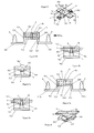
- the feeding and driving device of the invention is formed by a tractor of the printing substrate (1) which ensures the insertion of pins (4) in each of the eyelets (1a) arranged along each of the margins strips of widths (1) to be printed and the formation of the widths (1a) by their margins towards a suitable printing device.
- the printing substrate supply device (1) comprises a belt (3) which forms a circular ribbon stretched between two pulleys (7) mounted on the frame (8) of the device.
- a first of these pulleys (7a) is associated with a motor to drive the belt (3) while the second pulley (7b) is mounted idle to ensure a minimum tension of the belt (3) while allowing a rotation of the belt (3).
- the driving motor of the pulley (7) is associated with a control device which synchronizes the speed of rotation of the belt (3) with the speed of rotation of at least one element of the device. printing, for example a drum, a transfer roller, etc.
- the axis of the belt (3) and its direction of rotation define the axis of the formation of the widths (1) and the direction of movement towards the printing device.
- the belt (3) is positioned between the surfaces occupied by two widths (1) intended to be brought by the device of the invention, so that at least one margin provided with eyelets (1a) of each of the widths (1 ) is arranged along the belt (3).
- the circular ribbon of the belt (3) once stretched between the two pulleys (7), has at least one portion disposed in a plane parallel to that of the strips of widths (1) intended to be driven.
- the pulleys (7) and a portion of the belt (3) are positioned in a trench of the frame (8) arranged along the axis of the belt (3), so that part of the belt (3) allows the positioning of the pins (4) it supports level with the surface of the frame (8) of the device and ensures the sliding strips of widths (1) trained on the surface of the frame (8).
- the pins (4) are fixed in pairs. These pins (4) have a diameter at most equal to that of the eyelets (1a) widths (1), so as to be easily introduced into the eyelets (1a) of each of the widths (1).
- the pairs of pins (4) are fixed in a pitch which is identical to the pitch of the eyelets (1a) in the margins of the strips of widths (1a).
- the fixing of the pins in pairs on the belt (3) is achieved by means of support elements which are arranged on either side of the belt (3) on which they are fixed by positioning the pins (4) facing the belt. outside the belt (3).
- the fixing of the pins (4) in pairs on the belt (3) implements a pair of support elements (51, 52).
- a first of these elements (51) forms a rider mounted on the belt (3).
- This element (51) comprises a central portion (511) for attachment to the belt (3) which is positioned on one of the internal or external faces of the belt (3) and two lateral parts (512a, 512b) which are positioned on either side of the belt (3).
- the central part (511) and the lateral parts (512a, 512b) are preferably arranged in planes parallel to each other, the lateral parts (512a, 512b) being preferably positioned in the same plane on each side of the belt (3) .
- the central (511) and lateral (512a, 512b) portions are positioned on different levels and are interconnected by intermediate portions (513). These intermediate parts (513) extend the central part (511) on each side of the belt (3) in oblique planes or parallel to the plane of the central portion (511) and symmetrically with respect to the plane of symmetry that forms the plane disposed in the axis of the belt (3) and perpendicular to the plane of the belt (3).
- Each intermediate portion (513) forms a leg which is positioned at least against the edge of the belt (3), the two intermediate parts (513) thus enclose the belt (3) being respectively disposed against an edge of the belt (3).
- a second element (52) is positioned on the belt (3) on the face left free by the first element (51). This element has at least one central part (521) which is positioned against the belt (3) and is connected to the first element (51) to attach to the belt (3) which is enclosed by the two support elements (51). , 52).
- Fixing the two elements (51, 52) between them is preferably carried out by a fixing pin (6) which passes through the belt (3) at a particular hole or orifice (3b).
- the tenon (6) joins the two elements (51, 52) together so that these elements enclose the belt (3).
- This fixing element (6) is also capable of passing through the central part (511, 521) of one of the two support elements (51, 52) and can take the form of a screwable, rivetable element, etc.
- Another method of attachment which can be associated with the fastening element (6) which passes through the belt (3), involves one or more inserts (9a3, 9a4) positioned on the edges of the second support member (52). and oriented both sides of the belt (3).
- inserts (9a3, 9a4) are intended to be introduced respectively into at least one orifice or indentation (9b3, 9b4) positioned on the first element (51) at its intermediate (512) or lateral (513) parts.
- the fixing of the pins (4) in pairs on the belt (3) takes place via a pair of support elements (5a, 5b) for pins (4) and for to be mounted on the belt (3) of the feeding and driving device.
- These support members (5a, 5b), mounted in pairs on the belt (3) each comprise at least one attachment portion (5a1, 5b1) for attachment to the belt (3) and a support portion (5a2). , 5b2) for supporting a pin (4).
- the pins (4) are mounted on the belt (3) so as to be oriented towards the outer face of the belt (3).
- the two supporting portions (5a2, 5b2) and fixing portions (5a1, 5b1) being arranged in planes substantially parallel to each other and to the surface of the belt (3) on which the support element (5a, 5b ) has climbed.
- the fixing of the pins (4) on their respective support element (5a, 5b) is achieved by screwing, gluing or welding.
- the pins (4) may also be molded with the portions of the support members (5a, 5b, 51) which position them.
- each pair of support members (5a, 5b) a first one (5a) of the two support members of the pair is arranged so that its attachment portion (5a1) can be mounted on the outer face of the belt (3).
- the second (5b) of the support elements is arranged so that its fixing portion (5b1) can be mounted on the inner face of the belt (3).
- the pin support portions (5a2, 5b2) (4) of these support members (5a, 5b) are positioned, once mounted on the belt (3), on either side of the belt (3).
- the support portions (5a2, 5b2) of the pins (4) are arranged symmetrically on either side of the belt (3) and in the same plane, substantially parallel to the plane of the belt (3).
- each pair of support elements (5a, 5b) one of the elements is positioned on the outer face of the belt (3) and the other element is positioned on the inner face of the belt (3), the support elements (5a, 5b) have a different structure to allow positioning of the support portions (5a2, 5b2) in the same plane.
- This difference in structure involves, on each element of the pair, an intermediate portion (5a3, 5b3) which provides the junction between the support portion (5a2, 5b2) and the fixing portion (5a1, 5b1).
- This intermediate portion (5a3, 5b3) is disposed in a plane substantially perpendicular to the planes of the other two parts.
- the intermediate parts (5a3, 5b3) are arranged in oblique planes symmetrical with respect to the axis of symmetry of the belt (3) and comprising an axis oriented between the support portion (5a2, 5b2 ) and the fixing portion (5a1, 5b1) of each support member (5a, 5b).
- the intermediate portions (5a3, 5b3) are positioned against the edges of the belt (3) while the attachment portions (5a1, 5b1) take the belt (3) sandwiched.
- the support portions (5a2, 5b2) of the support elements (5a, 5b) lie in an inwardly offset plane of the belt (3) with respect to the plane of the part of the belt (3) on which the pair of support elements (5a, 5b) are fixed.
- the support member (5a) mounted on the outer face of the belt (3) comprises an intermediate portion (5a3) which has the attachment portion (5a1) at its outermost end with respect to the belt (3), and the support portion (5a2) at its innermost end with respect to the belt (3). Only a portion of the intermediate portion (5a3) is intended to be disposed against the edge of the belt (3). This portion located on the side of the outermost end and in contact with the fixing portion (5a1).
- the support member (5b) mounted on the inner face of the belt (3) comprises an intermediate portion (5b3) which has the support portion (5b2) at its innermost end relative to the belt (3).
- the fixing portion (5b1) is arranged recessed relative to the outermost end of the intermediate portion (5b3).
- the intermediate portion (5b3) thus has an extension which joins an edge of the fastening portion (5a1) of the second support member (5a) along the edge of the belt (3).
- the withdrawal between the positioning level of the fixing portion (5b1) on the intermediate portion (5b3) and the outer end of the intermediate portion (5b3) corresponds to the thickness of the belt (3) and optionally to the thickness of the attachment portion (5a1) of the support member (5a) mounted on the outer face of the belt (3).
- the fixing of the support elements (5a, 5b) between them on the belt (3) is improved at the respective edges of the elements (5a, 5b) which meet, by the intermediate of at least one insert (9a) carried one of the support elements and intended to be introduced into at least one notch (9b) adapted and carried by the other support member.
- an insert (9a1) is carried by the extension of the intermediate portion (5b3) of the support member (5b) which is positioned on the inner face of the belt (3) .
- This insert (9a1) is housed in a notch (9b1) which is carried by the fixing part (5a1) of the support element (5a) of the support element which is positioned on the outer face of the belt ( 3).
- the end of the fastening portion (5b1) of the support member (5b) which is fixed on the inner face of the belt may have an insert (9a2) which is introduced into a notch (9b2) located in the body of the intermediate part (5a3) of the other fixing element (5a).
- the two support elements on the belt (3) are preferably fixed together on the belt (3), the two elements being fixed by gripping the belt (3) at each of its faces.
- This attachment is achieved by means of a fastening means (6), for example and without limitation, riveting, welding or screwing.
- This fastener passes through the belt (3) at an orifice (3b) located preferentially on the axis of symmetry of the belt (3), the two elements are thus fixed together through the belt (3), the fastening means (6) used may also pass through the fastening portion of at least one of the two support members.
- the fastening element (6) can be mounted on the attachment part of one of the support elements, along an axis perpendicular to the plane of the fixing part and passes through the belt (3) then the fixing part of the other support element.
- the support elements must have a width on the one hand sufficient to allow attachment to the belt (3) and provide support pins (4) and on the other hand minimum for the width of the support element does not prevent the rotation of the belt (3) during the passage of the support elements at the pulleys (7).
- the belt (3) comprises a plurality of notches (3a) disposed on its internal face in a pitch identical to the pitch of the eyelets (1a), or in a step which is a non-zero multiple of the pitch of the eyelets.
- These notches (3a) participate in driving the belt (3) by at least the drive pulley (7a), the notches (3a) being inserted into cavities disposed on the periphery of the pulley (7a). in rotation.
- notches (3a) also allow a regular positioning of the support elements (1) for the positioning of the pairs of pins (4) along the belt (3) in a pitch identical to that of the eyelets of the substrate margin of impression.
- the fixing part of the support element which is positioned on the inner face of the belt (3) comprises an orifice or an impression complementary (524, 5b4) which takes the form of a notch (3a) on which the support member is inserted.
- the support element is thus inserted on the notch (3a).
- the positioning of the attachment portion on the notch (3a) of the belt (3) does not eliminate the interaction of the notch (3a) with the pulleys (7) when the attachment portion (521, 5b1) comprises an orifice in which the notch (3a) is positioned and passes through the support element.
- the attachment portion (521, 5b1) When the attachment portion (521, 5b1) has a complementary indentation (524, 5b4), it matches the notch surface (3a) of the belt (3) and the notch (3a) interacts with the pulleys (7). via the attachment portion (521, 5b1).
- the notch (3a) surmounted by this fixing portion then has a larger volume which requires, at the level of the pulleys (7), a hole larger than to receive a notch (3a) so that the interaction between the notch ( 3a) and the pulleys (7) is optimally realized.
- one notch (3a) on two of the belt (3) is equipped with a fastening element (52, 5b), the other notches (3a) being positioned between the fastening elements (52, 5b). 5b).
- the pulleys (7) then have orifices whose volumes are alternately adapted to interact with notches (3a) and notches (3a) mounted with a fastener (52, 5b).
- the notches (3a) of the belt (3) are arranged on the width of the inner face and the orifice (3b) in the belt (3), which allows the fixing of the support elements (5). ), is centered on the notch (3a) of the belt (3).
- the feed and drive device of the invention rotates the belt (3) on which are fixed a succession of pairs of pins (4) via the drive pulley (7a).
- each pin (4) of the pair arrives at the end of the part of the belt (3) which faces the plane of the strips of width (1) to be driven, each pin (4) of the pair is positioned respectively in an eyelet (1a) of a margin of a band of different width (1), the eyelets (1a) strips (1) being arranged vis-à-vis on both sides of the training device.
- the displacement of the pins (4) driven by the belt (3) in rotation ensures the displacement of the webs (1) along the axis of the belt (3).
- each of the pins (4) of the pair is detached from its eyelet (1a) respective and leaves the training strips of widths (1).
- the training device of the invention comprises an element which ensures the maintenance of the pin (4) in its eyelet (1a).
- This element is formed by a rail (2) fixed to the frame (8) of the device and disposed along an axis parallel to the axis of the belt (3).
- the pin (4) inserted in the eyelet (1a) of the width band (1) slides against or in this rail (2) so as to block the margin of the width band (1) surrounding the eyelet (1a) between the rail (2) and the pinion support member (5) in motion driven by the belt (3).
- the training device of the invention is preferably used in a non-impact printing apparatus capable of simultaneously printing at least two printing substrates respectively formed by a strip of width (1) and arranged parallel by positioning each at the same time. minus a margin provided with eyelets (1a) on the side of the other width (1), the margins of the two widths (1) being arranged on either side of the training device of the invention.
- the printing apparatus integrates a plurality of training devices of the invention arranged parallel to each other and actuated by a common motor and / or a common axis to all the driving pulleys (7a). , to allow simultaneous printing of several strips of widths (1), all arranged parallel to each other.
- the printing apparatus incorporates a device for turning over the portion of a strip of web (1) moved by the drive device of the substrate and printed on a first face to be reintroduced parallel to the part. of the strip (1) whose first face is not yet printed so that the printing apparatus simultaneously prints a first face and a second face of the same strip of width (1), two parts of which are positioned in parallel and simultaneously driven by the training device of the invention.
- a printing apparatus using this system for turning over the printing substrate (1) is illustrated by the document US 6,120,142 A1 and in particular by figure 5 of this document.
Landscapes
- Handling Of Sheets (AREA)
- Photosensitive Polymer And Photoresist Processing (AREA)
- Coloring (AREA)
- Accessory Devices And Overall Control Thereof (AREA)
Applications Claiming Priority (1)
| Application Number | Priority Date | Filing Date | Title |
|---|---|---|---|
| FR0805386A FR2936443B1 (fr) | 2008-09-30 | 2008-09-30 | Elements de support de picots pour dispositif d'amenee de support d'impression a laize d'un appareil d'impression "a la demande" non-impact |
Publications (2)
| Publication Number | Publication Date |
|---|---|
| EP2168778A1 true EP2168778A1 (de) | 2010-03-31 |
| EP2168778B1 EP2168778B1 (de) | 2011-11-16 |
Family
ID=40651380
Family Applications (1)
| Application Number | Title | Priority Date | Filing Date |
|---|---|---|---|
| EP09290727A Not-in-force EP2168778B1 (de) | 2008-09-30 | 2009-09-25 | Halterungselemente, Druckerzuführvorrichtung und berührungsloser Drucker |
Country Status (3)
| Country | Link |
|---|---|
| EP (1) | EP2168778B1 (de) |
| AT (1) | ATE533634T1 (de) |
| FR (1) | FR2936443B1 (de) |
Citations (4)
| Publication number | Priority date | Publication date | Assignee | Title |
|---|---|---|---|---|
| US2047233A (en) * | 1932-07-29 | 1936-07-14 | John Q Sherman | Multisectional platen |
| DE3232875A1 (de) * | 1982-09-02 | 1984-03-08 | Mannesmann AG, 4000 Düsseldorf | Papiertransportvorrichtung fuer drucker, insbesondere fuer matrixdrucker |
| US4771921A (en) * | 1987-05-13 | 1988-09-20 | Norfin International, Inc. | Conversion kit to adapt a single-feed continuous form press to dual-feed operation |
| US6120142A (en) | 1993-12-21 | 2000-09-19 | Nipson S.A. | High-speed printer and the uses of such a printer |
-
2008
- 2008-09-30 FR FR0805386A patent/FR2936443B1/fr not_active Expired - Fee Related
-
2009
- 2009-09-25 EP EP09290727A patent/EP2168778B1/de not_active Not-in-force
- 2009-09-25 AT AT09290727T patent/ATE533634T1/de active
Patent Citations (4)
| Publication number | Priority date | Publication date | Assignee | Title |
|---|---|---|---|---|
| US2047233A (en) * | 1932-07-29 | 1936-07-14 | John Q Sherman | Multisectional platen |
| DE3232875A1 (de) * | 1982-09-02 | 1984-03-08 | Mannesmann AG, 4000 Düsseldorf | Papiertransportvorrichtung fuer drucker, insbesondere fuer matrixdrucker |
| US4771921A (en) * | 1987-05-13 | 1988-09-20 | Norfin International, Inc. | Conversion kit to adapt a single-feed continuous form press to dual-feed operation |
| US6120142A (en) | 1993-12-21 | 2000-09-19 | Nipson S.A. | High-speed printer and the uses of such a printer |
Also Published As
| Publication number | Publication date |
|---|---|
| EP2168778B1 (de) | 2011-11-16 |
| FR2936443B1 (fr) | 2010-10-01 |
| ATE533634T1 (de) | 2011-12-15 |
| FR2936443A1 (fr) | 2010-04-02 |
Similar Documents
| Publication | Publication Date | Title |
|---|---|---|
| FR2601626A1 (fr) | Imprimante, cassette de ruban pour imprimante et procede de montage de cassette | |
| FR2480260A1 (fr) | Procede et machine pour former differentes piles a partir d'une bande sans fin | |
| FR2584056A1 (fr) | Procede et dispositif d'assemblage de feuilles pliees. | |
| EP0740613B1 (de) | Blattförmige unterlage aus papier oder dergleichem zum drucken oder reproduzieren für druck- oder reproduktionszwecke | |
| CH661007A5 (fr) | Imprimante pour l'impression simultanee d'une ligne entiere. | |
| EP0771457B1 (de) | Vorrichtung zur selektiven anzeigung eines bildes aus einem satz solcher bilder | |
| FR2720975A1 (fr) | Dispositif d'accrochage de clichés flexibles sur un cylindre d'impression. | |
| EP2168778B1 (de) | Halterungselemente, Druckerzuführvorrichtung und berührungsloser Drucker | |
| FR2528023A1 (fr) | Procede et dispositif pour la reprise de produits plats se presentant en disposition en ecailles, en particulier pour la reprise de feuilles imprimees | |
| EP3377430A1 (de) | Vakuumtransportverfahren und vakuumkammer für tintenstrahldruckmaschine und tintenstrahldruckmaschine | |
| FR2497127A1 (fr) | Appareil et procede pour decouper des fentes dans des rubans d'ailette d'echangeur de chaleur | |
| EP0764518B1 (de) | Modularer Falzapparat für eine Falt- und Zusammenklebemaschine | |
| EP0267431B1 (de) | Einrichtung zum Stapeln von flachen Gegenständen | |
| EP0255427A1 (de) | Mehrfachvorrichtung zur Behandlung von kartonierten Berechtigungsscheinen, besonders von Fahrkarten mit Magnetspur | |
| FR2558771A1 (fr) | Dispositif de guidage du papier dans une machine offset rotative | |
| EP0197802B1 (de) | Offsetdruckmaschine für Metallfolien | |
| FR3059655B1 (fr) | Distributeur d'adhesif et dispositif de raccordement de gaines comportant un tel distributeur | |
| FR2549026A1 (fr) | Appareil de pliage pour machine a imprimer rotative a bobines | |
| LU87927A1 (fr) | Cartouche pour etiquettes | |
| FR2759477A1 (fr) | Panneau d'affichage a bande sans fin | |
| EP0292931B1 (de) | Führungsvorrichtung für Bahnen | |
| FR2522297A1 (fr) | Appareil pour le marquage d'informations sur un support d'informations | |
| FR2528022A1 (fr) | Procede et dispositif pour la reprise de produits plats qui se presentent en disposition en ecailles, en particulier de feuilles imprimees | |
| FR2826606A1 (fr) | Procede de reunion de sachets, dispositif pour la mise en oeuvre du procede et chaine de sachets ainsi que chaine de sachets empiles | |
| FR2514379A1 (fr) | Dispositif d'insertion de trame sur metier a tisser avec griffes a rubans |
Legal Events
| Date | Code | Title | Description |
|---|---|---|---|
| PUAI | Public reference made under article 153(3) epc to a published international application that has entered the european phase |
Free format text: ORIGINAL CODE: 0009012 |
|
| AK | Designated contracting states |
Kind code of ref document: A1 Designated state(s): AT BE BG CH CY CZ DE DK EE ES FI FR GB GR HR HU IE IS IT LI LT LU LV MC MK MT NL NO PL PT RO SE SI SK SM TR |
|
| AX | Request for extension of the european patent |
Extension state: AL BA RS |
|
| 17P | Request for examination filed |
Effective date: 20100921 |
|
| RTI1 | Title (correction) |
Free format text: NEEDLE SUPPORT ELEMENTS, FEEDING DEVICE OF A PRINTING SUBSTRATE AND IMPACT-FREE PRINTING APPARATUS |
|
| GRAP | Despatch of communication of intention to grant a patent |
Free format text: ORIGINAL CODE: EPIDOSNIGR1 |
|
| GRAS | Grant fee paid |
Free format text: ORIGINAL CODE: EPIDOSNIGR3 |
|
| GRAA | (expected) grant |
Free format text: ORIGINAL CODE: 0009210 |
|
| AK | Designated contracting states |
Kind code of ref document: B1 Designated state(s): AT BE BG CH CY CZ DE DK EE ES FI FR GB GR HR HU IE IS IT LI LT LU LV MC MK MT NL NO PL PT RO SE SI SK SM TR |
|
| REG | Reference to a national code |
Ref country code: GB Ref legal event code: FG4D Free format text: NOT ENGLISH |
|
| REG | Reference to a national code |
Ref country code: CH Ref legal event code: EP |
|
| REG | Reference to a national code |
Ref country code: IE Ref legal event code: FG4D Free format text: LANGUAGE OF EP DOCUMENT: FRENCH |
|
| REG | Reference to a national code |
Ref country code: DE Ref legal event code: R096 Ref document number: 602009003722 Country of ref document: DE Effective date: 20120119 |
|
| REG | Reference to a national code |
Ref country code: NL Ref legal event code: VDEP Effective date: 20111116 |
|
| LTIE | Lt: invalidation of european patent or patent extension |
Effective date: 20111116 |
|
| PG25 | Lapsed in a contracting state [announced via postgrant information from national office to epo] |
Ref country code: IS Free format text: LAPSE BECAUSE OF FAILURE TO SUBMIT A TRANSLATION OF THE DESCRIPTION OR TO PAY THE FEE WITHIN THE PRESCRIBED TIME-LIMIT Effective date: 20120316 Ref country code: NO Free format text: LAPSE BECAUSE OF FAILURE TO SUBMIT A TRANSLATION OF THE DESCRIPTION OR TO PAY THE FEE WITHIN THE PRESCRIBED TIME-LIMIT Effective date: 20120216 Ref country code: LT Free format text: LAPSE BECAUSE OF FAILURE TO SUBMIT A TRANSLATION OF THE DESCRIPTION OR TO PAY THE FEE WITHIN THE PRESCRIBED TIME-LIMIT Effective date: 20111116 |
|
| PG25 | Lapsed in a contracting state [announced via postgrant information from national office to epo] |
Ref country code: GR Free format text: LAPSE BECAUSE OF FAILURE TO SUBMIT A TRANSLATION OF THE DESCRIPTION OR TO PAY THE FEE WITHIN THE PRESCRIBED TIME-LIMIT Effective date: 20120217 Ref country code: PT Free format text: LAPSE BECAUSE OF FAILURE TO SUBMIT A TRANSLATION OF THE DESCRIPTION OR TO PAY THE FEE WITHIN THE PRESCRIBED TIME-LIMIT Effective date: 20120316 Ref country code: SI Free format text: LAPSE BECAUSE OF FAILURE TO SUBMIT A TRANSLATION OF THE DESCRIPTION OR TO PAY THE FEE WITHIN THE PRESCRIBED TIME-LIMIT Effective date: 20111116 Ref country code: LV Free format text: LAPSE BECAUSE OF FAILURE TO SUBMIT A TRANSLATION OF THE DESCRIPTION OR TO PAY THE FEE WITHIN THE PRESCRIBED TIME-LIMIT Effective date: 20111116 Ref country code: PL Free format text: LAPSE BECAUSE OF FAILURE TO SUBMIT A TRANSLATION OF THE DESCRIPTION OR TO PAY THE FEE WITHIN THE PRESCRIBED TIME-LIMIT Effective date: 20111116 Ref country code: SE Free format text: LAPSE BECAUSE OF FAILURE TO SUBMIT A TRANSLATION OF THE DESCRIPTION OR TO PAY THE FEE WITHIN THE PRESCRIBED TIME-LIMIT Effective date: 20111116 Ref country code: NL Free format text: LAPSE BECAUSE OF FAILURE TO SUBMIT A TRANSLATION OF THE DESCRIPTION OR TO PAY THE FEE WITHIN THE PRESCRIBED TIME-LIMIT Effective date: 20111116 Ref country code: HR Free format text: LAPSE BECAUSE OF FAILURE TO SUBMIT A TRANSLATION OF THE DESCRIPTION OR TO PAY THE FEE WITHIN THE PRESCRIBED TIME-LIMIT Effective date: 20111116 |
|
| REG | Reference to a national code |
Ref country code: IE Ref legal event code: FD4D |
|
| PG25 | Lapsed in a contracting state [announced via postgrant information from national office to epo] |
Ref country code: CY Free format text: LAPSE BECAUSE OF FAILURE TO SUBMIT A TRANSLATION OF THE DESCRIPTION OR TO PAY THE FEE WITHIN THE PRESCRIBED TIME-LIMIT Effective date: 20111116 |
|
| PG25 | Lapsed in a contracting state [announced via postgrant information from national office to epo] |
Ref country code: BG Free format text: LAPSE BECAUSE OF FAILURE TO SUBMIT A TRANSLATION OF THE DESCRIPTION OR TO PAY THE FEE WITHIN THE PRESCRIBED TIME-LIMIT Effective date: 20120216 Ref country code: IE Free format text: LAPSE BECAUSE OF FAILURE TO SUBMIT A TRANSLATION OF THE DESCRIPTION OR TO PAY THE FEE WITHIN THE PRESCRIBED TIME-LIMIT Effective date: 20111116 Ref country code: EE Free format text: LAPSE BECAUSE OF FAILURE TO SUBMIT A TRANSLATION OF THE DESCRIPTION OR TO PAY THE FEE WITHIN THE PRESCRIBED TIME-LIMIT Effective date: 20111116 Ref country code: CZ Free format text: LAPSE BECAUSE OF FAILURE TO SUBMIT A TRANSLATION OF THE DESCRIPTION OR TO PAY THE FEE WITHIN THE PRESCRIBED TIME-LIMIT Effective date: 20111116 Ref country code: SK Free format text: LAPSE BECAUSE OF FAILURE TO SUBMIT A TRANSLATION OF THE DESCRIPTION OR TO PAY THE FEE WITHIN THE PRESCRIBED TIME-LIMIT Effective date: 20111116 Ref country code: DK Free format text: LAPSE BECAUSE OF FAILURE TO SUBMIT A TRANSLATION OF THE DESCRIPTION OR TO PAY THE FEE WITHIN THE PRESCRIBED TIME-LIMIT Effective date: 20111116 |
|
| PG25 | Lapsed in a contracting state [announced via postgrant information from national office to epo] |
Ref country code: RO Free format text: LAPSE BECAUSE OF FAILURE TO SUBMIT A TRANSLATION OF THE DESCRIPTION OR TO PAY THE FEE WITHIN THE PRESCRIBED TIME-LIMIT Effective date: 20111116 Ref country code: IT Free format text: LAPSE BECAUSE OF FAILURE TO SUBMIT A TRANSLATION OF THE DESCRIPTION OR TO PAY THE FEE WITHIN THE PRESCRIBED TIME-LIMIT Effective date: 20111116 |
|
| REG | Reference to a national code |
Ref country code: AT Ref legal event code: MK05 Ref document number: 533634 Country of ref document: AT Kind code of ref document: T Effective date: 20111116 |
|
| PLBE | No opposition filed within time limit |
Free format text: ORIGINAL CODE: 0009261 |
|
| STAA | Information on the status of an ep patent application or granted ep patent |
Free format text: STATUS: NO OPPOSITION FILED WITHIN TIME LIMIT |
|
| 26N | No opposition filed |
Effective date: 20120817 |
|
| REG | Reference to a national code |
Ref country code: DE Ref legal event code: R097 Ref document number: 602009003722 Country of ref document: DE Effective date: 20120817 |
|
| PG25 | Lapsed in a contracting state [announced via postgrant information from national office to epo] |
Ref country code: AT Free format text: LAPSE BECAUSE OF FAILURE TO SUBMIT A TRANSLATION OF THE DESCRIPTION OR TO PAY THE FEE WITHIN THE PRESCRIBED TIME-LIMIT Effective date: 20111116 |
|
| BERE | Be: lapsed |
Owner name: NIPSON S.A.S. Effective date: 20120930 |
|
| PG25 | Lapsed in a contracting state [announced via postgrant information from national office to epo] |
Ref country code: MC Free format text: LAPSE BECAUSE OF NON-PAYMENT OF DUE FEES Effective date: 20120930 Ref country code: ES Free format text: LAPSE BECAUSE OF FAILURE TO SUBMIT A TRANSLATION OF THE DESCRIPTION OR TO PAY THE FEE WITHIN THE PRESCRIBED TIME-LIMIT Effective date: 20120227 |
|
| PG25 | Lapsed in a contracting state [announced via postgrant information from national office to epo] |
Ref country code: FI Free format text: LAPSE BECAUSE OF FAILURE TO SUBMIT A TRANSLATION OF THE DESCRIPTION OR TO PAY THE FEE WITHIN THE PRESCRIBED TIME-LIMIT Effective date: 20111116 |
|
| REG | Reference to a national code |
Ref country code: FR Ref legal event code: ST Effective date: 20130531 |
|
| PG25 | Lapsed in a contracting state [announced via postgrant information from national office to epo] |
Ref country code: DE Free format text: LAPSE BECAUSE OF NON-PAYMENT OF DUE FEES Effective date: 20130403 Ref country code: BE Free format text: LAPSE BECAUSE OF NON-PAYMENT OF DUE FEES Effective date: 20120930 |
|
| PG25 | Lapsed in a contracting state [announced via postgrant information from national office to epo] |
Ref country code: FR Free format text: LAPSE BECAUSE OF NON-PAYMENT OF DUE FEES Effective date: 20121001 |
|
| REG | Reference to a national code |
Ref country code: DE Ref legal event code: R119 Ref document number: 602009003722 Country of ref document: DE Effective date: 20130403 |
|
| PG25 | Lapsed in a contracting state [announced via postgrant information from national office to epo] |
Ref country code: MT Free format text: LAPSE BECAUSE OF FAILURE TO SUBMIT A TRANSLATION OF THE DESCRIPTION OR TO PAY THE FEE WITHIN THE PRESCRIBED TIME-LIMIT Effective date: 20111116 |
|
| PG25 | Lapsed in a contracting state [announced via postgrant information from national office to epo] |
Ref country code: TR Free format text: LAPSE BECAUSE OF FAILURE TO SUBMIT A TRANSLATION OF THE DESCRIPTION OR TO PAY THE FEE WITHIN THE PRESCRIBED TIME-LIMIT Effective date: 20111116 |
|
| REG | Reference to a national code |
Ref country code: CH Ref legal event code: PL |
|
| GBPC | Gb: european patent ceased through non-payment of renewal fee |
Effective date: 20130925 |
|
| PG25 | Lapsed in a contracting state [announced via postgrant information from national office to epo] |
Ref country code: SM Free format text: LAPSE BECAUSE OF FAILURE TO SUBMIT A TRANSLATION OF THE DESCRIPTION OR TO PAY THE FEE WITHIN THE PRESCRIBED TIME-LIMIT Effective date: 20111116 Ref country code: LU Free format text: LAPSE BECAUSE OF NON-PAYMENT OF DUE FEES Effective date: 20120925 |
|
| PG25 | Lapsed in a contracting state [announced via postgrant information from national office to epo] |
Ref country code: CH Free format text: LAPSE BECAUSE OF NON-PAYMENT OF DUE FEES Effective date: 20130930 Ref country code: HU Free format text: LAPSE BECAUSE OF FAILURE TO SUBMIT A TRANSLATION OF THE DESCRIPTION OR TO PAY THE FEE WITHIN THE PRESCRIBED TIME-LIMIT Effective date: 20090925 Ref country code: GB Free format text: LAPSE BECAUSE OF NON-PAYMENT OF DUE FEES Effective date: 20130925 Ref country code: LI Free format text: LAPSE BECAUSE OF NON-PAYMENT OF DUE FEES Effective date: 20130930 |
|
| PG25 | Lapsed in a contracting state [announced via postgrant information from national office to epo] |
Ref country code: MK Free format text: LAPSE BECAUSE OF FAILURE TO SUBMIT A TRANSLATION OF THE DESCRIPTION OR TO PAY THE FEE WITHIN THE PRESCRIBED TIME-LIMIT Effective date: 20111116 |