EP2168682B1 - Reaktionsverfahren und Reaktionsvorrichtung - Google Patents
Reaktionsverfahren und Reaktionsvorrichtung Download PDFInfo
- Publication number
- EP2168682B1 EP2168682B1 EP09012267A EP09012267A EP2168682B1 EP 2168682 B1 EP2168682 B1 EP 2168682B1 EP 09012267 A EP09012267 A EP 09012267A EP 09012267 A EP09012267 A EP 09012267A EP 2168682 B1 EP2168682 B1 EP 2168682B1
- Authority
- EP
- European Patent Office
- Prior art keywords
- channel
- liquid
- narrowed section
- specimen liquid
- ch1b
- Prior art date
- Legal status (The legal status is an assumption and is not a legal conclusion. Google has not performed a legal analysis and makes no representation as to the accuracy of the status listed.)
- Not-in-force
Links
- 238000006243 chemical reaction Methods 0.000 title claims abstract description 74
- 238000000034 method Methods 0.000 title claims abstract description 22
- 239000007788 liquid Substances 0.000 claims abstract description 174
- 239000000126 substance Substances 0.000 claims abstract description 51
- 238000005406 washing Methods 0.000 claims abstract description 42
- 238000001179 sorption measurement Methods 0.000 claims abstract description 20
- 239000003463 adsorbent Substances 0.000 claims description 4
- 238000003825 pressing Methods 0.000 claims description 2
- 239000000427 antigen Substances 0.000 description 29
- 102000036639 antigens Human genes 0.000 description 29
- 108091007433 antigens Proteins 0.000 description 29
- 239000010419 fine particle Substances 0.000 description 19
- 238000001514 detection method Methods 0.000 description 14
- 238000012360 testing method Methods 0.000 description 10
- 102000039446 nucleic acids Human genes 0.000 description 7
- 108020004707 nucleic acids Proteins 0.000 description 7
- 150000007523 nucleic acids Chemical class 0.000 description 7
- 239000000523 sample Substances 0.000 description 7
- 230000001276 controlling effect Effects 0.000 description 6
- 238000005516 engineering process Methods 0.000 description 6
- 239000000853 adhesive Substances 0.000 description 5
- 230000001070 adhesive effect Effects 0.000 description 5
- 239000000758 substrate Substances 0.000 description 5
- NIXOWILDQLNWCW-UHFFFAOYSA-N acrylic acid group Chemical group C(C=C)(=O)O NIXOWILDQLNWCW-UHFFFAOYSA-N 0.000 description 4
- 108090000623 proteins and genes Proteins 0.000 description 4
- 239000004793 Polystyrene Substances 0.000 description 3
- 238000013459 approach Methods 0.000 description 3
- 230000000052 comparative effect Effects 0.000 description 3
- 230000000694 effects Effects 0.000 description 3
- 229920002223 polystyrene Polymers 0.000 description 3
- 230000000903 blocking effect Effects 0.000 description 2
- 239000003153 chemical reaction reagent Substances 0.000 description 2
- 230000000875 corresponding effect Effects 0.000 description 2
- 238000010586 diagram Methods 0.000 description 2
- 230000005284 excitation Effects 0.000 description 2
- 238000009396 hybridization Methods 0.000 description 2
- 230000002209 hydrophobic effect Effects 0.000 description 2
- 238000003754 machining Methods 0.000 description 2
- 230000035772 mutation Effects 0.000 description 2
- 239000002773 nucleotide Substances 0.000 description 2
- 125000003729 nucleotide group Chemical group 0.000 description 2
- 102000004169 proteins and genes Human genes 0.000 description 2
- 239000000376 reactant Substances 0.000 description 2
- 102000004190 Enzymes Human genes 0.000 description 1
- 108090000790 Enzymes Proteins 0.000 description 1
- CBENFWSGALASAD-UHFFFAOYSA-N Ozone Chemical compound [O-][O+]=O CBENFWSGALASAD-UHFFFAOYSA-N 0.000 description 1
- 239000008280 blood Substances 0.000 description 1
- 210000004369 blood Anatomy 0.000 description 1
- 238000004891 communication Methods 0.000 description 1
- 230000002596 correlated effect Effects 0.000 description 1
- 238000003745 diagnosis Methods 0.000 description 1
- 201000010099 disease Diseases 0.000 description 1
- 208000037265 diseases, disorders, signs and symptoms Diseases 0.000 description 1
- 239000012153 distilled water Substances 0.000 description 1
- 229940079593 drug Drugs 0.000 description 1
- 239000003814 drug Substances 0.000 description 1
- 230000002708 enhancing effect Effects 0.000 description 1
- 239000012530 fluid Substances 0.000 description 1
- 230000002068 genetic effect Effects 0.000 description 1
- 230000005661 hydrophobic surface Effects 0.000 description 1
- 239000000463 material Substances 0.000 description 1
- 239000002245 particle Substances 0.000 description 1
- 230000000644 propagated effect Effects 0.000 description 1
- 238000011002 quantification Methods 0.000 description 1
- 230000000630 rising effect Effects 0.000 description 1
- 230000035945 sensitivity Effects 0.000 description 1
- 238000004381 surface treatment Methods 0.000 description 1
- 229920003002 synthetic resin Polymers 0.000 description 1
- 239000000057 synthetic resin Substances 0.000 description 1
- 229940126585 therapeutic drug Drugs 0.000 description 1
- 108700026220 vif Genes Proteins 0.000 description 1
- XLYOFNOQVPJJNP-UHFFFAOYSA-N water Chemical compound O XLYOFNOQVPJJNP-UHFFFAOYSA-N 0.000 description 1
Images


Classifications
-
- B—PERFORMING OPERATIONS; TRANSPORTING
- B01—PHYSICAL OR CHEMICAL PROCESSES OR APPARATUS IN GENERAL
- B01L—CHEMICAL OR PHYSICAL LABORATORY APPARATUS FOR GENERAL USE
- B01L3/00—Containers or dishes for laboratory use, e.g. laboratory glassware; Droppers
- B01L3/50—Containers for the purpose of retaining a material to be analysed, e.g. test tubes
- B01L3/502—Containers for the purpose of retaining a material to be analysed, e.g. test tubes with fluid transport, e.g. in multi-compartment structures
- B01L3/5027—Containers for the purpose of retaining a material to be analysed, e.g. test tubes with fluid transport, e.g. in multi-compartment structures by integrated microfluidic structures, i.e. dimensions of channels and chambers are such that surface tension forces are important, e.g. lab-on-a-chip
- B01L3/50273—Containers for the purpose of retaining a material to be analysed, e.g. test tubes with fluid transport, e.g. in multi-compartment structures by integrated microfluidic structures, i.e. dimensions of channels and chambers are such that surface tension forces are important, e.g. lab-on-a-chip characterised by the means or forces applied to move the fluids
-
- B—PERFORMING OPERATIONS; TRANSPORTING
- B01—PHYSICAL OR CHEMICAL PROCESSES OR APPARATUS IN GENERAL
- B01L—CHEMICAL OR PHYSICAL LABORATORY APPARATUS FOR GENERAL USE
- B01L2200/00—Solutions for specific problems relating to chemical or physical laboratory apparatus
- B01L2200/02—Adapting objects or devices to another
- B01L2200/026—Fluid interfacing between devices or objects, e.g. connectors, inlet details
- B01L2200/027—Fluid interfacing between devices or objects, e.g. connectors, inlet details for microfluidic devices
-
- B—PERFORMING OPERATIONS; TRANSPORTING
- B01—PHYSICAL OR CHEMICAL PROCESSES OR APPARATUS IN GENERAL
- B01L—CHEMICAL OR PHYSICAL LABORATORY APPARATUS FOR GENERAL USE
- B01L2200/00—Solutions for specific problems relating to chemical or physical laboratory apparatus
- B01L2200/06—Fluid handling related problems
- B01L2200/0605—Metering of fluids
-
- B—PERFORMING OPERATIONS; TRANSPORTING
- B01—PHYSICAL OR CHEMICAL PROCESSES OR APPARATUS IN GENERAL
- B01L—CHEMICAL OR PHYSICAL LABORATORY APPARATUS FOR GENERAL USE
- B01L2200/00—Solutions for specific problems relating to chemical or physical laboratory apparatus
- B01L2200/06—Fluid handling related problems
- B01L2200/0684—Venting, avoiding backpressure, avoid gas bubbles
-
- B—PERFORMING OPERATIONS; TRANSPORTING
- B01—PHYSICAL OR CHEMICAL PROCESSES OR APPARATUS IN GENERAL
- B01L—CHEMICAL OR PHYSICAL LABORATORY APPARATUS FOR GENERAL USE
- B01L2200/00—Solutions for specific problems relating to chemical or physical laboratory apparatus
- B01L2200/10—Integrating sample preparation and analysis in single entity, e.g. lab-on-a-chip concept
-
- B—PERFORMING OPERATIONS; TRANSPORTING
- B01—PHYSICAL OR CHEMICAL PROCESSES OR APPARATUS IN GENERAL
- B01L—CHEMICAL OR PHYSICAL LABORATORY APPARATUS FOR GENERAL USE
- B01L2200/00—Solutions for specific problems relating to chemical or physical laboratory apparatus
- B01L2200/14—Process control and prevention of errors
- B01L2200/143—Quality control, feedback systems
- B01L2200/146—Employing pressure sensors
-
- B—PERFORMING OPERATIONS; TRANSPORTING
- B01—PHYSICAL OR CHEMICAL PROCESSES OR APPARATUS IN GENERAL
- B01L—CHEMICAL OR PHYSICAL LABORATORY APPARATUS FOR GENERAL USE
- B01L2300/00—Additional constructional details
- B01L2300/06—Auxiliary integrated devices, integrated components
- B01L2300/0627—Sensor or part of a sensor is integrated
- B01L2300/0636—Integrated biosensor, microarrays
-
- B—PERFORMING OPERATIONS; TRANSPORTING
- B01—PHYSICAL OR CHEMICAL PROCESSES OR APPARATUS IN GENERAL
- B01L—CHEMICAL OR PHYSICAL LABORATORY APPARATUS FOR GENERAL USE
- B01L2300/00—Additional constructional details
- B01L2300/08—Geometry, shape and general structure
- B01L2300/0809—Geometry, shape and general structure rectangular shaped
- B01L2300/0816—Cards, e.g. flat sample carriers usually with flow in two horizontal directions
-
- B—PERFORMING OPERATIONS; TRANSPORTING
- B01—PHYSICAL OR CHEMICAL PROCESSES OR APPARATUS IN GENERAL
- B01L—CHEMICAL OR PHYSICAL LABORATORY APPARATUS FOR GENERAL USE
- B01L2300/00—Additional constructional details
- B01L2300/08—Geometry, shape and general structure
- B01L2300/0861—Configuration of multiple channels and/or chambers in a single devices
- B01L2300/0874—Three dimensional network
-
- B—PERFORMING OPERATIONS; TRANSPORTING
- B01—PHYSICAL OR CHEMICAL PROCESSES OR APPARATUS IN GENERAL
- B01L—CHEMICAL OR PHYSICAL LABORATORY APPARATUS FOR GENERAL USE
- B01L2300/00—Additional constructional details
- B01L2300/08—Geometry, shape and general structure
- B01L2300/0887—Laminated structure
-
- B—PERFORMING OPERATIONS; TRANSPORTING
- B01—PHYSICAL OR CHEMICAL PROCESSES OR APPARATUS IN GENERAL
- B01L—CHEMICAL OR PHYSICAL LABORATORY APPARATUS FOR GENERAL USE
- B01L2300/00—Additional constructional details
- B01L2300/16—Surface properties and coatings
- B01L2300/161—Control and use of surface tension forces, e.g. hydrophobic, hydrophilic
- B01L2300/163—Biocompatibility
-
- B—PERFORMING OPERATIONS; TRANSPORTING
- B01—PHYSICAL OR CHEMICAL PROCESSES OR APPARATUS IN GENERAL
- B01L—CHEMICAL OR PHYSICAL LABORATORY APPARATUS FOR GENERAL USE
- B01L2400/00—Moving or stopping fluids
- B01L2400/04—Moving fluids with specific forces or mechanical means
- B01L2400/0403—Moving fluids with specific forces or mechanical means specific forces
- B01L2400/0406—Moving fluids with specific forces or mechanical means specific forces capillary forces
-
- B—PERFORMING OPERATIONS; TRANSPORTING
- B01—PHYSICAL OR CHEMICAL PROCESSES OR APPARATUS IN GENERAL
- B01L—CHEMICAL OR PHYSICAL LABORATORY APPARATUS FOR GENERAL USE
- B01L2400/00—Moving or stopping fluids
- B01L2400/04—Moving fluids with specific forces or mechanical means
- B01L2400/0475—Moving fluids with specific forces or mechanical means specific mechanical means and fluid pressure
- B01L2400/0487—Moving fluids with specific forces or mechanical means specific mechanical means and fluid pressure fluid pressure, pneumatics
- B01L2400/049—Moving fluids with specific forces or mechanical means specific mechanical means and fluid pressure fluid pressure, pneumatics vacuum
-
- Y—GENERAL TAGGING OF NEW TECHNOLOGICAL DEVELOPMENTS; GENERAL TAGGING OF CROSS-SECTIONAL TECHNOLOGIES SPANNING OVER SEVERAL SECTIONS OF THE IPC; TECHNICAL SUBJECTS COVERED BY FORMER USPC CROSS-REFERENCE ART COLLECTIONS [XRACs] AND DIGESTS
- Y10—TECHNICAL SUBJECTS COVERED BY FORMER USPC
- Y10T—TECHNICAL SUBJECTS COVERED BY FORMER US CLASSIFICATION
- Y10T436/00—Chemistry: analytical and immunological testing
- Y10T436/11—Automated chemical analysis
- Y10T436/117497—Automated chemical analysis with a continuously flowing sample or carrier stream
-
- Y—GENERAL TAGGING OF NEW TECHNOLOGICAL DEVELOPMENTS; GENERAL TAGGING OF CROSS-SECTIONAL TECHNOLOGIES SPANNING OVER SEVERAL SECTIONS OF THE IPC; TECHNICAL SUBJECTS COVERED BY FORMER USPC CROSS-REFERENCE ART COLLECTIONS [XRACs] AND DIGESTS
- Y10—TECHNICAL SUBJECTS COVERED BY FORMER USPC
- Y10T—TECHNICAL SUBJECTS COVERED BY FORMER US CLASSIFICATION
- Y10T436/00—Chemistry: analytical and immunological testing
- Y10T436/25—Chemistry: analytical and immunological testing including sample preparation
- Y10T436/25375—Liberation or purification of sample or separation of material from a sample [e.g., filtering, centrifuging, etc.]
- Y10T436/255—Liberation or purification of sample or separation of material from a sample [e.g., filtering, centrifuging, etc.] including use of a solid sorbent, semipermeable membrane, or liquid extraction
-
- Y—GENERAL TAGGING OF NEW TECHNOLOGICAL DEVELOPMENTS; GENERAL TAGGING OF CROSS-SECTIONAL TECHNOLOGIES SPANNING OVER SEVERAL SECTIONS OF THE IPC; TECHNICAL SUBJECTS COVERED BY FORMER USPC CROSS-REFERENCE ART COLLECTIONS [XRACs] AND DIGESTS
- Y10—TECHNICAL SUBJECTS COVERED BY FORMER USPC
- Y10T—TECHNICAL SUBJECTS COVERED BY FORMER US CLASSIFICATION
- Y10T436/00—Chemistry: analytical and immunological testing
- Y10T436/25—Chemistry: analytical and immunological testing including sample preparation
- Y10T436/2575—Volumetric liquid transfer
Definitions
- the present invention relates to a reaction method and a reaction apparatus for conducting an adsorption reaction that adsorbs specifically a subject substance of analysis.
- a base sequence of the patient's gene must be known to utilize this information in the treatment of the particular patient.
- the genetic diagnosis for getting the information about mutation of the endogenous gene or single nucleotide polymorphism (SNP) can be executed by amplifying and detecting a target nucleic acid containing such mutation or single nucleotide polymorphism. Therefore, a simple method capable of amplifying and detecting a target nucleic acid in a sample quickly and precisely is demanded.
- an antigen-antibody reaction or a hybridization of nucleic acid is applied to the subject substance of analysis.
- a labeled substance having a high detecting sensitivity such as an enzyme and supporting the above protein, the nucleic acid, or the like that binds specifically to the subject substance of analysis is bonded previously to the subject substance of analysis. Then, the subject substance of analysis is detected and quantitated by detecting and determining quantitatively this labeled substance.
- the technology to perform the antigen-antibody reaction and the washing operation in a single channel while injecting sequentially plural liquids into the single channel is already known (see International Publication 03/062823 Pamphlet, JP-A-2006-337221 , for example).
- the technology to prevent air bubbles from intervening between the liquids during the process of injecting sequentially plural liquids into a single channel is already known (see JP-A-2007-83191 , for example).
- the hydrophobic channel is provided, the air vent hole and the water-repellant valve are provided to the channel, and the air located between the liquids is exhausted by pressure-feeding the liquid.
- a method of conducting and analyzing a reaction in a microchip channel was disclosed in WO- A-2007/122850 .
- the reaction channel contains an immobilized reactant that reacts with a reagent contained in a liquid.
- the reagent is delivered to the immobilized reactant by moving a gas-liquid interface forward and backward along the reaction channel.
- the "nonspecific adsorption” denotes that a substance is adsorbed onto a molecule that does not essentially interact with the substance.
- the nonspecific adsorption denotes such an event that, in the antigen-antibody reaction in which the antigen acting as the subject substance of analysis should be adsorbed specifically by using the antibody that is fixed to the reaction portion and then such antigen should be detected and quantitated by detecting and quantitatively determining a labeled substance that is bonded to the adsorbed antigen, the labeled substance is solely adsorbed onto the reaction portion.
- the present invention has been made in view of the above circumstances, and it is an object of the present invention to provide a reaction method and a reaction apparatus capable of enhancing a detection/ quantitative determination accuracy of a subject substance of analysis by preventing air bubbles from mixing.
- the feeding of the specimen liquid is stopped after the rear end of the specimen liquid flowing through the second channel flows into the first channel, and then the washing liquid is joined to the rear end of the specimen liquid that stops in the first channel, by flowing the washing liquid, through the third channel that is different from the second channel and is converged to the connection portion of the second channel connected to the first channel. Therefore, no bubble is interposed between the specimen liquid and the washing liquid. As a result, the liquid feeding can be stabilized, and also the nonspecific adsorption in the first channel can be suppressed.
- a capillary force working in the narrowed section whose sectional area is smaller than that of the second channel is larger than that of the second channel. Therefore, when the rear end of the specimen liquid flows into the narrowed section from the second channel, the specimen liquid stops there until an internal pressure of the first channel is reduced to overcome the capillary force in the narrowed section, and an internal pressure in the reaction channel is reduced gradually for this while. As a result, the event that the rear end of the specimen liquid flows into the first channel can be detected based on a change in internal pressure of the first channel, and the feeding of the specimen liquid can be stopped.
- the capillary force of the narrowed section is relatively larger than that of the second channel. Therefore, the event that the rear end of the specimen liquid flows into the first channel can be detected more surely.
- connection portion of the first channel can be filled with the liquid, while preventing that the liquid flows easily into the first channel along the edge. Therefore, the air bubbles can be eliminated more surely.
- the feeding of the specimen liquid is stopped after the rear end of the specimen liquid flowing through the second channel flows into the first channel, and then the washing liquid is joined to the rear end of the specimen liquid that stops in the first channel, by flowing the washing liquid through the third channel that is different from the second channel and is converged to the connection portion of the second channel connected to the first channel. Therefore, no bubble is interposed between the specimen liquid and the washing liquid. As a result, the liquid feeding can be stabilized, and also the nonspecific adsorption in the first channel can be suppressed.
- the capillary force working in the narrowed section whose sectional area is smaller than that of the second channel is larger than that of the second channel. Therefore, when the rear end of the specimen liquid flows into the narrowed section from the second channel, the specimen liquid stops there until an internal pressure of the first channel is reduced to overcome the capillary force in the narrowed section, and an internal pressure in the reaction channel is reduced gradually for this while. As a result, the event that the rear end of the specimen liquid flows into the first channel can be detected based on a change in internal pressure of the first channel, and the feeding of the specimen liquid can be stopped.
- the capillary force of the narrowed section is relatively larger than that of the second channel. Therefore, the event that the rear end of the specimen liquid flows into the first channel can be detected more surely.
- connection portion of the first channel can be filled with the liquid, while preventing that the liquid flows easily into the first channel along the edge. Therefore, the air bubbles can be eliminated more surely.
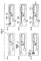
- FIG.1 is a plan view of an example of a microfluid chip used to explain an exemplary embodiment of the present invention
- FIG.2 is a plan view showing the microfluid chip in FIG.1 in a disassembled state
- Fig.3 is a sectional view of the microfluid chip in FIG.1
- FIG. 3 is a sectional view of the microfluid chip in FIG. 1 , which is taken along a III-III line.
- a microfluid chip 1 has a first channel CH1, a second channel CH2, and a third channel CH3 and also a first port PT1, a second port PT2, and a third port PT3 provided to base end portions of these channels CH1 to CH3 respectively.
- a pressure is applied to the ports PT1 to PT3 to control an internal pressure of the channels CH1 to CH3 respectively, and the liquid fed to the microfluid chip 1 is introduced into the ports PT1 to PT3, as occasion demands.
- the first channel CH1 and the second channel CH2 are connected mutually at their tip end portions CH1a, CH2a. Also, the third channel CH3 is converged to the connection portion (tip end portion) CH2a of the second channel CH2 that is connected to the first channel CH1.
- the first channel CH1 provides a section that is continued from the connection portion (tip end portion) CH1a connected to the second channel CH2, and has a narrowed section CH1b whose sectional area a is smaller than a sectional area A of the second channel CH2.
- connection portion CH1a is formed in a bottom surface of the connection portion CH2a of the second channel CH2, and is positioned away from an edge constituting the bottom surface (see FIG.3 ) . Since the opening portion 4a is formed away from the edge, such a situation can be prevented that the liquid flowing through the second channel CH2 propagates along the edge and flows easily into the narrowed section CH1b. Accordingly, first the connection portion CH2a of the second channel CH2 is filled with the liquid, and then the liquid flows into the narrowed section CH1b. Therefore, it can be prevented that air bubbles remain in the connection portion CH2a of the second channel CH2.
- the microfluid chip 1 has a stacked structure consisting of a plurality of layers L1 to L5.
- the first layer L1 is used as a substrate, and a groove 2a is formed in the second layer L2 stacked on the first layer L1, to pass through the layer.
- This groove 2a is used to constitute the narrowed section CH1b of the first channel CH1.
- the second layer L2 is put between the first layer L1 and the third layer L3 on both front and back sides, and the narrowed section CH1b is constructed in the position of the groove 2a.
- a groove 2b constituting the first channel CH1 except the narrowed section CH1b, a groove 2c constituting the second channel CH2, and a groove 2d constituting the third channel CH3 are formed in the fourth layer L4 being stacked on the third layer L3 to pass through the layer respectively.
- the fourth layer L4 is put between the third layer L3 and the fifth layer L5 on both front and back sides, and thus the first channel CH1 except the narrowed section CH1b, the second channel CH2, the third channel CH3 are constructed in the positions of the grooves 2b to 2d respectively.
- port holes 3b to 3d are formed in the fourth layer L4 at base end portions of the grooves 2b to 2d respectively to pass through the layer.
- the through holes 4a, 4b are formed in the third layer L3 interposed between the second layer L2 and the fourth layer L4 to pass through the layer respectively.
- a tip end portion of the groove 2c in the fourth layer L4 overlaps vertically with one end portion of the groove 2a in the second layer L2 (corresponding to the connection portion CH1a of the first channel CH1), and the through hole 4a is arranged between them.
- a tip end portion of the groove 2b in the fourth layer L4 overlaps vertically with the other end portion of the groove 2a in the second layer L2, and the through hole 4b is arranged between them.
- the through hole 4a constitutes an opening of the connection portion CH1a of the first channel CH1 connected to the second channel CH2.
- the through hole 4b connects the narrowed section CH1b and the first channel CH1 except this section.
- port holes 5b to 5d are formed to pass through the layer respectively.
- the port holes 5b to 5d overlap with the port holes 3b to 3d in the fourth layer L4 to constitute the ports PT1 to PT3 respectively, and provide the connection to respective ports PT1 PT3 from the outside.
- the sectional area a of the narrowed section CH1b of the first channel CH1 is set smaller than the sectional area A of the second channel CH2, and these sectional areas are changed according to thicknesses of respective layers.
- a width of the channel is set constant at 2 mm
- a thickness of the fourth layer L4 in which the groove 2c used to constitute the second channel CH2 is formed is set to 0.5 to 3 mm
- a thickness of the second layer L2 in which the groove 2a used to constitute the narrowed section CH1b is set to 0.01 to 0.2 mm.
- the width of the narrowed section CH1b may be set smaller than the width of the second channel CH2, and thus the sectional area a of the narrowed section CH1b may be set smaller than the sectional area A of the second channel CH2.
- the sectional area a of the narrowed section CH1b should be set to 2/5 to 1/300 of the sectional area A of the second channel CH2.
- the above layers L1 to L5 can be formed of a plate manufactured by a synthetic resin such as polystyrene, acrylic, or the like, for example. These layers are joined mutually by interposing adequately the adhesive material such as an adhesive double-coated sheet, or the like between the layers.
- the second layer L2, or the like has a relatively small thickness so as to constitute the narrowed section CH1b of the first channel CH1, such layer itself may be formed of the adhesive double-coated sheet.
- the grooves, the port holes, and the communication holes in respective layers are formed by the laser beam machining, for example.
- a transparent window portion 6a is provided in a portion, which overlaps at least with the groove 2a in the second layer L2, in the third layer L3.
- window holes 6b, 6c are formed in portions, which overlaps similarly with the groove 2a in the second layer L2, in the fourth layer L4 and the fifth layer L5.
- a detecting portion 6 is constructed by the window holes 6b, 6c and the window portion 6a in a state that the layers L1 to L5 are stacked sequentially.
- the narrowed section CH1b of the first channel CH1 can be viewed from the outside through this detecting portion 6.
- FIG.4 is a block diagram showing a schematic configuration of a reaction apparatus containing the microfluid chip.
- the specimen liquid containing the antigen as the subject substance of analysis is fed to the microfluid chip, and then such antigen is detected and quantitated by performing the antigen-antibody reaction in the channel of the microfluid chip.
- the specimen liquid (first liquid) containing the antigen is fed to the second port PT2 of the microfluid chip.
- the washing liquid (second liquid) is fed to the third port PT3.
- the specimen liquid fed to the second port PT2 flows through the second channel CH2, and also the washing liquid fed to the third port PT3 flows through the third channel CH3. Then, these liquids are fed sequentially to the first channel CH1.
- a pretreatment portion CH2b to which a fluorescent fine particle serving as a labeled substance that is supporting the antibody to be bonded to the antigen is fixed, is provided to an intermediate portion of the second channel CH2.
- the specimen liquid passes through the pretreatment portion CH2b, adhesion of the fluorescent fine particle to the pretreatment portion CH2b is released and then the fluorescent fine particle is bonded to the antigen contained in the specimen liquid.
- the specimen liquid may be fed to the second port PT2 in a state that the fluorescent fine particle is bonded in advance to the antigen contained in the specimen liquid.
- the antibody acting as a probe which specifically adsorbs the antigen contained in the specimen liquid, is fixed to the narrowed section CH1b of the first channel CH1 to which the specimen liquid and the washing liquid are fed sequentially.
- the narrowed section CH1b of the first channel CH1 serves as the reaction portion that performs the antigen-antibody reaction.
- the hydrophilicity is given at least to the surface of the narrowed section CH1b as the reaction portion by applying the appropriate surface treatment.
- a reaction apparatus 11 is equipped with the microfluid chip 1, electromagnetic valves SV1 to SV4, a pump 12 that employs an air as a working fluid, a pressure sensor (pressure measuring unit) 13, a liquid position detecting unit 14, a fluorescence detecting unit 15, and a controlling unit 16.
- the first port PT1 and the second port PT2 are connected in parallel to the pump 12 via port pads (not shown) and pipings respectively.
- the electromagnetic valves SV1 to SV3 are interposed in the piping that connects the pump 12 and the second port PT2.
- the third port PT3 is connected to the electromagnetic valve SV4 via the port pad (not shown) and the piping.
- the pressure sensor 13 is provided between the pump 12 and the first port PT1, and measures a pressure that works on the first port PT1, i.e., an internal pressure of the first channel CH1.
- the liquid position detecting unit 14 detects that a front end of the specimen liquid or the washing liquid arrives at an appropriate position in the channels CH1 to CH3.
- a detecting method such a method can be illustrated that a light is irradiated onto a detecting position to detect a reflected light and then the presence or absence of the liquid is decided based upon a change in a quantity of light of the reflected light, which is caused by a change of a refractive index between the air and the liquid.
- a first detection position PH1 is provided to the position that is located on the slightly downstream side from the narrowed section CH1b of the first channel CH1 to the first port PT1.
- a second detection position PH2 is provided to the position of the third channel CH3 prior to a converging portion to the second channel CH2.
- a third detection position PH3 is provided to the position of the first channel CH1 prior to the first port PT1.
- the fluorescence detecting unit 15 irradiates an excitation light of a particular wavelength onto the narrowed section CH1b of the first channel CH1 as the reaction portion through the detecting portion 6 of the microfluid chip 1.
- the fluorescent fine particle which is bonded to the antigen being adsorbed by the antigen-antibody reaction, absorbs the excitation light in the narrowed section CH1b and emits the fluorescence.
- the fluorescence detecting unit 15 detects the antigen by detecting this fluorescence, and quantitates the antigen based on a fluorescence intensity.
- the controlling unit 16 has CPU, ROM that stores a test sequence, and the like.
- the controlling unit 16 receives a measured signal being sent out from the pressure sensor 13 and a detected signal being sent out from the liquid position detecting unit 14, and drives the pump 12 and the electromagnetic valves SV1 to SV4 at appropriate timings indicated based upon these signals such that a pressure is applied to the ports PT1 to PT3, a pressure in the ports PT1 to PT3 is reduced, the ports PT1 to PT3 are opened to the atmosphere, or the ports PT1 to PT3 are closed. Accordingly, the specimen liquid and the washing liquid can be carried freely through the channels CH1 to CH3.
- FIG.5 to FIG.7 are plan views showing states of the microfluid chip in respective steps of the test sequence
- FIG.8 is a time chart showing control timings of the test sequence and states of respective elements of the reaction apparatus along with a time base. Explanation will be made hereunder, while correlating control timings V1-1 to V1-7 in FIG.8 with respective steps S1-1 to S1-15 in FIG.5 to FIG.7 .
- the microfluid chip 1 is prepared (S1-1). Then, the washing liquid is fed to the third port PT3 of the microfluid chip 1 (S1-2). Then, the specimen liquid is fed to the second port PT2 (S1-3).
- the microfluid chip 1 is set to the reaction apparatus 11, and the port pad is pushed against the ports PT1 to PT3 respectively. At this time, respective port pads are opened to the atmosphere, and the specimen liquid and the washing liquid are never moved by pushing the pad.
- the first detection position PH1 When a front end of the specimen liquid arrives at the first detection position PH1 and the liquid position detecting unit 14 turns ON the first detection position PH1 (S1- V1-2), the first port PT1 is opened to the atmosphere and the specimen liquid stops in that position. According to this operation, the specimen liquid can be stopped in a predetermined position with good accuracy. At this time, the first detection position PH1 is set such that a rear end of the specimen liquid is located in the second channel CH2.
- a predetermined time e.g., 0.5 second
- a pressure of the first port PT1 is reduced again, and the specimen liquid flows to the first channel CH1 at a low speed (e.g., 8 ⁇ L/min).
- the antigen-antibody reaction is executed in the narrowed section CH1b as the reaction portion for a predetermined time (e.g., 5 minute) (S1-9).
- the specimen liquid stops automatically S1-10 This is because the sectional area a of the narrowed section CH1b of the first channel CH1 is set smaller than the sectional area A of the second channel CH2 and thus a capillary force working in the narrowed section CH1b becomes larger than a carrying pressure.
- the pump 12 continues to suck without interruptions, and a pressure in the first channel CH1 is reduced gradually. But the specimen liquid still stops until the carrying pressure becomes larger than the capillary force working in the narrowed section CH1b.
- the sectional area a of the narrowed section CH1b of the first channel CH1 should be set to 2/5 to 1/300 of the sectional area A of the second channel CH2. According to this, the capillary force of the narrowed section CH1b is sufficiently large in contrast to that of the second channel CH2, and thus an event that the rear end of the specimen liquid flows into the narrowed section CH1b can be detected more surely.
- a front end of the washing liquid arrives at the second detection position PH2 while the specimen liquid stops in the first channel CH1, the liquid position detecting unit 14 turns ON the second detection position PH2 (S1-12, V1-5). After a predetermined time (e.g., 3 second) has lapsed from this state (V1-6), the washing liquid arrives at the connection portion CH2a of the second channel CH2 to which the third channel CH3 is converged. Since the second channel CH2 is connected to the first channel CH1 at the connection portion CH2a, the washing liquid is joined to the rear end of the specimen liquid without intervention of the air bubbles (S1-13).
- a predetermined time e.g. 3 second
- the second port PT2 is tightly closed, and only a pressure in the first port PT1 is reduced.
- the washing liquid flows to the narrowed section CH1b at a low speed (e.g., 8 ⁇ L/min) subsequently to the specimen liquid without intervention of the air bubbles, and the narrowed section CH1b as the reaction portion is washed (S1-14) . Accordingly, the unreacted antigen and the fluorescent fine particle are exhausted from the narrowed section CH1b.
- FIGS.9A to 9C an antigen-antibody reaction in the reaction portion is schematically shown.
- the specimen liquid containing antigens (subject substances of analysis) Ag, to which a fluorescent fine particle (labeled substance) Id is bonded respectively flows through the narrowed section CH1b of the first channel CH1 as the reaction portion, these antigens Ag are adsorbed specifically by the antibodies (probes) Ig that are fixed in the narrowed section CH1b.
- a part of antigens Ag' may not be adsorbed by the antibodies Ig fixed in the narrowed section CH1b and may be scattered in the specimen liquid.
- a fluorescent fine particle Id' that is not bonded to the antigen Ag and exists solely is contained in the specimen liquid.
- the antigens Ag' which are not adsorbed by the antibody Ig and are scattered in the specimen liquid
- the fluorescent fine particle Id which exists solely in the specimen liquid
- the fluorescent fine particle Id that exists solely in the specimen liquid is adsorbed nonspecifically by the antibody Ig in some cases, and fluorescent fine particles Id' being adsorbed nonspecifically still remain in the narrowed section CH1b even after the washing is applied.
- the fluorescent fine particles that are present in the narrowed section CH1b of the first channel CH1 as the reaction portion are detected and quantitated by the fluorescence detecting unit 15, and then the antigens are detected and quantitated based on that detection and quantification. Since the washing liquid flows through the narrowed section CH1b as the reaction portion subsequently to the specimen liquid without intervention of air bubbles, such an event can be suppressed that the fluorescent fine particles that are not bonded to the antigens and exist solely in the specimen liquid are adsorbed nonspecifically in the narrowed section CH1b as the reaction portion. Accordingly, accuracy in detecting and quantitating the antigen can be improved.
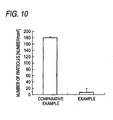
- the labeled substances that exist in the reaction portion after the test sequence is applied were detected and quantitated by using the microfluid chip constructed shown in FIG.1 to FIG.3 .
- the microfluid chip was constructed by stacking sequentially the first layer (100x30x1 mm) formed of the polystyrene substrate, the second layer (100x30x0.05 mm) formed of the adhesive double-coated sheet, the third layer (100x30x0.2 mm) formed of the acrylic substrate, the fourth layer (100x30x0.7 mm) formed of the acrylic substrate onto both surface of which the adhesive double-coated sheet is pasted, and the fifth layer (100x30x0.2 mm) formed of the acrylic substrate.
- the grooves acting as the first to third channels respectively and the port holes acting as the first to third ports respectively were formed in respective layers by the laser beam machining.
- the narrowed section of the first channel was formed to have a width of 2 mm and a depth of 0.05 mm, and served as the reaction portion.
- the second channel connected to the first channel was formed to have a width of 2 mm and a depth of 0.7 mm.
- the hCG antigen was used as the subject substance of analysis, and the anti-hCG antibody was used as the probe fixed to the reaction portion.
- the specimen liquid the liquid containing the fluorescent fine particles (Yellow Green, ⁇ 500 nm), which are supporting the anti-hCG antibody and are formed of polystyrene, as the labeled substance was employed.
- the hCG antigen was not contained in this specimen liquid, and therefore the fluorescent fine particles that exist in the reaction portion of the microfluid chip corresponded to the particles that were adsorbed nonspecifically.
- the PBS-T solution was employed as the washing liquid.
- the present invention is not limited to this situation.
- the present invention can be applied to a situation that nucleic acid is used as the subject substance of analysis and such nucleic acid is adsorbed specifically by using the hybridization and is detected and quantitated.
Landscapes
- Chemical & Material Sciences (AREA)
- Health & Medical Sciences (AREA)
- Dispersion Chemistry (AREA)
- Analytical Chemistry (AREA)
- General Health & Medical Sciences (AREA)
- Hematology (AREA)
- Clinical Laboratory Science (AREA)
- Chemical Kinetics & Catalysis (AREA)
- Automatic Analysis And Handling Materials Therefor (AREA)
Claims (6)
- Verfahren zur Durchführung einer Adsorptionsreaktion, das die folgenden aufeinanderfolgenden Schritte umfasst:Durchfließen einer Probenflüssigkeit, die eine Testsubstanz zur Analyse und eine markierte Substanz enthält, die zur Bindung an die Testsubstanz zur Analyse in der Lage ist, durch einen zweiten Kanal (CH2) in einem ersten Kanal (CH1), die miteinander durch eine Verbindung (CH1a/CH2a) verbunden sind, wobei der erste Kanal (CH1) einen verengten Abschnitt (CH1b) aufweist, der sich aus der Verbindung (CH1a/CH2a) fortsetzt und eine Schnittfläche a aufweist, die kleiner ist als die Schnittfläche A des zweiten Kanals (CH2), wobei der verengte Abschnitt (CH1b) ein Adsorptionsmittel enthält, das zur Adsorption der Testsubstanz zur Analyse in der Lage ist;Stoppen des Flusses der Probenflüssigkeit, wenn keine Probenflüssigkeit in dem zweiten Kanal (CH2) zurückbleibt, durch Detektion einer Veränderung des Innendrucks innerhalb des ersten Kanals (CH1);Verbinden des hinteren Endes der Probenflüssigkeit mit einer Waschflüssigkeit, die durch einen dritten Kanal (CH3) fließt, der an die Verbindung (CH1a/CH2a) verbunden ist; undDurchfließen der Waschflüssigkeit durch den ersten Kanal (CH1) .
- Verfahren gemäß Anspruch 1, wobei die Schnittfläche a des engen Abschnittes (CH1b) 2/5 bis 1/300 der Schnittfläche A des zweiten Kanals (CH2) ist.
- Verfahren gemäß Anspruch 1 oder Anspruch 2, wobei der erste Kanal (CH1) durch eine Öffnung in der Oberfläche des zweiten Kanals (CH2) an den zweiten Kanal (CH2) verknüpft ist, wobei die Öffnung entfernt von den Rändern des zweiten Kanals (CH2) positioniert ist.
- Adsorptionsreaktionsapparat (11) der folgendes umfasst:einen Mikrofluidchip (1), der den ersten (CH1), zweiten (CH2) und dritten (CH3) Kanal enthält, wobei der erste (CH1) und der zweite (CH2) Kanal durch eine Verbindung (CH1a/CH2a) an jeweils einem Ende des Kanals miteinander verknüpft sind und an ihren jeweiligen nicht-verknüpften Enden erste (PT1) und zweite (PT2) Anschlüsse aufweisen; wobei der dritte Kanal (CH3) mit einem Ende an die Verbindung (CH1a/CH2a) verknüpft ist und an dessen nicht-verknüpftem Ende einen dritten Anschluss (PT3) aufweist; wobei der erste Kanal (CH1) weiterhin einen verengten Abschnitt (CH1b) aufweist, der sich aus der Verbindung (CH1a/CH2a) fortsetzt und eine Schnittfläche a aufweist, die kleiner ist als die Schnittfläche A des zweiten Kanals (CH2), wobei der verengte Abschnitt (CH1b) ein Adsorptionsmittel enthält, das zur Adsorption der Testsubstanz zur Analyse in der Lage ist;eine Flüssigkeitszuführungseinheit (12), die einen Fluss der Flüssigkeiten durch den ersten (CH1), den zweiten (CH2) und den dritten (CH3) Kanal durch Anwenden von Druck jeweils an dem ersten (PT1), dem zweiten (PT2) und dem dritten (PT3) Anschluss verursacht;eine Druckmesseinheit (13), die den an dem ersten Anschluss (PT1) angelegten Druck misst; undeine Kontrolleinheit (16), die die Flüssigkeitszuführungseinheit (12) kontrolliert und zum Empfang von Signalen aus der Druckmesseinheit (13) in der Lage ist;wobei die Kontrolleinheit (16) einen Fluss einer Probenflüssigkeit, die eine Testsubstanz zur Analyse und eine markierte Substanz enthält, die zur Bindung an die Testsubstanz zur Analyse in der Lage ist, durch den zweiten Kanal (CH2) in den ersten Kanal (CH1) verursacht, den Fluss der Probenflüssigkeit auf Grundlage von Signalen, die von der Druckmesseinheit (13) erhalten werden, stoppt, wenn keine Probenflüssigkeit in dem zweiten Kanal (CH2) zurückbleibt, und anschließend ein Verbinden der Waschflüssigkeit mit dem hinteren Ende der Probenflüssigkeit durch Fließen der Waschflüssigkeit durch den dritten Kanal (CH3) in den ersten Kanal (CH1) verursacht.
- Adsorptionsreaktionsapparatur (11) gemäß Anspruch 4, wobei die Schnittfläche a des verengten Abschnitts (CH1b) 2/5 bis 1/300 der Schnittfläche A des zweiten Kanals (CH2) ist.
- Adsorptionsreaktionsapparatur (11) gemäß Anspruch 4 oder Anspruch 5, wobei der ersten Kanal (CH1) mit dem zweiten Kanal (CH2) durch eine Öffnung in der Oberfläche des zweiten Kanals (CH2) mit dem zweiten Kanal (CH2) verbunden ist, wobei die Öffnung entfernt von den Rändern des zweiten Kanals (CH2) positioniert ist.
Applications Claiming Priority (1)
| Application Number | Priority Date | Filing Date | Title |
|---|---|---|---|
| JP2008251875A JP5155800B2 (ja) | 2008-09-29 | 2008-09-29 | 反応方法及び反応装置 |
Publications (2)
| Publication Number | Publication Date |
|---|---|
| EP2168682A1 EP2168682A1 (de) | 2010-03-31 |
| EP2168682B1 true EP2168682B1 (de) | 2012-03-07 |
Family
ID=41540830
Family Applications (1)
| Application Number | Title | Priority Date | Filing Date |
|---|---|---|---|
| EP09012267A Not-in-force EP2168682B1 (de) | 2008-09-29 | 2009-09-28 | Reaktionsverfahren und Reaktionsvorrichtung |
Country Status (4)
| Country | Link |
|---|---|
| US (1) | US7951610B2 (de) |
| EP (1) | EP2168682B1 (de) |
| JP (1) | JP5155800B2 (de) |
| AT (1) | ATE548117T1 (de) |
Families Citing this family (7)
| Publication number | Priority date | Publication date | Assignee | Title |
|---|---|---|---|---|
| JP4852399B2 (ja) * | 2006-11-22 | 2012-01-11 | 富士フイルム株式会社 | 二液合流装置 |
| WO2010133997A1 (en) * | 2009-05-20 | 2010-11-25 | Koninklijke Philips Electronics N. V. | Diagnostic device with sample application detector |
| JP6002610B2 (ja) * | 2013-03-19 | 2016-10-05 | 株式会社日立ハイテクノロジーズ | 送液デバイスおよびそれを用いた化学分析装置 |
| JP6043990B2 (ja) * | 2013-03-28 | 2016-12-14 | 株式会社オーイーエムシステム | 体液試料移送機構および体液試料移送方法、ならびに体液成分分析装置および体液成分分析方法 |
| GB2516669B (en) * | 2013-07-29 | 2015-09-09 | Atlas Genetics Ltd | A method for processing a liquid sample in a fluidic cartridge |
| CA3010823C (en) * | 2016-01-08 | 2021-01-26 | Siemens Healthcare Diagnostics Inc. | Heating element for sensor array |
| CN208224274U (zh) * | 2018-04-27 | 2018-12-11 | 广州万孚生物技术股份有限公司 | 一种微流控芯片及具有该微流控芯片的分析仪器 |
Family Cites Families (16)
| Publication number | Priority date | Publication date | Assignee | Title |
|---|---|---|---|---|
| AU642444B2 (en) * | 1989-11-30 | 1993-10-21 | Mochida Pharmaceutical Co., Ltd. | Reaction vessel |
| US5230866A (en) | 1991-03-01 | 1993-07-27 | Biotrack, Inc. | Capillary stop-flow junction having improved stability against accidental fluid flow |
| CN1370278A (zh) | 1999-08-11 | 2002-09-18 | 旭化成株式会社 | 分析盒和液体输送控制装置 |
| KR20030090636A (ko) * | 2001-02-07 | 2003-11-28 | 바이오마이크로 시스템즈, 인크. | 수동 유체 제어 구조를 포함하는 삼차원 마이크로유체장치 |
| JP4792664B2 (ja) * | 2001-06-15 | 2011-10-12 | コニカミノルタホールディングス株式会社 | 混合方法、混合機構、該混合機構を備えたマイクロミキサーおよびマイクロチップ |
| JPWO2003062823A1 (ja) | 2002-01-24 | 2005-05-26 | 財団法人神奈川科学技術アカデミー | 酵素免疫分析チップと酵素免疫分析方法 |
| EP1419818B1 (de) * | 2002-11-14 | 2013-10-30 | Boehringer Ingelheim microParts GmbH | Vorrichtung zum schrittweisen Transport von Flüssigkeit unter Ausnutzung von Kapillarkräften |
| JP3768486B2 (ja) * | 2003-03-20 | 2006-04-19 | 株式会社エンプラス | 微小流体取扱装置 |
| US20060121624A1 (en) * | 2004-03-03 | 2006-06-08 | Huang Lotien R | Methods and systems for fluid delivery |
| JP4613099B2 (ja) * | 2005-06-03 | 2011-01-12 | シャープ株式会社 | 電気化学検出装置 |
| JP2007083191A (ja) * | 2005-09-22 | 2007-04-05 | Konica Minolta Medical & Graphic Inc | マイクロリアクタ |
| JP4915072B2 (ja) * | 2005-09-22 | 2012-04-11 | コニカミノルタエムジー株式会社 | マイクロリアクタ |
| WO2007122850A1 (ja) | 2006-03-29 | 2007-11-01 | Konica Minolta Medical & Graphic, Inc. | マイクロチップの流路内における反応方法及び分析装置 |
| JP2007289032A (ja) * | 2006-04-21 | 2007-11-08 | Konica Minolta Medical & Graphic Inc | マイクロリアクタおよびマイクロリアクタを用いたマイクロ総合分析システム |
| JP4852399B2 (ja) * | 2006-11-22 | 2012-01-11 | 富士フイルム株式会社 | 二液合流装置 |
| JP5100180B2 (ja) | 2007-03-30 | 2012-12-19 | パナソニック株式会社 | 発光素子および製造方法 |
-
2008
- 2008-09-29 JP JP2008251875A patent/JP5155800B2/ja not_active Expired - Fee Related
-
2009
- 2009-09-28 US US12/568,336 patent/US7951610B2/en not_active Expired - Fee Related
- 2009-09-28 EP EP09012267A patent/EP2168682B1/de not_active Not-in-force
- 2009-09-28 AT AT09012267T patent/ATE548117T1/de active
Also Published As
| Publication number | Publication date |
|---|---|
| US7951610B2 (en) | 2011-05-31 |
| JP5155800B2 (ja) | 2013-03-06 |
| ATE548117T1 (de) | 2012-03-15 |
| EP2168682A1 (de) | 2010-03-31 |
| JP2010085127A (ja) | 2010-04-15 |
| US20100081210A1 (en) | 2010-04-01 |
Similar Documents
| Publication | Publication Date | Title |
|---|---|---|
| US11278886B2 (en) | Assay device and reader | |
| EP2168682B1 (de) | Reaktionsverfahren und Reaktionsvorrichtung | |
| JP5663574B2 (ja) | 微小流体分析プラットホーム | |
| US20220219162A1 (en) | Lateral-flow assay device having flow constrictions | |
| CN103582816B (zh) | 具有斜方形突出的测定装置 | |
| EP3385713B1 (de) | Lateral-flow-test-vorrichtung | |
| JP6868639B2 (ja) | マイクロ流体デバイス、システム、及び方法 | |
| CN102933968B (zh) | 离心微流体装置和用于免疫测定的方法 | |
| US20140220606A1 (en) | Microfluidic assay devices and methods | |
| JP2008151771A (ja) | マイクロ流体チップ | |
| KR20120013316A (ko) | 분석물의 생물검정을 위한 일회용 마이크로유체 시험 카트리지 | |
| JP2008128906A (ja) | マイクロ流体チップの駆動制御方法 | |
| US8211382B2 (en) | Microassay with internal referencing | |
| JP2010085129A (ja) | マイクロ流体チップ | |
| JP2010085128A (ja) | 反応方法及び反応装置 | |
| JP2006125990A (ja) | 生体物質検査デバイスおよびマイクロリアクタ | |
| CN101346627A (zh) | 生物传感器 | |
| US9274107B2 (en) | Microchip, measurement system and method using the same, and test reagent to be used for microchip |
Legal Events
| Date | Code | Title | Description |
|---|---|---|---|
| PUAI | Public reference made under article 153(3) epc to a published international application that has entered the european phase |
Free format text: ORIGINAL CODE: 0009012 |
|
| AK | Designated contracting states |
Kind code of ref document: A1 Designated state(s): AT BE BG CH CY CZ DE DK EE ES FI FR GB GR HR HU IE IS IT LI LT LU LV MC MK MT NL NO PL PT RO SE SI SK SM TR |
|
| AX | Request for extension of the european patent |
Extension state: AL BA RS |
|
| 17P | Request for examination filed |
Effective date: 20100930 |
|
| 17Q | First examination report despatched |
Effective date: 20110512 |
|
| GRAP | Despatch of communication of intention to grant a patent |
Free format text: ORIGINAL CODE: EPIDOSNIGR1 |
|
| GRAS | Grant fee paid |
Free format text: ORIGINAL CODE: EPIDOSNIGR3 |
|
| GRAA | (expected) grant |
Free format text: ORIGINAL CODE: 0009210 |
|
| AK | Designated contracting states |
Kind code of ref document: B1 Designated state(s): AT BE BG CH CY CZ DE DK EE ES FI FR GB GR HR HU IE IS IT LI LT LU LV MC MK MT NL NO PL PT RO SE SI SK SM TR |
|
| REG | Reference to a national code |
Ref country code: GB Ref legal event code: FG4D |
|
| REG | Reference to a national code |
Ref country code: CH Ref legal event code: EP Ref country code: AT Ref legal event code: REF Ref document number: 548117 Country of ref document: AT Kind code of ref document: T Effective date: 20120315 |
|
| REG | Reference to a national code |
Ref country code: IE Ref legal event code: FG4D |
|
| REG | Reference to a national code |
Ref country code: DE Ref legal event code: R096 Ref document number: 602009005701 Country of ref document: DE Effective date: 20120503 |
|
| REG | Reference to a national code |
Ref country code: NL Ref legal event code: VDEP Effective date: 20120307 |
|
| PG25 | Lapsed in a contracting state [announced via postgrant information from national office to epo] |
Ref country code: HR Free format text: LAPSE BECAUSE OF FAILURE TO SUBMIT A TRANSLATION OF THE DESCRIPTION OR TO PAY THE FEE WITHIN THE PRESCRIBED TIME-LIMIT Effective date: 20120307 Ref country code: NO Free format text: LAPSE BECAUSE OF FAILURE TO SUBMIT A TRANSLATION OF THE DESCRIPTION OR TO PAY THE FEE WITHIN THE PRESCRIBED TIME-LIMIT Effective date: 20120607 Ref country code: NL Free format text: LAPSE BECAUSE OF FAILURE TO SUBMIT A TRANSLATION OF THE DESCRIPTION OR TO PAY THE FEE WITHIN THE PRESCRIBED TIME-LIMIT Effective date: 20120307 Ref country code: LT Free format text: LAPSE BECAUSE OF FAILURE TO SUBMIT A TRANSLATION OF THE DESCRIPTION OR TO PAY THE FEE WITHIN THE PRESCRIBED TIME-LIMIT Effective date: 20120307 |
|
| LTIE | Lt: invalidation of european patent or patent extension |
Effective date: 20120307 |
|
| PG25 | Lapsed in a contracting state [announced via postgrant information from national office to epo] |
Ref country code: LV Free format text: LAPSE BECAUSE OF FAILURE TO SUBMIT A TRANSLATION OF THE DESCRIPTION OR TO PAY THE FEE WITHIN THE PRESCRIBED TIME-LIMIT Effective date: 20120307 Ref country code: FI Free format text: LAPSE BECAUSE OF FAILURE TO SUBMIT A TRANSLATION OF THE DESCRIPTION OR TO PAY THE FEE WITHIN THE PRESCRIBED TIME-LIMIT Effective date: 20120307 Ref country code: GR Free format text: LAPSE BECAUSE OF FAILURE TO SUBMIT A TRANSLATION OF THE DESCRIPTION OR TO PAY THE FEE WITHIN THE PRESCRIBED TIME-LIMIT Effective date: 20120608 |
|
| REG | Reference to a national code |
Ref country code: AT Ref legal event code: MK05 Ref document number: 548117 Country of ref document: AT Kind code of ref document: T Effective date: 20120307 |
|
| PG25 | Lapsed in a contracting state [announced via postgrant information from national office to epo] |
Ref country code: CY Free format text: LAPSE BECAUSE OF FAILURE TO SUBMIT A TRANSLATION OF THE DESCRIPTION OR TO PAY THE FEE WITHIN THE PRESCRIBED TIME-LIMIT Effective date: 20120307 |
|
| PG25 | Lapsed in a contracting state [announced via postgrant information from national office to epo] |
Ref country code: PL Free format text: LAPSE BECAUSE OF FAILURE TO SUBMIT A TRANSLATION OF THE DESCRIPTION OR TO PAY THE FEE WITHIN THE PRESCRIBED TIME-LIMIT Effective date: 20120307 Ref country code: RO Free format text: LAPSE BECAUSE OF FAILURE TO SUBMIT A TRANSLATION OF THE DESCRIPTION OR TO PAY THE FEE WITHIN THE PRESCRIBED TIME-LIMIT Effective date: 20120307 Ref country code: SI Free format text: LAPSE BECAUSE OF FAILURE TO SUBMIT A TRANSLATION OF THE DESCRIPTION OR TO PAY THE FEE WITHIN THE PRESCRIBED TIME-LIMIT Effective date: 20120307 Ref country code: CZ Free format text: LAPSE BECAUSE OF FAILURE TO SUBMIT A TRANSLATION OF THE DESCRIPTION OR TO PAY THE FEE WITHIN THE PRESCRIBED TIME-LIMIT Effective date: 20120307 Ref country code: IS Free format text: LAPSE BECAUSE OF FAILURE TO SUBMIT A TRANSLATION OF THE DESCRIPTION OR TO PAY THE FEE WITHIN THE PRESCRIBED TIME-LIMIT Effective date: 20120707 Ref country code: EE Free format text: LAPSE BECAUSE OF FAILURE TO SUBMIT A TRANSLATION OF THE DESCRIPTION OR TO PAY THE FEE WITHIN THE PRESCRIBED TIME-LIMIT Effective date: 20120307 Ref country code: SE Free format text: LAPSE BECAUSE OF FAILURE TO SUBMIT A TRANSLATION OF THE DESCRIPTION OR TO PAY THE FEE WITHIN THE PRESCRIBED TIME-LIMIT Effective date: 20120307 Ref country code: BE Free format text: LAPSE BECAUSE OF FAILURE TO SUBMIT A TRANSLATION OF THE DESCRIPTION OR TO PAY THE FEE WITHIN THE PRESCRIBED TIME-LIMIT Effective date: 20120307 |
|
| PG25 | Lapsed in a contracting state [announced via postgrant information from national office to epo] |
Ref country code: PT Free format text: LAPSE BECAUSE OF FAILURE TO SUBMIT A TRANSLATION OF THE DESCRIPTION OR TO PAY THE FEE WITHIN THE PRESCRIBED TIME-LIMIT Effective date: 20120709 Ref country code: SK Free format text: LAPSE BECAUSE OF FAILURE TO SUBMIT A TRANSLATION OF THE DESCRIPTION OR TO PAY THE FEE WITHIN THE PRESCRIBED TIME-LIMIT Effective date: 20120307 |
|
| PLBE | No opposition filed within time limit |
Free format text: ORIGINAL CODE: 0009261 |
|
| STAA | Information on the status of an ep patent application or granted ep patent |
Free format text: STATUS: NO OPPOSITION FILED WITHIN TIME LIMIT |
|
| PG25 | Lapsed in a contracting state [announced via postgrant information from national office to epo] |
Ref country code: AT Free format text: LAPSE BECAUSE OF FAILURE TO SUBMIT A TRANSLATION OF THE DESCRIPTION OR TO PAY THE FEE WITHIN THE PRESCRIBED TIME-LIMIT Effective date: 20120307 Ref country code: DK Free format text: LAPSE BECAUSE OF FAILURE TO SUBMIT A TRANSLATION OF THE DESCRIPTION OR TO PAY THE FEE WITHIN THE PRESCRIBED TIME-LIMIT Effective date: 20120307 |
|
| 26N | No opposition filed |
Effective date: 20121210 |
|
| PG25 | Lapsed in a contracting state [announced via postgrant information from national office to epo] |
Ref country code: IT Free format text: LAPSE BECAUSE OF FAILURE TO SUBMIT A TRANSLATION OF THE DESCRIPTION OR TO PAY THE FEE WITHIN THE PRESCRIBED TIME-LIMIT Effective date: 20120307 |
|
| REG | Reference to a national code |
Ref country code: DE Ref legal event code: R097 Ref document number: 602009005701 Country of ref document: DE Effective date: 20121210 |
|
| PG25 | Lapsed in a contracting state [announced via postgrant information from national office to epo] |
Ref country code: ES Free format text: LAPSE BECAUSE OF FAILURE TO SUBMIT A TRANSLATION OF THE DESCRIPTION OR TO PAY THE FEE WITHIN THE PRESCRIBED TIME-LIMIT Effective date: 20120618 Ref country code: MC Free format text: LAPSE BECAUSE OF NON-PAYMENT OF DUE FEES Effective date: 20120930 |
|
| REG | Reference to a national code |
Ref country code: IE Ref legal event code: MM4A |
|
| PG25 | Lapsed in a contracting state [announced via postgrant information from national office to epo] |
Ref country code: IE Free format text: LAPSE BECAUSE OF NON-PAYMENT OF DUE FEES Effective date: 20120928 Ref country code: BG Free format text: LAPSE BECAUSE OF FAILURE TO SUBMIT A TRANSLATION OF THE DESCRIPTION OR TO PAY THE FEE WITHIN THE PRESCRIBED TIME-LIMIT Effective date: 20120607 |
|
| PG25 | Lapsed in a contracting state [announced via postgrant information from national office to epo] |
Ref country code: MT Free format text: LAPSE BECAUSE OF FAILURE TO SUBMIT A TRANSLATION OF THE DESCRIPTION OR TO PAY THE FEE WITHIN THE PRESCRIBED TIME-LIMIT Effective date: 20120307 |
|
| PG25 | Lapsed in a contracting state [announced via postgrant information from national office to epo] |
Ref country code: TR Free format text: LAPSE BECAUSE OF FAILURE TO SUBMIT A TRANSLATION OF THE DESCRIPTION OR TO PAY THE FEE WITHIN THE PRESCRIBED TIME-LIMIT Effective date: 20120307 |
|
| REG | Reference to a national code |
Ref country code: CH Ref legal event code: PL |
|
| PG25 | Lapsed in a contracting state [announced via postgrant information from national office to epo] |
Ref country code: SM Free format text: LAPSE BECAUSE OF FAILURE TO SUBMIT A TRANSLATION OF THE DESCRIPTION OR TO PAY THE FEE WITHIN THE PRESCRIBED TIME-LIMIT Effective date: 20120307 Ref country code: LU Free format text: LAPSE BECAUSE OF NON-PAYMENT OF DUE FEES Effective date: 20120928 |
|
| PG25 | Lapsed in a contracting state [announced via postgrant information from national office to epo] |
Ref country code: LI Free format text: LAPSE BECAUSE OF NON-PAYMENT OF DUE FEES Effective date: 20130930 Ref country code: CH Free format text: LAPSE BECAUSE OF NON-PAYMENT OF DUE FEES Effective date: 20130930 Ref country code: HU Free format text: LAPSE BECAUSE OF FAILURE TO SUBMIT A TRANSLATION OF THE DESCRIPTION OR TO PAY THE FEE WITHIN THE PRESCRIBED TIME-LIMIT Effective date: 20090928 |
|
| PGFP | Annual fee paid to national office [announced via postgrant information from national office to epo] |
Ref country code: DE Payment date: 20140923 Year of fee payment: 6 |
|
| PGFP | Annual fee paid to national office [announced via postgrant information from national office to epo] |
Ref country code: GB Payment date: 20140924 Year of fee payment: 6 |
|
| PGFP | Annual fee paid to national office [announced via postgrant information from national office to epo] |
Ref country code: FR Payment date: 20140906 Year of fee payment: 6 |
|
| PG25 | Lapsed in a contracting state [announced via postgrant information from national office to epo] |
Ref country code: MK Free format text: LAPSE BECAUSE OF FAILURE TO SUBMIT A TRANSLATION OF THE DESCRIPTION OR TO PAY THE FEE WITHIN THE PRESCRIBED TIME-LIMIT Effective date: 20120307 |
|
| REG | Reference to a national code |
Ref country code: DE Ref legal event code: R119 Ref document number: 602009005701 Country of ref document: DE |
|
| GBPC | Gb: european patent ceased through non-payment of renewal fee |
Effective date: 20150928 |
|
| REG | Reference to a national code |
Ref country code: FR Ref legal event code: ST Effective date: 20160531 |
|
| PG25 | Lapsed in a contracting state [announced via postgrant information from national office to epo] |
Ref country code: DE Free format text: LAPSE BECAUSE OF NON-PAYMENT OF DUE FEES Effective date: 20160401 Ref country code: GB Free format text: LAPSE BECAUSE OF NON-PAYMENT OF DUE FEES Effective date: 20150928 |
|
| PG25 | Lapsed in a contracting state [announced via postgrant information from national office to epo] |
Ref country code: FR Free format text: LAPSE BECAUSE OF NON-PAYMENT OF DUE FEES Effective date: 20150930 |