EP2164093A2 - Quecksilberfreie Bogenentladungsröhre für Entladungslampenvorrichtung und Herstellungsverfahren dafür - Google Patents
Quecksilberfreie Bogenentladungsröhre für Entladungslampenvorrichtung und Herstellungsverfahren dafür Download PDFInfo
- Publication number
- EP2164093A2 EP2164093A2 EP09169451A EP09169451A EP2164093A2 EP 2164093 A2 EP2164093 A2 EP 2164093A2 EP 09169451 A EP09169451 A EP 09169451A EP 09169451 A EP09169451 A EP 09169451A EP 2164093 A2 EP2164093 A2 EP 2164093A2
- Authority
- EP
- European Patent Office
- Prior art keywords
- molybdenum foil
- molybdenum
- foil
- tio
- arc tube
- Prior art date
- Legal status (The legal status is an assumption and is not a legal conclusion. Google has not performed a legal analysis and makes no representation as to the accuracy of the status listed.)
- Granted
Links
- 238000000034 method Methods 0.000 title claims description 13
- 238000004519 manufacturing process Methods 0.000 title claims description 8
- 239000011888 foil Substances 0.000 claims abstract description 209
- 229910052750 molybdenum Inorganic materials 0.000 claims abstract description 201
- 239000011733 molybdenum Substances 0.000 claims abstract description 201
- ZOKXTWBITQBERF-UHFFFAOYSA-N Molybdenum Chemical compound [Mo] ZOKXTWBITQBERF-UHFFFAOYSA-N 0.000 claims abstract description 200
- GWEVSGVZZGPLCZ-UHFFFAOYSA-N Titan oxide Chemical compound O=[Ti]=O GWEVSGVZZGPLCZ-UHFFFAOYSA-N 0.000 claims abstract description 120
- 239000011521 glass Substances 0.000 claims abstract description 50
- 230000003647 oxidation Effects 0.000 claims abstract description 46
- 238000007254 oxidation reaction Methods 0.000 claims abstract description 46
- 239000000126 substance Substances 0.000 claims abstract description 32
- 238000005530 etching Methods 0.000 claims abstract description 15
- WABPQHHGFIMREM-UHFFFAOYSA-N lead(0) Chemical compound [Pb] WABPQHHGFIMREM-UHFFFAOYSA-N 0.000 claims abstract description 10
- QSHDDOUJBYECFT-UHFFFAOYSA-N mercury Chemical compound [Hg] QSHDDOUJBYECFT-UHFFFAOYSA-N 0.000 claims description 10
- 229910052753 mercury Inorganic materials 0.000 claims description 10
- 239000011248 coating agent Substances 0.000 claims description 3
- 238000000576 coating method Methods 0.000 claims description 3
- 238000005304 joining Methods 0.000 abstract description 26
- 239000002245 particle Substances 0.000 abstract description 8
- 238000007788 roughening Methods 0.000 abstract description 5
- 230000008642 heat stress Effects 0.000 abstract description 3
- 238000000429 assembly Methods 0.000 abstract description 2
- 230000000712 assembly Effects 0.000 abstract description 2
- 238000011282 treatment Methods 0.000 description 24
- VYPSYNLAJGMNEJ-UHFFFAOYSA-N Silicium dioxide Chemical compound O=[Si]=O VYPSYNLAJGMNEJ-UHFFFAOYSA-N 0.000 description 22
- 230000000052 comparative effect Effects 0.000 description 14
- 239000002344 surface layer Substances 0.000 description 13
- UFHFLCQGNIYNRP-UHFFFAOYSA-N Hydrogen Chemical compound [H][H] UFHFLCQGNIYNRP-UHFFFAOYSA-N 0.000 description 10
- 238000012423 maintenance Methods 0.000 description 10
- 229910052739 hydrogen Inorganic materials 0.000 description 8
- 239000001257 hydrogen Substances 0.000 description 8
- 239000010410 layer Substances 0.000 description 8
- 238000007789 sealing Methods 0.000 description 5
- UAYWVJHJZHQCIE-UHFFFAOYSA-L zinc iodide Chemical compound I[Zn]I UAYWVJHJZHQCIE-UHFFFAOYSA-L 0.000 description 4
- 238000010420 art technique Methods 0.000 description 3
- 230000015572 biosynthetic process Effects 0.000 description 3
- 230000007423 decrease Effects 0.000 description 3
- 230000001590 oxidative effect Effects 0.000 description 3
- 230000008961 swelling Effects 0.000 description 3
- WFKWXMTUELFFGS-UHFFFAOYSA-N tungsten Chemical compound [W] WFKWXMTUELFFGS-UHFFFAOYSA-N 0.000 description 3
- 229910052721 tungsten Inorganic materials 0.000 description 3
- 239000010937 tungsten Substances 0.000 description 3
- IJGRMHOSHXDMSA-UHFFFAOYSA-N Atomic nitrogen Chemical compound N#N IJGRMHOSHXDMSA-UHFFFAOYSA-N 0.000 description 2
- 229910018094 ScI3 Inorganic materials 0.000 description 2
- QVGXLLKOCUKJST-UHFFFAOYSA-N atomic oxygen Chemical compound [O] QVGXLLKOCUKJST-UHFFFAOYSA-N 0.000 description 2
- 231100000317 environmental toxin Toxicity 0.000 description 2
- 239000007789 gas Substances 0.000 description 2
- 238000012986 modification Methods 0.000 description 2
- 230000004048 modification Effects 0.000 description 2
- 229910052760 oxygen Inorganic materials 0.000 description 2
- 239000001301 oxygen Substances 0.000 description 2
- 238000012216 screening Methods 0.000 description 2
- 239000012928 buffer substance Substances 0.000 description 1
- 229910052799 carbon Inorganic materials 0.000 description 1
- 239000004020 conductor Substances 0.000 description 1
- 238000005520 cutting process Methods 0.000 description 1
- 230000000694 effects Effects 0.000 description 1
- 238000011156 evaluation Methods 0.000 description 1
- 238000002474 experimental method Methods 0.000 description 1
- 150000004820 halides Chemical class 0.000 description 1
- 229910052736 halogen Inorganic materials 0.000 description 1
- 150000002367 halogens Chemical class 0.000 description 1
- 239000011261 inert gas Substances 0.000 description 1
- 238000004020 luminiscence type Methods 0.000 description 1
- 150000002751 molybdenum Chemical class 0.000 description 1
- 229910052757 nitrogen Inorganic materials 0.000 description 1
- 229910052756 noble gas Inorganic materials 0.000 description 1
- 230000002195 synergetic effect Effects 0.000 description 1
- 238000004804 winding Methods 0.000 description 1
Images



Classifications
-
- H—ELECTRICITY
- H01—ELECTRIC ELEMENTS
- H01J—ELECTRIC DISCHARGE TUBES OR DISCHARGE LAMPS
- H01J61/00—Gas-discharge or vapour-discharge lamps
- H01J61/02—Details
- H01J61/36—Seals between parts of vessels; Seals for leading-in conductors; Leading-in conductors
- H01J61/366—Seals for leading-in conductors
- H01J61/368—Pinched seals or analogous seals
-
- H—ELECTRICITY
- H01—ELECTRIC ELEMENTS
- H01J—ELECTRIC DISCHARGE TUBES OR DISCHARGE LAMPS
- H01J9/00—Apparatus or processes specially adapted for the manufacture, installation, removal, maintenance of electric discharge tubes, discharge lamps, or parts thereof; Recovery of material from discharge tubes or lamps
- H01J9/24—Manufacture or joining of vessels, leading-in conductors or bases
- H01J9/28—Manufacture of leading-in conductors
Definitions
- the present disclosure relates to a mercury-free arc tube for a discharge lamp device and a method for manufacturing the same, and more specifically, to a mercury-free arc tube in which regions including molybdenum foils are pinch-sealed by glass, and a method for manufacturing the same.
- a related art discharge lamp device using an arc tube as a light source is structured so that front and rear end portions of the arc tube are supported on and integrated with an insulating base by a lead support which also serves as a conducting path protruding forward of the insulating base and a metallic holding member fixed to the front face of the insulating base.
- the related art arc tube is structured so that, between a pair of front and rear pinch-sealed portions, a closed glass bulb in which electrodes are provided oppositely and luminescent substances, etc., are enclosed is formed. Inside the pinch-sealed portion, a molybdenum foil which connects the electrode projecting inside the closed glass bulb and a lead wire led out from the pinch-sealed portion is sealed to achieve airtightness of the pinch-sealed portion.
- an electrode made of tungsten with excellent durability is advantageous.
- tungsten has a different linear expansion coefficient from glass and is not very compatible with glass, so that the airtightness of the related art arc tube is poor. Therefore, by connecting a molybdenum foil which is more satisfactorily compatible with glass, to the tungsten-made electrode and sealing the molybdenum foil at the pinch-sealed portion, airtightness of the pinch-sealed portion is secured.
- Japanese Patent Unexamined Publication No. JP-A-2003-86136 proposes a related art technique in which, by roughening the surfaces of the molybdenum foils (forming minute unevenness) by applying etching including oxidation and reduction to the molybdenum foils sealed at the pinch-sealed portions of the arc tube for a discharge lamp device, physical adhesion (mechanical joining strength) to glass is improved, and foil floating is suppressed and the life of the arc tube becomes longer.
- Japanese Patent Unexamined Publication No. JP-A-2002-33079 proposes a related art technique in which, in a lamp such as a halogen lamp including a glass-made bulb, a molybdenum foil connecting an electrode filament and an external conductor is sealed by glass.
- a lamp such as a halogen lamp including a glass-made bulb
- a molybdenum foil connecting an electrode filament and an external conductor is sealed by glass.
- the related art arc tubes described above are mercury-contained arc tubes in which mercury as a buffer substance is enclosed in a closed glass bulb.
- mercury is an environmental toxin, so that recently, a mercury-free arc tube in which mercury is not enclosed has attracted attention.
- An object of the present invention is to provide a mercury-free arc tube for a discharge lamp device in which foil floating does not occur in the pinch-sealed portions.
- a mercury-free arc tube for a discharge lamp device including:
- the inventor of the present invention examined whether the technique of JP-A-2003-86136 was also effective for a mercury-free arc tube.
- the life with respect to foil floating (leak of enclosed substances) (comparative example of Figs. 6 ) was 2127 hours and was much shorter than the standard (not less than 2500 hours).
- the mercury-free arc tube has a set tube voltage lower than that of the mercury-contained arc tube, and accordingly, the current flowing in the electrodes and the molybdenum foils is higher. Therefore, the pinch-sealed portions reach a higher temperature and the heat stress generated on the joining interface between the molybdenum foils and glass increases, and accordingly, foil floating more easily occurs.
- TiO 2 exposed and left on the surface of the molybdenum foil not only improved the chemical joining force (chemical adhesion) to glass but also improved the physical joining force (mechanical adhesion) to glass by making deeper and more complicated the minute unevenness formed on the surface of the molybdenum foil (than the minute unevenness formed in the JP-A-2003-86136 ).
- Exemplary embodiments of the present invention address the above-described disadvantages in the related art techniques.
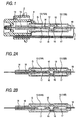
- the discharge lamp device is structured so that the front and rear end portions of an arc tube 10 are supported and integrated with an insulating base 2 by a lead support 3 which also serves as a conducting path projecting forward of the insulating base 2 and a metallic holding member 4 fixed to the front face of the insulating base 2.
- the arc tube 10 is structured so that portions close to a spherical swelling portion of a circular pipe-shaped quartz glass tube W having a spherical swelling portion formed in the middle in the longitudinal direction of a straight extending portion are pinch-sealed to form pinch-sealed portions 13 (a primary pinch-sealed portion 13A and a secondary pinch-sealed portion 13B) having rectangular cross sectional shapes on both end portions of an oval tipless closed glass bulb 12 forming a discharge space.
- pinch-sealed portions 13 a primary pinch-sealed portion 13A and a secondary pinch-sealed portion 13B
- pinch-sealed portions 13 a primary pinch-sealed portion 13A and a secondary pinch-sealed portion 13B
- the arc tube is a mercury-free type in which mercury that is an environmental toxin and is generally enclosed is not enclosed, and the arc tube is made compact.
- tungsten-made electrodes 16 and 16 constituting a discharge electrode are disposed oppositely, and the electrodes 16 and 16 are connected to molybdenum foils 17 sealed to the pinch-sealed portions 13.
- Molybdenum-made lead wires 18 connected to the molybdenum foils 17 are led out from the end portions of the pinch-sealed portions 13, and the rear end side lead wire 18 is inserted through the circular pipe-shaped portion 14 which is a non-pinch-sealed portion and extends to the outside.
- the electrode 16, the molybdenum foil 17, and the lead wire 18 are connected and integrated in series in advance as an electrode assembly, and in a pinch-sealing process for pinch-sealing the portions close to the spherical swelling portion of the quartz glass tube W, regions including the molybdenum foils 17 of the electrode assemblies are pinch-sealed and sealed to the pinch-sealed portions 13.
- the reference symbol G denotes a cylindrical ultraviolet screening shroud glass welded to and integrated with the arc tube 10.
- the ultraviolet screening shroud glass cuts-off ultraviolet components with a wave range harmful to humans in light emitted from the arc tube 10.
- the closed glass bulb 12 In the closed space between the shroud glass G and the arc tube 10, not more than 1 atmosphere of an inert gas or nitrogen is enclosed, and the closed glass bulb 12 is kept at a high temperature.
- the outer diameter and the inner diameter of the closed glass bulb 12 are 6.1 millimeters and 2.5 millimeters, respectively, the internal capacity of the closed glass bulb 12 is 22 ⁇ l, and the electrode 16 has a stepped structure with an entire length of 7.0 millimeters, a thickness of 0.35 millimeters until a point of 1.2 millimeters on the tip end side, and a thickness of 0.3 millimeters on the remaining shaft portion side, and is made of potassium-doped tungsten.
- the arc tube In the arc tube 10, mercury is not enclosed in the closed glass bulb 12, so that the tube voltage is set to be lower (i.e., the tube current is set to be larger) than that of a mercury-contained arc tube. Therefore, the arc tube is used under the condition that the temperature of the arc tube 10 including the pinch-sealed portions 13 becomes higher than that of the mercury-contained arc tube.
- a molybdenum foil doped with TiO 2 or a molybdenum foil coated with TiO 2 is used to enhance a joining strength between the glass and the molybdenum foils 17.
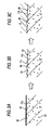
- a molybdenum foil 17 used in the arc tube of the first example a molybdenum foil doped with 2 weight percent of TiO 2 with respect to a total weight of molybdenum and TiO 2 is subjected to surface roughening etching including oxidation and reduction. Accordingly, on the surface thereof, a rough surface 17c having deep and complicated minute unevenness as shown in Fig. 3B is formed.
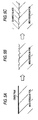
- a molybdenum foil 17 used in the arc tube of the second example a molybdenum foil coated with TiO 2 in a form of discontinuous lands (area ratio: 6.9 ⁇ g/cm2) is subjected to surface roughening etching including oxidation and reduction.
- a rough surface 17c with deep and complicated minute unevenness as shown in Fig. 4B is formed.
- glass is in close contact with the rough surface 17c with deep and complicated minute unevenness on the surface of the molybdenum foil 17, and the joining strength between glass and the molybdenum foil 17 is enhanced.
- etching oxidation and reduction
- the oxide film is removed from the surface of the molybdenum foil, and oxidized molybdenum in the surface layer portion of the molybdenum foil is sublimed, and a rough surface with minute unevenness is formed on the molybdenum foil surface as shown in Fig. 5B .
- the minute unevenness of the molybdenum foil is filled with quartz glass without gaps, and the physical adhesion (mechanical joining strength) at the interface between quartz glass and the molybdenum foil is improved.
- the molybdenum foil 17 used in the arc tube of the first example is a molybdenum foil doped with TiO 2 .
- the surface thereof is covered by an oxide film 17a as shown in Fig. 3A .
- the molybdenum foil 17 is subjected to etching by being put into an oxidation furnace for a predetermined time and then put into a reduction furnace filled with hydrogen gas for a predetermined time. Accordingly, the oxide film 17a is removed from the surface of the molybdenum foil 17, and oxidized molybdenum in the surface layer portion of the molybdenum foil 17 is sublimed.
- TiO 2 particles 20 are not sublimed but are left as they are, and on the surface of the molybdenum foil, as shown in Fig. 3B , a rough surface 17c with minute unevenness is formed. Due to removal of the oxide film 17a, as well as TiO 2 particles 20 originally exposed to the surface of the molybdenum foil 17, TiO 2 particles 20 dispersed inside the molybdenum foil are also exposed to the rough surface 17c according to formation of the rough surface 17c with minute unevenness.
- the molybdenum foil 17 used in the arc tube of the second example is a molybdenum foil coated with TiO 2 in the form of discontinuous lands.
- the surface thereof is covered by an oxide film 17a as shown in Fig. 4A .
- the oxide film 17a is removed from the surface of the molybdenum foil 17, and oxidized molybdenum in the surface layer portion of the molybdenum foil 17 is sublimed.
- the TiO 2 layer 22 is not sublimed but left as it is, and on the molybdenum foil surface, as shown in Fig.
- the TiO 2 layer 22 TiO 2 layer with strong chemical bonding force to quartz glass
- the TiO 2 layer 22 dispersed and exposed to the rough surface 17c of the molybdenum foil 17 improves the chemical adhesion (chemical joining strength) at the interface between quartz glass and the molybdenum foil 17.
- a rough surface 17c with minute unevenness is formed on the molybdenum foil surface.
- the TiO 2 layer 22 is not sublimed but left as it is on the rough surface 17c, so that the TiO 2 layer makes deeper and more complicated the minute unevenness 17b formed on the molybdenum foil surface (than the minute unevenness formed on the rough surface of the related art molybdenum foil of JP-A-2003-86136 ).
- the minute unevenness 17b on the molybdenum foil rough surface is filled with quartz glass without gaps, and the physical adhesion (mechanical joining strength) at the interface between quartz glass and the molybdenum foil 17 is also improved.
- the joining interface between quartz glass and the molybdenum foil 17 in the pinch-sealed portion 13 has adhesion (joining strength) sufficiently resistant to heat stress occurring at the interface.
- a molybdenum foil spool formed by winding a band-like long molybdenum foil is unwound and put into an oxidation furnace and a reduction furnace in order. Accordingly, the surface of the molybdenum foil spool is etched, and the molybdenum foil spool is rewound to obtain a band-like long molybdenum foil spool the surface of which is etched.
- molybdenum foils 17 including the etched surface 17c are formed. The lengths and dimensions of the molybdenum foils may be predetermined.
- the electrode 16 and the lead wire 18 are welded in series to the molybdenum foil 17 having the etched surface 17c, and are integrated together as an electrode assembly.
- a higher oxidation temperature of the molybdenum foil is better because the oxidation becomes faster and the oxidation time becomes shorter. If the oxidation temperature is lower than 300 °C, formation of the oxide film on the surface of the molybdenum foil takes a long time, and this length of time is not practicable. On the other hand, if the oxidation temperature is higher than 550 °C, oxidation becomes excessive and the surface of the molybdenum foil becomes grayish black visually. The molybdenum foil becomes fragile, and weldability to the electrode may deteriorate such that the foil may be cut during pinch-sealing.
- the molybdenum foil be oxidized at a temperature in the range of about 300 °C to about 550 °C.
- the oxidation temperature of the molybdenum foil is most advantageous in the range of about 500 °C to about 550 °C which is substantially equal to the subsequent reduction time.
- oxidation was performed at two temperatures of 500 °C and 550 °C, and in both cases, a rough surface 17c having advantageous properties was obtained.
- Treatments 1, 2, and 3 were obtained at an oxidation temperature of 505 °C. Note that substantially the same data on the life of the arc tube (time until foil floating occurs), the life of the arc tube (time until flickering occurs) and lumen maintenance factor as the data of Treatments 1, 2, and 3 were also obtained in the case of Treatment 1' which was "Oxidized for 65 seconds at 500 °C and reduced with hydrogen for 90 seconds at 630 °C," Treatment 2' which was “Oxidized for 95 seconds at 500 °C and reduced with hydrogen for 90 seconds at 630 °C," Treatment 3' which was "Oxidized for 190 seconds at 500 °C and reduced with hydrogen for 90 seconds at 630 °C".
- Figs. 6A, 6B , 7A, 7B , 8A, 8B and 9 first, concerning the life of the arc tube (time until foil floating occurs), as shown in Figs. 6A and 6B , the time until the foil floating (leak of enclosed substances) occurs exceeds 2000 hours in each of Examples 1 and 2 as shown in Fig. 6B when oxidation and reduction of any of Treatments 1, 2, and 3 are applied. However, only the oxidation and reduction used in Treatment 2 satisfied the life as long as 2500 hours as a standard, in each of Examples 1 and 2.
- the oxidation and reduction shown in Treatment 2 or 3 satisfies the lumen maintenance factor of 80% after 1500 hours elapses, in each of Examples 1 and 2.
- Treatment 2 which was "Oxidized for 65 seconds at 505 °C and reduced with hydrogen for 90 seconds at 630 °C
- Treatment 2' which was "Oxidized for 95 seconds at 500 °C and reduced with hydrogen for 90 seconds at 630 °C”.
- Treatment 2' achieved the same effect as that of Treatment 2. Under these treatment conditions, all of the life of the arc tube (time until foil floating occurs), the life of the arc tube (time until flickering occurs), and the lumen maintenance factor can be satisfied.
- a molybdenum foil doped with 2 weight percent of TiO 2 with respect to the total weight of molybdenum and TiO 2 (first example), and a molybdenum foil coated with TiO 2 in the form of discontinuous lands (area ratio: 6.9 ⁇ g/cm2) (second example) are described.
- the amount of TiO 2 to be doped is advantageously in the range of 0.1 to 3.0 weight percent, and the amount of TiO 2 to be coated is advantageously in the range of area ratio of 6 to 8 ⁇ g/cm2. If the amount of TiO 2 is excessively large, the oxygen component is large and flickering easily occurs, and the lumen maintenance factor decreases. On the contrary, if the amount of TiO 2 is excessively small, the bonding force between the molybdenum foil and glass decreases and foil floating easily occurs, and the life becomes shorter.
- a mercury-free arc tube for a discharge lamp device including:
- a mercury-free arc tube for a discharge lamp device including:
- the molybdenum foil contains TiO 2 molecules dispersed inside (first example), or the surface of the molybdenum foil is coated with TiO 2 in a form of discontinuous lands (second example), and when the molybdenum foil is exposed to the atmosphere, the surface is covered by an oxide film as shown in Fig. 3A and Fig. 4A .
- etching including oxidation and reduction to the molybdenum foil, the oxide film is removed from the surface of the molybdenum foil, and oxidized molybdenum in the surface layer portion of the molybdenum foil is sublimed.
- TiO 2 molecules or the TiO 2 layer in the form of lands which have high chemical bonding strength to quartz glass, and are dispersed and exposed to the rough surface of the molybdenum foil, improve the chemical adhesion (chemical joining strength) at the interface between quartz glass and the molybdenum foil.
- an oxidation temperature of the molybdenum foil in the etching step is set in a range of about 500 °C to about 550 °C.
- the molybdenum foil oxidation temperature is lower than about 300 °C, formation of an oxide film on the surface of the molybdenum foil takes a long time, and this length of time is not practicable. As the temperature becomes higher, the oxidation becomes faster and the oxidation time becomes shorter, so that a higher temperature is preferable.
- the oxidation temperature is high, the depth and the complicatedness of the minute unevenness on the oxidized molybdenum foil surface increase, and the depth and the complicatedness of the minute unevenness on the molybdenum foil surface after being oxidized and reduced also increase. Accordingly, to increase the mechanical joining strength between glass and molybdenum foil, a higher oxidation temperature is better.
- the molybdenum foil is excessively oxidized and becomes fragile (the surface becomes grayish black visually), and the weldability to the electrode may deteriorate and the foil may be cut during pinch-sealing. Accordingly, it is advantageous for the molybdenum foil to be oxidized at a temperature in the range of about 300 °C to about 550 °C. Particularly, when the oxidation temperature is in the range of about 500 °C to about 550 °C, the oxidation time and the reduction time become substantially equal to each other, so that oxidation and reduction can be performed continuously.
- both of chemical adhesion (chemical joining strength) and physical adhesion (mechanical joining strength) at the interface between quartz glass and the molybdenum foil in the pinch-sealed portion are improved, and an arc tube with a longer life in which foil floating does not occur at the pinch-sealed portions can be provided.
- mass production of the arc tube with a longer life in which foil floating does not occur at the pinch-sealed portions becomes possible, and accordingly, the arc tube with a longer life can be provided inexpensively.
Landscapes
- Engineering & Computer Science (AREA)
- Manufacturing & Machinery (AREA)
- Vessels And Coating Films For Discharge Lamps (AREA)
Applications Claiming Priority (1)
| Application Number | Priority Date | Filing Date | Title |
|---|---|---|---|
| JP2008236365A JP2010073330A (ja) | 2008-09-16 | 2008-09-16 | 放電ランプ装置用水銀フリーアークチューブおよび同アークチューブの製造方法 |
Publications (3)
| Publication Number | Publication Date |
|---|---|
| EP2164093A2 true EP2164093A2 (de) | 2010-03-17 |
| EP2164093A3 EP2164093A3 (de) | 2010-07-07 |
| EP2164093B1 EP2164093B1 (de) | 2011-11-09 |
Family
ID=41100466
Family Applications (1)
| Application Number | Title | Priority Date | Filing Date |
|---|---|---|---|
| EP09169451A Not-in-force EP2164093B1 (de) | 2008-09-16 | 2009-09-04 | Quecksilberfreie Bogenentladungsröhre für Entladungslampenvorrichtung und Herstellungsverfahren dafür |
Country Status (4)
| Country | Link |
|---|---|
| US (1) | US8148902B2 (de) |
| EP (1) | EP2164093B1 (de) |
| JP (1) | JP2010073330A (de) |
| AT (1) | ATE533174T1 (de) |
Cited By (1)
| Publication number | Priority date | Publication date | Assignee | Title |
|---|---|---|---|---|
| EP2214195A3 (de) * | 2009-01-29 | 2011-05-04 | Koito Manufacturing Co., Ltd. | Quecksilberfreie Bogenentladungsröhre für Entladungslampeneinheit |
Families Citing this family (1)
| Publication number | Priority date | Publication date | Assignee | Title |
|---|---|---|---|---|
| JP5903646B2 (ja) * | 2011-03-28 | 2016-04-13 | パナソニックIpマネジメント株式会社 | 閃光放電管 |
Citations (2)
| Publication number | Priority date | Publication date | Assignee | Title |
|---|---|---|---|---|
| JP2002033079A (ja) | 2000-05-18 | 2002-01-31 | Plansee Ag | 電灯の製造方法 |
| JP2003086136A (ja) | 2001-09-07 | 2003-03-20 | Koito Mfg Co Ltd | 放電ランプアークチューブおよび同アークチューブの製造方法 |
Family Cites Families (14)
| Publication number | Priority date | Publication date | Assignee | Title |
|---|---|---|---|---|
| JPH0323655Y2 (de) * | 1985-11-15 | 1991-05-23 | ||
| EP0767968B1 (de) * | 1995-04-27 | 1999-09-22 | Koninklijke Philips Electronics N.V. | Gesockelte elektrische lampe |
| US7477120B2 (en) * | 2001-08-13 | 2009-01-13 | Bose Corporation | Transformer shielding |
| JP3687582B2 (ja) * | 2001-09-12 | 2005-08-24 | ウシオ電機株式会社 | 放電ランプ |
| DE10200005A1 (de) * | 2002-01-02 | 2003-07-17 | Philips Intellectual Property | Verfahren zur Herstellung einer Folie aus Molybdän und Titanoxid (TiO2) zum Einsetzen in einen Glaskolben |
| JP2003317659A (ja) * | 2002-04-25 | 2003-11-07 | Ushio Inc | 放電ランプ |
| WO2003105177A2 (en) * | 2002-06-07 | 2003-12-18 | Koninklijke Philips Electronics N.V. | Electric lamp |
| DE10245922A1 (de) * | 2002-10-02 | 2004-04-15 | Philips Intellectual Property & Standards Gmbh | Hochdruckgasentladungslampe |
| JP4231380B2 (ja) * | 2003-10-16 | 2009-02-25 | 株式会社アライドマテリアル | 電球及びそれに用いられる電流導体 |
| KR101135870B1 (ko) * | 2004-07-06 | 2012-04-19 | 코닌클리즈케 필립스 일렉트로닉스 엔.브이. | 개선된 램프 특성을 갖는 램프 |
| KR101140746B1 (ko) * | 2004-09-30 | 2012-05-15 | 코닌클리즈케 필립스 일렉트로닉스 엔.브이. | 밀봉 호일을 갖는 전기 램프 |
| JP4509754B2 (ja) * | 2004-12-02 | 2010-07-21 | 株式会社小糸製作所 | 放電ランプ装置用アークチューブおよび同アークチューブの製造方法 |
| JP2007134055A (ja) * | 2005-11-08 | 2007-05-31 | Koito Mfg Co Ltd | 放電ランプ装置用アークチューブ |
| US7759871B2 (en) * | 2005-12-16 | 2010-07-20 | General Electric Company | High temperature seal for electric lamp |
-
2008
- 2008-09-16 JP JP2008236365A patent/JP2010073330A/ja active Pending
-
2009
- 2009-09-04 AT AT09169451T patent/ATE533174T1/de active
- 2009-09-04 EP EP09169451A patent/EP2164093B1/de not_active Not-in-force
- 2009-09-10 US US12/557,133 patent/US8148902B2/en not_active Expired - Fee Related
Patent Citations (2)
| Publication number | Priority date | Publication date | Assignee | Title |
|---|---|---|---|---|
| JP2002033079A (ja) | 2000-05-18 | 2002-01-31 | Plansee Ag | 電灯の製造方法 |
| JP2003086136A (ja) | 2001-09-07 | 2003-03-20 | Koito Mfg Co Ltd | 放電ランプアークチューブおよび同アークチューブの製造方法 |
Cited By (2)
| Publication number | Priority date | Publication date | Assignee | Title |
|---|---|---|---|---|
| EP2214195A3 (de) * | 2009-01-29 | 2011-05-04 | Koito Manufacturing Co., Ltd. | Quecksilberfreie Bogenentladungsröhre für Entladungslampeneinheit |
| US8174195B2 (en) | 2009-01-29 | 2012-05-08 | Koito Manufacturing Co., Ltd. | Mercury-free arc tube for discharge lamp unit |
Also Published As
| Publication number | Publication date |
|---|---|
| ATE533174T1 (de) | 2011-11-15 |
| US8148902B2 (en) | 2012-04-03 |
| EP2164093A3 (de) | 2010-07-07 |
| US20100066246A1 (en) | 2010-03-18 |
| EP2164093B1 (de) | 2011-11-09 |
| JP2010073330A (ja) | 2010-04-02 |
Similar Documents
| Publication | Publication Date | Title |
|---|---|---|
| JP4424394B2 (ja) | エキシマランプ | |
| JP3648184B2 (ja) | 放電ランプアークチューブおよび同アークチューブの製造方法 | |
| EP2164093B1 (de) | Quecksilberfreie Bogenentladungsröhre für Entladungslampenvorrichtung und Herstellungsverfahren dafür | |
| JPWO2008129745A1 (ja) | 箔シールランプ | |
| CN103748657B (zh) | 车辆用的无汞金属卤化物灯及金属卤化物灯装置 | |
| JP4509754B2 (ja) | 放電ランプ装置用アークチューブおよび同アークチューブの製造方法 | |
| KR20110044695A (ko) | 엑시머 램프 | |
| US9053921B2 (en) | High-pressure discharge lamp having an ignition aid | |
| US20080203920A1 (en) | Lamp Having Molybdenum Alloy Lamp Components | |
| JP4413713B2 (ja) | メタルハライドランプ | |
| JP2001266794A (ja) | 高圧放電ランプおよび照明装置 | |
| JP2006140135A (ja) | 放電ランプ装置用アークチューブ | |
| JP4719105B2 (ja) | メタルハライドランプ | |
| JP5090244B2 (ja) | 放電ランプおよび放電ランプ装置 | |
| JP2005183164A (ja) | 放電ランプ装置用アークチューブ | |
| JP3576133B2 (ja) | 高圧放電ランプ | |
| EP2378541B1 (de) | Herstellung einer Bogenentladungsröhre mit verbesserten Quetschdichtungen | |
| JP4449566B2 (ja) | 放電ランプ | |
| JP5956790B2 (ja) | 放電ランプ | |
| JP2011090945A (ja) | 冷陰極蛍光ランプ用リード線とワイヤーハーネスとの接続構造 | |
| JP2006147298A (ja) | 低圧放電ランプ用給電部材 | |
| JP2007087683A (ja) | メタルハライドランプ | |
| JP2014078401A (ja) | 管状ヒータおよび加熱モジュール | |
| JP2008021503A (ja) | 自動車前照灯用メタルハライドランプ | |
| JP2006134656A (ja) | メタルハライドランプ |
Legal Events
| Date | Code | Title | Description |
|---|---|---|---|
| PUAI | Public reference made under article 153(3) epc to a published international application that has entered the european phase |
Free format text: ORIGINAL CODE: 0009012 |
|
| 17P | Request for examination filed |
Effective date: 20090904 |
|
| AK | Designated contracting states |
Kind code of ref document: A2 Designated state(s): AT BE BG CH CY CZ DE DK EE ES FI FR GB GR HR HU IE IS IT LI LT LU LV MC MK MT NL NO PL PT RO SE SI SK SM TR |
|
| AX | Request for extension of the european patent |
Extension state: AL BA RS |
|
| PUAL | Search report despatched |
Free format text: ORIGINAL CODE: 0009013 |
|
| AK | Designated contracting states |
Kind code of ref document: A3 Designated state(s): AT BE BG CH CY CZ DE DK EE ES FI FR GB GR HR HU IE IS IT LI LT LU LV MC MK MT NL NO PL PT RO SE SI SK SM TR |
|
| AX | Request for extension of the european patent |
Extension state: AL BA RS |
|
| RIC1 | Information provided on ipc code assigned before grant |
Ipc: H01J 9/28 20060101ALI20100602BHEP Ipc: H01J 5/46 20060101ALI20100602BHEP Ipc: H01J 61/36 20060101AFI20090930BHEP |
|
| GRAP | Despatch of communication of intention to grant a patent |
Free format text: ORIGINAL CODE: EPIDOSNIGR1 |
|
| RIC1 | Information provided on ipc code assigned before grant |
Ipc: H01J 9/28 20060101ALI20110323BHEP Ipc: H01J 5/46 20060101ALI20110323BHEP Ipc: H01J 61/36 20060101AFI20110323BHEP |
|
| GRAS | Grant fee paid |
Free format text: ORIGINAL CODE: EPIDOSNIGR3 |
|
| GRAA | (expected) grant |
Free format text: ORIGINAL CODE: 0009210 |
|
| AK | Designated contracting states |
Kind code of ref document: B1 Designated state(s): AT BE BG CH CY CZ DE DK EE ES FI FR GB GR HR HU IE IS IT LI LT LU LV MC MK MT NL NO PL PT RO SE SI SK SM TR |
|
| REG | Reference to a national code |
Ref country code: GB Ref legal event code: FG4D |
|
| REG | Reference to a national code |
Ref country code: CH Ref legal event code: EP |
|
| REG | Reference to a national code |
Ref country code: IE Ref legal event code: FG4D |
|
| REG | Reference to a national code |
Ref country code: DE Ref legal event code: R096 Ref document number: 602009003563 Country of ref document: DE Effective date: 20120105 |
|
| REG | Reference to a national code |
Ref country code: NL Ref legal event code: VDEP Effective date: 20111109 |
|
| LTIE | Lt: invalidation of european patent or patent extension |
Effective date: 20111109 |
|
| PG25 | Lapsed in a contracting state [announced via postgrant information from national office to epo] |
Ref country code: IS Free format text: LAPSE BECAUSE OF FAILURE TO SUBMIT A TRANSLATION OF THE DESCRIPTION OR TO PAY THE FEE WITHIN THE PRESCRIBED TIME-LIMIT Effective date: 20120309 Ref country code: LT Free format text: LAPSE BECAUSE OF FAILURE TO SUBMIT A TRANSLATION OF THE DESCRIPTION OR TO PAY THE FEE WITHIN THE PRESCRIBED TIME-LIMIT Effective date: 20111109 Ref country code: NO Free format text: LAPSE BECAUSE OF FAILURE TO SUBMIT A TRANSLATION OF THE DESCRIPTION OR TO PAY THE FEE WITHIN THE PRESCRIBED TIME-LIMIT Effective date: 20120209 |
|
| PG25 | Lapsed in a contracting state [announced via postgrant information from national office to epo] |
Ref country code: SE Free format text: LAPSE BECAUSE OF FAILURE TO SUBMIT A TRANSLATION OF THE DESCRIPTION OR TO PAY THE FEE WITHIN THE PRESCRIBED TIME-LIMIT Effective date: 20111109 Ref country code: GR Free format text: LAPSE BECAUSE OF FAILURE TO SUBMIT A TRANSLATION OF THE DESCRIPTION OR TO PAY THE FEE WITHIN THE PRESCRIBED TIME-LIMIT Effective date: 20120210 Ref country code: NL Free format text: LAPSE BECAUSE OF FAILURE TO SUBMIT A TRANSLATION OF THE DESCRIPTION OR TO PAY THE FEE WITHIN THE PRESCRIBED TIME-LIMIT Effective date: 20111109 Ref country code: LV Free format text: LAPSE BECAUSE OF FAILURE TO SUBMIT A TRANSLATION OF THE DESCRIPTION OR TO PAY THE FEE WITHIN THE PRESCRIBED TIME-LIMIT Effective date: 20111109 Ref country code: PL Free format text: LAPSE BECAUSE OF FAILURE TO SUBMIT A TRANSLATION OF THE DESCRIPTION OR TO PAY THE FEE WITHIN THE PRESCRIBED TIME-LIMIT Effective date: 20111109 Ref country code: SI Free format text: LAPSE BECAUSE OF FAILURE TO SUBMIT A TRANSLATION OF THE DESCRIPTION OR TO PAY THE FEE WITHIN THE PRESCRIBED TIME-LIMIT Effective date: 20111109 Ref country code: PT Free format text: LAPSE BECAUSE OF FAILURE TO SUBMIT A TRANSLATION OF THE DESCRIPTION OR TO PAY THE FEE WITHIN THE PRESCRIBED TIME-LIMIT Effective date: 20120309 Ref country code: BE Free format text: LAPSE BECAUSE OF FAILURE TO SUBMIT A TRANSLATION OF THE DESCRIPTION OR TO PAY THE FEE WITHIN THE PRESCRIBED TIME-LIMIT Effective date: 20111109 Ref country code: HR Free format text: LAPSE BECAUSE OF FAILURE TO SUBMIT A TRANSLATION OF THE DESCRIPTION OR TO PAY THE FEE WITHIN THE PRESCRIBED TIME-LIMIT Effective date: 20111109 |
|
| PG25 | Lapsed in a contracting state [announced via postgrant information from national office to epo] |
Ref country code: CY Free format text: LAPSE BECAUSE OF FAILURE TO SUBMIT A TRANSLATION OF THE DESCRIPTION OR TO PAY THE FEE WITHIN THE PRESCRIBED TIME-LIMIT Effective date: 20111109 |
|
| PG25 | Lapsed in a contracting state [announced via postgrant information from national office to epo] |
Ref country code: DK Free format text: LAPSE BECAUSE OF FAILURE TO SUBMIT A TRANSLATION OF THE DESCRIPTION OR TO PAY THE FEE WITHIN THE PRESCRIBED TIME-LIMIT Effective date: 20111109 Ref country code: CZ Free format text: LAPSE BECAUSE OF FAILURE TO SUBMIT A TRANSLATION OF THE DESCRIPTION OR TO PAY THE FEE WITHIN THE PRESCRIBED TIME-LIMIT Effective date: 20111109 Ref country code: BG Free format text: LAPSE BECAUSE OF FAILURE TO SUBMIT A TRANSLATION OF THE DESCRIPTION OR TO PAY THE FEE WITHIN THE PRESCRIBED TIME-LIMIT Effective date: 20120209 Ref country code: SK Free format text: LAPSE BECAUSE OF FAILURE TO SUBMIT A TRANSLATION OF THE DESCRIPTION OR TO PAY THE FEE WITHIN THE PRESCRIBED TIME-LIMIT Effective date: 20111109 Ref country code: EE Free format text: LAPSE BECAUSE OF FAILURE TO SUBMIT A TRANSLATION OF THE DESCRIPTION OR TO PAY THE FEE WITHIN THE PRESCRIBED TIME-LIMIT Effective date: 20111109 |
|
| PG25 | Lapsed in a contracting state [announced via postgrant information from national office to epo] |
Ref country code: IT Free format text: LAPSE BECAUSE OF FAILURE TO SUBMIT A TRANSLATION OF THE DESCRIPTION OR TO PAY THE FEE WITHIN THE PRESCRIBED TIME-LIMIT Effective date: 20111109 Ref country code: RO Free format text: LAPSE BECAUSE OF FAILURE TO SUBMIT A TRANSLATION OF THE DESCRIPTION OR TO PAY THE FEE WITHIN THE PRESCRIBED TIME-LIMIT Effective date: 20111109 |
|
| PLBE | No opposition filed within time limit |
Free format text: ORIGINAL CODE: 0009261 |
|
| STAA | Information on the status of an ep patent application or granted ep patent |
Free format text: STATUS: NO OPPOSITION FILED WITHIN TIME LIMIT |
|
| REG | Reference to a national code |
Ref country code: AT Ref legal event code: MK05 Ref document number: 533174 Country of ref document: AT Kind code of ref document: T Effective date: 20111109 |
|
| 26N | No opposition filed |
Effective date: 20120810 |
|
| REG | Reference to a national code |
Ref country code: DE Ref legal event code: R097 Ref document number: 602009003563 Country of ref document: DE Effective date: 20120810 |
|
| PG25 | Lapsed in a contracting state [announced via postgrant information from national office to epo] |
Ref country code: AT Free format text: LAPSE BECAUSE OF FAILURE TO SUBMIT A TRANSLATION OF THE DESCRIPTION OR TO PAY THE FEE WITHIN THE PRESCRIBED TIME-LIMIT Effective date: 20111109 |
|
| PG25 | Lapsed in a contracting state [announced via postgrant information from national office to epo] |
Ref country code: ES Free format text: LAPSE BECAUSE OF FAILURE TO SUBMIT A TRANSLATION OF THE DESCRIPTION OR TO PAY THE FEE WITHIN THE PRESCRIBED TIME-LIMIT Effective date: 20120220 Ref country code: MC Free format text: LAPSE BECAUSE OF NON-PAYMENT OF DUE FEES Effective date: 20120930 |
|
| REG | Reference to a national code |
Ref country code: IE Ref legal event code: MM4A |
|
| PG25 | Lapsed in a contracting state [announced via postgrant information from national office to epo] |
Ref country code: FI Free format text: LAPSE BECAUSE OF FAILURE TO SUBMIT A TRANSLATION OF THE DESCRIPTION OR TO PAY THE FEE WITHIN THE PRESCRIBED TIME-LIMIT Effective date: 20111109 |
|
| PG25 | Lapsed in a contracting state [announced via postgrant information from national office to epo] |
Ref country code: IE Free format text: LAPSE BECAUSE OF NON-PAYMENT OF DUE FEES Effective date: 20120904 |
|
| PGFP | Annual fee paid to national office [announced via postgrant information from national office to epo] |
Ref country code: DE Payment date: 20130829 Year of fee payment: 5 |
|
| PG25 | Lapsed in a contracting state [announced via postgrant information from national office to epo] |
Ref country code: MT Free format text: LAPSE BECAUSE OF FAILURE TO SUBMIT A TRANSLATION OF THE DESCRIPTION OR TO PAY THE FEE WITHIN THE PRESCRIBED TIME-LIMIT Effective date: 20111109 |
|
| PGFP | Annual fee paid to national office [announced via postgrant information from national office to epo] |
Ref country code: FR Payment date: 20130910 Year of fee payment: 5 Ref country code: GB Payment date: 20130904 Year of fee payment: 5 |
|
| PG25 | Lapsed in a contracting state [announced via postgrant information from national office to epo] |
Ref country code: TR Free format text: LAPSE BECAUSE OF FAILURE TO SUBMIT A TRANSLATION OF THE DESCRIPTION OR TO PAY THE FEE WITHIN THE PRESCRIBED TIME-LIMIT Effective date: 20111109 |
|
| REG | Reference to a national code |
Ref country code: CH Ref legal event code: PL |
|
| PG25 | Lapsed in a contracting state [announced via postgrant information from national office to epo] |
Ref country code: LU Free format text: LAPSE BECAUSE OF NON-PAYMENT OF DUE FEES Effective date: 20120904 Ref country code: SM Free format text: LAPSE BECAUSE OF FAILURE TO SUBMIT A TRANSLATION OF THE DESCRIPTION OR TO PAY THE FEE WITHIN THE PRESCRIBED TIME-LIMIT Effective date: 20111109 |
|
| PG25 | Lapsed in a contracting state [announced via postgrant information from national office to epo] |
Ref country code: CH Free format text: LAPSE BECAUSE OF NON-PAYMENT OF DUE FEES Effective date: 20130930 Ref country code: LI Free format text: LAPSE BECAUSE OF NON-PAYMENT OF DUE FEES Effective date: 20130930 Ref country code: HU Free format text: LAPSE BECAUSE OF FAILURE TO SUBMIT A TRANSLATION OF THE DESCRIPTION OR TO PAY THE FEE WITHIN THE PRESCRIBED TIME-LIMIT Effective date: 20090904 |
|
| REG | Reference to a national code |
Ref country code: DE Ref legal event code: R119 Ref document number: 602009003563 Country of ref document: DE |
|
| GBPC | Gb: european patent ceased through non-payment of renewal fee |
Effective date: 20140904 |
|
| REG | Reference to a national code |
Ref country code: DE Ref legal event code: R119 Ref document number: 602009003563 Country of ref document: DE Effective date: 20150401 |
|
| REG | Reference to a national code |
Ref country code: FR Ref legal event code: ST Effective date: 20150529 |
|
| PG25 | Lapsed in a contracting state [announced via postgrant information from national office to epo] |
Ref country code: GB Free format text: LAPSE BECAUSE OF NON-PAYMENT OF DUE FEES Effective date: 20140904 Ref country code: MK Free format text: LAPSE BECAUSE OF FAILURE TO SUBMIT A TRANSLATION OF THE DESCRIPTION OR TO PAY THE FEE WITHIN THE PRESCRIBED TIME-LIMIT Effective date: 20111109 Ref country code: DE Free format text: LAPSE BECAUSE OF NON-PAYMENT OF DUE FEES Effective date: 20150401 |
|
| PG25 | Lapsed in a contracting state [announced via postgrant information from national office to epo] |
Ref country code: FR Free format text: LAPSE BECAUSE OF NON-PAYMENT OF DUE FEES Effective date: 20140930 |