EP2163774B1 - Hydrodynamic fluid film bearing - Google Patents
Hydrodynamic fluid film bearing Download PDFInfo
- Publication number
- EP2163774B1 EP2163774B1 EP09014920A EP09014920A EP2163774B1 EP 2163774 B1 EP2163774 B1 EP 2163774B1 EP 09014920 A EP09014920 A EP 09014920A EP 09014920 A EP09014920 A EP 09014920A EP 2163774 B1 EP2163774 B1 EP 2163774B1
- Authority
- EP
- European Patent Office
- Prior art keywords
- foil
- assembly
- key slot
- end tab
- top foil
- Prior art date
- Legal status (The legal status is an assumption and is not a legal conclusion. Google has not performed a legal analysis and makes no representation as to the accuracy of the status listed.)
- Active
Links
Images


Classifications
-
- F—MECHANICAL ENGINEERING; LIGHTING; HEATING; WEAPONS; BLASTING
- F16—ENGINEERING ELEMENTS AND UNITS; GENERAL MEASURES FOR PRODUCING AND MAINTAINING EFFECTIVE FUNCTIONING OF MACHINES OR INSTALLATIONS; THERMAL INSULATION IN GENERAL
- F16C—SHAFTS; FLEXIBLE SHAFTS; ELEMENTS OR CRANKSHAFT MECHANISMS; ROTARY BODIES OTHER THAN GEARING ELEMENTS; BEARINGS
- F16C17/00—Sliding-contact bearings for exclusively rotary movement
- F16C17/02—Sliding-contact bearings for exclusively rotary movement for radial load only
- F16C17/024—Sliding-contact bearings for exclusively rotary movement for radial load only with flexible leaves to create hydrodynamic wedge, e.g. radial foil bearings
-
- F—MECHANICAL ENGINEERING; LIGHTING; HEATING; WEAPONS; BLASTING
- F16—ENGINEERING ELEMENTS AND UNITS; GENERAL MEASURES FOR PRODUCING AND MAINTAINING EFFECTIVE FUNCTIONING OF MACHINES OR INSTALLATIONS; THERMAL INSULATION IN GENERAL
- F16C—SHAFTS; FLEXIBLE SHAFTS; ELEMENTS OR CRANKSHAFT MECHANISMS; ROTARY BODIES OTHER THAN GEARING ELEMENTS; BEARINGS
- F16C43/00—Assembling bearings
- F16C43/02—Assembling sliding-contact bearings
Definitions
- the present invention relates to hydrodynamic fluid film bearing assemblies, and methods of manufacturing the same.
- Hydrodynamic fluid film journal bearings also called journal air bearings or foil bearings
- a typical prior art bearing assembly of this type includes a journal sleeve, a bump foil, an intermediate foil, and a top foil.
- the bump foil, the intermediate foil and the top foil are wrapped inside the journal sleeve in a substantially cylindrical shape, and those foils are positioned between the journal sleeve and the rotatable component.
- Each foil has an end that is engaged to the journal sleeve, and can have another end that is free (i.e., not engaged to the journal sleeve).
- rotation of the rotatable component causes a working fluid to form a cushion (often referred to as an "air bearing") that supports the rotatable component with little or no direct contact between the rotatable component and the foils of the bearing.
- Skewing refers to movement of a free end of a foil in a generally axial direction. Skewing causes a foil to become more conically shaped, which reduces diameters inside the foil and causes tightening relative to the rotatable component supported by the bearing. Tightening of foils is undesirable because it can interfere with working fluid (or cooling fluid) movement, and can increase torque on the rotatable component.
- US 4552466 discloses a hydrodynamic fluid film journal bearing assembly comprising a journal sleeve having an inner diameter surface and an opposite outer diameter surface a key slot formed in the journal sleeve, wherein the key slot extends between the inner diameter surface and the opposite outer diameter surface of the journal sleeve, and wherein the key slot has an elongate rectangular shape that is arranged in a substantially axial direction with respect to an axis defined by the journal sleeve; and a first foil projecting into the key slot such that the key slot retains the first foil relative to the journal sleeve.
- the present invention is characterised in that the first foil comprises: a cutout window formed adjacent to a bent region that projects into the key slot; and a first end tab formed at a free end of the first foil, wherein the first end tab extends into the cutout window to reduce skewing of the first foil.
- the present invention in general, provides an improved hydrodynamic fluid film journal bearing assembly that is relatively simple and easy to fabricate and assemble. Furthermore, the improved hydrodynamic fluid film journal bearing assembly of the present invention helps to reduce or eliminate problems of "skewing", which refers to undesirable movement of a free end of a foil of the bearing assembly in a generally axial direction. In addition, the configuration of the improved hydrodynamic fluid film journal bearing assembly allows for reworking of components during fabrication and assembly, thereby helping to reduce the amount of scrap produced and to reduce manufacturing costs.
- FIG. 1 is an end view of a hydrodynamic fluid film journal bearing assembly 10.
- FIG. 2 is a cross-sectional view of the bearing assembly 10, taken along line 2-2 of FIG. 1 .
- the bearing assembly 10 includes a journal sleeve 12 that defines an outer diameter surface 14, an inner diameter surface 16, a first end 18, and a second end 20.
- the journal sleeve 12 is arranged about a central axis A. It should be noted that the journal sleeve 12 can have a conventional cylindrical shape, or alternatively can be shaped with a weight-reduced profile.
- FIG. 3 is a top view of the exterior of the bearing assembly 10 (structures that would otherwise be visible through the key slot 22 have been omitted in FIG. 3 for clarity).
- the key slot 22 has an elongate, substantially rectangular shape that is arranged generally parallel to the axis A.
- the key slot 22 has a first end 24 that is spaced from the first end 18 of the journal sleeve 12 a distance D 1 , and has a second end 26 that is spaced from the second end 20 of the journal sleeve 12 a distance D 2 .
- distance D 1 is greater than distance D 2 , such that the key slot 22 is axially (or longitudinally) offset with respect to a length of the journal sleeve 12.
- the key slot 22 can be offset in this manner for assembly foolproofing purposes, as explained further below.
- the key slot 22 can be axially centered relative to the journal sleeve 12.
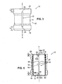
- FIG. 4 is an enlarged cross-sectional view of the bearing assembly 10, taken along line 4-4 of FIG. 2 .
- the bearing assembly 10 further includes a bump foil 28, an intermediate foil 30 and a top foil 32.
- the bump foil 28, the intermediate foil 30 and the top foil 32 are each thin sheets of material (e.g., nickel-based alloys or steel) wrapped in a generally cylindrical shape and positioned in a bore of the journal sleeve 12.
- the bump foil 28 is corrugated, allowing a working fluid or cooling fluid to flow through spaces formed between adjacent corrugations.
- the bump foil 28 is positioned adjacent to the inner diameter surface 16 of the journal sleeve 12, and has a bent end 34 that extends radially outward at least partially into the key slot 22 in order to engage the key slot 22 and retain the bump foil 30 relative to the journal sleeve 12.
- the bent end 34 of the bump foil 28 can be angled at approximately 90° with respect to an adjacent, generally cylindrical portion of the bump foil 28.
- the intermediate foil 30 is positioned adjacent to and radially inward from the bump foil 28, and the top foil is positioned adjacent to and radially inward from the intermediate foil 30.
- the intermediate foil 30 and the top foil 32 are joined together at a bent region 38 that extends radially outward at least partially into the key slot 22, in order to engage the key slot 22 and retain both the intermediate and top foils 30 and 32 relative to the journal sleeve 12.
- the bent region 38 can be angled at approximately 90° with respect to adjacent, generally cylindrical portions of the intermediate foil 30 and the top foil 32.
- the intermediate foil 30 and the top foil 32 are formed by opposite end portions of a single integral sheet that join at the bent region 38, located in a middle portion of the integral sheet.
- the intermediate foil 30 and the top foil 32 are formed from separate sheets connected together at the bent region 38 using welding, brazing or other suitable attachment means.
- a rotatable component like a shaft can be positioned inside the bearing assembly, radially inward from the top foil 32. Such a rotatable component would typically rotate clockwise with respect to the cross-section of the bearing assembly 10 shown in FIG. 4 .
- a radially inner surface of the top foil 32 exposed to the rotatable component can optionally be coated with a suitable dry film lubricant. Use of such a dry film lubricant can reduce friction caused by the rotatable component when accelerating to operating speed, when decelerating from operating speed, when stopped, and when subject to incidental contact with the top foil 32 during regular operation.
- FIG. 5 is a cross-sectional view of the bearing assembly 10, taken along line 5-5 of FIG. 1 .
- the top foil 32 defines a free end 40, and opposite first and second side edges 42 and 44, respectively.
- a first end tab 46 extends from the free end 40 of the top foil 32 at the first side edge 42
- a second end tab 48 extends from the free end 40 of the top foil 32 at the second side edge 44.
- each of the end tabs 46 and 48 is generally rectangular in shape with rounded corners, and is positioned such that axially outer edges 46A and 48A of the first and second end tabs 46 and 48 align with the first and second side edges 42 and 44, respectively.
- the first end tab 46 has an axial (or longitudinal) dimension D 3
- the second end tab 48 has an axial dimension D 4 .
- D 3 is greater than D 4 for assembly foolproofing purposes.
- a ratio of end tab dimensions D 3 to D 4 can be proportional to a ratio of key slot offset dimensions D 1 to D 2 .
- a first cutout window 50 is formed in the top foil 32 at the first side edge 42 adjacent to the bent region 38
- a second cutout window 52 is formed in the top foil 32 at the second side edge 44 adjacent to the bent region 38.
- the first and second cutout windows 50 and 52 in the top foil 32 have shapes that correspond to the shapes of the first and second end tabs 46 and 48, respectively.
- the cutout windows 50 and 52 are each generally rectangular in shape.
- first and second bump foil cutout windows can be formed at opposite edges of the bump foil 28 adjacent to the bend end 34. These bump foil cutout windows can have shapes that correspond to those of the first and second cutout windows 50 and 52 in the top foil 32, and can be aligned with first and second cutout windows 50 and 52 in the top foil 32 as well.
- Engagement edges 50E and 52E are defined in the top foil 30 at the first and second cutout windows 50 and 52, respectively.
- the engagement edges 50E and 52E are arranged generally perpendicular to the axis A, and extend along the top foil 30 through at least a portion of the bent region 38.
- the first and second end tabs 46 and 48 are each inserted into the first and second cutout windows 50 and 52, respectively, in the top foil 32.
- the end tabs 46 and 48 are each "straight" in that both generally retain the substantially cylindrical shape of the top foil 32.
- This "straight" end tab configuration eliminates the necessity of permanently bending the end tabs 46 and 48 when fabricating and assembling the bearing assembly 10, which can reduce the complexity of fabrication and assembly processes and thereby reduce costs.
- cutout windows 50 and 52 can be slightly larger than those of the end tabs 46 and 48 in order to allow a gap to be formed between those structures at a suitably small tolerance for assembly.
- the end tabs 46 and 48 can further extend into the bump foil cutout windows and expose the end tabs 46 and 48 to the inner diameter surface 16 of the journal sleeve 12, allowing contact therebetween.
- a selected one of the cutout windows 50 can optionally have a generally circumferential dimension that is smaller than a generally circumferential dimension of the corresponding end tab 46, so that insertion of the end tab 46 into that selected cutout window 50 must be done generally axially from the first end 18 of the journal sleeve 12.
- the other cutout window 52 must then generally be larger than the corresponding end tab 48 in a generally circumferential dimension to enable generally radial insertion without deforming the top foil 32.
- cutout window 50 allows the selected cutout window 50 to be smaller for better aerodynamic performance and less loss of pressurized working fluid during bearing assembly 10 operation, as well as providing further assembly foolproofing benefits. It should be understood that either cutout window 50 or 52 and corresponding end tab 46 or 48 could have this configuration in alternative embodiments.
- FIG. 6 is a flow chart of a method of fabricating and assembling the bearing assembly 10.
- the method includes forming the bump foil 28, the intermediate foil 30 and the top foil 32 (step 100).
- the intermediate foil 30 and the top foil 32 can be made from separate sheets attached together or can be a made from a unitary sheet.
- Forming the foils at step 100 can include cutting the foils to shape, and defining all cutout windows (e.g., through stamping, punching, electrical discharge machining, or other suitable processes).
- the formed foils are then bent (step 102), which can include forming corrugations and a bent end 34 in the bump foil 28, and forming the bent region 38 where the intermediate foil 30 and the top foil 32 join.
- bending at step 102 does not require bending the first and second end tabs 46 and 48 of the top foil 32. Bending the end tabs 46 and 48 adds to the complexity of manufacturing operations. Also, such bending is permanent and cannot be readily undone to rework a selected part. By eliminating the need to bend the end tabs 46 and 48 according to the present invention, the top foil 32 can be more readily reworked during fabrication and assembly of the bearing assembly 10, thereby helping to reduce the amount of scrap produced and to reduce manufacturing costs.
- the method includes machining the key slot 22 in the journal sleeve 12 (step 104). Electrical discharge machining (EDM) techniques or cutter wheels can be used to form the key slot 22. Because the key slot 22 can have a relatively simple shape and is formed all the way through the journal sleeve 12 between its outer and inner diameter surfaces 14 and 16, EDM techniques can be performed from either the exterior or interior of the journal sleeve 12 in a relatively simple manner and without undesired heating that can cause runout between the outer and inner diameter surfaces 14 and 16. The key slot 22 is also relatively small, having a relatively short axial length. These features of the present invention represent a substantial simplification over complicated techniques required to form complex keyways in prior art hydrodynamic fluid film journal bearing assemblies. Although shown in FIG.
- journal sleeve 12 can be formed using conventional techniques.
- the foils can then be wrapped and inserted into the journal sleeve 12.
- the bump foil 28 is wrapped in a generally cylindrical shape and the bent end 34 is at least partially inserted into the key slot 22 (step 106).
- the intermediate foil 30 and the top foil 32 which are joined together, are also wrapped and inserted into the journal sleeve 12 (step 108).
- the intermediate foil 30 and the top foil 32 are reverse rolled upon each other in step 108 to form a generally cylindrical shape, with the top foil 32 located radially inward from the intermediate foil 30.
- the bent region 38 wherein the intermediate foil 30 and the top foil 32 join, is at least partially inserted into the key slot 22 in the journal sleeve 12, and the end tabs 46 and 48 at the free end 40 of the top foil 32 are inserted into the cutout windows 50 and 52 of the top foil 32 (as well as into any cutout windows in the bump foil 28).
- the assembly 10 can be mounted on a support housing on o-rings and a rotatable component (e.g., a shaft) inserted through the bearing assembly 10 in a conventional manner. It should be noted that the fabrication process can include other steps not specifically mentioned above, such as heat treatment.
- the bearing assembly 10 is configured to support a rotatable component for rotation in a particular direction (clockwise with respect to the assembly 10 as shown in cross-section in FIG. 4 ).
- the finished bearing assembly 10 must therefore have its foils 28, 30 and 32 arranged in a particular manner.
- foolproofing features are provided by the bearing assembly 10.
- the key slot 22 is axially (or longitudinally) offset.
- the first and second end tabs 46 and 48 have different axial dimensions. Such foolproofing features help ensure that the bearing assembly 10 can be assembled in only the proper manner, by ensuring that the bent end 34 of the bump foil 28 and the bent region 38 of the joined intermediate and top foils 30 and 32 only fit within the key slot 22 in one orientation.
Landscapes
- Engineering & Computer Science (AREA)
- General Engineering & Computer Science (AREA)
- Mechanical Engineering (AREA)
- Physics & Mathematics (AREA)
- Fluid Mechanics (AREA)
- Support Of The Bearing (AREA)
- Sliding-Contact Bearings (AREA)
Applications Claiming Priority (2)
| Application Number | Priority Date | Filing Date | Title |
|---|---|---|---|
| US11/786,637 US7648279B2 (en) | 2007-04-12 | 2007-04-12 | Journal air bearing |
| EP08250625A EP1980762B1 (en) | 2007-04-12 | 2008-02-22 | Hydrodynamic fluid film bearing |
Related Parent Applications (1)
| Application Number | Title | Priority Date | Filing Date |
|---|---|---|---|
| EP08250625.4 Division | 2008-02-22 |
Publications (2)
| Publication Number | Publication Date |
|---|---|
| EP2163774A1 EP2163774A1 (en) | 2010-03-17 |
| EP2163774B1 true EP2163774B1 (en) | 2011-06-15 |
Family
ID=39537864
Family Applications (2)
| Application Number | Title | Priority Date | Filing Date |
|---|---|---|---|
| EP09014920A Active EP2163774B1 (en) | 2007-04-12 | 2008-02-22 | Hydrodynamic fluid film bearing |
| EP08250625A Active EP1980762B1 (en) | 2007-04-12 | 2008-02-22 | Hydrodynamic fluid film bearing |
Family Applications After (1)
| Application Number | Title | Priority Date | Filing Date |
|---|---|---|---|
| EP08250625A Active EP1980762B1 (en) | 2007-04-12 | 2008-02-22 | Hydrodynamic fluid film bearing |
Country Status (5)
| Country | Link |
|---|---|
| US (1) | US7648279B2 (https=) |
| EP (2) | EP2163774B1 (https=) |
| JP (1) | JP5253866B2 (https=) |
| DE (1) | DE602008002174D1 (https=) |
| ES (2) | ES2367947T3 (https=) |
Families Citing this family (44)
| Publication number | Priority date | Publication date | Assignee | Title |
|---|---|---|---|---|
| JP4840239B2 (ja) | 2007-04-20 | 2011-12-21 | トヨタ自動車株式会社 | 脚式移動ロボットの制御方法及び脚式移動ロボット |
| US8029194B2 (en) * | 2007-06-18 | 2011-10-04 | R&D Dynamics Corporation | Restrained, reverse multi-pad bearing assembly |
| US8100586B2 (en) * | 2008-06-30 | 2012-01-24 | General Electric Company | Fiber optic sensing device and method for monitoring foil bearings |
| US8056792B2 (en) * | 2009-05-05 | 2011-11-15 | Branson Ultrasonics Corporation | Scalloped horn |
| US8496533B2 (en) * | 2010-03-22 | 2013-07-30 | Hamilton Sundstrand Corporation | Journal bearing with dual pass cooling for air machine |
| JP4961485B2 (ja) * | 2010-03-30 | 2012-06-27 | 本田技研工業株式会社 | 動圧型フォイル式気体軸受 |
| US8419283B2 (en) * | 2010-07-28 | 2013-04-16 | Hamilton Sundstrand Corporation | Journal air bearing |
| US8556516B2 (en) | 2010-08-26 | 2013-10-15 | Hamilton Sundstrand Corporation | Compressor bearing cooling inlet plate |
| US8529192B2 (en) | 2010-09-15 | 2013-09-10 | Hamilton Sundstrand Corporation | Thrust bearing shaft for thrust and journal air bearing cooling in a compressor |
| US8622620B2 (en) * | 2010-09-15 | 2014-01-07 | Hamilton Sundstrand Corporation | Shaft for air bearing and motor cooling in compressor |
| US8784048B2 (en) | 2010-12-21 | 2014-07-22 | Hamilton Sundstrand Corporation | Air cycle machine bearing cooling inlet plate |
| US8517665B2 (en) | 2010-12-21 | 2013-08-27 | Hamilton Sundstrand Corporation | Thrust bearing shaft for thrust and journal air bearing cooling in an air machine |
| JP2012197887A (ja) * | 2011-03-22 | 2012-10-18 | Ntn Corp | フォイル軸受およびその製造方法 |
| US8807921B2 (en) | 2011-04-04 | 2014-08-19 | Hamilton Sundstrand Corporation | Journal air bearing for small shaft diameters |
| JP5751062B2 (ja) * | 2011-07-22 | 2015-07-22 | 株式会社Ihi | ラジアルフォイル軸受 |
| US8672768B2 (en) | 2012-04-11 | 2014-03-18 | Hamilton Sundstrand Corporation | Air bearing shaft for ram air fan |
| EP2706245A1 (en) * | 2012-09-06 | 2014-03-12 | Siemens Aktiengesellschaft | Radial gas foil bearing |
| US8734017B1 (en) | 2013-03-08 | 2014-05-27 | Hamilton Sundstrand Corporation | Air bearing shaft |
| US9404556B2 (en) | 2013-03-12 | 2016-08-02 | Waukesha Bearings Corporation | Damper |
| CN104047958B (zh) * | 2013-03-15 | 2017-09-22 | 哈米尔顿森德斯特兰德公司 | 轴承套 |
| US8794838B1 (en) | 2013-03-15 | 2014-08-05 | Hamilton Sundstrand Corporation | Bearing sleeve |
| CN104047965B (zh) * | 2013-03-15 | 2017-09-22 | 哈米尔顿森德斯特兰德公司 | 轴承套 |
| CN104047956B (zh) * | 2013-03-15 | 2017-09-01 | 哈米尔顿森德斯特兰德公司 | 轴承套 |
| US8920032B2 (en) | 2013-03-15 | 2014-12-30 | Hamilton Sundstrand Corporation | Bearing sleeve |
| US8926182B2 (en) | 2013-03-15 | 2015-01-06 | Hamilton Sundstrand Corporation | Bearing sleeve |
| US9028149B2 (en) | 2013-03-15 | 2015-05-12 | Hamilton Sundstrand Corporation | Bearing sleeve |
| US8783952B1 (en) * | 2013-04-03 | 2014-07-22 | Hamilton Sundstrand Corporation | Journal bearing sleeve |
| US9732789B2 (en) | 2014-09-26 | 2017-08-15 | Hamilton Sundstrand Corporation | Journal air bearing with air-film-supply vent |
| US20160208847A1 (en) * | 2015-01-19 | 2016-07-21 | Hamilton Sundstrand Corporation | Quad foil journal air bearing |
| US20170030404A1 (en) * | 2015-07-29 | 2017-02-02 | Hamilton Sundstrand Corporation | Foil bearing with split key |
| WO2017169676A1 (ja) * | 2016-03-30 | 2017-10-05 | Ntn株式会社 | フォイル軸受 |
| JP6828802B2 (ja) | 2017-03-15 | 2021-02-10 | 株式会社Ihi | ラジアルフォイル軸受 |
| CN110431320B (zh) | 2017-03-15 | 2021-02-26 | 株式会社Ihi | 径向箔轴承 |
| US10352355B2 (en) | 2017-04-19 | 2019-07-16 | Hamilton Sundstrand Corporation | Foil bearing with split key |
| KR101980564B1 (ko) * | 2017-05-16 | 2019-05-21 | 주식회사 뉴로스 | 오조립 방지 에어 포일 저널 베어링 |
| KR102008683B1 (ko) * | 2017-08-23 | 2019-08-08 | 현대자동차 주식회사 | 에어 포일 베어링 조립체 |
| JP6965797B2 (ja) * | 2018-03-07 | 2021-11-10 | 株式会社Ihi | ラジアルフォイル軸受 |
| FR3083273B1 (fr) * | 2018-07-02 | 2020-06-12 | Liebherr-Aerospace Toulouse Sas | Dispositif formant palier radial aerodynamique a feuilles et procede de fabrication d’un tel dispositif |
| US10927888B1 (en) | 2019-09-05 | 2021-02-23 | Hamilton Sunstrand Corporation | Thrust bearings, rotating machinery having thrust bearings, and methods of making thrust bearings |
| CN112178044B (zh) * | 2020-08-31 | 2021-10-15 | 珠海格力电器股份有限公司 | 推力轴承、压缩气体的装置以及推力轴承的调节方法 |
| KR102218462B1 (ko) * | 2020-12-10 | 2021-02-22 | 주식회사 뉴로스 | 에어 포일 저널 베어링 |
| CN112963441A (zh) * | 2021-02-22 | 2021-06-15 | 蚌埠市昊德汽车轴承有限责任公司 | 一种低噪耐磨型轴承 |
| KR102946195B1 (ko) * | 2021-03-17 | 2026-03-31 | 한온시스템 주식회사 | 에어포일 저널 베어링의 하우징 고정 구조 |
| US11965520B2 (en) | 2021-11-23 | 2024-04-23 | Samsung Electronics Co., Ltd. | Airfoil journal bearing |
Family Cites Families (13)
| Publication number | Priority date | Publication date | Assignee | Title |
|---|---|---|---|---|
| US3809443A (en) * | 1971-08-05 | 1974-05-07 | Mechanical Tech Inc | Hydrodynamic foil bearings |
| JPS55115433U (https=) * | 1979-02-07 | 1980-08-14 | ||
| JPS57169822U (https=) * | 1981-04-21 | 1982-10-26 | ||
| US4415280A (en) * | 1981-11-23 | 1983-11-15 | United Technologies Corporation | Hydrodynamic fluid film bearing |
| US4552466A (en) * | 1984-04-24 | 1985-11-12 | The United States Of America As Represented By The Administrator Of The National Aeronautics And Space Administration | Compliant hydrodynamic fluid journal bearing |
| US4767222A (en) * | 1987-06-11 | 1988-08-30 | Williams International Corporation | Compliant hydrodynamic gas lubricated bearing |
| US5427455A (en) * | 1994-04-18 | 1995-06-27 | Bosley; Robert W. | Compliant foil hydrodynamic fluid film radial bearing |
| US5658079A (en) * | 1995-06-05 | 1997-08-19 | United Technologies Corporation | Hydrodynamic fluid film journal bearing |
| JP2004084878A (ja) * | 2002-08-28 | 2004-03-18 | Honda Motor Co Ltd | フォイル軸受け |
| JP2004084877A (ja) * | 2002-08-28 | 2004-03-18 | Honda Motor Co Ltd | フォイル軸受け |
| JP2004270904A (ja) * | 2003-03-12 | 2004-09-30 | Honda Motor Co Ltd | フォイル式流体軸受 |
| JP4401704B2 (ja) * | 2003-07-14 | 2010-01-20 | 本田技研工業株式会社 | フォイル式流体軸受 |
| US7070330B2 (en) * | 2004-02-19 | 2006-07-04 | R & D Dynamics Corporation | Hydrodynamic fluid film bearing having a key-less foil |
-
2007
- 2007-04-12 US US11/786,637 patent/US7648279B2/en active Active
-
2008
- 2008-02-22 ES ES09014920T patent/ES2367947T3/es active Active
- 2008-02-22 ES ES08250625T patent/ES2348634T3/es active Active
- 2008-02-22 EP EP09014920A patent/EP2163774B1/en active Active
- 2008-02-22 DE DE602008002174T patent/DE602008002174D1/de active Active
- 2008-02-22 EP EP08250625A patent/EP1980762B1/en active Active
- 2008-04-03 JP JP2008096761A patent/JP5253866B2/ja active Active
Also Published As
| Publication number | Publication date |
|---|---|
| JP5253866B2 (ja) | 2013-07-31 |
| EP2163774A1 (en) | 2010-03-17 |
| JP2008261496A (ja) | 2008-10-30 |
| US7648279B2 (en) | 2010-01-19 |
| DE602008002174D1 (de) | 2010-09-30 |
| ES2348634T3 (es) | 2010-12-10 |
| US20080253704A1 (en) | 2008-10-16 |
| EP1980762A3 (en) | 2009-01-14 |
| EP1980762A2 (en) | 2008-10-15 |
| EP1980762B1 (en) | 2010-08-18 |
| ES2367947T3 (es) | 2011-11-11 |
Similar Documents
| Publication | Publication Date | Title |
|---|---|---|
| EP2163774B1 (en) | Hydrodynamic fluid film bearing | |
| EP1980761B1 (en) | Weight reduction for journal air bearing | |
| US11852196B2 (en) | Cage segment for a rolling-element bearing cage | |
| EP2582015A1 (en) | Rotating electrical machine rotor | |
| EP3045750A1 (en) | Quad foil journal air bearing | |
| EP2103825A1 (en) | Retainer for thrust roller bearing and thrust roller bearing | |
| EP2514986A2 (en) | Rotational Assembly | |
| WO2012077422A1 (ja) | 回転機械 | |
| JP5331996B2 (ja) | トルクコンバータのためのタービンシェル及びポンプシェル及び製造方法 | |
| US20050164823A1 (en) | Torque transmitting assembly and method of producing | |
| CA1224517A (en) | Process for producing hydrodynamic bearings, the bearings so produced and secondary assemblies for producing said bearings | |
| JP2006518023A (ja) | スペーサ部材を備えたスラスト軸受 | |
| EP2647882A1 (en) | Torque transmitting assembly and method of producing | |
| EP1493510A1 (en) | Method of manufacturing a combined driveshaft tube and yoke assembly | |
| US20070258820A1 (en) | Torque converter blade with self-locking blade tab | |
| JP2002081528A (ja) | 歯車の支持構造 | |
| EP2923096B1 (en) | Bearing shell with alignment projecting feature | |
| WO2022152717A1 (de) | Verfahren zur herstellung eines gekühlten stators für eine elektrische maschine und elektrische maschine mit einem kühlsystem | |
| US9214844B2 (en) | Method for securing a motor housing to a motor assembly | |
| JP7505941B2 (ja) | 針状ころ軸受 | |
| CN111237425B (zh) | 差动装置 | |
| JP5163684B2 (ja) | 自在継手用ヨーク | |
| JP2007218328A (ja) | ころ軸受およびころ軸受の保持器 | |
| JP2020085141A5 (https=) | ||
| CN111720497A (zh) | 摆线减速机及其制造方法以及马达单元 |
Legal Events
| Date | Code | Title | Description |
|---|---|---|---|
| PUAI | Public reference made under article 153(3) epc to a published international application that has entered the european phase |
Free format text: ORIGINAL CODE: 0009012 |
|
| AC | Divisional application: reference to earlier application |
Ref document number: 1980762 Country of ref document: EP Kind code of ref document: P |
|
| AK | Designated contracting states |
Kind code of ref document: A1 Designated state(s): DE ES FR GB |
|
| 17P | Request for examination filed |
Effective date: 20100609 |
|
| GRAP | Despatch of communication of intention to grant a patent |
Free format text: ORIGINAL CODE: EPIDOSNIGR1 |
|
| RIC1 | Information provided on ipc code assigned before grant |
Ipc: F16C 17/12 20060101AFI20101208BHEP |
|
| GRAS | Grant fee paid |
Free format text: ORIGINAL CODE: EPIDOSNIGR3 |
|
| GRAA | (expected) grant |
Free format text: ORIGINAL CODE: 0009210 |
|
| AC | Divisional application: reference to earlier application |
Ref document number: 1980762 Country of ref document: EP Kind code of ref document: P |
|
| AK | Designated contracting states |
Kind code of ref document: B1 Designated state(s): DE ES FR GB |
|
| REG | Reference to a national code |
Ref country code: GB Ref legal event code: FG4D |
|
| REG | Reference to a national code |
Ref country code: DE Ref legal event code: R096 Ref document number: 602008007710 Country of ref document: DE Effective date: 20110728 |
|
| REG | Reference to a national code |
Ref country code: ES Ref legal event code: FG2A Ref document number: 2367947 Country of ref document: ES Kind code of ref document: T3 Effective date: 20111111 |
|
| PLBE | No opposition filed within time limit |
Free format text: ORIGINAL CODE: 0009261 |
|
| STAA | Information on the status of an ep patent application or granted ep patent |
Free format text: STATUS: NO OPPOSITION FILED WITHIN TIME LIMIT |
|
| 26N | No opposition filed |
Effective date: 20120316 |
|
| REG | Reference to a national code |
Ref country code: DE Ref legal event code: R097 Ref document number: 602008007710 Country of ref document: DE Effective date: 20120316 |
|
| PGFP | Annual fee paid to national office [announced via postgrant information from national office to epo] |
Ref country code: ES Payment date: 20130218 Year of fee payment: 6 Ref country code: DE Payment date: 20130220 Year of fee payment: 6 |
|
| REG | Reference to a national code |
Ref country code: DE Ref legal event code: R119 Ref document number: 602008007710 Country of ref document: DE |
|
| REG | Reference to a national code |
Ref country code: DE Ref legal event code: R119 Ref document number: 602008007710 Country of ref document: DE Effective date: 20140902 |
|
| PG25 | Lapsed in a contracting state [announced via postgrant information from national office to epo] |
Ref country code: DE Free format text: LAPSE BECAUSE OF NON-PAYMENT OF DUE FEES Effective date: 20140902 |
|
| REG | Reference to a national code |
Ref country code: ES Ref legal event code: FD2A Effective date: 20150327 |
|
| PG25 | Lapsed in a contracting state [announced via postgrant information from national office to epo] |
Ref country code: ES Free format text: LAPSE BECAUSE OF NON-PAYMENT OF DUE FEES Effective date: 20140223 |
|
| REG | Reference to a national code |
Ref country code: FR Ref legal event code: PLFP Year of fee payment: 9 |
|
| REG | Reference to a national code |
Ref country code: FR Ref legal event code: PLFP Year of fee payment: 10 |
|
| REG | Reference to a national code |
Ref country code: FR Ref legal event code: PLFP Year of fee payment: 11 |
|
| P01 | Opt-out of the competence of the unified patent court (upc) registered |
Effective date: 20230522 |
|
| PGFP | Annual fee paid to national office [announced via postgrant information from national office to epo] |
Ref country code: GB Payment date: 20260121 Year of fee payment: 19 |
|
| PGFP | Annual fee paid to national office [announced via postgrant information from national office to epo] |
Ref country code: FR Payment date: 20260121 Year of fee payment: 19 |