EP2163395A2 - Klammer für Buchblocktransportsystem - Google Patents
Klammer für Buchblocktransportsystem Download PDFInfo
- Publication number
- EP2163395A2 EP2163395A2 EP09169463A EP09169463A EP2163395A2 EP 2163395 A2 EP2163395 A2 EP 2163395A2 EP 09169463 A EP09169463 A EP 09169463A EP 09169463 A EP09169463 A EP 09169463A EP 2163395 A2 EP2163395 A2 EP 2163395A2
- Authority
- EP
- European Patent Office
- Prior art keywords
- clamp
- clamping element
- book block
- clamping elements
- book
- Prior art date
- Legal status (The legal status is an assumption and is not a legal conclusion. Google has not performed a legal analysis and makes no representation as to the accuracy of the status listed.)
- Granted
Links
- 230000000295 complement effect Effects 0.000 claims abstract description 4
- 238000000034 method Methods 0.000 claims abstract description 4
- 239000011230 binding agent Substances 0.000 description 4
- 239000000853 adhesive Substances 0.000 description 3
- 230000001070 adhesive effect Effects 0.000 description 3
- 230000001419 dependent effect Effects 0.000 description 2
- 238000004519 manufacturing process Methods 0.000 description 2
- 238000010276 construction Methods 0.000 description 1
- 238000006073 displacement reaction Methods 0.000 description 1
- 238000001035 drying Methods 0.000 description 1
- 230000000694 effects Effects 0.000 description 1
- 238000003780 insertion Methods 0.000 description 1
- 230000037431 insertion Effects 0.000 description 1
- 238000003754 machining Methods 0.000 description 1
- 230000002787 reinforcement Effects 0.000 description 1
- 230000011218 segmentation Effects 0.000 description 1
Images

Classifications
-
- B—PERFORMING OPERATIONS; TRANSPORTING
- B42—BOOKBINDING; ALBUMS; FILES; SPECIAL PRINTED MATTER
- B42C—BOOKBINDING
- B42C19/00—Multi-step processes for making books
- B42C19/08—Conveying between operating stations in machines
Definitions
- the invention relates to a clip, in particular for bookbinding machines according to the preamble of claim 1.
- Such bookbinding machines e.g. Perfect binders, used for the production of hard-bound booklets or book blocks for hard covers, wherein the folded sheets and / or single sheets are combined to form a book block by applying an adhesive to the previously processed block back.
- the possible binding methods and the product variants depend on the machine equipment. This consists essentially of the functional units book block transport system, book block insertion station, book block vibrating station, back processing, preciselybeleimen, intermediate drying, sobeleimen, back reinforcement, create envelope, press envelope and Buchblockausschreib.
- the DE 20 2005 007 012 U1 shows such a bookbinding machine with a book block transport system.
- the book block transport system consists of conveyors running around deflection wheels and a plurality of staples clamped in a same spaced mutual distance thereon for clamping sheet stacks.
- roller chains with individually movable interlocking members are used as conveying means.
- the chains serve to drive the brackets.
- the brackets are guided by firmly connected to the machine frame of the bookbinding machine guideways.
- each bracket has a plurality of rollers, which roll on the running surface of the guideway.
- a disadvantage of such bookbinding machines is that the chains and the chain guides are subject to very high wear. This requires a stable construction, ie high moving masses. The drive of the staples through the chain causes a non-uniform motion profile of the chain and vibration input due to the so-called polygon effect.
- Another disadvantage is that the speeds of the workstations must be adapted to the speed of the chain with the slabs. In order to can not be selected for the respective machining process ideal speeds. That is, the speeds of the workstations can not be individually optimized, but are rather dependent on the chain speed. This in turn determines the performance of the perfect binder.
- the brackets are not flexible, but arranged at a fixed distance from each other.
- Object of the present invention is to provide a staple for a bookbinding machine that can handle different formats flexible.
- a staple according to the invention for clamping book blocks is preferably used in bookbinding machines for the production of printed products, such as books, magazines or brochures.
- a book binding machine has a plurality of individually driven processing stations and a transport system with a plurality of brackets for clamping and transporting book blocks.
- the brackets are each driven individually guided on guideways.
- the brackets are advantageously driven by traveling wave motors, so linear motors or servomotors.
- the slabs each consist of at least two parts which are telescopically connected to one another via guides.
- the guides consist of round bars on which the staple parts can be moved.
- the round rods are fastened here to a clamp part and can engage in corresponding bores of the respective other clamp part.
- a telescopic displacement of the clamp parts to each other is possible in a simple manner.
- both clip parts have round rods, which then engage in bores of the other clip part.
- the guides are ribs which are part of the respective clamp part.
- the respective other clamp part then has correspondingly complementarily shaped recesses which receive the ribs.
- Clamps of the type according to the invention have the advantage that they are easy to adjust to different back lengths of the book block form in that the respective clamp members can be pulled apart telescopically or pushed together. This results in the possibility to realize according to the format different book block staple distances within a bookbinding machine, such as an adhesive binder, since no transport chain divisions are more predetermined. Due to the individual drives of the brackets, it is thus possible to achieve higher processing performance depending on the format, because smaller formats can be achieved by the reduced Buchblockklammem and the smaller gaps between the brackets according to the respective processing station partially higher performance. Alternatively, depending on the format to be processed, different numbers of parentheses may be used.
- Fig. 1 the book block transport system 1 of an adhesive binder is shown in more detail: This consists of brackets 2, which pinch the book block B and are guided on a guideway 4.
- the brackets 2 are driven by traveling wave motors.
- the guideway 4 consists of a plurality of segments 5, which are shown here only schematically. Of course, the segmentation must be designed much finer.
- the traveling field generated in the segments 5 of the guide track 4 the brackets 2 are moved in the transport direction T.
- the means for generating the traveling field are at the discretion of the skilled person and are in Fig. 1 not shown.
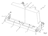
- FIG. 2 shows an embodiment of a clip 2 according to the invention in the collapsed state.
- the clamp 2 consists essentially of a rear clamping element 6 and a front clamping element 7.
- the two clamping elements 6, 7 are connected via guides 9, 10 and can be moved over the guides 9, 10 in the direction of the arrow K back and forth, to either clamp or release the book block B.
- the clamping elements 6, 7 executed at least two parts and form the Operaklemmemia 6 ', 6 "or 7' and 7".
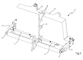
- the Operaklemm institute 6 ', 6 "and 7', 7" pull apart. This will, as in FIG.
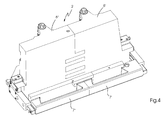
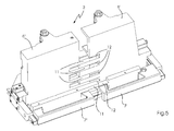
- FIGS. 4 and 5 show an alternative embodiment of a clamp according to the invention 2.
- the Diagramklemm implant 6 ', 6 "and 7', 7" connected to each other via ribs 11, which are guided in complementary recesses 12 of the respective part clamping element.
- the invention is not limited to making the clamps flexible with respect to their extent in the transport direction. It is also possible, alternatively or additionally, to make the ridges flexible in their height via corresponding guides.
Landscapes
- Feeding Of Articles By Means Other Than Belts Or Rollers (AREA)
- Stacking Of Articles And Auxiliary Devices (AREA)
- Folding Of Thin Sheet-Like Materials, Special Discharging Devices, And Others (AREA)
Abstract
Description
- Die Erfindung betrifft eine Klammer, insbesondere für Buchbindemaschinen gemäß dem Oberbegriff von Anspruch 1.
- Derartige Buchbindemaschinen, z.B. Klebebinder, dienen der Herstellung von klebegebundenen Broschuren oder Buchblocks für Festeinbände, wobei die zu einem Buchblock zusammengetragenen Falzbogen und / oder Einzelblätter durch Auftragen eines Klebstoffs auf den zuvor bearbeiteten Blockrücken verbunden werden. Die möglichen Bindeverfahren und die Produktvarianten sind von der Maschinenausrüstung abhängig. Diese besteht im Wesentlichen aus den Funktionseinheiten Buchblocktransportsystem, Buchblockeinführstation, Buchblockrüttelstation, Rückenbearbeitung, Rückenbeleimen, Zwischentrocknung, Seitenbeleimen, Rückenverstärkung, Umschlag anlegen, Umschlag andrücken und Buchblockausfuhr.
- Die
DE 20 2005 007 012 U1 zeigt eine derartige Buchbindemaschine mit einem Buchblocktransportsystem. Das Buchblocktransportsystem besteht aus um Umlenkräder laufenden Fördermitteln und einer Vielzahl von in einem gleichen in gegenseitigen Abstand zueinander daran befestigten Klammern zum Einspannen von Blattstapeln. - Nach dem Stand der Technik kommen als Fördermittel vorzugsweise Rollenketten mit einzeln beweglich ineinander greifenden Gliedern zum Einsatz. Die Ketten dienen dem Vortrieb der Klammern. Geführt werden die Klammern jedoch durch fest mit dem Maschinengestell der Buchbindemaschine verbundene Führungsbahnen. Dazu besitzt eine jede Klammer mehrere Laufrollen, welche auf der Lauffläche der Führungsbahn abrollen.
- Nachteilig an derartigen Buchbindemaschinen ist, dass die Ketten und die Kettenführungen einem sehr hohen Verschleiß unterliegen. Dies erfordert eine stabile Bauweise, d.h. hohe bewegte Massen. Der Antrieb der Klammern durch die Kette bewirkt ein ungleichförmiges Bewegungsprofil der Kette und Schwingungseintrag auf Grund des sogenannten Polygoneffekts. Ebenfalls nachteilig ist, dass die Geschwindigkeiten der Arbeitsstationen an die Geschwindigkeit der Kette mit den Klammen angepasst werden müssen. Damit können keine für den jeweiligen Bearbeitungsprozess idealen Geschwindigkeiten gewählt werden. D.h. die Geschwindigkeiten der Arbeitsstationen können nicht einzeln optimiert werden, sondern sind vielmehr von der Kettengeschwindigkeit abhängig. Diese bestimmt wiederum die Leistung des Klebebinders. Zudem sind, wie bereits erwähnt, die Klammern nicht flexibel, sondern in festem Abstand zueinander angeordnet.
- Aus der
DE 10 2007 032 604 A1 ist es bekannt, die Klammern einzeln bspw. durch Wanderfeldmotoren oder Servomotoren anzutreiben und dadurch eine höhere Flexibilität in der Transportgeschwindigkeit zu erreichen. - Aufgabe der vorliegenden Erfindung ist es, eine Klammer für eine Buchbindemaschine zu schaffen, die unterschiedliche Formate flexibel verarbeiten kann.
- Gelöst wird diese Aufgabe durch eine Klammer mit den kennzeichnenden Merkmalen von Anspruch 1 bzw. ein Verfahren gemäß Anspruch 7 und eine Buchbindemaschine gemäß Anspruch 5.
- Eine erfindungsgemäße Klammer zum Einspannen von Buchblöcken wird vorzugsweise in Buchbindemaschinen zur Erstellung von Druckprodukten, wie Büchern, Zeitschriften oder Broschuren, eingesetzt. Eine derartige Buchbindemaschine weist mehrere einzeln angetriebene Bearbeitungsstationen und ein Transportsystem mit einer Vielzahl von Klammern zum Einspannen und Transportieren von Buchblöcken auf. Die Klammern sind hierbei jeweils einzeln angetrieben auf Führungsbahnen geführt. Hierbei werden die Klammern vorteilhafter Weise durch Wanderfeldmotoren, also Linearmotoren oder Servomotoren angetrieben. Erfindungsgemäß bestehen die Klammen jeweils aus mindestens zwei Teilen, die über Führungen teleskopartig ausziehbar miteinander verbunden sind.
- In einer bevorzugten Ausführungsform bestehen die Führungen aus Rundstäben, auf denen die Klammerteile verschoben werden können.
- Die Rundstäbe sind hierbei an einem Klammerteil befestigt und können in entsprechende Bohrungen des jeweiligen anderen Klammerteils eingreifen. Hierdurch wird auf einfache Art und Weise eine teleskopartige Verschiebung der Klammerteile zueinander ermöglicht. Es ist ebenso möglich, dass beide Klammerteile Rundstäbe aufweisen, die dann in Bohrungen des jeweils anderen Klammerteils eingreifen.
- In einer weiteren bevorzugten Ausführungsform sind die Führungen Rippen, die Teil des jeweiligen Klammerteils sind. Der jeweils andere Klammerteil weist dann entsprechend komplementär geformte Ausnehmungen auf, die die Rippen aufnehmen.
- Klammern der erfindungsgemäßen Art haben den Vorteil, dass sie leicht auf unterschiedliche Rückenlängen der Buchblockform dadurch einzustellen sind, dass die jeweiligen Klammerteile teleskopartig auseinander gezogen oder zusammengeschoben werden können. Damit ergibt sich die Möglichkeit, entsprechend des Formates unterschiedliche Buchblockklammerabstände innerhalb einer Buchbindemaschine, wie beispielsweise eines Klebebinders, zu realisieren, da keine Transportkettenteilungen mehr vorgegeben sind. Aufgrund der Einzelantriebe der Klammern ist es somit möglich, in Abhängigkeit des Formates höhere Verarbeitungsleistungen zu erzielen, denn bei kleineren Formaten können durch die verkleinerten Buchblockklammem und die kleineren Lücken zwischen den Klammern entsprechend der jeweiligen Bearbeitungsstation partiell höhere Leistungen erzielt werden. Alternativ können, je nach zu verarbeitendem Format, unterschiedlich viele Klammern benutzt werden.
- Hinsichtlich weiterer vorteilhafter Ausgestaltungen der Erfindung wird auf die Unteransprüche sowie die Beschreibung eines Ausführungsbeispiels unter Bezugnahme auf die beiliegenden Zeichnungen verwiesen.
- Die Erfindung soll anhand eines Ausführungsbeispiels noch näher erläutert werden. Es zeigen in schematischer Darstellung
- Fig. 1
- die segmentierte Führungsbahn eines Buchtransportsystems
- Fig. 2
- eine Ausführungsform einer erfindungsgemäßen Klammer im zusammengeschobenen Zustand
- Fig. 3
- die Klammer von
Fig.2 im ausgezogenen Zustand - Fig. 4
- eine alternative Ausführungsform einer erfindungsgemäßen Klammer im zusammengeschobenen Zustand.
- Fig. 5
- die Klammer von
Fig. 4 im ausgezogenen Zustand - In
Fig. 1 ist das Buchblocktransportsystem 1 eines Klebebinders näher dargestellt: Dieses besteht aus Klammern 2, die den Buchblock B einklemmen und auf einer Führungsbahn 4 geführt werden. Die Klammern 2 werden durch Wanderfeldmotoren angetrieben. Die Führungsbahn 4 besteht aus einer Vielzahl von Segmenten 5, welche hier nur schematisch dargestellt sind. Selbstverständlich muss die Segmentierung wesentlich feiner ausgestaltet sein. Durch das in den Segmenten 5 der Führungsbahn 4 erzeugte Wanderfeld werden die Klammern 2 in Transportrichtung T bewegt. Die Einrichtungen zur Erzeugung des Wanderfelds liegen im Ermessen des Fachmanns und sind inFig. 1 nicht dargestellt. -
Figur 2 zeigt eine Ausführungsform einer erfindungsgemäßen Klammer 2 im zusammengeschobenen Zustand. Die Klammer 2 besteht im Wesentlichen aus einem hinteren Klemmelement 6 und einem vorderen Klemmelement 7. Die beiden Klemmelemente 6, 7 sind über Führungen 9, 10 miteinander verbunden und können über die Führungen 9, 10 in Richtung des Pfeils K hin und her bewegt werden, um den Buchblock B entweder zu klemmen oder freizugeben. Wie ausFigur 2 zu erkennen ist, sind die Klemmelemente 6, 7 zumindest zweigeteilt ausgeführt und bilden die Teilklemmelemente 6', 6" bzw. 7' und 7". Um nun auch Buchblocks sicher klemmen zu können, die ein größeres Format haben, ist es möglich, die Teilklemmelemente 6', 6" und 7', 7" auseinanderzuziehen. Dies wird, wie inFigur 3 dargestellt, ermöglicht durch Führungen 8, die die jeweiligen Teilklemmelemente 6', 6", 7', 7" miteinander verbinden. Die Führungen können hierbei, wie inFigur 3 gezeigt, aus Rundstäben bestehen, die an einem Teilklemmelement befestigt sind und in entsprechenden Bohrungen des anderen Teilklemmelements geführt werden. - Die
Figuren 4 und5 zeigen eine alternative Ausführungsform einer erfindungsgemäßen Klammer 2. Bei dieser Ausführungsform sind die Teilklemmelemente 6', 6" und 7', 7" über Rippen 11 miteinander verbunden, die in komplementären Ausnehmungen 12 des jeweiligen Teilklemmelementes geführt werden. - Die Erfindung ist nicht darauf beschränkt, die Klammern flexibel hinsichtlich ihrer Ausdehnung in Transportrichtung zu gestalten. Es ist ebenso möglich, alternativ oder zusätzlich die Klammen auch in ihrer Höhe über entsprechende Führungen flexibel zu gestalten.
-
- 1
- Buchblocktransportsystem
- 2
- Klammer
- 4
- Führungsbahn
- 5
- Segment der Führungsbahn
- 6
- Klemmelement
- 6', 6"
- Teilklemmelement
- 7
- Klemmelement
- 7', 7"
- Teilklemmelement
- 8
- Führung
- 9
- Führung
- 10
- Führung
- 11
- Rippe
- 12
- komplementäre Ausnehmung
- B
- Buchblock
- T
- Transportrichtung
- K
- Bewegungsrichtung
Claims (7)
- Klammer zum Einspannen von Buchblöcken,
dadurch gekennzeichnet,
dass die Klammern (2) mindestens ein vorderes (7) und ein hinteres Klemmelement (6) aufweisen, die jeweils mindestens zwei Teilklemmelemente (6', 6", 7', 7")
aufweisen, die über Führungen (8, 11) teleskopartig ausziehbar miteinander verbunden sind. - Klammer nach Anspruch 1,
dadurch gekennzeichnet,
dass an dem einen Teilklemmelement Rundstäbe (8) befestigt sind und dass das andere Teilklemmelement entsprechende Bohrungen aufweist. - Klammer nach Anspruch 1,
dadurch gekennzeichnet,
dass die Teilklemmelemente Rippen (11) aufweisen, die komplementär zu Ausnehmungen (12) im jeweils anderen Teilklemmelement geformt sind. - Klammer nach einem der Ansprüche 1 bis 3"
dadurch gekennzeichnet,
dass jede Klammer (2) mit einem eigenen Antrieb versehen ist und die Buchblöcke auf einer Umlaufbahn durch verschiedene Bearbeitungsstationen führt. - Buchbindemaschine zur Erstellung von Druckprodukten, wie Bücher, Zeitschriften, Broschuren etc., mit mehreren Bearbeitungsstationen und einem Buchblocktransportsystem mit einer Vielzahl von Klammern gemäß einem der Ansprüche 1 bis 4.
- Buchbindemaschine nach Anspruch 4,
dadurch gekennzeichnet,
dass die einzelnen Bearbeitungsstationen jeweils separate Antriebe aufweisen. - Verfahren zur Einstellung von Klammern (2) auf das jeweilige Format von einzuklemmenden Buchblocks,
dadurch gekennzeichnet,
dass die jeweiligen Teilklemmelemente einer jeden Klammer (2) auseinandergezogen oder zusammengeschoben werden und so auf das entsprechende Produktformat eingestellt werden.
Applications Claiming Priority (1)
| Application Number | Priority Date | Filing Date | Title |
|---|---|---|---|
| DE102008047192A DE102008047192A1 (de) | 2008-09-15 | 2008-09-15 | Klebebinder |
Publications (3)
| Publication Number | Publication Date |
|---|---|
| EP2163395A2 true EP2163395A2 (de) | 2010-03-17 |
| EP2163395A3 EP2163395A3 (de) | 2013-08-21 |
| EP2163395B1 EP2163395B1 (de) | 2017-10-25 |
Family
ID=41413084
Family Applications (1)
| Application Number | Title | Priority Date | Filing Date |
|---|---|---|---|
| EP09169463.8A Not-in-force EP2163395B1 (de) | 2008-09-15 | 2009-09-04 | Klammer für Buchblocktransportsystem |
Country Status (2)
| Country | Link |
|---|---|
| EP (1) | EP2163395B1 (de) |
| DE (1) | DE102008047192A1 (de) |
Families Citing this family (1)
| Publication number | Priority date | Publication date | Assignee | Title |
|---|---|---|---|---|
| DE102012023370A1 (de) * | 2012-11-29 | 2014-06-05 | Heidelberger Druckmaschinen Ag | Klebebinder mit Kettenantrieb pro Klammer |
Citations (2)
| Publication number | Priority date | Publication date | Assignee | Title |
|---|---|---|---|---|
| DE202005007012U1 (de) | 2005-05-02 | 2005-08-04 | Kolbus Gmbh & Co. Kg | Buchbindemaschine |
| DE102007032604A1 (de) | 2006-07-26 | 2008-01-31 | Heidelberger Druckmaschinen Ag | Klebebinder |
Family Cites Families (3)
| Publication number | Priority date | Publication date | Assignee | Title |
|---|---|---|---|---|
| GB291650A (en) * | 1927-08-29 | 1928-06-07 | Wilhelm Friedrichs | Improvements in apparatus for manually applying book covers |
| DE4012084A1 (de) * | 1990-04-14 | 1991-10-17 | Kolbus Gmbh & Co Kg | Buchblocktransportkanal |
| DE102006012084B4 (de) * | 2006-03-14 | 2018-02-08 | Müller Martini Holding AG | Vorrichtung und Verfahren zum Anpressen eines Umschlages an einen bewegten Bedruckstoffblock |
-
2008
- 2008-09-15 DE DE102008047192A patent/DE102008047192A1/de not_active Withdrawn
-
2009
- 2009-09-04 EP EP09169463.8A patent/EP2163395B1/de not_active Not-in-force
Patent Citations (2)
| Publication number | Priority date | Publication date | Assignee | Title |
|---|---|---|---|---|
| DE202005007012U1 (de) | 2005-05-02 | 2005-08-04 | Kolbus Gmbh & Co. Kg | Buchbindemaschine |
| DE102007032604A1 (de) | 2006-07-26 | 2008-01-31 | Heidelberger Druckmaschinen Ag | Klebebinder |
Also Published As
| Publication number | Publication date |
|---|---|
| EP2163395A3 (de) | 2013-08-21 |
| EP2163395B1 (de) | 2017-10-25 |
| DE102008047192A1 (de) | 2010-04-15 |
Similar Documents
| Publication | Publication Date | Title |
|---|---|---|
| DE102007032604B4 (de) | Klebebinder | |
| EP2738011B1 (de) | Klebebinder mit Kettenantrieb pro Klammer | |
| EP2049344B1 (de) | Buchbindemaschine | |
| EP1690696B1 (de) | Verfahren sowie Vorrichtung zum Abpressen von Druckerzeugnissen | |
| EP2377688B1 (de) | Vorrichtung zur Herstellung von klebegebundenen Produkten | |
| EP2923852B1 (de) | Vorrichtung zum formen von buchdecken | |
| DE202005007012U1 (de) | Buchbindemaschine | |
| DE102007060569A1 (de) | Vorrichtung zum Zuführen von Buchblocks | |
| EP2397339A2 (de) | Verfahren und Vorrichtung zur Herstellung von Buchdecken | |
| EP2711194B1 (de) | Buchbindemachine | |
| DE102008060073A1 (de) | Rillung von Umschlägen in einem Klebebinder | |
| DE102006012084A1 (de) | Vorrichtung und Verfahren zum Anpressen eines Umschlages an einen bewegten Bedruckstoffblock | |
| EP2517892A1 (de) | Vorrichtung und Verfahren zur Herstellung von gebundenen, einen Fälzelstreifen oder einen Umschlag aufweisenden Buchblocks | |
| EP3406456B1 (de) | Klebebinder | |
| EP2163395B1 (de) | Klammer für Buchblocktransportsystem | |
| DE10039908A1 (de) | Verfahren und Vorrichtung zum maschinellen Heften von mehrteiligen Druckereiprodukten mittels Drahtklammern | |
| EP2422992A1 (de) | Verfahren und Vorrichtung zum Einhängen eines Buchblocks in eine Buchdecke | |
| EP3290223B1 (de) | Vorrichtung und verfahren für die ausrichtung eines aus einzelblättern und/oder signaturen bestehenden buchblocks | |
| EP0976672A2 (de) | Transportvorrichtung | |
| DE102014002506A1 (de) | Klebebinderklammer | |
| DE102009045319B4 (de) | Formateinstellvorrichtung | |
| EP2316767A1 (de) | Verfahren und Vorrichtung zum Herstellen von Stapeln aus Druckprodukten | |
| EP2191977A2 (de) | Vorrichtung zum Anlegen eines Umschlags | |
| EP2711192B1 (de) | Vorrichtung zum Anlegen eines Umschlags | |
| DE102008013223A1 (de) | Vorrichtung zum Heften von Druckprodukten, insbesondere von Broschüren, gefalzten bzw. ungefalzten Bogen, Karten oder dergleichen |
Legal Events
| Date | Code | Title | Description |
|---|---|---|---|
| PUAI | Public reference made under article 153(3) epc to a published international application that has entered the european phase |
Free format text: ORIGINAL CODE: 0009012 |
|
| AK | Designated contracting states |
Kind code of ref document: A2 Designated state(s): AT BE BG CH CY CZ DE DK EE ES FI FR GB GR HR HU IE IS IT LI LT LU LV MC MK MT NL NO PL PT RO SE SI SK SM TR |
|
| PUAL | Search report despatched |
Free format text: ORIGINAL CODE: 0009013 |
|
| AK | Designated contracting states |
Kind code of ref document: A3 Designated state(s): AT BE BG CH CY CZ DE DK EE ES FI FR GB GR HR HU IE IS IT LI LT LU LV MC MK MT NL NO PL PT RO SE SI SK SM TR |
|
| RIC1 | Information provided on ipc code assigned before grant |
Ipc: B42C 11/00 20060101ALI20130715BHEP Ipc: B42C 19/08 20060101AFI20130715BHEP Ipc: B65H 29/04 20060101ALI20130715BHEP |
|
| 17P | Request for examination filed |
Effective date: 20140221 |
|
| RBV | Designated contracting states (corrected) |
Designated state(s): AT BE BG CH CY CZ DE DK EE ES FI FR GB GR HR HU IE IS IT LI LT LU LV MC MK MT NL NO PL PT RO SE SI SK SM TR |
|
| RAP1 | Party data changed (applicant data changed or rights of an application transferred) |
Owner name: MUELLER MARTINI HOLDING AG |
|
| GRAP | Despatch of communication of intention to grant a patent |
Free format text: ORIGINAL CODE: EPIDOSNIGR1 |
|
| INTG | Intention to grant announced |
Effective date: 20170413 |
|
| GRAS | Grant fee paid |
Free format text: ORIGINAL CODE: EPIDOSNIGR3 |
|
| GRAJ | Information related to disapproval of communication of intention to grant by the applicant or resumption of examination proceedings by the epo deleted |
Free format text: ORIGINAL CODE: EPIDOSDIGR1 |
|
| GRAL | Information related to payment of fee for publishing/printing deleted |
Free format text: ORIGINAL CODE: EPIDOSDIGR3 |
|
| GRAR | Information related to intention to grant a patent recorded |
Free format text: ORIGINAL CODE: EPIDOSNIGR71 |
|
| INTC | Intention to grant announced (deleted) | ||
| INTG | Intention to grant announced |
Effective date: 20170725 |
|
| GRAA | (expected) grant |
Free format text: ORIGINAL CODE: 0009210 |
|
| AK | Designated contracting states |
Kind code of ref document: B1 Designated state(s): AT BE BG CH CY CZ DE DK EE ES FI FR GB GR HR HU IE IS IT LI LT LU LV MC MK MT NL NO PL PT RO SE SI SK SM TR |
|
| REG | Reference to a national code |
Ref country code: GB Ref legal event code: FG4D Free format text: NOT ENGLISH |
|
| REG | Reference to a national code |
Ref country code: CH Ref legal event code: EP |
|
| REG | Reference to a national code |
Ref country code: AT Ref legal event code: REF Ref document number: 939550 Country of ref document: AT Kind code of ref document: T Effective date: 20171115 |
|
| REG | Reference to a national code |
Ref country code: IE Ref legal event code: FG4D Free format text: LANGUAGE OF EP DOCUMENT: GERMAN |
|
| REG | Reference to a national code |
Ref country code: DE Ref legal event code: R096 Ref document number: 502009014470 Country of ref document: DE |
|
| REG | Reference to a national code |
Ref country code: NL Ref legal event code: MP Effective date: 20171025 |
|
| REG | Reference to a national code |
Ref country code: LT Ref legal event code: MG4D |
|
| PG25 | Lapsed in a contracting state [announced via postgrant information from national office to epo] |
Ref country code: NL Free format text: LAPSE BECAUSE OF FAILURE TO SUBMIT A TRANSLATION OF THE DESCRIPTION OR TO PAY THE FEE WITHIN THE PRESCRIBED TIME-LIMIT Effective date: 20171025 |
|
| PG25 | Lapsed in a contracting state [announced via postgrant information from national office to epo] |
Ref country code: SE Free format text: LAPSE BECAUSE OF FAILURE TO SUBMIT A TRANSLATION OF THE DESCRIPTION OR TO PAY THE FEE WITHIN THE PRESCRIBED TIME-LIMIT Effective date: 20171025 Ref country code: NO Free format text: LAPSE BECAUSE OF FAILURE TO SUBMIT A TRANSLATION OF THE DESCRIPTION OR TO PAY THE FEE WITHIN THE PRESCRIBED TIME-LIMIT Effective date: 20180125 Ref country code: FI Free format text: LAPSE BECAUSE OF FAILURE TO SUBMIT A TRANSLATION OF THE DESCRIPTION OR TO PAY THE FEE WITHIN THE PRESCRIBED TIME-LIMIT Effective date: 20171025 Ref country code: LT Free format text: LAPSE BECAUSE OF FAILURE TO SUBMIT A TRANSLATION OF THE DESCRIPTION OR TO PAY THE FEE WITHIN THE PRESCRIBED TIME-LIMIT Effective date: 20171025 Ref country code: ES Free format text: LAPSE BECAUSE OF FAILURE TO SUBMIT A TRANSLATION OF THE DESCRIPTION OR TO PAY THE FEE WITHIN THE PRESCRIBED TIME-LIMIT Effective date: 20171025 |
|
| PG25 | Lapsed in a contracting state [announced via postgrant information from national office to epo] |
Ref country code: BG Free format text: LAPSE BECAUSE OF FAILURE TO SUBMIT A TRANSLATION OF THE DESCRIPTION OR TO PAY THE FEE WITHIN THE PRESCRIBED TIME-LIMIT Effective date: 20180125 Ref country code: IS Free format text: LAPSE BECAUSE OF FAILURE TO SUBMIT A TRANSLATION OF THE DESCRIPTION OR TO PAY THE FEE WITHIN THE PRESCRIBED TIME-LIMIT Effective date: 20180225 Ref country code: GR Free format text: LAPSE BECAUSE OF FAILURE TO SUBMIT A TRANSLATION OF THE DESCRIPTION OR TO PAY THE FEE WITHIN THE PRESCRIBED TIME-LIMIT Effective date: 20180126 Ref country code: HR Free format text: LAPSE BECAUSE OF FAILURE TO SUBMIT A TRANSLATION OF THE DESCRIPTION OR TO PAY THE FEE WITHIN THE PRESCRIBED TIME-LIMIT Effective date: 20171025 Ref country code: LV Free format text: LAPSE BECAUSE OF FAILURE TO SUBMIT A TRANSLATION OF THE DESCRIPTION OR TO PAY THE FEE WITHIN THE PRESCRIBED TIME-LIMIT Effective date: 20171025 |
|
| REG | Reference to a national code |
Ref country code: DE Ref legal event code: R097 Ref document number: 502009014470 Country of ref document: DE |
|
| PG25 | Lapsed in a contracting state [announced via postgrant information from national office to epo] |
Ref country code: CY Free format text: LAPSE BECAUSE OF FAILURE TO SUBMIT A TRANSLATION OF THE DESCRIPTION OR TO PAY THE FEE WITHIN THE PRESCRIBED TIME-LIMIT Effective date: 20171025 Ref country code: EE Free format text: LAPSE BECAUSE OF FAILURE TO SUBMIT A TRANSLATION OF THE DESCRIPTION OR TO PAY THE FEE WITHIN THE PRESCRIBED TIME-LIMIT Effective date: 20171025 Ref country code: DK Free format text: LAPSE BECAUSE OF FAILURE TO SUBMIT A TRANSLATION OF THE DESCRIPTION OR TO PAY THE FEE WITHIN THE PRESCRIBED TIME-LIMIT Effective date: 20171025 Ref country code: SK Free format text: LAPSE BECAUSE OF FAILURE TO SUBMIT A TRANSLATION OF THE DESCRIPTION OR TO PAY THE FEE WITHIN THE PRESCRIBED TIME-LIMIT Effective date: 20171025 Ref country code: CZ Free format text: LAPSE BECAUSE OF FAILURE TO SUBMIT A TRANSLATION OF THE DESCRIPTION OR TO PAY THE FEE WITHIN THE PRESCRIBED TIME-LIMIT Effective date: 20171025 |
|
| PG25 | Lapsed in a contracting state [announced via postgrant information from national office to epo] |
Ref country code: SM Free format text: LAPSE BECAUSE OF FAILURE TO SUBMIT A TRANSLATION OF THE DESCRIPTION OR TO PAY THE FEE WITHIN THE PRESCRIBED TIME-LIMIT Effective date: 20171025 Ref country code: PL Free format text: LAPSE BECAUSE OF FAILURE TO SUBMIT A TRANSLATION OF THE DESCRIPTION OR TO PAY THE FEE WITHIN THE PRESCRIBED TIME-LIMIT Effective date: 20171025 Ref country code: IT Free format text: LAPSE BECAUSE OF FAILURE TO SUBMIT A TRANSLATION OF THE DESCRIPTION OR TO PAY THE FEE WITHIN THE PRESCRIBED TIME-LIMIT Effective date: 20171025 Ref country code: RO Free format text: LAPSE BECAUSE OF FAILURE TO SUBMIT A TRANSLATION OF THE DESCRIPTION OR TO PAY THE FEE WITHIN THE PRESCRIBED TIME-LIMIT Effective date: 20171025 |
|
| PLBE | No opposition filed within time limit |
Free format text: ORIGINAL CODE: 0009261 |
|
| STAA | Information on the status of an ep patent application or granted ep patent |
Free format text: STATUS: NO OPPOSITION FILED WITHIN TIME LIMIT |
|
| PG25 | Lapsed in a contracting state [announced via postgrant information from national office to epo] |
Ref country code: MT Free format text: LAPSE BECAUSE OF FAILURE TO SUBMIT A TRANSLATION OF THE DESCRIPTION OR TO PAY THE FEE WITHIN THE PRESCRIBED TIME-LIMIT Effective date: 20171025 |
|
| 26N | No opposition filed |
Effective date: 20180726 |
|
| PG25 | Lapsed in a contracting state [announced via postgrant information from national office to epo] |
Ref country code: SI Free format text: LAPSE BECAUSE OF FAILURE TO SUBMIT A TRANSLATION OF THE DESCRIPTION OR TO PAY THE FEE WITHIN THE PRESCRIBED TIME-LIMIT Effective date: 20171025 |
|
| PG25 | Lapsed in a contracting state [announced via postgrant information from national office to epo] |
Ref country code: MC Free format text: LAPSE BECAUSE OF FAILURE TO SUBMIT A TRANSLATION OF THE DESCRIPTION OR TO PAY THE FEE WITHIN THE PRESCRIBED TIME-LIMIT Effective date: 20171025 |
|
| REG | Reference to a national code |
Ref country code: CH Ref legal event code: PL |
|
| GBPC | Gb: european patent ceased through non-payment of renewal fee |
Effective date: 20180904 |
|
| REG | Reference to a national code |
Ref country code: BE Ref legal event code: MM Effective date: 20180930 |
|
| REG | Reference to a national code |
Ref country code: IE Ref legal event code: MM4A |
|
| PG25 | Lapsed in a contracting state [announced via postgrant information from national office to epo] |
Ref country code: LU Free format text: LAPSE BECAUSE OF NON-PAYMENT OF DUE FEES Effective date: 20180904 |
|
| PG25 | Lapsed in a contracting state [announced via postgrant information from national office to epo] |
Ref country code: IE Free format text: LAPSE BECAUSE OF NON-PAYMENT OF DUE FEES Effective date: 20180904 |
|
| PG25 | Lapsed in a contracting state [announced via postgrant information from national office to epo] |
Ref country code: BE Free format text: LAPSE BECAUSE OF NON-PAYMENT OF DUE FEES Effective date: 20180930 Ref country code: CH Free format text: LAPSE BECAUSE OF NON-PAYMENT OF DUE FEES Effective date: 20180930 Ref country code: LI Free format text: LAPSE BECAUSE OF NON-PAYMENT OF DUE FEES Effective date: 20180930 Ref country code: FR Free format text: LAPSE BECAUSE OF NON-PAYMENT OF DUE FEES Effective date: 20180930 |
|
| PG25 | Lapsed in a contracting state [announced via postgrant information from national office to epo] |
Ref country code: GB Free format text: LAPSE BECAUSE OF NON-PAYMENT OF DUE FEES Effective date: 20180904 |
|
| REG | Reference to a national code |
Ref country code: AT Ref legal event code: MM01 Ref document number: 939550 Country of ref document: AT Kind code of ref document: T Effective date: 20180904 |
|
| PG25 | Lapsed in a contracting state [announced via postgrant information from national office to epo] |
Ref country code: AT Free format text: LAPSE BECAUSE OF NON-PAYMENT OF DUE FEES Effective date: 20180904 |
|
| PG25 | Lapsed in a contracting state [announced via postgrant information from national office to epo] |
Ref country code: TR Free format text: LAPSE BECAUSE OF FAILURE TO SUBMIT A TRANSLATION OF THE DESCRIPTION OR TO PAY THE FEE WITHIN THE PRESCRIBED TIME-LIMIT Effective date: 20171025 |
|
| PG25 | Lapsed in a contracting state [announced via postgrant information from national office to epo] |
Ref country code: HU Free format text: LAPSE BECAUSE OF FAILURE TO SUBMIT A TRANSLATION OF THE DESCRIPTION OR TO PAY THE FEE WITHIN THE PRESCRIBED TIME-LIMIT; INVALID AB INITIO Effective date: 20090904 Ref country code: PT Free format text: LAPSE BECAUSE OF FAILURE TO SUBMIT A TRANSLATION OF THE DESCRIPTION OR TO PAY THE FEE WITHIN THE PRESCRIBED TIME-LIMIT Effective date: 20171025 |
|
| PG25 | Lapsed in a contracting state [announced via postgrant information from national office to epo] |
Ref country code: MK Free format text: LAPSE BECAUSE OF NON-PAYMENT OF DUE FEES Effective date: 20171025 |
|
| PGFP | Annual fee paid to national office [announced via postgrant information from national office to epo] |
Ref country code: DE Payment date: 20220928 Year of fee payment: 14 |
|
| REG | Reference to a national code |
Ref country code: DE Ref legal event code: R119 Ref document number: 502009014470 Country of ref document: DE |
|
| PG25 | Lapsed in a contracting state [announced via postgrant information from national office to epo] |
Ref country code: DE Free format text: LAPSE BECAUSE OF NON-PAYMENT OF DUE FEES Effective date: 20240403 |