EP2162892B1 - Herstellungsverfahren für einen stössel und derartiger stössel - Google Patents
Herstellungsverfahren für einen stössel und derartiger stössel Download PDFInfo
- Publication number
- EP2162892B1 EP2162892B1 EP20070802875 EP07802875A EP2162892B1 EP 2162892 B1 EP2162892 B1 EP 2162892B1 EP 20070802875 EP20070802875 EP 20070802875 EP 07802875 A EP07802875 A EP 07802875A EP 2162892 B1 EP2162892 B1 EP 2162892B1
- Authority
- EP
- European Patent Office
- Prior art keywords
- plunger
- central region
- injection
- switching device
- detection device
- Prior art date
- Legal status (The legal status is an assumption and is not a legal conclusion. Google has not performed a legal analysis and makes no representation as to the accuracy of the status listed.)
- Not-in-force
Links
- 238000004519 manufacturing process Methods 0.000 title claims description 11
- 239000000463 material Substances 0.000 claims description 33
- 239000004033 plastic Substances 0.000 claims description 6
- 238000001746 injection moulding Methods 0.000 claims description 5
- 238000002347 injection Methods 0.000 claims description 3
- 239000007924 injection Substances 0.000 claims description 3
- 230000010354 integration Effects 0.000 claims description 2
- 238000001514 detection method Methods 0.000 description 25
- 230000005415 magnetization Effects 0.000 description 5
- 238000010586 diagram Methods 0.000 description 1
- 238000003780 insertion Methods 0.000 description 1
- 230000037431 insertion Effects 0.000 description 1
- 239000000696 magnetic material Substances 0.000 description 1
- 239000002245 particle Substances 0.000 description 1
- 229920001169 thermoplastic Polymers 0.000 description 1
- 239000004416 thermosoftening plastic Substances 0.000 description 1
- 229910000859 α-Fe Inorganic materials 0.000 description 1
Images

Classifications
-
- H—ELECTRICITY
- H01—ELECTRIC ELEMENTS
- H01H—ELECTRIC SWITCHES; RELAYS; SELECTORS; EMERGENCY PROTECTIVE DEVICES
- H01H11/00—Apparatus or processes specially adapted for the manufacture of electric switches
- H01H11/0062—Testing or measuring non-electrical properties of switches, e.g. contact velocity
-
- H—ELECTRICITY
- H01—ELECTRIC ELEMENTS
- H01H—ELECTRIC SWITCHES; RELAYS; SELECTORS; EMERGENCY PROTECTIVE DEVICES
- H01H9/00—Details of switching devices, not covered by groups H01H1/00 - H01H7/00
- H01H9/16—Indicators for switching condition, e.g. "on" or "off"
-
- H—ELECTRICITY
- H01—ELECTRIC ELEMENTS
- H01H—ELECTRIC SWITCHES; RELAYS; SELECTORS; EMERGENCY PROTECTIVE DEVICES
- H01H71/00—Details of the protective switches or relays covered by groups H01H73/00 - H01H83/00
- H01H71/04—Means for indicating condition of the switching device
- H01H2071/048—Means for indicating condition of the switching device containing non-mechanical switch position sensor, e.g. HALL sensor
-
- H—ELECTRICITY
- H01—ELECTRIC ELEMENTS
- H01H—ELECTRIC SWITCHES; RELAYS; SELECTORS; EMERGENCY PROTECTIVE DEVICES
- H01H50/00—Details of electromagnetic relays
- H01H50/08—Indicators; Distinguishing marks
-
- Y—GENERAL TAGGING OF NEW TECHNOLOGICAL DEVELOPMENTS; GENERAL TAGGING OF CROSS-SECTIONAL TECHNOLOGIES SPANNING OVER SEVERAL SECTIONS OF THE IPC; TECHNICAL SUBJECTS COVERED BY FORMER USPC CROSS-REFERENCE ART COLLECTIONS [XRACs] AND DIGESTS
- Y10—TECHNICAL SUBJECTS COVERED BY FORMER USPC
- Y10T—TECHNICAL SUBJECTS COVERED BY FORMER US CLASSIFICATION
- Y10T29/00—Metal working
- Y10T29/49—Method of mechanical manufacture
- Y10T29/49002—Electrical device making
- Y10T29/49105—Switch making
-
- Y—GENERAL TAGGING OF NEW TECHNOLOGICAL DEVELOPMENTS; GENERAL TAGGING OF CROSS-SECTIONAL TECHNOLOGIES SPANNING OVER SEVERAL SECTIONS OF THE IPC; TECHNICAL SUBJECTS COVERED BY FORMER USPC CROSS-REFERENCE ART COLLECTIONS [XRACs] AND DIGESTS
- Y10—TECHNICAL SUBJECTS COVERED BY FORMER USPC
- Y10T—TECHNICAL SUBJECTS COVERED BY FORMER US CLASSIFICATION
- Y10T29/00—Metal working
- Y10T29/49—Method of mechanical manufacture
- Y10T29/49002—Electrical device making
- Y10T29/49117—Conductor or circuit manufacturing
- Y10T29/49204—Contact or terminal manufacturing
- Y10T29/49208—Contact or terminal manufacturing by assembling plural parts
- Y10T29/49222—Contact or terminal manufacturing by assembling plural parts forming array of contacts or terminals
-
- Y—GENERAL TAGGING OF NEW TECHNOLOGICAL DEVELOPMENTS; GENERAL TAGGING OF CROSS-SECTIONAL TECHNOLOGIES SPANNING OVER SEVERAL SECTIONS OF THE IPC; TECHNICAL SUBJECTS COVERED BY FORMER USPC CROSS-REFERENCE ART COLLECTIONS [XRACs] AND DIGESTS
- Y10—TECHNICAL SUBJECTS COVERED BY FORMER USPC
- Y10T—TECHNICAL SUBJECTS COVERED BY FORMER US CLASSIFICATION
- Y10T428/00—Stock material or miscellaneous articles
- Y10T428/31504—Composite [nonstructural laminate]
Definitions
- the present invention relates to a manufacturing method for a ram having, viewed in a longitudinal direction, a central region and two outer regions bordering the central region, the outer regions of the ram being injection-molded from a non-magnetizable material.
- the present invention further relates to such a plunger.
- Tappets are used inter alia in electromagnetic switching devices and the like.
- the plunger is movably mounted in a housing of the switching device. It is movable between two mechanical end positions, wherein the end positions of the plunger correspond to the switching state of the switching device.
- the contact bridges (or comparable switching elements) of the switching device can be actuated.
- switching devices - especially in contactors - it is necessary in a variety of applications, the actual switching state of the switching device - in contrast, if necessary, to a driving state of the switching device - to capture in order to evaluate it elsewhere.
- the object of the present invention is to provide opportunities, based on which a plunger whose switching position is detected without contact, can be produced in a simple manner.
- the object is achieved by a manufacturing method having the features of claim 1 and a plunger having the features of claim 6.
- the outer regions of the plunger are further injection molded from a non-magnetizable material.
- a magnetizable material is integrated into the plunger.
- a portion of the central region is impressed with a defined magnetization after integrating the magnetizable material into the plunger.
- an injection-moldable material can be used as the magnetizable material.
- the plunger in this case, including the magnetizable material, can be produced by a two-component injection molding process.
- the injection-moldable magnetizable material may in particular be a magnetizable plastic.
- ferrite particles may be added to the plastic.
- the section is identical to the middle section.
- the portion extends only over part of the central area.
- An electromagnetic switching device 1 is designed as a contactor. It has a coil 2, which can be acted upon by a switching current IS. When the switching current IS is applied to the coil 2, it attracts an armature 3. This is in FIG. 1 indicated by an arrow A. If the switching current IS interrupted, the armature 3 moves away from the coil 2 due to a restoring spring force.
- a plunger 4 is connected. Therefore, together with the armature 3, the plunger 4 is attracted by the coil 2. Due to the movement of the plunger 4 (at least) a load contact 5 is closed, so that a load current IL can flow. Conversely, when interrupting the switching current IS of the load contact 5 is opened again.
- the electromagnetic switching device 1 has a plurality of load contacts 5, for example, three, four or five load contacts 5.
- the representation of only a single load contact 5 in FIG. 1 only serves for better clarity.
- the electromagnetic switching device 1 could be designed, for example, as a circuit breaker.
- the switching current IS is identical to the load current IL.
- the coil 2 attracts the armature 3 when the load current IL becomes too large. Due to the tightening of the armature 3, a switching mechanism is released, the plunger. 4 moved to a position in which the load contact 5 remains open.
- the electromagnetic switching device 1 Regardless of the specific embodiment of the electromagnetic switching device 1, the electromagnetic switching device 1, a housing 6, which surrounds the other above-mentioned elements 2 to 5 of the electromagnetic switching device 1. Also, the position of the plunger 4 independently of the specific configuration of the electromagnetic switching device 1 corresponds to the switching state of the load contact 5 and thus the switching state of the electromagnetic switching device. 1
- a detection device 7 In order to detect the switching state of the electromagnetic switching device 1, a detection device 7 is present.
- the detection device 7, which will be explained in more detail below, may be a component of the electromagnetic switching device 1. According to FIG. 1 However, it is designed as a top-mounted device for placement on the electromagnetic switching device 1. According to FIG. 1 Therefore, the detection device 7, a housing 8, which is different from the housing 6 of the electromagnetic switching device 1. Furthermore, the detection device 7 has a plunger 9, which is different from the plunger 4 of the electromagnetic switching device 1.
- the housing 8 of the detection device 7 on the housing 6 of the electromagnetic switching device 1 can be fixed.
- FIG. 1 This is indicated by latching hooks 10, which are arranged on the housing 8 of the detection device 7 and cooperate with latching recesses 11, which are arranged on the housing 6 of the electromagnetic switching device 1.
- the fixation of the detection device 7 on the electromagnetic switching device 1 need not be done by means of a latching connection. It may alternatively or additionally be fixed in other ways, for example by means of screw connections.
- the plunger 9 of the detection device 7 is movably mounted in the housing 8 of the detection device 7.
- the plunger 9 of the detection device 7 is connectable to the plunger 4 of the electromagnetic switching device 1.
- latching hooks 12 for example, which cooperate with latching recesses 13 which are arranged on the plunger 4 of the electromagnetic switching device 1.
- another type of connection is possible. It is crucial that the plunger 9 of the detection device 7 moves together with the plunger 4 of the electromagnetic switching device 1.
- the structure corresponds to the well-known from the prior art structure.
- the plunger 9 of the detection device 7 is movable between two mechanical end positions. Due to the connection of the plunger 9 of the detection device 7 with the plunger 4 of the electromagnetic switching device 1, the end positions of the plunger 9 of the detection device 7 correspond to the switching state of the electromagnetic switching device. 1
- a sensor device 14 is arranged in the housing 8 of the detection device 7. It can be detected by the sensor device 14 in which of the end positions the plunger 9 of the detection device 7 is located. From the sensor device 14, an electrical signal E can be emitted, which corresponds to the detected end position.
- the sensor device 14 is in this case designed such that the position of the plunger 9 of the detection device 7 can be detected by it without touching the plunger 9 of the detection device 7.
- the sensor device 14 can be realized, for example, as a Hall sensor.
- the plunger 9 has seen in a longitudinal direction x a central region 15 and two adjacent to the central region 15 outer regions 16, 17.
- the outer areas 16, 17 exist made of a non-magnetizable, injection-moldable material.
- the material of which the outer regions 16, 17 are made may in particular be a plastic, for example a thermoplastic or a duroplastic.
- a magnetic material is integrated in the middle region 15. At least a portion 18, 19 of the central region 15 is a defined magnetization impressed.
- the central region 15 consists of an injection-moldable magnetizable material.
- the plunger 9 including the magnetizable material constituting the center portion 15 is injection-molded by a two-component injection molding method.
- the injection-moldable magnetizable material is preferably a magnetizable plastic.
- the magnetizable material is otherwise integrated in the central region 15.
- the central region 15 is made, for example, of the same material as the outer regions 16, 17, but in addition the magnetizable material is introduced into the middle region 15.
- the at least one section 18, 19 should be arranged at a predetermined location relative to the longitudinal direction x.
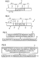
- the at least one section 18, 19 of one of the ends 20, 21 of the plunger 9 should have a defined distance a. If it is possible to maintain lengths 115, 116 and 117 of the central region 15 and the outer regions 16, 17 exactly enough in the manufacturing process, it is possible that the at least one section 18, 19 is identical to the central region 15. This embodiment is in FIG. 3 shown. Alternatively, it is possible for the at least one section 18, 19 to extend over only a part of the middle region 15, that is to say at least one remaining region 22 of the central region 15 remains, which has no magnetization impressed. This embodiment is in FIG. 4 shown.
- FIG. 5 shows the principle according to the invention
- FIG. 6 a preferred embodiment of this principle.
- a step S1 the central region 15 and the outer regions 16, 17 of the tappet 9 are injection-molded. Also in the context of step S1, the magnetizable material is integrated in the plunger 9 in the central region 15 of the plunger 9. The magnetizable material is either unmagnetized or remagnetizable. In a step S2, that is, only after the integration of the magnetizable material in the plunger 9, the sections 18, 19 of the central region 15, a defined magnetization is impressed.
- FIG. 6 differs from the embodiment of step S1 of FIG. 5 , According to FIG. 6
- the middle region 15 and the outer regions 16, 17 of the tappet 9 are likewise injection-molded.
- an injection moldable material is used as the magnetizable material.
- the plunger 9 can therefore in the context of step S1 of FIG. 6 including the magnetizable material of the central region 15 are produced by means of a two-component injection molding process.
- the step S2, in which the defined magnetization is impressed on the sections 18, 19 of the central region 15, is opposite FIG. 5 unchanged.
- the present invention has many advantages.
- a simplified production of the plunger 9 results.
- assembly errors for example, an incorrect insertion of magnetized elements into a prefabricated plunger
- the magnetized portions 18, 19 protected from external influences.
Landscapes
- Engineering & Computer Science (AREA)
- Manufacturing & Machinery (AREA)
- Electromagnets (AREA)
- Injection Moulding Of Plastics Or The Like (AREA)
Description
- Die vorliegende Erfindung betrifft ein Herstellungsverfahren für einen Stößel, der in einer Längsrichtung gesehen einen Mittelbereich und zwei an den Mittelbereich angrenzende Au-βenbereiche aufweist, wobei die Außenbereiche des Stößels aus einem nicht magnetisierbaren Material spritzgegossen werden.
- Die vorliegende Erfindung betrifft weiterhin einen derartigen Stößel.
- Stößel werden unter anderem bei elektromagnetischen Schaltgeräten und dergleichen eingesetzt. Bei einem derartigen Schaltgerät ist der Stößel in einem Gehäuse des Schaltgeräts beweglich gelagert. Er ist zwischen zwei mechanischen Endstellungen bewegbar, wobei die Endstellungen des Stößels mit dem Schaltzustand des Schaltgeräts korrespondieren. Mittels des Stößels können beispielsweise die Kontaktbrücken (oder vergleichbare Schaltelemente) des Schaltgeräts betätigt werden.
- Bei Schaltgeräten - insbesondere bei Schützen - ist es in einer Vielzahl von Anwendungsfällen erforderlich, den tatsächlichen Schaltzustand des Schaltgeräts - im Gegensatz gegebenenfalls zu einem Ansteuerzustand des Schaltgeräts - zu erfassen, um ihn anderweitig auswerten zu können.
- Mechanische Systeme sind - verglichen mit rein elektronischen Systemen - in der Regel relativ unzuverlässig. Es wäre daher von Vorteil, die Schaltstellung des Stößels berührungslos erfassen zu können.
- In der älteren, am Anmeldetag der vorliegenden Erfindung nicht veröffentlichten deutschen Patentanmeldung
10 2007 002 176.5 EP 0 503 556 A ist eine Erfassungseinrichtung für die berührungslose Erfassung der Schaltstellung eines Stößels bekannt. Der Stößel kann hierbei Abschnitte aufweisen, die magnetisch unterschiedlich ausgestaltet sind. - Die Aufgabe der vorliegenden Erfindung besteht darin, Möglichkeiten zu schaffen, auf Grund derer ein Stößel, dessen Schaltstellung berührungslos erfassbar ist, auf einfache weise herstellbar ist.
- Die Aufgabe wird durch ein Herstellungsverfahren mit den Merkmalen des Anspruchs 1 und einen Stößel mit den Merkmalen des Anspruchs 6 gelöst.
- Erfindungsgemäß werden die Außenbereiche des Stößels weiterhin aus einem nicht magnetisierbaren Material spritzgegossen. Im Mittelbereich wird jedoch ein magnetisierbares Material in den Stößel integriert. Einem Abschnitt des Mittelbereichs wird nach dem Integrieren des magnetisierbaren Materials in den Stößel eine definierte Magnetisierung eingeprägt. Als magnetisierbares Material kann insbesondere ein spritzgießbares Material verwendet werden. Der Stößel kann in diesem Fall einschließlich des magnetisierbaren Materials mittels eines Zweikomponenten-Spritzgießverfahrens hergestellt werden.
- Das spritzgießbare magnetisierbare Material kann insbesondere ein magnetisierbarer Kunststoff sein. Insbesondere können dem Kunststoff Ferritpartikel beigemischt sein.
- Es ist möglich, dass der Abschnitt mit dem Mittelbereich identisch ist. Alternativ ist es möglich, dass der Abschnitt sich nur über einen Teil des Mittelbereichs erstreckt.
- Weitere Vorteile und Einzelheiten ergeben sich aus der nachfolgenden Beschreibung von Ausführungsbeispielen in Verbindung mit den Zeichnungen. Es zeigen in Prinzipdarstellung:
- FIG 1
- schematisch den konstruktiven Aufbau eines Schaltgeräts und einer Erfassungseinrichtung,
- FIG 2
- schematisch ein elektrisches Blockschaltbild der Erfassungsseinrichtung,
- FIG 3 und 4
- zwei mögliche Ausgestaltungen eines Stößels und
- FIG 5 und 6
- zwei Ablaufdiagramme.
- Gemäß
FIG 1 ist ein elektromagnetisches Schaltgerät 1 als Schütz ausgebildet. Es weist eine Spule 2 auf, die mit einem Schaltstrom IS beaufschlagbar ist. Wenn die Spule 2 mit dem Schaltstrom IS beaufschlagt wird, zieht sie einen Anker 3 an. Dies ist inFIG 1 durch einen Pfeil A andeutet. Wird der Schaltstrom IS unterbrochen, bewegt sich der Anker 3 auf Grund einer rücktreibenden Federkraft von der Spule 2 weg. - Mit dem Anker 3 ist ein Stößel 4 verbunden. Zusammen mit dem Anker 3 wird daher auch der Stößel 4 von der Spule 2 angezogen. Auf Grund der Bewegung des Stößels 4 wird (mindestens) ein Lastkontakt 5 geschlossen, so dass ein Laststrom IL fließen kann. Umgekehrt wird beim Unterbrechen des Schaltstroms IS der Lastkontakt 5 wird wieder geöffnet.
- In der Regel weist das elektromagnetische Schaltgerät 1 mehrere Lastkontakte 5 auf, beispielsweise drei, vier oder fünf Lastkontakte 5. Die Darstellung nur eines einzigen Lastkontakts 5 in
FIG 1 dient lediglich der besseren Übersichtlichkeit. - Die in
FIG 1 dargestellte Ausgestaltung des elektromagnetischen Schaltgeräts ist nicht die einzig mögliche Ausgestaltung. Alternativ könnte das elektromagnetische Schaltgerät 1 beispielsweise als Leistungsschalter ausgebildet sein. In diesem Fall ist der Schaltstrom IS mit dem Laststrom IL identisch. Die Spule 2 zieht in diesem Fall den Anker 3 an, wenn der Laststrom IL zu groß wird. Auf Grund des Anziehens des Ankers 3 wird ein Schaltschloss freigegeben, das den Stößel 4 in eine Stellung bewegt, in welcher der Lastkontakt 5 geöffnet bleibt. - Unabhängig von der konkreten Ausgestaltung des elektromagnetischen Schaltgeräts 1 weist das elektromagnetische Schaltgerät 1 ein Gehäuse 6 auf, welches die anderen obenstehend erwähnten Elemente 2 bis 5 des elektromagnetischen Schaltgeräts 1 umgibt. Auch korrespondiert die Stellung des Stößels 4 unabhängig von der konkreten Ausgestaltung des elektromagnetischen Schaltgeräts 1 mit dem Schaltzustand des Lastkontakts 5 und damit dem Schaltzustand des elektromagnetischen Schaltgeräts 1.
- Um den Schaltzustand des elektromagnetischen Schaltgeräts 1 erfassen zu können, ist eine Erfassungseinrichtung 7 vorhanden. Die Erfassungseinrichtung 7, die nachfolgend noch näher erläutert werden wird, kann ein Bestandteil des elektromagnetischen Schaltgeräts 1 sein. Gemäß
FIG 1 ist sie jedoch als Aufsatzgerät zum Aufsetzen auf das elektromagnetische Schaltgerät 1 ausgebildet. GemäßFIG 1 weist die Erfassungseinrichtung 7 daher ein Gehäuse 8 auf, das vom Gehäuse 6 des elektromagnetischen Schaltgeräts 1 verschieden ist. Weiterhin weist die Erfassungseinrichtung 7 einen Stößel 9 auf, der vom Stößel 4 des elektromagnetischen Schaltgeräts 1 verschieden ist. - Im vorliegenden Fall, in dem die Erfassungseinrichtung 7 als Aufsatzgerät ausgebildet ist, ist das Gehäuse 8 der Erfassungseinrichtung 7 am Gehäuse 6 des elektromagnetischen Schaltgeräts 1 fixierbar. In
FIG 1 ist dies durch Rasthaken 10 angedeutet, die am Gehäuse 8 der Erfassungseinrichtung 7 angeordnet sind und mit Rastausnehmungen 11 zusammenwirken, die am Gehäuse 6 des elektromagnetischen Schaltgeräts 1 angeordnet sind. Die Fixierung der Erfassungseinrichtung 7 am elektromagnetischen Schaltgerät 1 muss jedoch nicht mittels einer Rastverbindung erfolgen. Es kann alternativ oder zusätzlich auf andere weise fixiert sein, beispielsweise mittels Schraubverbindungen. - Der Stößel 9 der Erfassungseinrichtung 7 ist im Gehäuse 8 der Erfassungseinrichtung 7 beweglich gelagert. Der Stößel 9 der Erfassungseinrichtung 7 ist mit dem Stößel 4 des elektromagnetischen Schaltgeräts 1 verbindbar. Auch hier können beispielsweise am Stößel 9 der Erfassungseinrichtung 7 Rasthaken 12 angeordnet sein, die mit Rastausnehmungen 13 zusammenwirken, die am Stößel 4 des elektromagnetischen Schaltgeräts 1 angeordnet sind. Auch hier ist jedoch eine andere Art der Verbindung möglich. Entscheidend ist, dass der Stößel 9 der Erfassungseinrichtung 7 sich zusammen mit dem Stößel 4 des elektromagnetischen Schaltgeräts 1 bewegt.
- Soweit das elektromagnetische Schaltgerät 1 und die Erfassungseinrichtung 7 bisher beschrieben wurden, entspricht der Aufbau dem aus dem Stand der Technik allgemein bekannten Aufbau. Insbesondere ist der Stößel 9 der Erfassungseinrichtung 7 zwischen zwei mechanischen Endstellungen bewegbar. Auf Grund der Verbindung des Stößels 9 der Erfassungseinrichtung 7 mit dem Stößel 4 des elektromagnetischen Schaltgeräts 1 korrespondieren die Endstellungen des Stößels 9 der Erfassungseinrichtung 7 mit dem Schaltzustand des elektromagnetischen Schaltgeräts 1.
- Im Gehäuse 8 der Erfassungseinrichtung 7 ist eine Sensoreinrichtung 14 angeordnet. Von der Sensoreinrichtung 14 ist erfassbar, in welcher der Endstellungen sich der Stößel 9 der Erfassungseinrichtung 7 befindet. Von der Sensoreinrichtung 14 ist ein elektrisches Signal E abgebbar, das mit der erfassten Endstellung korrespondiert. Die Sensoreinrichtung 14 ist hierbei derart ausgebildet, dass die Stellung des Stößels 9 der Erfassungseinrichtung 7 von ihr erfassbar ist, ohne den Stößel 9 der Erfassungseinrichtung 7 zu berühren. Die Sensoreinrichtung 14 kann beispielsweise als Hall-Sensor realisiert sein.
- Der Stößel 9 weist in einer Längsrichtung x gesehen einen Mittelbereich 15 und zwei an den Mittelbereich 15 angrenzende Außenbereiche 16, 17 auf. Die Außenbereiche 16, 17 bestehen aus einem nicht magnetisierbaren, spritzgießbaren Material. Das Material, aus dem die Außenbereiche 16, 17 bestehen, kann insbesondere ein Kunststoff sein, beispielsweise ein Thermoplast oder ein Duroplast.
- In den Mittelbereich 15 ist ein magnetisches Material integriert. Mindestens einem Abschnitt 18, 19 des Mittelbereichs 15 ist eine definierte Magnetisierung eingeprägt.
- Bezüglich des Aufbaus des Mittelbereichs 15 gibt es verschiedene Möglichkeiten. Bevorzugt ist, dass der Mittelbereich 15 aus einem spritzgießbaren magnetisierbaren Material besteht. In diesem Fall ist es möglich, dass der Stößel 9 einschließlich des magnetisierbaren Materials, aus dem der Mittelbereich 15 besteht, mittels eines Zweikomponenten-Spritzgießverfahrens spritzgegossen ist. Vorzugsweise ist das spritzgießbare magnetisierbare Material hierbei ein magnetisierbarer Kunststoff.
- Alternativ ist es jedoch möglich, dass das magnetisierbare Material anderweitig in den Mittelbereich 15 integriert ist. In diesem Fall besteht der Mittelbereich 15 beispielsweise aus demselben Material wie die Außenbereiche 16, 17, wobei jedoch zusätzlich das magnetisierbare Material in den Mittelbereich 15 eingebracht ist.
- Der mindestens eine Abschnitt 18, 19 sollte - bezogen auf die Längsrichtung x - an einer vorbestimmten Stelle angeordnet sein. Beispielsweise sollte der mindestens eine Abschnitt 18, 19 von einem der Enden 20, 21 des Stößels 9 einen definierten Abstand a aufweisen. Wenn es möglich ist, Längen 115, 116 und 117 des Mittelbereiche 15 und der Außenbereiche 16, 17 im Rahmen des Herstellungsverfahrens exakt genug einzuhalten, ist es möglich, dass der mindestens eine Abschnitt 18, 19 mit dem Mittelbereich 15 identisch ist. Diese Ausgestaltung ist in
FIG 3 dargestellt. Alternativ ist es möglich, dass der mindestens eine Abschnitt 18, 19 sich nur über einen Teil des Mittelbereichs 15 erstreckt, also mindestens ein Restbereich 22 des Mittelbereichs 15 verbleibt, dem keine Magnetisierung eingeprägt ist. Diese Ausgestaltung ist inFIG 4 dargestellt. - In Verbindung mit den
FIG 5 und 6 werden nachfolgend Herstellungsverfahren für den Stößel 9 erläutert.FIG 5 zeigt hierbei das erfindungsgemäße Prinzip,FIG 6 eine bevorzugte Ausgestaltung dieses Prinzips. - Gemäß
FIG 5 werden in einem Schritt S1 der Mittelbereich 15 und die Außenbereiche 16, 17 des Stößels 9 spritzgegossen. Ebenfalls im Rahmen des Schrittes S1 wird im Mittelbereich 15 des Stößels 9 das magnetisierbare Material in den Stößel 9 integriert. Das magnetisierbare Material ist hierbei entweder unmagnetisiert oder ummagnetisierbar. In einem Schritt S2, also erst nach dem Integrieren des magnetisierbaren Materials in den Stößel 9, wird den Abschnitten 18, 19 des Mittelbereichs 15 eine definierte Magnetisierung eingeprägt. -
FIG 6 unterscheidet sich durch die Ausgestaltung des Schrittes S1 vonFIG 5 . GemäßFIG 6 werden im Rahmen des Schrittes S1 ebenfalls der Mittelbereich 15 und die Außenbereiche 16, 17 des Stößels 9 spritzgegossen. Bei der Ausgestaltung gemäßFIG 6 wird jedoch als magnetisierbares Material ein spritzgießbares Material verwendet. Der Stößel 9 kann daher im Rahmen des Schrittes S1 vonFIG 6 einschließlich des magnetisierbaren Materials des Mittelbereichs 15 mittels eines Zweikomponenten-Spritzgießverfahrens hergestellt werden. Der Schritt S2, in welchem den Abschnitten 18, 19 des Mittelbereichs 15 die definierte Magnetisierung eingeprägt wird, ist gegenüberFIG 5 unverändert. - Die vorliegende Erfindung weist viele Vorteile auf. Insbesondere ergibt sich eine vereinfachte Herstellung des Stößels 9. Weiterhin können Montagefehler (beispielsweise ein verkehrtes Einsetzen magnetisierter Elemente in einen vorgefertigten Stößel) vermieden werden. Zusätzlich ergibt sich der Vorteil, dass auch im Dauerbetrieb des Stößels 9 ein Lockern oder Lösen von Magneten vermieden werden kann. Schließlich sind die magnetisierten Abschnitte 18, 19 vor Einwirkung von außen geschützt.
- Die obige Beschreibung dient ausschließlich der Erläuterung der vorliegenden Erfindung. Der Schutzumfang der vorliegenden Erfindung soll hingegen ausschließlich durch die beigefügten Ansprüche bestimmt sein.
Claims (9)
- Herstellungsverfahren für einen Stößel (9), der in einer Längsrichtung (x) gesehen einen Mittelbereich (15) und zwei an den Mittelbereich (15) angrenzende Außenbereiche (16, 17) aufweist, dardurch gekennzeichnet, dass- die Außenbereiche (16, 17) des Stößels (9) aus einem nicht magnetisierbaren Material spritzgegossen werden und im Mittelbereich (15) ein magnetisierbares Material in den Stößel (9) integriert wird, und dass- einem Abschnitt (18, 19) des Mittelbereichs (15) nach dem Integrieren des magnetisierbaren Materials in den Stöße1 (9) eine definierte Magnetisierung eingeprägt wird.
- Herstellungsverfahren nach Anspruch 1,
dadurch gekennzeichnet,
dass als magnetisierbares Material ein spritzgießbares Material verwendet wird und dass der Stößel (9) einschließlich des magnetisierbaren Materials mittels eines Zweikomponenten-Spritzgießverfahrens hergestellt wird. - Herstellungsverfahren nach Anspruch 2,
dadurch gekennzeichnet,
dass das spritzgießbare magnetisierbare Material ein magnetisierbarer Kunststoff ist. - Herstellungsverfahren nach Anspruch 1, 2 oder 3,
dadurch gekennzeichnet,
dass der Abschnitt (18, 19) mit dem Mittelbereich (15) identisch ist. - Herstellungsverfahren nach Anspruch 1, 2 oder 3,
dadurch gekennzeichnet,
dass der Abschnitt (18, 19) sich nur über einen Teil des Mittelbereichs (15) erstreckt. - Stößel,- wobei der Stößel in einer Längsrichtung (x) gesehen einen Mittelbereich (15) und zwei an den Mittelbereich (15) angrenzende Außenbereiche (16, 17) aufweist, dardurch gekennzeichnet, - dass die Außenbereiche (16, 17) aus einem nicht magnetisierbaren Material und der Mittelbereich (15) aus einem spritzgießbaren magnetisierbaren Material besteht, dass- der Stößel einschließlich des magnetisierbaren Materials mittels eines Zweikomponenten-Spritzgießverfahrens spritzgegossen ist, und dass- einem Abschnitt (18, 19) des Mittelbereichs (15) eine definierte Magnetisierung eingeprägt ist.
- Stößel nach Anspruch 6,
dadurch gekennzeichnet,
dass das spritzgießbare magnetisierbare Material ein magnetisierbarer Kunststoff ist. - Stößel nach Anspruch 6 oder 7,
dadurch gekennzeichnet,
dass der Abschnitt (18, 19) mit dem Mittelbereich (15) identisch ist. - Stößel nach Anspruch 6 oder 7,
dadurch gekennzeichnet,
dass der Abschnitt (18, 19) sich nur über einen Teil des Mittelbereichs (15) erstreckt.
Applications Claiming Priority (2)
| Application Number | Priority Date | Filing Date | Title |
|---|---|---|---|
| DE200710030391 DE102007030391A1 (de) | 2007-06-29 | 2007-06-29 | Herstellungsverfahren für einen Stößel und derartiger Stößel |
| PCT/EP2007/058829 WO2009003531A1 (de) | 2007-06-29 | 2007-08-24 | Herstellungsverfahren für einen stössel und derartiger stössel |
Publications (2)
| Publication Number | Publication Date |
|---|---|
| EP2162892A1 EP2162892A1 (de) | 2010-03-17 |
| EP2162892B1 true EP2162892B1 (de) | 2013-07-31 |
Family
ID=39301759
Family Applications (1)
| Application Number | Title | Priority Date | Filing Date |
|---|---|---|---|
| EP20070802875 Not-in-force EP2162892B1 (de) | 2007-06-29 | 2007-08-24 | Herstellungsverfahren für einen stössel und derartiger stössel |
Country Status (5)
| Country | Link |
|---|---|
| US (1) | US20100104875A1 (de) |
| EP (1) | EP2162892B1 (de) |
| CN (1) | CN101689431B (de) |
| DE (1) | DE102007030391A1 (de) |
| WO (1) | WO2009003531A1 (de) |
Families Citing this family (5)
| Publication number | Priority date | Publication date | Assignee | Title |
|---|---|---|---|---|
| ES2496015T3 (es) | 2012-03-21 | 2014-09-18 | Abb Schweiz Ag | Dispositivo para señalizar la posición de conmutación de un interruptor de baja tensión con un interruptor de baja tensión |
| DE102014212132A1 (de) * | 2014-06-25 | 2015-12-31 | Te Connectivity Germany Gmbh | Schaltanordnung |
| DE102015215028A1 (de) * | 2015-08-06 | 2017-02-09 | Siemens Aktiengesellschaft | Verfahren zum Melden eines Schaltzustandes eines elektrischen Schaltgerätes sowie Vorrichtung zur Durchführung des Verfahrens |
| CN111065895B (zh) * | 2017-09-07 | 2021-11-26 | 华纳电子欧洲简易股份公司 | 电磁执行器 |
| EP4418299A1 (de) * | 2023-02-15 | 2024-08-21 | Microelettrica Scientifica S.p.A. | Schalteranordnung, schützvorrichtung und transportfahrzeug |
Family Cites Families (17)
| Publication number | Priority date | Publication date | Assignee | Title |
|---|---|---|---|---|
| US3124725A (en) * | 1964-03-10 | Flexible plastic permanent magnets | ||
| US2469137A (en) * | 1945-10-20 | 1949-05-03 | Waugh Equipment Co | Vibration indicator |
| US3024392A (en) * | 1954-08-27 | 1962-03-06 | Baermann Max | Process for the manufacture of plastic bound permanent magnets |
| US3051988A (en) * | 1957-02-09 | 1962-09-04 | Baermann Max | Material with permanent magnetic properties |
| FR1401149A (fr) * | 1964-07-21 | 1965-05-28 | Zeiss Jena Veb Carl | Traducteur inductif de valeurs de mesure |
| JPS57135917U (de) * | 1981-02-20 | 1982-08-25 | ||
| US4717874A (en) * | 1984-02-10 | 1988-01-05 | Kabushiki Kaisha Sg | Reluctance type linear position detection device |
| FR2674027A1 (fr) * | 1991-03-13 | 1992-09-18 | Alsthom Gec | Dispositif de mesure incrementale du deplacement d'une piece mobile en translation en particulier d'une bielle de commande de disjoncteur. |
| EP0535901A3 (en) * | 1991-09-30 | 1993-11-03 | Kawasaki Steel Co | Lateral orientation anisotropic magnet |
| CN1067741C (zh) * | 1995-06-13 | 2001-06-27 | 辽宁大安发动机研究所 | 曲柄双圆滑块往复活塞式内燃机 |
| DE19929572A1 (de) * | 1999-06-22 | 2001-01-04 | Siemens Ag | Magnetischer Linearantrieb |
| DE19963256C1 (de) * | 1999-12-17 | 2001-05-23 | Siemens Ag | Hochspannungs-Leistungsschalter |
| DE10058393C2 (de) * | 2000-11-24 | 2003-07-31 | Siemens Ag | Kunststoffgebundener Permanentmagnet und Verfahren zum Herstellen eines kunststoffgebundenen Permanentmagneten |
| EP1245361A1 (de) * | 2001-03-26 | 2002-10-02 | Abb Research Ltd. | Verfahren zum Spritzgiessen von Formteilen mit elektrischer Leitungsfunktion und elektrisches Bauelement mit einem solchen Formteil |
| US20030063993A1 (en) * | 2001-10-03 | 2003-04-03 | Reiter Frederick B. | Metal injection molding multiple dissimilar materials to form composite electric machine rotor and rotor sense parts |
| DE102007002176B4 (de) | 2007-01-15 | 2018-07-19 | Siemens Aktiengesellschaft | Erfassungseinrichtung zum Erfassen des Schaltzustands eines elektromagnetischen Schaltgeräts |
| US7503543B2 (en) * | 2007-02-06 | 2009-03-17 | Kabushiki Kaisha Kawasaki Precision Machinery | Guide body, manufacturing method thereof, and electromagnetic valve device |
-
2007
- 2007-06-29 DE DE200710030391 patent/DE102007030391A1/de not_active Ceased
- 2007-08-24 CN CN2007800535743A patent/CN101689431B/zh not_active Expired - Fee Related
- 2007-08-24 EP EP20070802875 patent/EP2162892B1/de not_active Not-in-force
- 2007-08-24 WO PCT/EP2007/058829 patent/WO2009003531A1/de not_active Ceased
- 2007-08-24 US US12/451,843 patent/US20100104875A1/en not_active Abandoned
Also Published As
| Publication number | Publication date |
|---|---|
| WO2009003531A1 (de) | 2009-01-08 |
| US20100104875A1 (en) | 2010-04-29 |
| CN101689431B (zh) | 2012-07-25 |
| CN101689431A (zh) | 2010-03-31 |
| DE102007030391A1 (de) | 2009-01-02 |
| EP2162892A1 (de) | 2010-03-17 |
Similar Documents
| Publication | Publication Date | Title |
|---|---|---|
| EP2109872B1 (de) | Erfassungseinrichtung zum erfassen des schaltzustands eines elektromagnetischen schaltgeräts | |
| DE102013101878A1 (de) | Relais | |
| DE102008010226A1 (de) | Schalter | |
| DE102013011759B4 (de) | Magnetventil | |
| EP2617205B1 (de) | Elektrodynamischer aktor | |
| DE102011078102B4 (de) | Elektromagnetisch betätigtes Sitzventil | |
| DE112011104482T5 (de) | Magnetbetätigte Vorrichtung | |
| EP3455868B1 (de) | Elektromagnetischer feedback-aktuator für ein bedienelement und anordnung mit mindestens einem elektromagnetischen feedback-aktuator | |
| WO2011110293A1 (de) | Aktuator | |
| EP2162892A1 (de) | Herstellungsverfahren für einen stössel und derartiger stössel | |
| DE102014112049A1 (de) | Gang-Erfassungsschalter | |
| WO2015028219A1 (de) | Magnetvorrichtung zur arretierung eines gangwahlhebels eines fahrzeugs in einer vorbestimmten position, verfahren zur herstellung einer magnetvorrichtung und verfahren zum betreiben einer magnetvorrichtung | |
| WO2008095320A1 (de) | Magnetschalter | |
| EP2164081A2 (de) | Schaltmagnet | |
| EP3408855A1 (de) | Elektromagnetische stellvorrichtung und verwendung einer solchen | |
| DE202005020855U1 (de) | Getriebeteil | |
| DE102011089024A1 (de) | Baugruppe für ein Schalt- oder Schließsystem | |
| DE19643947C2 (de) | Verschlußeinrichtung für eine Kraftfahrzeugtür mit Türschloß und Schloßhalter | |
| DE102014002030B4 (de) | Haptikerzeugende Vorrichtung, insbesondere für einen elektrischen Schalter und elektrischer Schalter mit einer haptikerzeugenden Vorrichtung | |
| WO2005006371A1 (de) | Elektromagnetisches schaltgerät | |
| DE202005001495U1 (de) | 2-poliger Umschalter | |
| DE102014002386B4 (de) | Einsteckschloss, insbesondere Panikschloss, für eine Tür, ein Fenster oder dergleichen | |
| DE19929074A1 (de) | Stelleinrichtung mit Sensor | |
| DE102012104856A1 (de) | Führungsschienenanordnung | |
| WO2018046051A1 (de) | Komponententräger für elektrische/elektronische bauteile zur anbringung in einem kraftfahrzeugtürschloss |
Legal Events
| Date | Code | Title | Description |
|---|---|---|---|
| PUAI | Public reference made under article 153(3) epc to a published international application that has entered the european phase |
Free format text: ORIGINAL CODE: 0009012 |
|
| 17P | Request for examination filed |
Effective date: 20091002 |
|
| AK | Designated contracting states |
Kind code of ref document: A1 Designated state(s): AT BE BG CH CY CZ DE DK EE ES FI FR GB GR HU IE IS IT LI LT LU LV MC MT NL PL PT RO SE SI SK TR |
|
| AX | Request for extension of the european patent |
Extension state: AL BA HR MK RS |
|
| DAX | Request for extension of the european patent (deleted) | ||
| GRAP | Despatch of communication of intention to grant a patent |
Free format text: ORIGINAL CODE: EPIDOSNIGR1 |
|
| RAP1 | Party data changed (applicant data changed or rights of an application transferred) |
Owner name: SIEMENS AKTIENGESELLSCHAFT |
|
| GRAS | Grant fee paid |
Free format text: ORIGINAL CODE: EPIDOSNIGR3 |
|
| GRAA | (expected) grant |
Free format text: ORIGINAL CODE: 0009210 |
|
| AK | Designated contracting states |
Kind code of ref document: B1 Designated state(s): AT BE BG CH CY CZ DE DK EE ES FI FR GB GR HU IE IS IT LI LT LU LV MC MT NL PL PT RO SE SI SK TR |
|
| REG | Reference to a national code |
Ref country code: GB Ref legal event code: FG4D Free format text: NOT ENGLISH Ref country code: CH Ref legal event code: EP |
|
| REG | Reference to a national code |
Ref country code: AT Ref legal event code: REF Ref document number: 625058 Country of ref document: AT Kind code of ref document: T Effective date: 20130815 |
|
| REG | Reference to a national code |
Ref country code: IE Ref legal event code: FG4D Free format text: LANGUAGE OF EP DOCUMENT: GERMAN |
|
| REG | Reference to a national code |
Ref country code: DE Ref legal event code: R096 Ref document number: 502007012111 Country of ref document: DE Effective date: 20130926 |
|
| REG | Reference to a national code |
Ref country code: NL Ref legal event code: VDEP Effective date: 20130731 |
|
| REG | Reference to a national code |
Ref country code: LT Ref legal event code: MG4D |
|
| PG25 | Lapsed in a contracting state [announced via postgrant information from national office to epo] |
Ref country code: PT Free format text: LAPSE BECAUSE OF FAILURE TO SUBMIT A TRANSLATION OF THE DESCRIPTION OR TO PAY THE FEE WITHIN THE PRESCRIBED TIME-LIMIT Effective date: 20131202 Ref country code: IS Free format text: LAPSE BECAUSE OF FAILURE TO SUBMIT A TRANSLATION OF THE DESCRIPTION OR TO PAY THE FEE WITHIN THE PRESCRIBED TIME-LIMIT Effective date: 20131130 Ref country code: SE Free format text: LAPSE BECAUSE OF FAILURE TO SUBMIT A TRANSLATION OF THE DESCRIPTION OR TO PAY THE FEE WITHIN THE PRESCRIBED TIME-LIMIT Effective date: 20130731 Ref country code: LT Free format text: LAPSE BECAUSE OF FAILURE TO SUBMIT A TRANSLATION OF THE DESCRIPTION OR TO PAY THE FEE WITHIN THE PRESCRIBED TIME-LIMIT Effective date: 20130731 Ref country code: CY Free format text: LAPSE BECAUSE OF FAILURE TO SUBMIT A TRANSLATION OF THE DESCRIPTION OR TO PAY THE FEE WITHIN THE PRESCRIBED TIME-LIMIT Effective date: 20130821 |
|
| BERE | Be: lapsed |
Owner name: SIEMENS A.G. Effective date: 20130831 |
|
| PG25 | Lapsed in a contracting state [announced via postgrant information from national office to epo] |
Ref country code: FI Free format text: LAPSE BECAUSE OF FAILURE TO SUBMIT A TRANSLATION OF THE DESCRIPTION OR TO PAY THE FEE WITHIN THE PRESCRIBED TIME-LIMIT Effective date: 20130731 Ref country code: SI Free format text: LAPSE BECAUSE OF FAILURE TO SUBMIT A TRANSLATION OF THE DESCRIPTION OR TO PAY THE FEE WITHIN THE PRESCRIBED TIME-LIMIT Effective date: 20130731 Ref country code: NL Free format text: LAPSE BECAUSE OF FAILURE TO SUBMIT A TRANSLATION OF THE DESCRIPTION OR TO PAY THE FEE WITHIN THE PRESCRIBED TIME-LIMIT Effective date: 20130731 Ref country code: PL Free format text: LAPSE BECAUSE OF FAILURE TO SUBMIT A TRANSLATION OF THE DESCRIPTION OR TO PAY THE FEE WITHIN THE PRESCRIBED TIME-LIMIT Effective date: 20130731 Ref country code: GR Free format text: LAPSE BECAUSE OF FAILURE TO SUBMIT A TRANSLATION OF THE DESCRIPTION OR TO PAY THE FEE WITHIN THE PRESCRIBED TIME-LIMIT Effective date: 20131101 Ref country code: LV Free format text: LAPSE BECAUSE OF FAILURE TO SUBMIT A TRANSLATION OF THE DESCRIPTION OR TO PAY THE FEE WITHIN THE PRESCRIBED TIME-LIMIT Effective date: 20130731 |
|
| PG25 | Lapsed in a contracting state [announced via postgrant information from national office to epo] |
Ref country code: CY Free format text: LAPSE BECAUSE OF FAILURE TO SUBMIT A TRANSLATION OF THE DESCRIPTION OR TO PAY THE FEE WITHIN THE PRESCRIBED TIME-LIMIT Effective date: 20130731 |
|
| REG | Reference to a national code |
Ref country code: CH Ref legal event code: PL |
|
| PG25 | Lapsed in a contracting state [announced via postgrant information from national office to epo] |
Ref country code: MC Free format text: LAPSE BECAUSE OF FAILURE TO SUBMIT A TRANSLATION OF THE DESCRIPTION OR TO PAY THE FEE WITHIN THE PRESCRIBED TIME-LIMIT Effective date: 20130731 Ref country code: RO Free format text: LAPSE BECAUSE OF FAILURE TO SUBMIT A TRANSLATION OF THE DESCRIPTION OR TO PAY THE FEE WITHIN THE PRESCRIBED TIME-LIMIT Effective date: 20130731 Ref country code: SK Free format text: LAPSE BECAUSE OF FAILURE TO SUBMIT A TRANSLATION OF THE DESCRIPTION OR TO PAY THE FEE WITHIN THE PRESCRIBED TIME-LIMIT Effective date: 20130731 Ref country code: LI Free format text: LAPSE BECAUSE OF NON-PAYMENT OF DUE FEES Effective date: 20130831 Ref country code: EE Free format text: LAPSE BECAUSE OF FAILURE TO SUBMIT A TRANSLATION OF THE DESCRIPTION OR TO PAY THE FEE WITHIN THE PRESCRIBED TIME-LIMIT Effective date: 20130731 Ref country code: CH Free format text: LAPSE BECAUSE OF NON-PAYMENT OF DUE FEES Effective date: 20130831 Ref country code: CZ Free format text: LAPSE BECAUSE OF FAILURE TO SUBMIT A TRANSLATION OF THE DESCRIPTION OR TO PAY THE FEE WITHIN THE PRESCRIBED TIME-LIMIT Effective date: 20130731 Ref country code: DK Free format text: LAPSE BECAUSE OF FAILURE TO SUBMIT A TRANSLATION OF THE DESCRIPTION OR TO PAY THE FEE WITHIN THE PRESCRIBED TIME-LIMIT Effective date: 20130731 |
|
| REG | Reference to a national code |
Ref country code: IE Ref legal event code: MM4A |
|
| PG25 | Lapsed in a contracting state [announced via postgrant information from national office to epo] |
Ref country code: BE Free format text: LAPSE BECAUSE OF NON-PAYMENT OF DUE FEES Effective date: 20130831 Ref country code: ES Free format text: LAPSE BECAUSE OF FAILURE TO SUBMIT A TRANSLATION OF THE DESCRIPTION OR TO PAY THE FEE WITHIN THE PRESCRIBED TIME-LIMIT Effective date: 20130731 |
|
| PLBE | No opposition filed within time limit |
Free format text: ORIGINAL CODE: 0009261 |
|
| STAA | Information on the status of an ep patent application or granted ep patent |
Free format text: STATUS: NO OPPOSITION FILED WITHIN TIME LIMIT |
|
| GBPC | Gb: european patent ceased through non-payment of renewal fee |
Effective date: 20131031 |
|
| 26N | No opposition filed |
Effective date: 20140502 |
|
| PG25 | Lapsed in a contracting state [announced via postgrant information from national office to epo] |
Ref country code: GB Free format text: LAPSE BECAUSE OF NON-PAYMENT OF DUE FEES Effective date: 20131031 Ref country code: IE Free format text: LAPSE BECAUSE OF NON-PAYMENT OF DUE FEES Effective date: 20130824 |
|
| REG | Reference to a national code |
Ref country code: DE Ref legal event code: R097 Ref document number: 502007012111 Country of ref document: DE Effective date: 20140502 |
|
| REG | Reference to a national code |
Ref country code: AT Ref legal event code: MM01 Ref document number: 625058 Country of ref document: AT Kind code of ref document: T Effective date: 20130824 |
|
| PG25 | Lapsed in a contracting state [announced via postgrant information from national office to epo] |
Ref country code: AT Free format text: LAPSE BECAUSE OF NON-PAYMENT OF DUE FEES Effective date: 20130824 |
|
| PG25 | Lapsed in a contracting state [announced via postgrant information from national office to epo] |
Ref country code: MT Free format text: LAPSE BECAUSE OF FAILURE TO SUBMIT A TRANSLATION OF THE DESCRIPTION OR TO PAY THE FEE WITHIN THE PRESCRIBED TIME-LIMIT Effective date: 20130731 Ref country code: TR Free format text: LAPSE BECAUSE OF FAILURE TO SUBMIT A TRANSLATION OF THE DESCRIPTION OR TO PAY THE FEE WITHIN THE PRESCRIBED TIME-LIMIT Effective date: 20130731 |
|
| PG25 | Lapsed in a contracting state [announced via postgrant information from national office to epo] |
Ref country code: BG Free format text: LAPSE BECAUSE OF FAILURE TO SUBMIT A TRANSLATION OF THE DESCRIPTION OR TO PAY THE FEE WITHIN THE PRESCRIBED TIME-LIMIT Effective date: 20130731 Ref country code: HU Free format text: LAPSE BECAUSE OF FAILURE TO SUBMIT A TRANSLATION OF THE DESCRIPTION OR TO PAY THE FEE WITHIN THE PRESCRIBED TIME-LIMIT; INVALID AB INITIO Effective date: 20070824 Ref country code: LU Free format text: LAPSE BECAUSE OF NON-PAYMENT OF DUE FEES Effective date: 20130824 |
|
| PGFP | Annual fee paid to national office [announced via postgrant information from national office to epo] |
Ref country code: DE Payment date: 20151016 Year of fee payment: 9 |
|
| REG | Reference to a national code |
Ref country code: FR Ref legal event code: PLFP Year of fee payment: 10 |
|
| PGFP | Annual fee paid to national office [announced via postgrant information from national office to epo] |
Ref country code: IT Payment date: 20160830 Year of fee payment: 10 |
|
| PGFP | Annual fee paid to national office [announced via postgrant information from national office to epo] |
Ref country code: FR Payment date: 20160823 Year of fee payment: 10 |
|
| REG | Reference to a national code |
Ref country code: DE Ref legal event code: R119 Ref document number: 502007012111 Country of ref document: DE |
|
| PG25 | Lapsed in a contracting state [announced via postgrant information from national office to epo] |
Ref country code: DE Free format text: LAPSE BECAUSE OF NON-PAYMENT OF DUE FEES Effective date: 20170301 |
|
| REG | Reference to a national code |
Ref country code: FR Ref legal event code: ST Effective date: 20180430 |
|
| PG25 | Lapsed in a contracting state [announced via postgrant information from national office to epo] |
Ref country code: IT Free format text: LAPSE BECAUSE OF NON-PAYMENT OF DUE FEES Effective date: 20170824 Ref country code: FR Free format text: LAPSE BECAUSE OF NON-PAYMENT OF DUE FEES Effective date: 20170831 |