EP2161136A2 - Inkjet dyeing method and apparatus - Google Patents
Inkjet dyeing method and apparatus Download PDFInfo
- Publication number
- EP2161136A2 EP2161136A2 EP09168264A EP09168264A EP2161136A2 EP 2161136 A2 EP2161136 A2 EP 2161136A2 EP 09168264 A EP09168264 A EP 09168264A EP 09168264 A EP09168264 A EP 09168264A EP 2161136 A2 EP2161136 A2 EP 2161136A2
- Authority
- EP
- European Patent Office
- Prior art keywords
- textile
- section
- front surface
- rear surface
- surface printing
- Prior art date
- Legal status (The legal status is an assumption and is not a legal conclusion. Google has not performed a legal analysis and makes no representation as to the accuracy of the status listed.)
- Granted
Links
Images


Classifications
-
- B—PERFORMING OPERATIONS; TRANSPORTING
- B41—PRINTING; LINING MACHINES; TYPEWRITERS; STAMPS
- B41J—TYPEWRITERS; SELECTIVE PRINTING MECHANISMS, i.e. MECHANISMS PRINTING OTHERWISE THAN FROM A FORME; CORRECTION OF TYPOGRAPHICAL ERRORS
- B41J15/00—Devices or arrangements of selective printing mechanisms, e.g. ink-jet printers or thermal printers, specially adapted for supporting or handling copy material in continuous form, e.g. webs
- B41J15/16—Means for tensioning or winding the web
- B41J15/165—Means for tensioning or winding the web for tensioning continuous copy material by use of redirecting rollers or redirecting nonrevolving guides
-
- B—PERFORMING OPERATIONS; TRANSPORTING
- B41—PRINTING; LINING MACHINES; TYPEWRITERS; STAMPS
- B41J—TYPEWRITERS; SELECTIVE PRINTING MECHANISMS, i.e. MECHANISMS PRINTING OTHERWISE THAN FROM A FORME; CORRECTION OF TYPOGRAPHICAL ERRORS
- B41J11/00—Devices or arrangements of selective printing mechanisms, e.g. ink-jet printers or thermal printers, for supporting or handling copy material in sheet or web form
- B41J11/0015—Devices or arrangements of selective printing mechanisms, e.g. ink-jet printers or thermal printers, for supporting or handling copy material in sheet or web form for treating before, during or after printing or for uniform coating or laminating the copy material before or after printing
- B41J11/002—Curing or drying the ink on the copy materials, e.g. by heating or irradiating
- B41J11/0021—Curing or drying the ink on the copy materials, e.g. by heating or irradiating using irradiation
- B41J11/00216—Curing or drying the ink on the copy materials, e.g. by heating or irradiating using irradiation using infrared [IR] radiation or microwaves
-
- B—PERFORMING OPERATIONS; TRANSPORTING
- B41—PRINTING; LINING MACHINES; TYPEWRITERS; STAMPS
- B41J—TYPEWRITERS; SELECTIVE PRINTING MECHANISMS, i.e. MECHANISMS PRINTING OTHERWISE THAN FROM A FORME; CORRECTION OF TYPOGRAPHICAL ERRORS
- B41J3/00—Typewriters or selective printing or marking mechanisms characterised by the purpose for which they are constructed
- B41J3/407—Typewriters or selective printing or marking mechanisms characterised by the purpose for which they are constructed for marking on special material
- B41J3/4078—Printing on textile
-
- B—PERFORMING OPERATIONS; TRANSPORTING
- B41—PRINTING; LINING MACHINES; TYPEWRITERS; STAMPS
- B41J—TYPEWRITERS; SELECTIVE PRINTING MECHANISMS, i.e. MECHANISMS PRINTING OTHERWISE THAN FROM A FORME; CORRECTION OF TYPOGRAPHICAL ERRORS
- B41J3/00—Typewriters or selective printing or marking mechanisms characterised by the purpose for which they are constructed
- B41J3/54—Typewriters or selective printing or marking mechanisms characterised by the purpose for which they are constructed with two or more sets of type or printing elements
- B41J3/543—Typewriters or selective printing or marking mechanisms characterised by the purpose for which they are constructed with two or more sets of type or printing elements with multiple inkjet print heads
-
- B—PERFORMING OPERATIONS; TRANSPORTING
- B41—PRINTING; LINING MACHINES; TYPEWRITERS; STAMPS
- B41J—TYPEWRITERS; SELECTIVE PRINTING MECHANISMS, i.e. MECHANISMS PRINTING OTHERWISE THAN FROM A FORME; CORRECTION OF TYPOGRAPHICAL ERRORS
- B41J3/00—Typewriters or selective printing or marking mechanisms characterised by the purpose for which they are constructed
- B41J3/60—Typewriters or selective printing or marking mechanisms characterised by the purpose for which they are constructed for printing on both faces of the printing material
Definitions
- the present invention relates to an inkjet dyeing method and apparatus, and more specifically, it relates to an inkjet dyeing method and apparatus suitable for continuous printing on a belt-like textile such as seat belt webbing.
- Patent Document 1 As a dyeing method for seat belt webbing, a method disclosed in, for example, JP Patent 3240674 (Patent Document 1) is known. According to the method disclosed in Patent Document 1, seat belt webbing is subjected to a certain amount of tension with a first tensioner and a second tensioner while it is immersed in a dye solution in a dye padding process for dye attachment and dried in a hot-air oven for dye developing and fixing.
- Patent Document 2 JP-A-5-318721
- Patent Document 2 a method for recording (printing) of a cloth or wallpaper.
- a cloth is rewound from the dispenser roll of a cloth feeding section while it is fed to a printing section, subjected to ink ejected from an ink jet recording section, dried in a drying section for ink developing and fixing, and taken up on a taking-up section.
- Patent Document 1 causes problems that one-color dyeing with no patterns can only be achieved since webbing is immersed in a dye solution, that a large space is required for a water bath for a dye solution and a hot-water washing solution, and that necessity for treatment of waste dyeing solution as well as installations such as a gas tank and a steam boiler and the like leads in an increase in burdens on the environment.
- the recording method described in Patent Document 2 also has a disadvantage in that it is mainly for use in single-side printing since it is intended mainly for a cloth and textile used for clothing and wallpaper and does not mention its application to two-side printing. Furthermore, the recording method described in Patent Document 2 is not suitable for high-speed printing since due to its extended range of printing an ink head is moving on a printed surface while ejecting an ink.
- the present invention has been achieved in light of the foregoing and an object thereof is to provide an inkjet dyeing method and apparatus suitable for continuous printing for a belt-like textile such as seat belt webbing, which allows various colors and patterns to be printed on both sides of a textile while reducing burdens on the environment.
- the present invention provides an inkjet dyeing method for dyeing a belt-like textile by ejecting ink, which includes a feeding step of feeding the textile to an inkjet dyeing apparatus, a front surface printing step of dyeing the textile by ejecting ink onto the front surface of the textile, a front surface drying step of drying the front surface of the textile, an inverting step of inverting the textile, a rear surface printing step of dyeing the textile by ejecting ink onto the rear surface of the textile, and a rear surface drying step of drying the rear surface of the textile.
- the textile may be conveyed in the form of a loop so that the front surface printing step and the rear surface printing step can be simultaneously performed.
- textile inverting may be accomplished by turning the textile by approximately 90 degrees followed by further turning the textile by approximately 90 degrees. Also, in the inverting step, the textile may be inverted in such a manner that the pre-inverted textile and the post-inverted textile run in parallel.
- the textile may be dried to such a degree that the ink does not migrate to a transporting roller. Also, a second drying step of drying both sides of the textile may be provided following the rear surface drying step.
- the present invention provides an inkjet dyeing apparatus for dyeing a belt-like textile by ejecting ink, which includes a feeding section for feeding a textile to a front surface printing line, a front surface printing section, disposed on the front surface printing line, which dyes the textile by ejecting ink onto the front surface of the textile, a front surface drying section for drying the front surface of the textile, an inverting section that inverts and feeds the textile to the rear surface printing line, a rear surface printing section, disposed on the rear surface printing line, which dyes the textile by ejecting ink onto the rear surface of the textile, a rear surface drying section for drying the rear surface of the textile, a transporting section for transporting the textile to the next step, and a control unit for controlling the ejecting of the ink.
- a second drying section for drying both sides of the textile may be provided downstream of the transporting section.
- the front surface printing section and the rear surface printing section consist of inkjet heads secured to the front surface printing line and the rear surface printing line.
- the front surface printing line and the rear surface printing line are disposed in the form of a loop in such a manner that they are in parallel to each other and are directed toward the same direction of movement, while the front surface printing section and the rear surface printing section may consist of the same inkjet head.
- the front surface drying section, the inverting section, and the rear surface drying section may be disposed below the front surface printing line and the rear surface printing line.
- the inverting section may consist of a first guide section for transporting the textile on the front surface printing line to an inverting line substantially perpendicular to the front surface printing line, a second guide section for transporting the textile to the rear surface printing line substantially perpendicular to the inverting line, and an intermediate guide line for allowing the textile on the inverting line to make a U-turn.
- the transporting distance between the first guide section and the intermediate guide section and the transporting distance between the intermediate guide section and the second guide section may be set to be different from each other.
- the feeding section and the transporting section are structured so as to give the textile a certain amount of elongation.
- the control unit may be structured so that ejecting timing of the ink is adjusted to suit the elongation of the textile on the front surface printing line and the rear surface printing line.
- the inkjet dyeing method and apparatus according to the present invention described above allow a textile with its front surface subjected to printing to be inverted so as to enable its rear surface to be ready for printing, thereby allowing both surfaces of the textile to be easily subjected to continuous printing.
- Use of inkjet systems as a method for dyeing a belt-like textile such as seat belt webbing enables a textile to be dyed without using a dyeing solution that requires waste solution treatment processes, which leads to a reduction in burdens on the environment. Also, it eliminates necessity for installations such as a gas tank or a steam boiler and the like, leading to downsizing of installations, cost reduction, and a reduction in burdens on the environment.
- the textile is transported in such a manner that both-side printing can be provided simultaneously, thereby effectively reducing the size of the apparatus.
- the textile is smoothly inverted by inverting the textile by 90 degrees at a time, thereby preventing the front and rear surfaces of the textile from coming into contact with each other during inversion which causes ink wear or color migration.
- the pre-inverted textile and the post-inverted textile run in parallel, thereby allowing the textile to be transported in such a manner that the front surface printing line and the rear surface printing line are in parallel with each other and are directed toward the same direction as well as allowing both sides of the textile to be simultaneously printed at one path, resulting in improved printing efficiency.
- an appropriate drying step inserted after the front surface printing and rear surface printing allows excessive ink content to be dried, thereby suppressing color migration to the transporting roller.
- the second drying step (second drying section) for securely drying both sides of the textile allows ink to produce color as well as allows ink to be fixed to the textile.
- a certain amount of elongation provided to the textile allows printing accuracy to be improved, thereby allowing the textile to give beautiful patterns under normal conditions (service conditions). Furthermore, even if yellow, magenta, cyan, and black colors are over-painted, ink misalignment can be prevented, thereby allowing beautiful designs or patterns to be printed.
- disposing the drying section and the inverting section below the printing sections can reduce dead spaces inside the inkjet dyeing apparatus, thereby allowing downsizing of the apparatus.
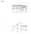
- An inkjet dyeing apparatus 1 as shown in Fig. 1 is an inkjet dyeing apparatus that dyes a belt-like textile T by ejecting ink, which includes a feeding section 2 for transporting the textile T to a front surface printing line Lf, a front surface printing section 3, disposed on the front surface printing line Lf, which dyes the front surface of the textile T by ejecting ink, a front surface drying section 4 for drying the front surface of the textile T, an inverting section 5 that inverts the textile T and carries the textile T to the rear surface printing line Lr, a rear surface printing section 6, disposed on the rear surface printing line Lr, which dyes the rear surface of the textile T by ejecting ink, a rear surface drying section 7 for drying the rear surface of the textile T, a transporting section 8 for transporting the textile T to the next step, and a control unit 9 for controlling the ejecting of the ink.
- the textile T is a belt-like textile such as seat belt webbing or the like.
- the textile T is supported by a plurality of transporting rollers R1 to R16 while being transported in the inkjet dyeing apparatus 1.
- Some of the transporting rollers R1 to R16 consist of transporting rollers each of which is rotated around its axis by an electric motor, and may be structured so as to exert transporting force to the textile T.
- the arrangement of the transporting rollers R1 to R16 shown in Fig. 1 is shown as an example and is not limited to this.
- the feeding section 2 and the transporting section 8 consist of, for example, dancer rolls 21, 81 and tension rolls 22, 82 and are structured so as to enable the elongation of the textile T to be freely adjusted between the feeding section 2 and the transporting section 8.
- the elongation provided to the textile T by the feeding section 2 and the transporting section 8 is appropriately determined according to conditions such as the material, thickness, and width of the textile T and the type of ink and the like.
- the feeding section 2 and the transporting section 8 may be individually adjusted on an automatic basis in such a manner that each of them can give a certain amount of elongation to the textile T.
- the elongation may be adjusted on an automatic basis by measuring each tension and performing feeding back of the tension through the control unit 9.
- a tension measuring instrument may be provided on any of the transporting rollers R3 to R5, R10 to R12 disposed in the vicinity of the front surface printing section 3 and the rear surface printing section 6, thereby monitoring the textile T for elongation at printing sections 3, 6 in order to allow the feeding section 2 and the transporting section 8 to adjust the elongation provided to the textile T.
- the front surface printing section 3 and the rear surface printing section 6 have inkjet heads 31, 61 and ink tanks 32, 62.
- the inkjet head 31 has a width Wi larger than the width Wt of the textile T and is secured onto the front surface printing line Lf.
- Use of the inkjet head 31 having a width Wi larger than the width Wt of the textile T allows ink to be ejected to the textile T without moving the inkjet head 31 in a horizontal plane, allows a plurality of textiles T to be simultaneously printed, and also allows ink to be easily sprayed to the sides of the textile T.
- a small head capable of high-speed driving, for example, complying with thin-film piezo inkjet head specifications is used as the inkjet head 31.
- the number of textiles T that can be printed simultaneously is determined by the relationship between the width Wt of the textile T and the width Wi of the inkjet head 31.
- Four front surface printing lines Lf can be disposed as shown in Fig. 2(A) , or two front surface printing lines Lf can be disposed as shown in Fig. 2(B) .
- four front surface printing lines Lf can be disposed as shown in Fig. 2(A) .
- two front surface printing lines Lf can be disposed as shown in Fig. 2(B) . Even in the case where a plurality of textiles T can be printed simultaneously, one front surface printing line Lf may be used to print the textile T.
- each of the front surface printing section 3 and the rear surface printing section 6 is divided into two, in which the upstream printing sections 3, 6 jet, for example, yellow and magenta inks, while the downstream printing sections 3 jet, for example, cyan and black inks.
- the upstream ink tanks 32, 62 of the printing sections 3, 6 are charged with yellow and magenta inks, respectively, while the downstream ink tanks 32, 62 are charged with cyan and black inks, respectively.
- each of the printing sections 3, 6 may consist of one inkjet head 31, 61 and ink tank 32, 62 so as to be able to simultaneously jet yellow, magenta, cyan, and black inks.
- each of the printing sections 3, 6 may consist of four inkjet heads 31, 61 and ink tanks 32, 62 so as to be able to jet yellow, magenta, cyan, and black inks individually.
- the ink may be either dye-based or pigmented.
- the front surface printing section 3 and the rear surface printing section 6 are similar to other ordinary inkjet printing mechanisms except that fixed inkjet heads 31, 61 are used, and detailed descriptions thereof are omitted.
- the front surface drying section 4 and the rear surface drying section 7 consist of, for example, an electric heater. In these sections, an amount of heat is sufficient such that the textile T is dried to such a degree that the ink does not migrate to the transporting rollers R6 to R16. As shown in Fig. 1 , the textile T is transported in the shape of a U through the transporting rollers R5, R12 to R8, R15, and the front surface drying section 4 and the rear surface drying section 7 are disposed in recesses created below the transporting path of the textile T. In other words, the textile T is transported in such a manner that its surface immediately after being subjected to inkjet printing faces each of the drying sections 4, 7.
- the distance between the textile T and each of the drying sections 4, 7 is determined by the amount of heat generated by the electric heater or the type and the amount of ink ejected to the textile T.
- the transporting rollers R6, R7, R13, R14 may be omitted so that the textile T is transported straight, and the front surface drying section 4 and the rear surface drying section 7 may be disposed between the transporting rollers R5, R12 and the transporting rollers R8, R15, respectively.
- the inverting section 5 is a section that inverts the textile T whose front surface has been printed so as to allow its rear surface to be printed.
- the textile T needs to be turned by 180 degrees.
- turning the textile T by 180 degrees at a time causes the front and rear surfaces to come into contact with each other, which results in ink wear or ink migration.
- textile inversion is accomplished by turning the textile by approximately 90 degrees followed by further turning the textile by approximately 90 degrees, namely, turning in two steps, 90 degrees at a time. As shown in Fig.
- inverting sections 5 may be provided in the transporting path so that they can invert the textiles T, respectively.
- one inverting section 5 may be adapted to invert four textiles T all together.
- Fig. 3 is a diagram showing an inverting section.
- Fig. 3(A) is an expanded view.
- Fig. 3(B) is a view as seen from arrow B of Fig. 3(A) .
- shadow areas of the textile T represent printed surfaces (front surface). As shown in Figs.
- the inverting section 5 includes a first guide section 51 that carries the textile T on the front surface printing line Lf to an inverting line Lm substantially perpendicular to the front surface printing line Lf, a second guide section 52 that carries the textile to the rear surface printing line Lr substantially perpendicular to the inverting line Lm, and an intermediate guide line 53 that causes the textile T on the inverting line Lm to make a U-turn.
- the first guide section 51, the second guide section 52, and the intermediate guide section 53 may consist of a cylindrical guide bar slidable with the textile T or a transporting roller. Illustrations of the supporting members that support the first guide section 51, the second guide section 52, and the intermediate guide section 53 are omitted.
- the shaft center J1 of the first guide section 51 is disposed at approximately 90 degrees relative to the shaft center (perpendicular to the top face of page) of the last transporting roller R9 on the front surface printing line Lf, transporting the textile T to the inverting line Lm substantially perpendicular to the front surface printing line Lf.
- the intermediate guide section 53 is disposed on the inverting line Lm to cause the textile T to make a U-turn.
- the intermediate guide section 53 is disposed in such a manner that its shaft center J3 is set at approximately 90 degrees relative to the shaft centers J1, J2 of the first guide section 51 and the second guide section 52.
- the intermediate guide section 53 may consist of one guide bar although it consists of two guide bars in this embodiment.
- the second guide section 52 is disposed in such a manner that it has the shaft center J2 coaxial with the shaft center J1 of the first guide section 51.
- the transporting distance D1 between the first guide section 51 and the intermediate guide section 53 is set to be equal to the transporting distance D2 between the intermediate guide section 53 and the second guide section 52.
- the shaft center J2 of the second guide section 52 is disposed at approximately 90 degrees relative to the shaft center J10 of the first transporting roller R10 on the rear surface printing line Lr, transporting the textile T to the rear surface printing line Lr substantially perpendicular to the inverting line Lm.
- the side edges Er, El of the textile T are indicated by dashed lines and dashed-dotted lines, respectively, in Figs. 3(A) and 3(B) , and routing of the textile T in the inverting section 5 is described below.
- the edge Er on the right-hand side in the direction of movement of the textile T in the transporting roller R9 is indicated by dashed lines
- the edge El on the left-hand side in the direction of movement of the textile T is indicated by dashed-dotted lines.
- a determination as to whether Er or El is on the right-hand side or on the left-hand side is made by viewing from overhead the textile T passing through the transporting roller R9.
- the textile T is transported through the first guide section 51 in such a manner that the surface (front surface) to be subjected to printing is disposed at the side (outer side) which does not come into contact with the first guide section 51.
- edge Er (dashed lines) runs around the upper side of the intermediate guide section 53, while the edge El (dashed-dotted lines) runs around the lower side of the intermediate guide section 53.
- the textile T is routed in such a manner that the edge Er (dashed lines) running around the upper side of the intermediate guide section 53 is disposed on the left side of the second guide section 52, while the edge El (dashed-dotted lines) running around the lower side of the intermediate guide section 53 is disposed on the right side of the second guide section 52. Accordingly, as shown in Fig. 3(B) , the textile T is transported through the second guide section 52 in such a manner that the surface (front surface) to be subjected to printing is disposed at the side (inner side) which comes into contact with the second guide section 52.
- the control unit 9 is a section that mainly controls the amount of ink to be ejected and ink ejecting timing for the front surface printing section 3 and the rear surface printing section 6.
- the control unit 9 stores or has data for colors and patterns to be printed on the textile T transmitted thereto, and, on the basis of such data, jets yellow, magenta, cyan, and black inks to the textile T.
- the control unit 9 may be either a dedicated controller provided in the inkjet dyeing apparatus 1 or a computer connected online or via a network to the inkjet dyeing apparatus 1.
- control unit 9 may be adapted to monitor the elongation of the textile T while it controls ink ejecting timing as well as the elongation of the textile T of the feeding section 2 and the transporting section 8. As just described above, the control unit 9 adjusts ejecting timing to meet the elongation of the textile running on the front surface printing line Lf and the rear surface printing line Lr, thereby preventing ink misalignment to print aesthetically beautiful designs and patterns even when yellow, magenta, cyan, and black inks, for example, are superposed.
- the textile T can be transported to the inkjet dyeing apparatus 1 from the feeding section 2, transported to the front surface printing section 3 through the transporting rollers R1 to R4, transported to the front surface drying section 4 through the transporting rollers R5 to R8, inverted by the inverting section 5 between the transporting rollers R9 and R10, transported to the rear surface printing section 6 through the transporting roller R10 and R11, transported to the rear surface drying section 7 through the transporting rollers R12 to R15, transported out to the transporting section 8 through the transporting roller R16, and the textile T subjected to printing on both surfaces thereof can be transported to the next step.
- the inkjet dyeing apparatus 1 can implement the inkjet dyeing method which includes the feeding step of feeding the textile T to the inkjet dyeing apparatus 1, the front surface printing step of dyeing by ejecting ink onto the front surface of the textile T, the front surface drying step of drying the front surface of the textile T, the inverting step of inverting the textile T, the rear surface printing step of dyeing by ejecting ink onto the rear surface of the textile T, and the rear surface drying step of drying the rear surface of the textile T.
- FIG. 4 is a configuration diagram showing an inkjet dyeing apparatus according to a second embodiment of the present invention.
- Fig. 5 is a configuration diagram showing an inkjet dyeing apparatus according to a third embodiment of the present invention.
- the reference numerals and symbols in these figures refer to the same components as those with the same reference numerals and symbols in Fig. 1 showing an inkjet dyeing apparatus according to a second embodiment, and repeated descriptions of the same components are omitted.
- the inkjet dyeing apparatus 1 includes a feeding section 2 for feeding a textile T to a front surface printing line Lf, a front surface printing section 3, disposed on the front surface printing line Lf, which dyes the textile by ejecting ink onto the front surface of the textile T, a front surface drying section 4 for drying the front surface of the textile T, an inverting section 5 that inverts and feeds the textile T to the rear surface printing line Lr, a rear surface printing section 6, disposed on the rear surface printing line Lr, which dyes the textile by ejecting ink onto the rear surface of the textile T, a rear surface drying section 7 for drying the rear surface of the textile T, a transporting section 8 for transporting out the textile T to the next step, and a control unit 9 for controlling the ejecting of the ink.
- the textile T is transported through a plurality of transporting rollers R1 to R29 in the in
- the inkjet dyeing apparatus 1 has the front surface drying section 4 and the inverting section 5 disposed below the front surface printing section 3 and has the rear surface drying section 7 disposed below the rear surface printing section 6.
- disposing the drying sections 4, 7 and the inverting section 5 below the printing sections 3, 6 can reduce dead spaces inside the inkjet dyeing apparatus, thereby allowing downsizing of the apparatus.
- the overall length L of the inkjet dyeing apparatus 1 can be reduced.
- the textile T can be transported to the inkjet dyeing apparatus 1 from the feeding section 2, transported to the front surface printing section 3 through the transporting rollers R1 to R4, transported back to below the upstream front surface printing section 3 through transporting rollers R5 to R7, transported to the front surface drying section 4 through the transporting rollers R8 to R13, inverted by the inverting section 5 between the transporting rollers R14 and R15, transported to the rear surface printing section 6 through the transporting roller R16 and R18, transported back to below the upstream rear surface printing section 6 through the transporting rollers R19 to R21, transported to the rear surface drying section 7 through the transporting rollers R22 to R28, transported to the transporting section 8 through the transporting roller R29, and the textile T subjected to printing on both surfaces thereof can be transported to the next step.
- the inkjet dyeing apparatus 1 includes a feeding section 2 for feeding a textile T to a front surface printing line Lf, a printing section 10, disposed on the front surface printing line Lf, which dyes the textile by ejecting onto the front surface of the textile T, a front surface drying section 4 for drying the front surface of the textile T, an inverting section 5 that inverts and feeds the textile T to the rear surface printing line Lr, a printing section 10, disposed on the rear surface printing line Lr, which dyes the textile by ejecting ink onto the rear surface of the textile T, a rear surface drying section 7 for drying the rear surface of the textile T, a transporting section 8 for transporting out the textile T to the next step, and a control unit 9 for controlling the ejecting of the ink.
- the printing section 10 has a structure similar to that of the front surface printing section 3 or the rear surface printing section 6, including an inkjet head 101 and a ink tank 102.
- the textile T is transported through a plurality of transporting rollers R1 to R19 in the inkjet dyeing apparatus 1.
- the front surface printing line Lf and the rear surface printing line Lr are disposed in the form of a loop in such a manner that they are in parallel to each other and are directed toward the same direction of movement, while the front surface printing section and the rear surface printing section consist of the same printing section 10 (inkjet head 101).
- the textile T can be fed into the inkjet dyeing apparatus 1 from the feeding section 2, transported to the printing section 10 through the transporting rollers R1 to R4 to cause the front surface of the textile T to be printed, transported back to below the upstream printing section 10 through the transporting rollers R5 to R12, inverted by the inverting section 5 between the transporting rollers R9 and R10 or between the transporting rollers R10 and R11, dried by the front surface drying section 4 disposed between the inverting section 5 and the transporting rollers R9, R10 or the transporting rollers R10, R11, again transported to the printing section 10 through the transporting rollers R2 to 4 to cause the rear surface of the textile T to be printed, transported back to below the upstream printing section 10 through the transporting rollers R5 to R7, transported to the rear surface drying section 7 through the transporting rollers R13 to R18, transported to the transporting section 8 through the transporting roller R19, and the textile T subjected to both
- the textile T is transported in the form of a loop so as to allow the front surface printing step and the rear surface printing step to be simultaneously performed.
- transporting the textile T to the printing section 10 in the form of a loop in the apparatus allows the printing section 10 to print both surfaces of the textile T, thereby allowing downsizing of the apparatus.
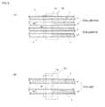
- Fig. 6 is a view as seen from the line A-A of Fig. 5 .
- Fig. 6(A) shows the case where two textiles are subjected to printing.
- Fig. 6(B) shows the case where one textile is subjected to printing. Shadow areas in each figure show the printed state of a textile, while shaded areas show the state where a printed surface is disposed at the rear side.
- the inkjet dyeing apparatus 1 according to a first embodiment can print four textiles T simultaneously since it has the front surface printing section 3 and the rear surface printing section 6 separately provided.
- the inkjet dyeing apparatus 1 has the printing section 10 provided for the purpose of both front surface and rear surface printing, which uses two lines for the front surface printing line Lf and the rear surface printing line Lr of the first textile T, and other two lines for the front surface printing line Lf and the rear surface printing line Lr of the first textile T, as shown in Fig. 6(A) .
- the front surface printing line Lf and the rear surface printing line Lr of the first and second textiles T are disposed in the printing section 10 in such a manner that they are in parallel to each other and are directed toward the same direction of movement. This is because, as shown in Fig. 5 , transporting the textile T in the form of a loop through the transporting rollers R2 to R12 allows the front surface printing line Lf and the rear surface printing line Lr to be disposed in the printing section 10 through one path.
- the inkjet head 101 has a width Wi of, for example, 230mm and the textile T has a width Wt of 50mm (equivalent to the width of an ordinary webbing)
- two sets of the front surface printing line Lf and the rear surface printing line Lr consisting of one path can be disposed, as shown in Fig. 6(A) .
- the inkjet head 101 has a width Wi of 230mm and the textile T has a width Wt of 80mm (equivalent to the width of race car webbing or air belts)
- one set of the front surface printing line Lf and the rear surface printing line Lr consisting of one path can be disposed, as shown in Fig. 6(B) .
- one set of the front surface printing line Lf and the rear surface printing line Lr may be used to print the textile T.
- Fig. 7 is a diagram showing an inverting section according to a third embodiment.
- Fig. 7(A) is an expanded view.
- Fig. 7(B) is a view as seen from B of Fig. 7(A) .
- shadow areas of the textile T represent printed surfaces (front surface). As shown in Figs.
- the inverting section 5 may consist of a first guide section 51 that carries the textile T on the front surface printing line Lf to an inverting line Lm substantially perpendicular to the front surface printing line Lf, a second guide section 52 that carries the textile to the rear surface printing line Lr substantially perpendicular to the inverting line Lm, and an intermediate guide line 53 that allows the textile T on the inverting line Lm to make a U-turn.
- Fig. 5 depicts two inverting sections 5a, 5b, which represent the structure where an inverting section 5a for the first textile T and an inverting section 5b for the second textile T are separately provided.
- the inverting and routing methods, as shown in Fig. 7 , for the textile T in the inverting section 5 according to the third embodiment are the same as those for the inverting section 5 according to the first embodiment.
- the transporting distance D1 between the first guide section 51 and the intermediate guide section 53 and the transporting distance D2 between the intermediate guide section 53 and the second guide section 52 are set to be different from each other.
- Different transporting distances D1, D2 as just described allow the transporting lines for the pre-inverted and post-inverted textiles T to be shifted from each other, thereby enabling the textile T to be inverted in such a manner that the pre-inverted and post-inverted textiles T run in parallel to each other and thereby enabling the front surface printing line Lf and the rear surface printing line Lr to be disposed in such a manner that they are in parallel to each other and directed toward the same direction of movement.
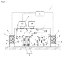
- Fig. 8 is a configuration diagram showing an inkjet dyeing apparatus according to a fourth embodiment of the present invention.
- the fourth embodiment as shown in Fig. 8 has a second drying step for drying both surfaces of the textile T, which follows the rear surface drying step.
- the inkjet dyeing apparatus 11 according to the fourth embodiment is the inkjet dyeing apparatus 1 according to the first to third embodiments, which has a second drying section 113 provided downstream thereof for securely drying both surfaces of the textile T subjected to both-surface printing, thereby developing ink as well as fixing ink to the textile T.
- the second drying section 113 includes, for example, an electrically-heated oven having an electrical heater 113a therein, which has a plurality of transporting rollers R provided therein for causing the textile T to meander.
- the inkjet dyeing equipment as shown in Fig. 8 includes a feeding dolly 111 for transporting a pre-dyed, plain textile T, a first relaying section 112 for relaying downstream the textile T on the feeding dolly 111, an inkjet dyeing apparatus 11 for printing the textile T, a cooling section 114 for cooling the textile T subjected to the second drying step, a transporting section 115 for transporting out the textile T subjected to the second drying step, a second relaying section 116 for relaying downstream the textile T subjected to the second drying step, and a transporting dolly 117 for transporting the textile T subjected to dyeing.
- the textile T subjected to dyeing by the inkjet dyeing equipment may be washed to add texture after recovered with the transporting dolly 117, or the printed surfaces may be coated with a resin for protecting the printed surface.
- the inkjet dyeing equipment may be structured so as to allow the washing step and the resin coating step to be successively performed following the second drying step.
- the relaying section 112 includes a drum 112a for receiving the textile T from the feeding dolly 111, a transporting roller R for transporting the textile T, and a support pillar 112b for supporting the drum 112a and the transporting roller R.
- the cooling section 114 is a section for allowing the textile T subjected to the second drying step to dry naturally, transporting the textile T by a certain distance through a plurality of transporting rollers R.
- the transporting section 115 has a dancer roll 115a and a tension roll 115b. A predetermined elongation is given to the textile T between the transporting sections 8, 115.
- the second relaying section 116 includes a drum 116a for passing the textile T to the transporting dolly 117, a transporting roller R for transporting the textile T, and a support pillar for supporting the drum 116a and the transporting roller R.
- the drum 116a may be movably disposed on the support pillar 116b.
Landscapes
- Health & Medical Sciences (AREA)
- General Health & Medical Sciences (AREA)
- Toxicology (AREA)
- Engineering & Computer Science (AREA)
- Textile Engineering (AREA)
- Coloring (AREA)
- Treatment Of Fiber Materials (AREA)
- Ink Jet (AREA)
- Application Of Or Painting With Fluid Materials (AREA)
Abstract
Description
- The present invention relates to an inkjet dyeing method and apparatus, and more specifically, it relates to an inkjet dyeing method and apparatus suitable for continuous printing on a belt-like textile such as seat belt webbing.
- As a dyeing method for seat belt webbing, a method disclosed in, for example,
JP Patent 3240674 Patent Document 1, seat belt webbing is subjected to a certain amount of tension with a first tensioner and a second tensioner while it is immersed in a dye solution in a dye padding process for dye attachment and dried in a hot-air oven for dye developing and fixing. - Also, a method disclosed in, for example,
JP-A-5-318721 - The dyeing method disclosed in
Patent Document 1, however, causes problems that one-color dyeing with no patterns can only be achieved since webbing is immersed in a dye solution, that a large space is required for a water bath for a dye solution and a hot-water washing solution, and that necessity for treatment of waste dyeing solution as well as installations such as a gas tank and a steam boiler and the like leads in an increase in burdens on the environment. - The recording method described in Patent Document 2 also has a disadvantage in that it is mainly for use in single-side printing since it is intended mainly for a cloth and textile used for clothing and wallpaper and does not mention its application to two-side printing. Furthermore, the recording method described in Patent Document 2 is not suitable for high-speed printing since due to its extended range of printing an ink head is moving on a printed surface while ejecting an ink.
- Accordingly, the present invention has been achieved in light of the foregoing and an object thereof is to provide an inkjet dyeing method and apparatus suitable for continuous printing for a belt-like textile such as seat belt webbing, which allows various colors and patterns to be printed on both sides of a textile while reducing burdens on the environment.
- The present invention provides an inkjet dyeing method for dyeing a belt-like textile by ejecting ink, which includes a feeding step of feeding the textile to an inkjet dyeing apparatus, a front surface printing step of dyeing the textile by ejecting ink onto the front surface of the textile, a front surface drying step of drying the front surface of the textile, an inverting step of inverting the textile, a rear surface printing step of dyeing the textile by ejecting ink onto the rear surface of the textile, and a rear surface drying step of drying the rear surface of the textile. The textile may be conveyed in the form of a loop so that the front surface printing step and the rear surface printing step can be simultaneously performed.
- In the inverting step described above, textile inverting may be accomplished by turning the textile by approximately 90 degrees followed by further turning the textile by approximately 90 degrees. Also, in the inverting step, the textile may be inverted in such a manner that the pre-inverted textile and the post-inverted textile run in parallel.
- In the front surface drying step and the rear surface drying step, the textile may be dried to such a degree that the ink does not migrate to a transporting roller. Also, a second drying step of drying both sides of the textile may be provided following the rear surface drying step.
- Furthermore, the present invention provides an inkjet dyeing apparatus for dyeing a belt-like textile by ejecting ink, which includes a feeding section for feeding a textile to a front surface printing line, a front surface printing section, disposed on the front surface printing line, which dyes the textile by ejecting ink onto the front surface of the textile, a front surface drying section for drying the front surface of the textile, an inverting section that inverts and feeds the textile to the rear surface printing line, a rear surface printing section, disposed on the rear surface printing line, which dyes the textile by ejecting ink onto the rear surface of the textile, a rear surface drying section for drying the rear surface of the textile, a transporting section for transporting the textile to the next step, and a control unit for controlling the ejecting of the ink. A second drying section for drying both sides of the textile may be provided downstream of the transporting section.
- Preferably, the front surface printing section and the rear surface printing section consist of inkjet heads secured to the front surface printing line and the rear surface printing line. The front surface printing line and the rear surface printing line are disposed in the form of a loop in such a manner that they are in parallel to each other and are directed toward the same direction of movement, while the front surface printing section and the rear surface printing section may consist of the same inkjet head. The front surface drying section, the inverting section, and the rear surface drying section may be disposed below the front surface printing line and the rear surface printing line.
- The inverting section may consist of a first guide section for transporting the textile on the front surface printing line to an inverting line substantially perpendicular to the front surface printing line, a second guide section for transporting the textile to the rear surface printing line substantially perpendicular to the inverting line, and an intermediate guide line for allowing the textile on the inverting line to make a U-turn. The transporting distance between the first guide section and the intermediate guide section and the transporting distance between the intermediate guide section and the second guide section may be set to be different from each other.
- It is preferable that the feeding section and the transporting section are structured so as to give the textile a certain amount of elongation. Also, the control unit may be structured so that ejecting timing of the ink is adjusted to suit the elongation of the textile on the front surface printing line and the rear surface printing line.
- The inkjet dyeing method and apparatus according to the present invention described above allow a textile with its front surface subjected to printing to be inverted so as to enable its rear surface to be ready for printing, thereby allowing both surfaces of the textile to be easily subjected to continuous printing. Use of inkjet systems as a method for dyeing a belt-like textile such as seat belt webbing enables a textile to be dyed without using a dyeing solution that requires waste solution treatment processes, which leads to a reduction in burdens on the environment. Also, it eliminates necessity for installations such as a gas tank or a steam boiler and the like, leading to downsizing of installations, cost reduction, and a reduction in burdens on the environment. Furthermore, it allows dyeing without immersing the textile in a dye solution, enabling various colors and patterns to be printed which gives an added-value of designs to seat belt webbing that otherwise appears monotonous. In addition, product information contained in a tag, which has conventionally been attached to seat belt webbing after dyeing process, can be printed on the surface of the seat belt webbing, resulting in a reduction in manufacturing man-hours.
- The textile is transported in such a manner that both-side printing can be provided simultaneously, thereby effectively reducing the size of the apparatus. Also, for textile inversion, the textile is smoothly inverted by inverting the textile by 90 degrees at a time, thereby preventing the front and rear surfaces of the textile from coming into contact with each other during inversion which causes ink wear or color migration. Furthermore, the pre-inverted textile and the post-inverted textile run in parallel, thereby allowing the textile to be transported in such a manner that the front surface printing line and the rear surface printing line are in parallel with each other and are directed toward the same direction as well as allowing both sides of the textile to be simultaneously printed at one path, resulting in improved printing efficiency.
- Also, an appropriate drying step inserted after the front surface printing and rear surface printing allows excessive ink content to be dried, thereby suppressing color migration to the transporting roller. Furthermore, the second drying step (second drying section) for securely drying both sides of the textile allows ink to produce color as well as allows ink to be fixed to the textile.
- Also, a certain amount of elongation provided to the textile allows printing accuracy to be improved, thereby allowing the textile to give beautiful patterns under normal conditions (service conditions). Furthermore, even if yellow, magenta, cyan, and black colors are over-painted, ink misalignment can be prevented, thereby allowing beautiful designs or patterns to be printed.
- Also, disposing the drying section and the inverting section below the printing sections (front surface printing section and rear surface printing section) can reduce dead spaces inside the inkjet dyeing apparatus, thereby allowing downsizing of the apparatus.
- An embodiment of the present invention will be described below with reference to
Figs. 1 to 8 . -
Fig. 1 is a configuration diagram showing an inkjet dyeing apparatus according to a first embodiment of the present invention; -
Fig. 2 is a view as seen from the line A-A ofFig. 1 .Fig. 2(A) shows the case where four textiles are subjected to printing;Fig. 2 (B) shows the case where two textiles are subjected to printing; -
Fig. 3 is a diagram showing an inverting section.Fig. 3(A) is an expanded view;Fig. 3(B) is a view as seen from B ofFig. 3(A) ; -
Fig. 4 is a configuration diagram showing an inkjet dyeing apparatus according to a second embodiment of the present invention; -
Fig. 5 is a configuration diagram showing an inkjet dyeing apparatus according to a third embodiment of the present invention; -
Fig. 6 is a view as seen from the line A-A ofFig. 5 .Fig. 6(A) shows the case where two textiles are subjected to printing;Fig. 6(B) shows the case where one textile is subjected to printing; -
Fig. 7 is a diagram showing an inverting section according to a third embodiment;Fig. 7(A) is an expanded view.Fig. 7(B) is a view as seen from B ofFig. 7(A) ; and -
Fig. 8 is a configuration diagram showing an inkjet dyeing apparatus according to a fourth embodiment of the present invention. - An
inkjet dyeing apparatus 1 as shown inFig. 1 is an inkjet dyeing apparatus that dyes a belt-like textile T by ejecting ink, which includes a feeding section 2 for transporting the textile T to a front surface printing line Lf, a frontsurface printing section 3, disposed on the front surface printing line Lf, which dyes the front surface of the textile T by ejecting ink, a frontsurface drying section 4 for drying the front surface of the textile T, an invertingsection 5 that inverts the textile T and carries the textile T to the rear surface printing line Lr, a rear surface printing section 6, disposed on the rear surface printing line Lr, which dyes the rear surface of the textile T by ejecting ink, a rearsurface drying section 7 for drying the rear surface of the textile T, atransporting section 8 for transporting the textile T to the next step, and acontrol unit 9 for controlling the ejecting of the ink. - The textile T is a belt-like textile such as seat belt webbing or the like. The textile T is supported by a plurality of transporting rollers R1 to R16 while being transported in the
inkjet dyeing apparatus 1. Some of the transporting rollers R1 to R16 consist of transporting rollers each of which is rotated around its axis by an electric motor, and may be structured so as to exert transporting force to the textile T. The arrangement of the transporting rollers R1 to R16 shown inFig. 1 is shown as an example and is not limited to this. - The feeding section 2 and the
transporting section 8 consist of, for example, dancer rolls 21, 81 andtension rolls transporting section 8. The elongation provided to the textile T by the feeding section 2 and thetransporting section 8 is appropriately determined according to conditions such as the material, thickness, and width of the textile T and the type of ink and the like. For adjustment of elongation provided to the textile T, the feeding section 2 and thetransporting section 8 may be individually adjusted on an automatic basis in such a manner that each of them can give a certain amount of elongation to the textile T. Alternatively, the elongation may be adjusted on an automatic basis by measuring each tension and performing feeding back of the tension through thecontrol unit 9. Also, a tension measuring instrument may be provided on any of the transporting rollers R3 to R5, R10 to R12 disposed in the vicinity of the frontsurface printing section 3 and the rear surface printing section 6, thereby monitoring the textile T for elongation atprinting sections 3, 6 in order to allow the feeding section 2 and thetransporting section 8 to adjust the elongation provided to the textile T. - The front
surface printing section 3 and the rear surface printing section 6 have inkjetheads ink tanks Fig. 2 , theinkjet head 31 has a width Wi larger than the width Wt of the textile T and is secured onto the front surface printing line Lf. Use of theinkjet head 31 having a width Wi larger than the width Wt of the textile Tallows ink to be ejected to the textile T without moving theinkjet head 31 in a horizontal plane, allows a plurality of textiles T to be simultaneously printed, and also allows ink to be easily sprayed to the sides of the textile T. A small head capable of high-speed driving, for example, complying with thin-film piezo inkjet head specifications is used as theinkjet head 31. The number of textiles T that can be printed simultaneously is determined by the relationship between the width Wt of the textile T and the width Wi of theinkjet head 31. Four front surface printing lines Lf can be disposed as shown inFig. 2(A) , or two front surface printing lines Lf can be disposed as shown inFig. 2(B) . For example, in the case where the inkjet head has a width Wi of 230mm and the textile T has a width Wt of 50mm (equivalent to the width of ordinary webbing), four front surface printing lines Lf can be disposed as shown inFig. 2(A) . Also, in the case where the inkjet head has a width Wi of 230mm and the textile T has a width Wt of 80mm (equivalent to the width of race car webbing or air belts), two front surface printing lines Lf can be disposed as shown inFig. 2(B) . Even in the case where a plurality of textiles T can be printed simultaneously, one front surface printing line Lf may be used to print the textile T. - Also, as shown in
Fig. 1 , each of the frontsurface printing section 3 and the rear surface printing section 6 is divided into two, in which theupstream printing sections 3, 6 jet, for example, yellow and magenta inks, while thedownstream printing sections 3 jet, for example, cyan and black inks. In other words, theupstream ink tanks printing sections 3, 6 are charged with yellow and magenta inks, respectively, while thedownstream ink tanks printing sections 3, 6 may consist of oneinkjet head ink tank printing sections 3, 6 may consist of four inkjet heads 31, 61 andink tanks surface printing section 3 and the rear surface printing section 6 are similar to other ordinary inkjet printing mechanisms except that fixed inkjet heads 31, 61 are used, and detailed descriptions thereof are omitted. - The front
surface drying section 4 and the rearsurface drying section 7 consist of, for example, an electric heater. In these sections, an amount of heat is sufficient such that the textile T is dried to such a degree that the ink does not migrate to the transporting rollers R6 to R16. As shown inFig. 1 , the textile T is transported in the shape of a U through the transporting rollers R5, R12 to R8, R15, and the frontsurface drying section 4 and the rearsurface drying section 7 are disposed in recesses created below the transporting path of the textile T. In other words, the textile T is transported in such a manner that its surface immediately after being subjected to inkjet printing faces each of the dryingsections sections surface drying section 4 and the rearsurface drying section 7 may be disposed between the transporting rollers R5, R12 and the transporting rollers R8, R15, respectively. - The
inverting section 5 is a section that inverts the textile T whose front surface has been printed so as to allow its rear surface to be printed. To invert the textile T, the textile T needs to be turned by 180 degrees. However, turning the textile T by 180 degrees at a time causes the front and rear surfaces to come into contact with each other, which results in ink wear or ink migration. To solve the problem, according to the present invention textile inversion is accomplished by turning the textile by approximately 90 degrees followed by further turning the textile by approximately 90 degrees, namely, turning in two steps, 90 degrees at a time. As shown inFig. 2(A) , in the case where up to four textiles T can be printed at a time, four invertingsections 5 may be provided in the transporting path so that they can invert the textiles T, respectively. Alternatively, oneinverting section 5 may be adapted to invert four textiles T all together. -
Fig. 3 is a diagram showing an inverting section.Fig. 3(A) is an expanded view.Fig. 3(B) is a view as seen from arrow B ofFig. 3(A) . In these figures, shadow areas of the textile T represent printed surfaces (front surface). As shown inFigs. 3(A) and 3(B) , theinverting section 5 includes afirst guide section 51 that carries the textile T on the front surface printing line Lf to an inverting line Lm substantially perpendicular to the front surface printing line Lf, asecond guide section 52 that carries the textile to the rear surface printing line Lr substantially perpendicular to the inverting line Lm, and anintermediate guide line 53 that causes the textile T on the inverting line Lm to make a U-turn. Thefirst guide section 51, thesecond guide section 52, and theintermediate guide section 53 may consist of a cylindrical guide bar slidable with the textile T or a transporting roller. Illustrations of the supporting members that support thefirst guide section 51, thesecond guide section 52, and theintermediate guide section 53 are omitted. - As shown in
Figs. 3(A) and 3(B) , the shaft center J1 of thefirst guide section 51 is disposed at approximately 90 degrees relative to the shaft center (perpendicular to the top face of page) of the last transporting roller R9 on the front surface printing line Lf, transporting the textile T to the inverting line Lm substantially perpendicular to the front surface printing line Lf. Theintermediate guide section 53 is disposed on the inverting line Lm to cause the textile T to make a U-turn. Theintermediate guide section 53 is disposed in such a manner that its shaft center J3 is set at approximately 90 degrees relative to the shaft centers J1, J2 of thefirst guide section 51 and thesecond guide section 52. Theintermediate guide section 53 may consist of one guide bar although it consists of two guide bars in this embodiment. Thesecond guide section 52 is disposed in such a manner that it has the shaft center J2 coaxial with the shaft center J1 of thefirst guide section 51. In other words, as shown inFig. 3(B) , the transporting distance D1 between thefirst guide section 51 and theintermediate guide section 53 is set to be equal to the transporting distance D2 between theintermediate guide section 53 and thesecond guide section 52. The shaft center J2 of thesecond guide section 52 is disposed at approximately 90 degrees relative to the shaft center J10 of the first transporting roller R10 on the rear surface printing line Lr, transporting the textile T to the rear surface printing line Lr substantially perpendicular to the inverting line Lm. - The side edges Er, El of the textile T are indicated by dashed lines and dashed-dotted lines, respectively, in
Figs. 3(A) and 3(B) , and routing of the textile T in theinverting section 5 is described below. In these figures, the edge Er on the right-hand side in the direction of movement of the textile T in the transporting roller R9 is indicated by dashed lines, while the edge El on the left-hand side in the direction of movement of the textile T is indicated by dashed-dotted lines. A determination as to whether Er or El is on the right-hand side or on the left-hand side is made by viewing from overhead the textile T passing through the transporting roller R9. The textile T passing through the transportingroller 9 while keeping the relationship of (right side, left side) = (edge Er, edge El) is transported to thefirst guide section 51 while keeping such a relationship. In other words, the textile T is transported through thefirst guide section 51 in such a manner that the surface (front surface) to be subjected to printing is disposed at the side (outer side) which does not come into contact with thefirst guide section 51. In addition, the textile T passing through thefirst guide section 51 while keeping the relationship of (right side, left side) = (edge Er, edge El) is transported to theintermediate guide section 53 while keeping such a relationship. Accordingly, as shown inFig. 3(A) , the edge Er (dashed lines) runs around the upper side of theintermediate guide section 53, while the edge El (dashed-dotted lines) runs around the lower side of theintermediate guide section 53. The textile T passing through theintermediate guide section 53 while keeping the relationship of (right side, left side) = (edge Er, edge El) is inverted at thesecond guide section 52 so as to give the relationship of (right side, left side) = (edge El, edge Er). In other words, the textile T is routed in such a manner that the edge Er (dashed lines) running around the upper side of theintermediate guide section 53 is disposed on the left side of thesecond guide section 52, while the edge El (dashed-dotted lines) running around the lower side of theintermediate guide section 53 is disposed on the right side of thesecond guide section 52. Accordingly, as shown inFig. 3(B) , the textile T is transported through thesecond guide section 52 in such a manner that the surface (front surface) to be subjected to printing is disposed at the side (inner side) which comes into contact with thesecond guide section 52. The textile T passing through thesecond guide section 52 while keeping the relationship of (right side, left side) = (edge El, edge Er) is transported to the transporting roller R10 while keeping such relationship. Routing the textile T in theinverting section 5 as described above allows the textile T to be smoothly inverted. - The
control unit 9 is a section that mainly controls the amount of ink to be ejected and ink ejecting timing for the frontsurface printing section 3 and the rear surface printing section 6. Thecontrol unit 9 stores or has data for colors and patterns to be printed on the textile T transmitted thereto, and, on the basis of such data, jets yellow, magenta, cyan, and black inks to the textile T. Thecontrol unit 9 may be either a dedicated controller provided in theinkjet dyeing apparatus 1 or a computer connected online or via a network to theinkjet dyeing apparatus 1. Also, thecontrol unit 9 may be adapted to monitor the elongation of the textile T while it controls ink ejecting timing as well as the elongation of the textile T of the feeding section 2 and the transportingsection 8. As just described above, thecontrol unit 9 adjusts ejecting timing to meet the elongation of the textile running on the front surface printing line Lf and the rear surface printing line Lr, thereby preventing ink misalignment to print aesthetically beautiful designs and patterns even when yellow, magenta, cyan, and black inks, for example, are superposed. - According to the
inkjet dyeing apparatus 1 as described above, the textile T can be transported to theinkjet dyeing apparatus 1 from the feeding section 2, transported to the frontsurface printing section 3 through the transporting rollers R1 to R4, transported to the frontsurface drying section 4 through the transporting rollers R5 to R8, inverted by theinverting section 5 between the transporting rollers R9 and R10, transported to the rear surface printing section 6 through the transporting roller R10 and R11, transported to the rearsurface drying section 7 through the transporting rollers R12 to R15, transported out to the transportingsection 8 through the transporting roller R16, and the textile T subjected to printing on both surfaces thereof can be transported to the next step. Consequently, theinkjet dyeing apparatus 1 according to the present invention can implement the inkjet dyeing method which includes the feeding step of feeding the textile T to theinkjet dyeing apparatus 1, the front surface printing step of dyeing by ejecting ink onto the front surface of the textile T, the front surface drying step of drying the front surface of the textile T, the inverting step of inverting the textile T, the rear surface printing step of dyeing by ejecting ink onto the rear surface of the textile T, and the rear surface drying step of drying the rear surface of the textile T. - Another embodiment of an inkjet dyeing apparatus according to the present invention is described below.
Fig. 4 is a configuration diagram showing an inkjet dyeing apparatus according to a second embodiment of the present invention.Fig. 5 is a configuration diagram showing an inkjet dyeing apparatus according to a third embodiment of the present invention. The reference numerals and symbols in these figures refer to the same components as those with the same reference numerals and symbols inFig. 1 showing an inkjet dyeing apparatus according to a second embodiment, and repeated descriptions of the same components are omitted. - Like the first embodiment as shown in
Fig. 1 , theinkjet dyeing apparatus 1 according to a second embodiment, as shown inFig. 4 , includes a feeding section 2 for feeding a textile T to a front surface printing line Lf, a frontsurface printing section 3, disposed on the front surface printing line Lf, which dyes the textile by ejecting ink onto the front surface of the textile T, a frontsurface drying section 4 for drying the front surface of the textile T, aninverting section 5 that inverts and feeds the textile T to the rear surface printing line Lr, a rear surface printing section 6, disposed on the rear surface printing line Lr, which dyes the textile by ejecting ink onto the rear surface of the textile T, a rearsurface drying section 7 for drying the rear surface of the textile T, a transportingsection 8 for transporting out the textile T to the next step, and acontrol unit 9 for controlling the ejecting of the ink. The textile T is transported through a plurality of transporting rollers R1 to R29 in theinkjet dyeing apparatus 1. - The
inkjet dyeing apparatus 1 according to the second embodiment has the frontsurface drying section 4 and theinverting section 5 disposed below the frontsurface printing section 3 and has the rearsurface drying section 7 disposed below the rear surface printing section 6. As just described, disposing the dryingsections inverting section 5 below theprinting sections 3, 6 can reduce dead spaces inside the inkjet dyeing apparatus, thereby allowing downsizing of the apparatus. In particular, the overall length L of theinkjet dyeing apparatus 1 can be reduced. - According to the
inkjet dyeing apparatus 1 as described above, the textile T can be transported to theinkjet dyeing apparatus 1 from the feeding section 2, transported to the frontsurface printing section 3 through the transporting rollers R1 to R4, transported back to below the upstream frontsurface printing section 3 through transporting rollers R5 to R7, transported to the frontsurface drying section 4 through the transporting rollers R8 to R13, inverted by theinverting section 5 between the transporting rollers R14 and R15, transported to the rear surface printing section 6 through the transporting roller R16 and R18, transported back to below the upstream rear surface printing section 6 through the transporting rollers R19 to R21, transported to the rearsurface drying section 7 through the transporting rollers R22 to R28, transported to the transportingsection 8 through the transporting roller R29, and the textile T subjected to printing on both surfaces thereof can be transported to the next step. - The
inkjet dyeing apparatus 1 according to a third embodiment, as shown inFig. 5 , includes a feeding section 2 for feeding a textile T to a front surface printing line Lf, aprinting section 10, disposed on the front surface printing line Lf, which dyes the textile by ejecting onto the front surface of the textile T, a frontsurface drying section 4 for drying the front surface of the textile T, aninverting section 5 that inverts and feeds the textile T to the rear surface printing line Lr, aprinting section 10, disposed on the rear surface printing line Lr, which dyes the textile by ejecting ink onto the rear surface of the textile T, a rearsurface drying section 7 for drying the rear surface of the textile T, a transportingsection 8 for transporting out the textile T to the next step, and acontrol unit 9 for controlling the ejecting of the ink. Theprinting section 10 has a structure similar to that of the frontsurface printing section 3 or the rear surface printing section 6, including aninkjet head 101 and aink tank 102. The textile T is transported through a plurality of transporting rollers R1 to R19 in theinkjet dyeing apparatus 1. - In the
inkjet dyeing apparatus 1 according to the third embodiment, the front surface printing line Lf and the rear surface printing line Lr are disposed in the form of a loop in such a manner that they are in parallel to each other and are directed toward the same direction of movement, while the front surface printing section and the rear surface printing section consist of the same printing section 10 (inkjet head 101). According to theinkjet dyeing apparatus 1 as described above, the textile T can be fed into theinkjet dyeing apparatus 1 from the feeding section 2, transported to theprinting section 10 through the transporting rollers R1 to R4 to cause the front surface of the textile T to be printed, transported back to below theupstream printing section 10 through the transporting rollers R5 to R12, inverted by theinverting section 5 between the transporting rollers R9 and R10 or between the transporting rollers R10 and R11, dried by the frontsurface drying section 4 disposed between the invertingsection 5 and the transporting rollers R9, R10 or the transporting rollers R10, R11, again transported to theprinting section 10 through the transporting rollers R2 to 4 to cause the rear surface of the textile T to be printed, transported back to below theupstream printing section 10 through the transporting rollers R5 to R7, transported to the rearsurface drying section 7 through the transporting rollers R13 to R18, transported to the transportingsection 8 through the transporting roller R19, and the textile T subjected to both-surface printing can be transported to the next step. Accordingly, the textile T is transported in the form of a loop so as to allow the front surface printing step and the rear surface printing step to be simultaneously performed. As just described above, transporting the textile T to theprinting section 10 in the form of a loop in the apparatus allows theprinting section 10 to print both surfaces of the textile T, thereby allowing downsizing of the apparatus. -
Fig. 6 is a view as seen from the line A-A ofFig. 5 .Fig. 6(A) shows the case where two textiles are subjected to printing.Fig. 6(B) shows the case where one textile is subjected to printing. Shadow areas in each figure show the printed state of a textile, while shaded areas show the state where a printed surface is disposed at the rear side. As shown inFig. 2(A) , theinkjet dyeing apparatus 1 according to a first embodiment can print four textiles T simultaneously since it has the frontsurface printing section 3 and the rear surface printing section 6 separately provided. On the other hand, theinkjet dyeing apparatus 1 according to a third embodiment has theprinting section 10 provided for the purpose of both front surface and rear surface printing, which uses two lines for the front surface printing line Lf and the rear surface printing line Lr of the first textile T, and other two lines for the front surface printing line Lf and the rear surface printing line Lr of the first textile T, as shown inFig. 6(A) . In other words, the front surface printing line Lf and the rear surface printing line Lr of the first and second textiles T are disposed in theprinting section 10 in such a manner that they are in parallel to each other and are directed toward the same direction of movement. This is because, as shown inFig. 5 , transporting the textile T in the form of a loop through the transporting rollers R2 to R12 allows the front surface printing line Lf and the rear surface printing line Lr to be disposed in theprinting section 10 through one path. - Accordingly, in the case where the
inkjet head 101 has a width Wi of, for example, 230mm and the textile T has a width Wt of 50mm (equivalent to the width of an ordinary webbing), two sets of the front surface printing line Lf and the rear surface printing line Lr consisting of one path can be disposed, as shown inFig. 6(A) . Also, in the case where theinkjet head 101 has a width Wi of 230mm and the textile T has a width Wt of 80mm (equivalent to the width of race car webbing or air belts), one set of the front surface printing line Lf and the rear surface printing line Lr consisting of one path can be disposed, as shown inFig. 6(B) . Even in the case where a plurality of textiles T can be printed simultaneously as shown inFig. 6(A) , one set of the front surface printing line Lf and the rear surface printing line Lr may be used to print the textile T. -
Fig. 7 is a diagram showing an inverting section according to a third embodiment.Fig. 7(A) is an expanded view.Fig. 7(B) is a view as seen from B ofFig. 7(A) . In these figures, shadow areas of the textile T represent printed surfaces (front surface). As shown inFigs. 7(A) and3(B) , like theinverting section 5 according to a first embodiment, theinverting section 5 may consist of afirst guide section 51 that carries the textile T on the front surface printing line Lf to an inverting line Lm substantially perpendicular to the front surface printing line Lf, asecond guide section 52 that carries the textile to the rear surface printing line Lr substantially perpendicular to the inverting line Lm, and anintermediate guide line 53 that allows the textile T on the inverting line Lm to make a U-turn.Fig. 5 depicts two invertingsections inverting section 5a for the first textile T and aninverting section 5b for the second textile T are separately provided. - The inverting and routing methods, as shown in
Fig. 7 , for the textile T in theinverting section 5 according to the third embodiment are the same as those for theinverting section 5 according to the first embodiment. In theinverting section 5 according to the third embodiment as shown inFig. 7 , however, the transporting distance D1 between thefirst guide section 51 and theintermediate guide section 53 and the transporting distance D2 between theintermediate guide section 53 and thesecond guide section 52 are set to be different from each other. Different transporting distances D1, D2 as just described allow the transporting lines for the pre-inverted and post-inverted textiles T to be shifted from each other, thereby enabling the textile T to be inverted in such a manner that the pre-inverted and post-inverted textiles T run in parallel to each other and thereby enabling the front surface printing line Lf and the rear surface printing line Lr to be disposed in such a manner that they are in parallel to each other and directed toward the same direction of movement. - An inkjet dyeing apparatus according to a fourth embodiment of the present invention is described below.
Fig. 8 is a configuration diagram showing an inkjet dyeing apparatus according to a fourth embodiment of the present invention. The fourth embodiment as shown inFig. 8 has a second drying step for drying both surfaces of the textile T, which follows the rear surface drying step. In other words, the inkjet dyeing apparatus 11 according to the fourth embodiment is theinkjet dyeing apparatus 1 according to the first to third embodiments, which has asecond drying section 113 provided downstream thereof for securely drying both surfaces of the textile T subjected to both-surface printing, thereby developing ink as well as fixing ink to the textile T. Thesecond drying section 113 includes, for example, an electrically-heated oven having anelectrical heater 113a therein, which has a plurality of transporting rollers R provided therein for causing the textile T to meander. - The structure of the entire inkjet dyeing equipment having the inkjet dyeing apparatus 11 as described above is described below. The inkjet dyeing equipment as shown in
Fig. 8 includes a feeding dolly 111 for transporting a pre-dyed, plain textile T, a first relayingsection 112 for relaying downstream the textile T on the feeding dolly 111, an inkjet dyeing apparatus 11 for printing the textile T, acooling section 114 for cooling the textile T subjected to the second drying step, a transportingsection 115 for transporting out the textile T subjected to the second drying step, a second relayingsection 116 for relaying downstream the textile T subjected to the second drying step, and a transportingdolly 117 for transporting the textile T subjected to dyeing. Although not illustrated, the textile T subjected to dyeing by the inkjet dyeing equipment may be washed to add texture after recovered with the transportingdolly 117, or the printed surfaces may be coated with a resin for protecting the printed surface. Alternatively, the inkjet dyeing equipment may be structured so as to allow the washing step and the resin coating step to be successively performed following the second drying step. - The relaying
section 112 includes adrum 112a for receiving the textile T from the feeding dolly 111, a transporting roller R for transporting the textile T, and asupport pillar 112b for supporting thedrum 112a and the transporting roller R. Thecooling section 114 is a section for allowing the textile T subjected to the second drying step to dry naturally, transporting the textile T by a certain distance through a plurality of transporting rollers R. Like the transportingsection 8 of theinkjet dyeing apparatus 1 according to the first to third embodiments, the transportingsection 115 has adancer roll 115a and atension roll 115b. A predetermined elongation is given to the textile T between the transportingsections section 116 includes adrum 116a for passing the textile T to the transportingdolly 117, a transporting roller R for transporting the textile T, and a support pillar for supporting thedrum 116a and the transporting roller R. Thedrum 116a may be movably disposed on thesupport pillar 116b. - The present invention is typically described with reference to, but not limited to, the foregoing preferred embodiments. Various modifications are conceivable within the scope of the present invention, including a pretreatment to allow ink to adapt to the textile T or prevent ink from excessively soaking into the textile T before the textile T is fed into the
inkjet dyeing apparatus 1, 11.
Claims (15)
- An inkjet dyeing method for dyeing a belt-like textile by ejecting ink, comprising:a feeding step of feeding the textile to an inkjet dyeing apparatus;a front surface printing step of dyeing the textile by ejecting the ink onto the front surface of the textile;a front surface drying step of drying the front surface of the textile;an inverting step of inverting the textile;a rear surface printing step of dyeing the textile by ejecting the ink onto the rear surface of the textile; anda rear surface drying step of drying the rear surface of the textile.
- The inkjet dyeing method according to Claim 1, wherein the textile is transported in the form of a loop so that the front surface printing step and the rear surface printing step can be simultaneously performed.
- The inkjet dyeing method according to Claim 1 or 2, wherein, in the inverting step, textile inverting is accomplished by turning the textile by approximately 90 degrees followed by further turning the textile by approximately 90 degrees.
- The inkjet dyeing method according to Claim 1, 2, or 3, wherein in the inverting step the textile is inverted in such a manner that the pre-inverted textile and the post-inverted textile run in parallel.
- The inkjet dyeing method according to any one of Claims 1 to 4, wherein, in the front surface drying step and the rear surface drying step, the textile is dried to such a degree that the ink does not migrate to a transporting roller.
- The inkjet dyeing method according to any one of Claims 1 to 5, wherein a second drying step of drying both sides of the textile is provided following the rear surface drying step.
- An inkjet dyeing apparatus for dyeing a belt-like textile by ejecting ink, comprising:a feeding section for feeding a textile to a front surface printing line;a front surface printing section, disposed on the front surface printing line, which dyes the textile by ejecting the ink onto the front surface of the textile;a front surface drying section for drying the front surface of the textile;an inverting section that inverts and feeds the textile to the rear surface printing line;a rear surface printing section, disposed on the rear surface printing line, which dyes the textile by ejecting the ink onto the rear surface of the textile;a rear surface drying section for drying the rear surface of the textile;a transporting section for transporting the textile to a next step; anda control unit for controlling the ejecting of the ink.
- The inkjet dyeing apparatus according to Claim 7, wherein the front surface printing section and the rear surface printing section consist of inkjet heads secured to the front surface printing line and the rear surface printing line.
- The inkjet dyeing apparatus according to Claim 7 or 8, wherein the front surface printing line and the rear surface printing line are disposed in the form of a loop in such a manner that they are in parallel to each other and are directed toward the same direction of movement, and the front surface printing section and the rear surface printing section consist of the same inkjet head.
- The inkjet dyeing apparatus according to Claim 7, 8 or 9, wherein the inverting section consists of a first guide section for transporting the textile on the front surface printing line to an inverting line substantially perpendicular to the front surface printing line, a second guide section for transporting the textile to the rear surface printing line substantially perpendicular to the inverting line, and an intermediate guide line for causing the textile on the inverting line to make a U-turn.
- The inkjet dyeing apparatus according to Claim 10, wherein the transporting distance between the first guide section and the intermediate guide section and the transporting distance between the intermediate guide section and the second guide section are set to be different from each other.
- The inkjet dyeing apparatus according to any one of Claims 7 to 11, wherein the feeding section and the transporting section are structured so as to give the textile a certain amount of elongation.
- The inkjet dyeing apparatus according to Claim 12, wherein the control unit adjusts ejecting timing for the ink to suit the elongation of the textile on the front surface printing line and the rear surface printing line.
- The inkjet dyeing apparatus according to any one of Claims 7 to 13, wherein a second drying section for drying both sides of the textile is provided downstream of the transporting section.
- The inkjet dyeing apparatus according to any one of Claims 7 to 14, wherein the front surface drying section, the inverting section, and the rear surface drying section are disposed below the front surface printing line and the rear surface printing line.
Applications Claiming Priority (1)
| Application Number | Priority Date | Filing Date | Title |
|---|---|---|---|
| JP2008222775A JP5481047B2 (en) | 2008-08-29 | 2008-08-29 | Inkjet dyeing equipment |
Publications (3)
| Publication Number | Publication Date |
|---|---|
| EP2161136A2 true EP2161136A2 (en) | 2010-03-10 |
| EP2161136A3 EP2161136A3 (en) | 2010-11-03 |
| EP2161136B1 EP2161136B1 (en) | 2012-08-08 |
Family
ID=41347855
Family Applications (1)
| Application Number | Title | Priority Date | Filing Date |
|---|---|---|---|
| EP09168264A Not-in-force EP2161136B1 (en) | 2008-08-29 | 2009-08-20 | Inkjet dyeing method and apparatus |
Country Status (3)
| Country | Link |
|---|---|
| US (2) | US8220921B2 (en) |
| EP (1) | EP2161136B1 (en) |
| JP (1) | JP5481047B2 (en) |
Cited By (3)
| Publication number | Priority date | Publication date | Assignee | Title |
|---|---|---|---|---|
| WO2012163614A1 (en) * | 2011-06-01 | 2012-12-06 | Koenig & Bauer Aktiengesellschaft | Printing machine and method for adjusting a web tension |
| WO2018197925A1 (en) * | 2017-04-26 | 2018-11-01 | Lucia Russo | A method for double-sided printing on tissue |
| CN115042520A (en) * | 2022-05-24 | 2022-09-13 | 浙江环峪科技有限公司 | Digital spray-painting equipment and method |
Families Citing this family (16)
| Publication number | Priority date | Publication date | Assignee | Title |
|---|---|---|---|---|
| JP2012045788A (en) * | 2010-08-25 | 2012-03-08 | Fujifilm Corp | Image recording apparatus |
| JP5730007B2 (en) * | 2010-12-27 | 2015-06-03 | タカタ株式会社 | Dye solution coating device for belt-like fabric |
| JP6198462B2 (en) * | 2013-05-24 | 2017-09-20 | 株式会社ミマキエンジニアリング | Printing apparatus and printing method |
| CN104924755B (en) * | 2014-03-18 | 2016-06-22 | 梁健 | One synchronizes single two-sided digital ink-jet machine and around cloth method |
| JP6573305B2 (en) | 2015-03-25 | 2019-09-11 | 株式会社ミマキエンジニアリング | Inkjet printing system |
| JP6705136B2 (en) | 2015-08-28 | 2020-06-03 | セイコーエプソン株式会社 | Printing apparatus and printing apparatus control method |
| CN105398235B (en) * | 2015-12-11 | 2017-10-13 | 泰州茂峰服装有限公司 | A kind of multiple step format digit printing device and printing method |
| CN109312533B (en) * | 2016-06-10 | 2021-01-15 | Ykk株式会社 | Method and apparatus for dyeing tape-like member for slide fastener |
| CN109312514B (en) * | 2016-06-10 | 2021-01-22 | Ykk株式会社 | Ink jet device for zipper belt-shaped component |
| WO2018070599A1 (en) * | 2016-10-10 | 2018-04-19 | (주)안동나염 | Textile printing apparatus using digital ink jet printing, and textile printing method using same |
| KR101971497B1 (en) * | 2016-10-10 | 2019-04-23 | 주식회사 에이디티피 | Printing apparatus using digital ink-jet printing type and printing method using the same |
| JP6981048B2 (en) * | 2017-05-30 | 2021-12-15 | コニカミノルタ株式会社 | Wallpaper making equipment |
| CN107901626B (en) * | 2017-11-13 | 2019-09-03 | 苏州协尔数码技术有限公司 | A kind of digital decorating machine of two-sided spray printing |
| KR102224856B1 (en) * | 2019-02-27 | 2021-03-09 | 코스테크 주식회사 | Printer |
| CN111411466B (en) * | 2020-04-01 | 2022-06-07 | 南通隆彩纺织科技有限公司 | Space dyeing equipment based on monochromatic printing and dyeing and use method thereof |
| CN113602001B (en) * | 2021-08-10 | 2022-09-23 | 河北柏立信家纺股份有限公司 | Multicolor printing and dyeing equipment for cloth processing |
Citations (2)
| Publication number | Priority date | Publication date | Assignee | Title |
|---|---|---|---|---|
| JPH05318721A (en) | 1992-02-26 | 1993-12-03 | Canon Inc | Ink jet recording method |
| JP3240674B2 (en) | 1992-03-19 | 2001-12-17 | タカタ株式会社 | Dyeing method for webbing of seat belt device |
Family Cites Families (28)
| Publication number | Priority date | Publication date | Assignee | Title |
|---|---|---|---|---|
| US4211094A (en) * | 1975-02-24 | 1980-07-08 | Kleinewefers Gesellschaft mit beschrankter Haftung | Steaming plant for the treatment of continuous webs of textile material containing thermoplastic synthetic fibers |
| JPH0743081Y2 (en) * | 1988-12-02 | 1995-10-04 | 日新電機株式会社 | Sheet reversing device |
| US4962551A (en) | 1989-03-20 | 1990-10-16 | Invacare Corporation | Portable commode |
| US5192658A (en) | 1989-03-30 | 1993-03-09 | Lifecodes Corporation | Compositions and protocols applicable to genetic analysis |
| JPH034791A (en) | 1989-05-30 | 1991-01-10 | Kanebo Ltd | Stabilization of enzyme |
| JP2930600B2 (en) | 1989-06-02 | 1999-08-03 | 三井・デュポンポリケミカル株式会社 | Laminate |
| JP2632042B2 (en) * | 1989-07-11 | 1997-07-16 | セーレン株式会社 | Method and apparatus for continuously applying liquid droplets to fabric |
| JPH03240674A (en) | 1990-02-13 | 1991-10-28 | Meiwa Patsukusu:Kk | Bag for packaging and manufacture thereof |
| JP3004791B2 (en) | 1991-12-27 | 2000-01-31 | キヤノン株式会社 | Inkjet printing method |
| JP3004792B2 (en) | 1992-01-27 | 2000-01-31 | キヤノン株式会社 | Color printing method |
| JPH05330085A (en) | 1992-05-29 | 1993-12-14 | Yoshida Kogyo Kk <Ykk> | Ink jet printer for continuously running band-like matter |
| JPH06115098A (en) | 1992-10-02 | 1994-04-26 | Canon Inc | Ink jet recording device |
| JP3021240B2 (en) | 1993-07-09 | 2000-03-15 | キヤノン株式会社 | Ink jet printing method and printed matter |
| JPH07150481A (en) | 1993-11-25 | 1995-06-13 | Canon Inc | Method for ink jet printing and printed product |
| FR2713989B1 (en) * | 1993-12-21 | 1996-01-12 | Nipson | Printer with high printing speed and uses of such a printer. |
| JP3005142U (en) | 1994-06-10 | 1994-12-13 | 正弘 井上 | scissors |
| JP3257945B2 (en) | 1996-02-05 | 2002-02-18 | ワイケイケイ株式会社 | Processing method and apparatus for strips |
| JP2979499B2 (en) * | 1996-03-14 | 1999-11-15 | 株式会社ミヤコシ | Front and back printing device |
| JPH09254366A (en) | 1996-03-19 | 1997-09-30 | Toray Ind Inc | Printing apparatus and production of printed product |
| JP3530722B2 (en) * | 1996-10-08 | 2004-05-24 | キヤノン株式会社 | Ink jet recording apparatus and ink jet recording method |
| JPH1181162A (en) | 1997-08-27 | 1999-03-26 | Ishizaka Shoji Kk | Process for continuously print-dyeing long and narrow fabric and apparatus therefor |
| US6499822B1 (en) * | 1998-04-27 | 2002-12-31 | Canon Kabushiki Kaisha | Method and apparatus for forming an image on a recording medium with contraction and expansion properties |
| JP3630979B2 (en) * | 1998-04-27 | 2005-03-23 | キヤノン株式会社 | Image forming apparatus |
| JP2004505802A (en) * | 2000-07-11 | 2004-02-26 | テクスティルマ・アクチェンゲゼルシャフト | Plant for manufacturing printed textile tapes, especially label tapes |
| JP3805716B2 (en) | 2002-05-27 | 2006-08-09 | 稲岡工業株式会社 | Method for dyeing warp of pile fabric |
| GB0312591D0 (en) * | 2003-06-02 | 2003-07-09 | Fisco Tools Ltd | Manufacture of tape measures |
| JP2006264813A (en) | 2005-03-22 | 2006-10-05 | Fuji Photo Film Co Ltd | Front/back reversing device for web |
| JP2007050955A (en) | 2005-08-17 | 2007-03-01 | Hitachi Maxell Ltd | Web turn device |
-
2008
- 2008-08-29 JP JP2008222775A patent/JP5481047B2/en active Active
-
2009
- 2009-08-18 US US12/461,594 patent/US8220921B2/en active Active
- 2009-08-20 EP EP09168264A patent/EP2161136B1/en not_active Not-in-force
-
2011
- 2011-11-23 US US13/304,068 patent/US8430503B2/en not_active Expired - Fee Related
Patent Citations (2)
| Publication number | Priority date | Publication date | Assignee | Title |
|---|---|---|---|---|
| JPH05318721A (en) | 1992-02-26 | 1993-12-03 | Canon Inc | Ink jet recording method |
| JP3240674B2 (en) | 1992-03-19 | 2001-12-17 | タカタ株式会社 | Dyeing method for webbing of seat belt device |
Cited By (6)
| Publication number | Priority date | Publication date | Assignee | Title |
|---|---|---|---|---|
| WO2012163614A1 (en) * | 2011-06-01 | 2012-12-06 | Koenig & Bauer Aktiengesellschaft | Printing machine and method for adjusting a web tension |
| CN103561959A (en) * | 2011-06-01 | 2014-02-05 | 柯尼格及包尔公开股份有限公司 | Printing machine and method for adjusting web tension |
| US9114636B2 (en) | 2011-06-01 | 2015-08-25 | Koenig & Bauer Aktiengesellschaft | Printing machine and method for adjusting a web tension |
| CN103561959B (en) * | 2011-06-01 | 2016-12-14 | 柯尼格及包尔公开股份有限公司 | Printer and the method being used for adjusting band stress |
| WO2018197925A1 (en) * | 2017-04-26 | 2018-11-01 | Lucia Russo | A method for double-sided printing on tissue |
| CN115042520A (en) * | 2022-05-24 | 2022-09-13 | 浙江环峪科技有限公司 | Digital spray-painting equipment and method |
Also Published As
| Publication number | Publication date |
|---|---|
| US20120066843A1 (en) | 2012-03-22 |
| US8220921B2 (en) | 2012-07-17 |
| EP2161136A3 (en) | 2010-11-03 |
| US8430503B2 (en) | 2013-04-30 |
| US20100050347A1 (en) | 2010-03-04 |
| EP2161136B1 (en) | 2012-08-08 |
| JP5481047B2 (en) | 2014-04-23 |
| JP2010053497A (en) | 2010-03-11 |
Similar Documents
| Publication | Publication Date | Title |
|---|---|---|
| EP2161136B1 (en) | Inkjet dyeing method and apparatus | |
| EP2864120B1 (en) | Digital printing system | |
| CN109334254B (en) | Double-sided printing method and double-sided printing machine | |
| JP5285207B2 (en) | Printing device | |
| JPH08311782A (en) | Apparatus for ink jet printing of fabric and ink jet printing of fabric | |
| US9290020B2 (en) | Printing system with span extension member | |
| JP2002234214A (en) | Perfecting press | |
| CN103085492A (en) | Printing apparatus and method of circulating white ink | |
| JP2008075215A (en) | Printer for cloth | |
| KR20210118732A (en) | Printing apparatus, printing system, and printing method | |
| JPH09240068A (en) | Double-side printer | |
| KR20210118731A (en) | Drying apparatus, printing system, and drying method | |
| JP5410875B2 (en) | Inkjet recording apparatus and inkjet recording method | |
| EP2927007B1 (en) | Printing method and printing device for long band-shaped objects | |
| JPH09133464A (en) | Manufacture and drying device of ink-jet dyed cloth | |
| US8465148B2 (en) | Duplex web printer with turning mechanism | |
| JP2017065082A (en) | Recording device | |
| BRPI0708223A2 (en) | feeding system for an imaging machine | |
| JPH1181162A (en) | Process for continuously print-dyeing long and narrow fabric and apparatus therefor | |
| KR20210118730A (en) | Drying apparatus, printing system, and drying method | |
| FI107817B (en) | Method and apparatus for producing textured paper | |
| JP2010242229A (en) | Inkjet printing method | |
| WO2021199872A1 (en) | Transport apparatus, printing apparatus, and transport method | |
| JPH1053973A (en) | Knitted fabric for ink jet printing, its production, ink jet printing and ink jet printed product | |
| JP7385789B2 (en) | Inkjet recording device and inkjet recording method |
Legal Events
| Date | Code | Title | Description |
|---|---|---|---|
| PUAI | Public reference made under article 153(3) epc to a published international application that has entered the european phase |
Free format text: ORIGINAL CODE: 0009012 |
|
| AK | Designated contracting states |
Kind code of ref document: A2 Designated state(s): AT BE BG CH CY CZ DE DK EE ES FI FR GB GR HR HU IE IS IT LI LT LU LV MC MK MT NL NO PL PT RO SE SI SK SM TR |
|
| PUAL | Search report despatched |
Free format text: ORIGINAL CODE: 0009013 |
|
| AK | Designated contracting states |
Kind code of ref document: A3 Designated state(s): AT BE BG CH CY CZ DE DK EE ES FI FR GB GR HR HU IE IS IT LI LT LU LV MC MK MT NL NO PL PT RO SE SI SK SM TR |
|
| 17P | Request for examination filed |
Effective date: 20110419 |
|
| 17Q | First examination report despatched |
Effective date: 20110914 |
|
| GRAP | Despatch of communication of intention to grant a patent |
Free format text: ORIGINAL CODE: EPIDOSNIGR1 |
|
| RIC1 | Information provided on ipc code assigned before grant |
Ipc: B41J 11/00 20060101ALI20120110BHEP Ipc: B41J 3/60 20060101ALI20120110BHEP Ipc: B41J 3/407 20060101AFI20120110BHEP Ipc: D06P 5/30 20060101ALI20120110BHEP Ipc: B41J 3/54 20060101ALI20120110BHEP Ipc: B41J 15/16 20060101ALI20120110BHEP |
|
| GRAS | Grant fee paid |
Free format text: ORIGINAL CODE: EPIDOSNIGR3 |
|
| GRAA | (expected) grant |
Free format text: ORIGINAL CODE: 0009210 |
|
| AK | Designated contracting states |
Kind code of ref document: B1 Designated state(s): AT BE BG CH CY CZ DE DK EE ES FI FR GB GR HR HU IE IS IT LI LT LU LV MC MK MT NL NO PL PT RO SE SI SK SM TR |
|
| REG | Reference to a national code |
Ref country code: GB Ref legal event code: FG4D |
|
| REG | Reference to a national code |
Ref country code: CH Ref legal event code: EP Ref country code: AT Ref legal event code: REF Ref document number: 569534 Country of ref document: AT Kind code of ref document: T Effective date: 20120815 |
|
| REG | Reference to a national code |
Ref country code: IE Ref legal event code: FG4D |
|
| REG | Reference to a national code |
Ref country code: DE Ref legal event code: R096 Ref document number: 602009008765 Country of ref document: DE Effective date: 20121004 |
|
| REG | Reference to a national code |
Ref country code: NL Ref legal event code: VDEP Effective date: 20120808 |
|
| REG | Reference to a national code |
Ref country code: AT Ref legal event code: MK05 Ref document number: 569534 Country of ref document: AT Kind code of ref document: T Effective date: 20120808 |
|
| REG | Reference to a national code |
Ref country code: LT Ref legal event code: MG4D Effective date: 20120808 |
|
| PG25 | Lapsed in a contracting state [announced via postgrant information from national office to epo] |
Ref country code: CY Free format text: LAPSE BECAUSE OF FAILURE TO SUBMIT A TRANSLATION OF THE DESCRIPTION OR TO PAY THE FEE WITHIN THE PRESCRIBED TIME-LIMIT Effective date: 20120808 Ref country code: IS Free format text: LAPSE BECAUSE OF FAILURE TO SUBMIT A TRANSLATION OF THE DESCRIPTION OR TO PAY THE FEE WITHIN THE PRESCRIBED TIME-LIMIT Effective date: 20121208 Ref country code: HR Free format text: LAPSE BECAUSE OF FAILURE TO SUBMIT A TRANSLATION OF THE DESCRIPTION OR TO PAY THE FEE WITHIN THE PRESCRIBED TIME-LIMIT Effective date: 20120808 Ref country code: FI Free format text: LAPSE BECAUSE OF FAILURE TO SUBMIT A TRANSLATION OF THE DESCRIPTION OR TO PAY THE FEE WITHIN THE PRESCRIBED TIME-LIMIT Effective date: 20120808 Ref country code: NO Free format text: LAPSE BECAUSE OF FAILURE TO SUBMIT A TRANSLATION OF THE DESCRIPTION OR TO PAY THE FEE WITHIN THE PRESCRIBED TIME-LIMIT Effective date: 20121108 Ref country code: LT Free format text: LAPSE BECAUSE OF FAILURE TO SUBMIT A TRANSLATION OF THE DESCRIPTION OR TO PAY THE FEE WITHIN THE PRESCRIBED TIME-LIMIT Effective date: 20120808 Ref country code: AT Free format text: LAPSE BECAUSE OF FAILURE TO SUBMIT A TRANSLATION OF THE DESCRIPTION OR TO PAY THE FEE WITHIN THE PRESCRIBED TIME-LIMIT Effective date: 20120808 |
|
| PG25 | Lapsed in a contracting state [announced via postgrant information from national office to epo] |
Ref country code: BE Free format text: LAPSE BECAUSE OF FAILURE TO SUBMIT A TRANSLATION OF THE DESCRIPTION OR TO PAY THE FEE WITHIN THE PRESCRIBED TIME-LIMIT Effective date: 20120808 Ref country code: SE Free format text: LAPSE BECAUSE OF FAILURE TO SUBMIT A TRANSLATION OF THE DESCRIPTION OR TO PAY THE FEE WITHIN THE PRESCRIBED TIME-LIMIT Effective date: 20120808 Ref country code: PT Free format text: LAPSE BECAUSE OF FAILURE TO SUBMIT A TRANSLATION OF THE DESCRIPTION OR TO PAY THE FEE WITHIN THE PRESCRIBED TIME-LIMIT Effective date: 20121210 Ref country code: LV Free format text: LAPSE BECAUSE OF FAILURE TO SUBMIT A TRANSLATION OF THE DESCRIPTION OR TO PAY THE FEE WITHIN THE PRESCRIBED TIME-LIMIT Effective date: 20120808 Ref country code: PL Free format text: LAPSE BECAUSE OF FAILURE TO SUBMIT A TRANSLATION OF THE DESCRIPTION OR TO PAY THE FEE WITHIN THE PRESCRIBED TIME-LIMIT Effective date: 20120808 Ref country code: SI Free format text: LAPSE BECAUSE OF FAILURE TO SUBMIT A TRANSLATION OF THE DESCRIPTION OR TO PAY THE FEE WITHIN THE PRESCRIBED TIME-LIMIT Effective date: 20120808 Ref country code: GR Free format text: LAPSE BECAUSE OF FAILURE TO SUBMIT A TRANSLATION OF THE DESCRIPTION OR TO PAY THE FEE WITHIN THE PRESCRIBED TIME-LIMIT Effective date: 20121109 |
|
| PG25 | Lapsed in a contracting state [announced via postgrant information from national office to epo] |
Ref country code: MC Free format text: LAPSE BECAUSE OF NON-PAYMENT OF DUE FEES Effective date: 20120831 Ref country code: NL Free format text: LAPSE BECAUSE OF FAILURE TO SUBMIT A TRANSLATION OF THE DESCRIPTION OR TO PAY THE FEE WITHIN THE PRESCRIBED TIME-LIMIT Effective date: 20120808 |
|
| PG25 | Lapsed in a contracting state [announced via postgrant information from national office to epo] |
Ref country code: RO Free format text: LAPSE BECAUSE OF FAILURE TO SUBMIT A TRANSLATION OF THE DESCRIPTION OR TO PAY THE FEE WITHIN THE PRESCRIBED TIME-LIMIT Effective date: 20120808 Ref country code: DK Free format text: LAPSE BECAUSE OF FAILURE TO SUBMIT A TRANSLATION OF THE DESCRIPTION OR TO PAY THE FEE WITHIN THE PRESCRIBED TIME-LIMIT Effective date: 20120808 Ref country code: ES Free format text: LAPSE BECAUSE OF FAILURE TO SUBMIT A TRANSLATION OF THE DESCRIPTION OR TO PAY THE FEE WITHIN THE PRESCRIBED TIME-LIMIT Effective date: 20121119 Ref country code: EE Free format text: LAPSE BECAUSE OF FAILURE TO SUBMIT A TRANSLATION OF THE DESCRIPTION OR TO PAY THE FEE WITHIN THE PRESCRIBED TIME-LIMIT Effective date: 20120808 Ref country code: CZ Free format text: LAPSE BECAUSE OF FAILURE TO SUBMIT A TRANSLATION OF THE DESCRIPTION OR TO PAY THE FEE WITHIN THE PRESCRIBED TIME-LIMIT Effective date: 20120808 |
|
| REG | Reference to a national code |
Ref country code: IE Ref legal event code: MM4A |
|
| PG25 | Lapsed in a contracting state [announced via postgrant information from national office to epo] |
Ref country code: SK Free format text: LAPSE BECAUSE OF FAILURE TO SUBMIT A TRANSLATION OF THE DESCRIPTION OR TO PAY THE FEE WITHIN THE PRESCRIBED TIME-LIMIT Effective date: 20120808 |
|
| PLBE | No opposition filed within time limit |
Free format text: ORIGINAL CODE: 0009261 |
|
| STAA | Information on the status of an ep patent application or granted ep patent |
Free format text: STATUS: NO OPPOSITION FILED WITHIN TIME LIMIT |
|
| REG | Reference to a national code |
Ref country code: FR Ref legal event code: ST Effective date: 20130607 |
|
| 26N | No opposition filed |
Effective date: 20130510 |
|
| PG25 | Lapsed in a contracting state [announced via postgrant information from national office to epo] |
Ref country code: BG Free format text: LAPSE BECAUSE OF FAILURE TO SUBMIT A TRANSLATION OF THE DESCRIPTION OR TO PAY THE FEE WITHIN THE PRESCRIBED TIME-LIMIT Effective date: 20121108 Ref country code: IE Free format text: LAPSE BECAUSE OF NON-PAYMENT OF DUE FEES Effective date: 20120820 |
|
| PG25 | Lapsed in a contracting state [announced via postgrant information from national office to epo] |
Ref country code: FR Free format text: LAPSE BECAUSE OF NON-PAYMENT OF DUE FEES Effective date: 20121008 |
|
| REG | Reference to a national code |
Ref country code: DE Ref legal event code: R097 Ref document number: 602009008765 Country of ref document: DE Effective date: 20130510 |
|
| PG25 | Lapsed in a contracting state [announced via postgrant information from national office to epo] |
Ref country code: MT Free format text: LAPSE BECAUSE OF FAILURE TO SUBMIT A TRANSLATION OF THE DESCRIPTION OR TO PAY THE FEE WITHIN THE PRESCRIBED TIME-LIMIT Effective date: 20120808 |
|
| PGFP | Annual fee paid to national office [announced via postgrant information from national office to epo] |
Ref country code: IT Payment date: 20130806 Year of fee payment: 5 |
|
| REG | Reference to a national code |
Ref country code: CH Ref legal event code: PL |
|
| GBPC | Gb: european patent ceased through non-payment of renewal fee |
Effective date: 20130820 |
|
| PG25 | Lapsed in a contracting state [announced via postgrant information from national office to epo] |
Ref country code: TR Free format text: LAPSE BECAUSE OF FAILURE TO SUBMIT A TRANSLATION OF THE DESCRIPTION OR TO PAY THE FEE WITHIN THE PRESCRIBED TIME-LIMIT Effective date: 20120808 Ref country code: CH Free format text: LAPSE BECAUSE OF NON-PAYMENT OF DUE FEES Effective date: 20130831 Ref country code: LI Free format text: LAPSE BECAUSE OF NON-PAYMENT OF DUE FEES Effective date: 20130831 |
|
| PG25 | Lapsed in a contracting state [announced via postgrant information from national office to epo] |
Ref country code: LU Free format text: LAPSE BECAUSE OF NON-PAYMENT OF DUE FEES Effective date: 20120820 Ref country code: SM Free format text: LAPSE BECAUSE OF FAILURE TO SUBMIT A TRANSLATION OF THE DESCRIPTION OR TO PAY THE FEE WITHIN THE PRESCRIBED TIME-LIMIT Effective date: 20120808 |
|
| PG25 | Lapsed in a contracting state [announced via postgrant information from national office to epo] |
Ref country code: HU Free format text: LAPSE BECAUSE OF FAILURE TO SUBMIT A TRANSLATION OF THE DESCRIPTION OR TO PAY THE FEE WITHIN THE PRESCRIBED TIME-LIMIT Effective date: 20090820 Ref country code: GB Free format text: LAPSE BECAUSE OF NON-PAYMENT OF DUE FEES Effective date: 20130820 |
|
| PG25 | Lapsed in a contracting state [announced via postgrant information from national office to epo] |
Ref country code: IT Free format text: LAPSE BECAUSE OF NON-PAYMENT OF DUE FEES Effective date: 20140820 |
|
| PG25 | Lapsed in a contracting state [announced via postgrant information from national office to epo] |
Ref country code: MK Free format text: LAPSE BECAUSE OF FAILURE TO SUBMIT A TRANSLATION OF THE DESCRIPTION OR TO PAY THE FEE WITHIN THE PRESCRIBED TIME-LIMIT Effective date: 20120808 |
|
| REG | Reference to a national code |
Ref country code: DE Ref legal event code: R082 Ref document number: 602009008765 Country of ref document: DE Representative=s name: VOSSIUS & PARTNER PATENTANWAELTE RECHTSANWAELT, DE Ref country code: DE Ref legal event code: R081 Ref document number: 602009008765 Country of ref document: DE Owner name: JOYSON SAFETY SYSTEMS JAPAN K.K., JP Free format text: FORMER OWNER: TAKATA CORP., TOKIO/TOKYO, JP |
|
| PGFP | Annual fee paid to national office [announced via postgrant information from national office to epo] |
Ref country code: DE Payment date: 20180823 Year of fee payment: 10 |
|
| REG | Reference to a national code |
Ref country code: DE Ref legal event code: R119 Ref document number: 602009008765 Country of ref document: DE |
|
| PG25 | Lapsed in a contracting state [announced via postgrant information from national office to epo] |
Ref country code: DE Free format text: LAPSE BECAUSE OF NON-PAYMENT OF DUE FEES Effective date: 20200303 |