EP2159617A2 - Stecktafelanordnung mit hoher Dichte für die Glasfasertelekommunikation - Google Patents
Stecktafelanordnung mit hoher Dichte für die Glasfasertelekommunikation Download PDFInfo
- Publication number
- EP2159617A2 EP2159617A2 EP09010956A EP09010956A EP2159617A2 EP 2159617 A2 EP2159617 A2 EP 2159617A2 EP 09010956 A EP09010956 A EP 09010956A EP 09010956 A EP09010956 A EP 09010956A EP 2159617 A2 EP2159617 A2 EP 2159617A2
- Authority
- EP
- European Patent Office
- Prior art keywords
- patch panel
- bend
- housing
- cable
- interior
- Prior art date
- Legal status (The legal status is an assumption and is not a legal conclusion. Google has not performed a legal analysis and makes no representation as to the accuracy of the status listed.)
- Withdrawn
Links
Images


Classifications
-
- G—PHYSICS
- G02—OPTICS
- G02B—OPTICAL ELEMENTS, SYSTEMS OR APPARATUS
- G02B6/00—Light guides; Structural details of arrangements comprising light guides and other optical elements, e.g. couplings
- G02B6/44—Mechanical structures for providing tensile strength and external protection for fibres, e.g. optical transmission cables
- G02B6/4439—Auxiliary devices
- G02B6/444—Systems or boxes with surplus lengths
- G02B6/4452—Distribution frames
-
- G—PHYSICS
- G02—OPTICS
- G02B—OPTICAL ELEMENTS, SYSTEMS OR APPARATUS
- G02B6/00—Light guides; Structural details of arrangements comprising light guides and other optical elements, e.g. couplings
- G02B6/02—Optical fibres with cladding with or without a coating
- G02B6/02295—Microstructured optical fibre
- G02B6/02314—Plurality of longitudinal structures extending along optical fibre axis, e.g. holes
- G02B6/02342—Plurality of longitudinal structures extending along optical fibre axis, e.g. holes characterised by cladding features, i.e. light confining region
-
- G—PHYSICS
- G02—OPTICS
- G02B—OPTICAL ELEMENTS, SYSTEMS OR APPARATUS
- G02B6/00—Light guides; Structural details of arrangements comprising light guides and other optical elements, e.g. couplings
- G02B6/24—Coupling light guides
- G02B6/36—Mechanical coupling means
- G02B6/38—Mechanical coupling means having fibre to fibre mating means
- G02B6/3807—Dismountable connectors, i.e. comprising plugs
- G02B6/3897—Connectors fixed to housings, casing, frames or circuit boards
Definitions
- the present invention relates generally to optical fiber telecommunications equipment and networks, and in particular relates to patch panel assemblies that can contain a relatively high density of patch panel modules.
- Typical optical telecommunication systems and networks include one or more telecommunications data centers that provide large numbers of optical and electrical cable connections that join various types of network equipment.
- the typical system also includes a number of outlying stations that extend the system into a network.
- network equipment include electrically-powered (active) units such as optical line terminals (OLTs), optical network terminals (ONTs), network interface devices (NIDs), servers, splitters, combiners, multiplexers, switches and routers, fanout boxes and patch panels.
- This network equipment is often installed within cabinets in standard-sized equipment racks.
- Each piece of equipment typically provides one or more adapters where optical or electrical patch cables (“jump cables”) can be physically connected to the equipment.
- These patch cables are generally routed to other network equipment located in the same cabinet or in another cabinet.
- the housings may be fixed, slide-out, or swing-out patch/splice panels or shelves.
- the configurations and sizes of present-day housings for optical telecommunications equipment have been defined largely by the properties of the fiber optic cables that connect to the devices supported by the housings.
- the configurations and sizes have been established based on the particular ability of the fiber optic cables and optical fibers therein to interface with the devices without exceeding the bending tolerance of the fiber optic cable and/or the optical fibers. This has resulted in telecommunications equipment that occupies relatively large amounts of space, and in particular a relatively large amount of floor space in a central office of a telecommunications network. It has also lead to data center patch panels being increasingly overpopulated due to connector and cable volumes.
- the present invention relates to patch panel assemblies that can support a relatively high density of patch panels.
- the patch panel assemblies have a configurations that takes advantage of cable fibers and jumper fibers that are bend-insensitive.
- the use of multiple rows of patch panel modules serves to distribute the density to enable ease of finger access to the modules, and facilitates the use of RFID systems that have difficultly reading densely packed RFID tags.
- a first aspect of the invention is a patch panel assembly for a telecommunication data center for providing optical connections using bend-insensitive optical fiber cables.
- the assembly includes a rectangular, box-like housing having an interior region, a front side and a back side.
- the housing is sized to be operably supported by a standard telecommunications rack.
- the assembly further includes a front mounting frame and at least one interior mounting frame, wherein the mounting frames are configured to support at least one reduced-form-factor patch panel module.
- a second aspect of the invention is a patch panel module.
- the patch panel module includes a substantially rectangular module housing that includes a front side having at least one angled facet, an opposing back side, opposing ends, and opposing sidewalls that define an interior region.
- the module includes at least one jack arranged on the at least one angled facet, with the at least one jack defining one or more front-side ports.
- the module includes at least one backside port operably connected to the at least one jack via at least one bend-insensitive cable fiber contained within the housing interior region.
- a lengthwise open channel is formed in the backside of the module housing and is sized to accommodate an external bend-insensitive optical cable.
- a third aspect of the invention is a patch panel assembly for a telecommunication data center for providing optical connections using bend-insensitive optical fiber cables.
- the assembly includes a rectangular, box-like housing having opposing side walls and a back panel that defines an interior, the housing sized to be operably supported by a standard telecommunications rack.
- the assembly includes a drawer having a front end and a floor panel and is configured to slide in and out of the housing interior, and is also configured to support an array of patch panel modules on the floor panel in a substantially horizontal configuration.
- the assembly also includes at least one movable cable guide arranged in the housing and configured to guide at least one bend-resistant fiber optic cable and to move to accommodate the sliding of the drawer in and out of the housing.
- FIG. 1 is a schematic side view of a section of an example embodiment of a bend-insensitive optical fiber in the form of a nanostructure optical fiber;
- FIG. 2A is a schematic cross-section of the optical fiber of FIG. 1 as viewed along the direction 2A-2A;
- FIG. 2B is a schematic diagram illustrating the bend angle ⁇ B and the bend diameter D B of a bend B formed in the bend-insensitive optical fiber of FIG. 1 ;
- FIG. 3A is a perspective view of an example embodiment of a reduced-volume patch panel module according to the present invention showing the interior region but without the bend-insensitive cable fibers;
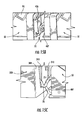
- FIG. 3B is the same as FIG. 3A , but showing the bend-insensitive cable fibers that connect the bend-insensitive fiber optic cable to the backside ports of the patch panel jacks;
- FIG. 3C is the same as FIG. 3B , but with the top panel in place and showing the angled connector for the bend-insensitive fiber optic cable;
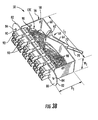
- FIG. 4 is a perspective view of an example embodiment of a mounting-frame-type patch panel assembly according to the present invention that has at least two mounting frames that each support an array of reduced-volume patch panel modules in a substantially vertical orientation;
- FIG. 5 is a perspective view similar to that of FIG. 4 illustrating an example embodiment of a mounting-frame-type patch panel assembly having dual-hinged front mounting frame;
- FIG. 6 is a perspective view similar to that of FIG. 5 , illustrating an example embodiment of a mounting-frame-type patch panel assembly having a single-hinged front mounting frame that folds downward, and also illustrating example reduced-volume patch panel modules of FIGS. 3A-3C having two bend-insensitive fiber optic cables connected to the backside thereof;
- FIG. 7 is a perspective view of a mounting-frame-type patch panel assembly similar to that of FIG. 4 , but illustrating an example embodiment wherein the back panel is in the form of a mounting frame that supports an array of rearward-facing reduced-volume patch panel modules;
- FIG. 8A is a perspective exploded view of an example embodiment of a front mounting frame and a housing portion that respectively include inner and outer curved hinge portions of a hinge assembly through which cables can be routed;
- FIG. 8B is a close-up top-down cross-sectional view of an example embodiment of the hinge assembly as formed from inner and outer curved hinge portions of the front patch panel mounting frame and the housing portion of FIG. 8A ;
- FIG. 9A is a perspective diagram of an example embodiment of a cable distribution box for guiding and/or storing bend-insensitive fiber optic cable;
- FIG. 9B is a perspective close-up view of an example cable distribution box FIG. 9A as arranged in a patch panel assembly behind a patch panel mounting frame;
- FIG. 9C is a perspective diagram of an example embodiment of a cable distribution box similar to that of FIG. 9A , but where the box has multiple chambers, no front apertures and two end apertures per chamber;
- FIG. 10A is a plan view of an example embodiment of a mounting-frame-type patch panel assembly that includes the hinge assembly shown in FIG. 8B as well as the cable distribution box as shown in FIG. 9A ;
- FIG. 10B is a plan view of the mounting-frame-type patch panel assembly of FIG. 10A and illustrates an example embodiment of how the cable fibers are routed from the rack frame to patch panel modules to the front mounting frame;
- FIG. 11A is a front perspective cut-away view of an example embodiment of drawer-type patch assembly that includes a drawer configured to hold patch panel modules horizontally with the jacks facing upward at an angle;
- FIG. 11B is a top-down front perspective view similar to that of FIG. 11A ;
- FIG. 11C is a top-down view of the drawer-type patch panel assembly of FIG. 11A , showing the drawer open and fiber optic cabling routed therein;
- FIG. 11D is similar to FIG. 11A but shows the drawer as closed and within the assembly housing;
- FIG. 12 is a rear perspective view of the drawer-type patch panel assembly similar to FIG. 11A , and that includes a patch panel module cover;
- FIGS. 13A through FIG. 13C are close-up perspective views of an example embodiment of a patch panel module for use in a drawer-type patch panel assembly, wherein the patch panel module includes an underside channel for cable routing;
- FIG. 14 is a close-up view of the array of patch panel modules of FIGS. 13A-13C as supported by the drawer floor panel in the drawer-type patch panel assembly, and showing a jumper cable connected to one of the module jacks;
- FIG. 15A is a side close-up view of the patch panel modules as mounted in the drawer such as shown in FIG. 12 , illustrating how the cable fibers are routed to the different patch panel modules via the underside channels;
- FIGS. 15B is a close-up view of adjacent front-row and back-row patch panel modules of FIG. 15A , illustrating how a cable fiber passes through the underside channel in the back-row module to be connected to the front-row module;
- FIGS. 15C is a close-up view of a back-row patch panel module and the adjacent cable distribution box of FIG. 15A , illustrating how a cable fiber passes from the cable distribution box to the adjacent patch panel module;
- FIG. 16 is a front perspective view of a number of drawer-type patch panel assemblies held in an equipment rack in a stacked manner
- FIG. 17 is a front perspective view of a number of mounting-frame-type patch panel assemblies held in an equipment rack in a stacked manner;
- FIG. 18A is an elevated rear perspective view of an example embodiment of a portion of a rack assembly shown supporting a single mounting-frame-type patch panel assembly similar to that shown in FIG. 10A ;
- FIG. 18B is another elevated rear perspective view of the rack assembly of FIG. 18A , but from the opposite quarter and with the back panel in place;
- FIG. 18C is an elevated front perspective view of the rack assembly of FIGS. 18A and 18B , showing details of how the cable fibers are routed to the patch panel modules on the front and intermediate mounting frames.
- Example embodiments of the present invention make use of bend-insensitive or "bend performance" fibers such as those in the form of so-called “nanostructure” or “holey” optical fibers.
- Nanostructure fibers have one or more regions with periodically or aperiodically arranged small holes or voids, which make the fiber extremely bend insensitive. Examples of such optical fibers are described in, for example, U.S. Pat. No. 6,243,522 , pending U.S. patent application serial number 11/583,098 filed October 18, 2006 (hereinafter, "the Corning nanostructure fiber patents and patent applications”), all of which are assigned to Coming Incorporated, and all of which are incorporated by reference herein.
- Bend-insensitive fibers as used in the present invention include, for example, nanostructure fibers of the type available from Corning, Inc., of Corning, NY, including, but not limited to, single-mode, multi-mode, bend performance fiber, bend-optimized fiber and bend-insensitive optical fiber. Nanostructure fibers are advantageous in that they allow for the patch panel modules and patch panel assemblies of the present invention to have fibers with relatively small-radius bends while optical attenuation in the fibers remains extremely low.
- a bend-insensitive optical fiber includes a core region and a cladding region surrounding the core region, the cladding region comprising an annular hole-containing region comprised of non-periodically disposed holes such that the optical fiber is capable of single mode transmission at one or more wavelengths in one or more operating wavelength ranges.
- the core region and cladding region provide improved bend resistance, and single mode operation at wavelengths preferably greater than or equal to 1500 nm, in some embodiments also greater than about 1310 nm, in other embodiments also greater than 1260 nm.
- the optical fibers provide a mode field at a wavelength of 1310 nm preferably greater than 8.0 ⁇ m, and more preferably between about 8.0 and 10.0 ⁇ m.
- One type of nanostructure optical fiber developed by Corning, Inc. has an annular ring of non-periodic airlines (of diameter ⁇ 1x10 -7 m) that extend longitudinally along the length of the fiber.
- the region with the ring of airlines has a reduced apparent or average index of refraction, because air has an index of refraction of approximately 1 compared to the fused silica matrix refractive index of approximately 1.46.
- the ring of airlines is positioned to create a refractive index profile that enables superior bend performance (optically) and significantly smaller minimum bend radius specifications.
- FIG. 1 is a schematic side view of a section of an example embodiment of a bend-insensitive fiber in the form of a nanostructure optical fiber ("nanostructure fiber") 12 having a central axis A F .
- FIG. 2A is a schematic cross-section of nanostructure fiber 12 as viewed along the direction 2A-2A in FIG. 1 .
- Nanostructure fiber 12 can be, for example, any one of the various types of nanostructure optical fibers, such as any of the so-called “holey” fibers, or those described in the above-mentioned Coming nanostructure fiber patents and patent applications.
- a "bend-insensitive fiber” includes nanostructure fibers that make use of periodic or non-periodic nanostructures or holes.
- nanostructure optical fiber 12 includes a core region ("core") 20, a nanostructure region 30 surrounding the core, and an outer cladding region 40 ("cladding") surrounding the nanostructure region.
- core core
- cladding outer cladding region
- Other ring-type configurations for nanostructure optical fiber 12 are also known.
- a protective cover or sheath optionally covers outer cladding 40.
- nanostructure region 30 comprises a glass matrix ("glass") 31 having formed therein non-periodically disposed holes (also called “voids” or “airlines”) 32, such as the example voids shown in detail in the magnified inset of FIG. 2A .
- voids 32 may be periodically disposed, such as in a photonic crystal optical fiber, wherein the voids typically have diameters between about 1x10 -6 m and 1x10 -5 m.
- Voids 32 may also be "non-periodic airlines.
- glass 31 is fluorine-doped while in another example embodiment the glass is undoped pure silica.
- non-periodically disposed or “non-periodic distribution,” it is meant that when one takes a cross-section of the optical fiber (such as shown in FIG. 2A ), the voids 32 are randomly or non-periodically distributed across a portion of the fiber.
- Cross sections similar to FIG. 2A taken at different points along the length of nanostructure optical fiber 12 will reveal different cross-sectional hole patterns, i.e., various cross-sections will have different hole patterns, wherein the distributions of holes and sizes of holes do not match. That is, the holes are non-periodic, i.e., they are not periodically disposed within the fiber structure. These holes are stretched (elongated) along the length (i.e. in a direction generally parallel to the longitudinal axis) of the optical fiber (and thus have a longer dimension along the length of the fiber), but do not extend the entire length of the entire fiber for typical lengths of transmission fiber. While not wishing to be bound by theory, it is believed that the holes extend less than a few meters, and in many cases less than 1 meter along the length of the fiber.
- non-periodically disposed holes/voids 32 are employed in nanostructure region 30 , it is desirable in one example embodiment that they be formed such that greater than 95% of and preferably all of the holes exhibit a mean hole size in the cladding for the optical fiber which is less than 1550 nm, more preferably less than 775 nm, most preferably less than about 390 nm. Likewise, it is preferable that the maximum diameter of the holes in the fiber be less than 7000 nm, more preferably less than 2000 nm, and even more preferably less than 1550 nm, and most preferably less than 775 nm.
- the fibers disclosed herein have fewer than 5000 holes, in some embodiments also fewer than 1000 holes, and in other embodiments the total number of holes is fewer than 500 holes in a given optical fiber perpendicular cross-section.
- the most preferred fibers will exhibit combinations of these characteristics.
- one particularly preferred embodiment of optical fiber would exhibit fewer than 200 holes in the optical fiber, the holes having a maximum diameter less than 1550 nm and a mean diameter less than 775 nm, although useful and bend resistant optical fibers can be achieved using larger and greater numbers of holes.
- the hole number, mean diameter, max diameter, and total void area percent of holes can all be calculated with the help of a scanning electron microscope at a magnification of about 800X to about 4000X and image analysis software, such as ImagePro, which is available from Media Cybernetics, Inc. of Silver Spring, Maryland, USA.
- holes/voids 32 can contain one or more gases, such as argon, nitrogen, or oxygen, or the holes can contain a vacuum with substantially no gas; regardless of the presence or absence of any gas, the refractive index of the hole-containing region is lowered due to the presence of the holes.
- the holes can be periodically or non-periodically disposed.
- the plurality of holes comprises a plurality of non-periodically disposed holes and a plurality of periodically disposed holes.
- the depressed index can also be provided by downdoping the glass in the hole-containing region (such as with fluorine) or updoping one or both of the surrounding regions.
- Nanostructure region 30 can be made by methods that utilize preform consolidation conditions, which are effective at trapping a significant amount of gases in the consolidated glass blank, thereby causing the formation of voids in the consolidated glass optical fiber preform. Rather than taking steps to remove these voids, the resultant preform is used to form an optical fiber with voids, or holes, therein.
- the diameter of a hole is the longest line segment whose end points are disposed on the silica internal surface defining the hole when the optical fiber is viewed in a perpendicular cross-section transverse to the optical fiber central axis A F .
- the nanostructure region comprised approximately 2.5 percent regional area percent holes (100% N 2 by volume) in that area with an average diameter of 0.28 ⁇ m and the smallest diameter holes at 0.17 ⁇ m and a maximum diameter of 0.48 ⁇ m, resulting in a total of about 130 holes in the fiber cross-section.
- the total fiber void area percent (area of the holes divided by total area of the optical fiber cross-section x 100) was about 0.05 percent.
- Optical properties for this fiber were 0.36 and 0.20 dB/Km at 1310 and 1550 nm, respectively, and a 22-meter fiber cable cut-off of about 1250 nm, thereby making the fiber single mode at wavelengths above 1250 nm.
- the nanostructure optical fibers as used herein may or may not include germania or fluorine to adjust the refractive index of the core and/or cladding of the optical fiber, but these dopants can also be avoided in the intermediate annular region and instead, the holes (in combination with any gas or gases that may be disposed within the holes) can be used to adjust the manner in which light is guided down the fiber core.
- the nanostructure region may consist of undoped (pure) silica, thereby completely avoiding the use of any dopants in the hole-containing region, to achieve a decreased refractive index, or the nanostructure region may comprise doped silica, e.g. fluorine-doped silica having a plurality of holes.
- the core includes doped silica to provide a positive refractive index relative to pure silica, e.g. germania doped silica.
- the core region is preferably hole-free.
- Such fiber can be made to exhibit a fiber cut-off of less than 1400 nm, more preferably less than 1310 nm, a 20-mm macrobend induced loss at 1550 nm of less than 1 dB/turn, preferably less than 0.5 dB/turn, even more preferably less than 0.1 dB/turn, still more preferably less than 0.05 dB/turn, yet more preferably less than 0.03 dB/turn, and even still more preferably less than 0.02 dB/turn, a 12-mm macrobend induced loss at 1550 nm of less than 5 dB/turn, preferably less than 1dB/turn, more preferably less than 0.5 dB/turn, even more preferably less than 0.2 dB/turn, still more preferably less than 0.1 dB/turn, still even more preferably less than 0.05 dB/turn, and an 8-mm macrobend induced loss at 1550 nm of less than 5 dB/turn, preferably less than 1
- the nanostructure fibers used herein may be multimode.
- Multimode optical fibers disclosed herein comprise a graded-index core region and a cladding region surrounding and directly adjacent to the core region, the cladding region comprising a depressed-index annular portion comprising a depressed relative refractive index relative to another portion of the cladding.
- the depressed-index annular portion of the cladding is preferably spaced apart from the core.
- the refractive index profile of the core has a parabolic shape.
- the depressed-index annular portion may, for example, comprise glass comprising a plurality of voids, or fluorine-doped glass, or fluorine-doped glass comprising a plurality of voids.
- the multimode optical fiber comprises a graded-index glass core; and a cladding surrounding and in contact with the core, the cladding comprising a depressed-index annular portion surrounding the core, said depressed-index annular portion having a refractive index delta less than about -0.2 % and a width of at least 1 micron, said depressed-index annular portion spaced from said core at least 0.5 microns.
- the multimode optical fiber disclosed herein exhibits very low bend induced attenuation, in particular very low macrobending induced attenuation.
- high bandwidth is provided by low maximum relative refractive index in the core, and low bend losses are also provided.
- the multimode optical fiber may comprise a graded-index glass core; and an inner cladding surrounding and in contact with the core, and a second cladding comprising a depressed-index annular portion surrounding the inner cladding, said depressed-index annular portion having a refractive index delta less than about -0.2 % and a width of at least 1 micron, wherein the width of said inner cladding is at least 0.5 microns and the fiber further exhibits a 1 turn 10 mm diameter mandrel wrap attenuation increase, of less than or equal to 0.4 dB/turn at 850 nm, a numerical aperture of greater than 0.18, and an overfilled bandwidth greater than 1.5 GHz-km at 850 nm.
- 50 micron diameter core multimode fibers can been made which provide (a) an overfilled (OFL) bandwidth of greater than 1.5 GHz-km, more preferably greater than 2.0 GHz-km, even more preferably greater than 3.0 GHz-km, and most preferably greater than 4.0 GHz-km at a wavelength of 850 nm.
- OFL overfilled
- These high bandwidths can be achieved while still maintaining a 1 turn 10 mm diameter mandrel wrap attenuation increase at a wavelength of 850 nm, of less than 0.5 dB, more preferably less than 0.3 dB, even more preferably less than 0.2 dB, and most preferably less than 0.15 dB.
- These high bandwidths can also be achieved while also maintaining a 1 turn 20 mm diameter mandrel wrap attenuation increase at a wavelength of 850 nm, of less than 0.2 dB, more preferably less than 0.1 dB, and most preferably less than 0.05 dB, and a 1 turn 15mm diameter mandrel wrap attenuation increase at a wavelength of 850 nm, of less than 0.2 dB, preferably less than 0.1 dB, and more preferably less than 0.05 dB.
- Such fibers are further capable of providing a numerical aperture (NA) greater than 0.17, more preferably greater than 0.18, and most preferably greater than 0.185.
- NA numerical aperture
- Such fibers are further simultaneously capable of exhibiting an OFL bandwidth at 1300nm which is greater than 500 MHz-km, more preferably greater than 600 MHz-km, even more preferably greater than 700 MHz-km.
- Such fibers are further simultaneously capable of exhibiting minimum calculated effective modal bandwidth (Min EMBc) bandwidth of greater than about 1.5 MHz-km, more preferably greater than about 1.8 MHz-km and most preferably greater than about 2.0 MHz-km at 850 nm.
- Min EMBc minimum calculated effective modal bandwidth
- the multimode optical fiber disclosed herein exhibits a spectral attenuation of less than 3 dB/km at 850 nm, preferably less than 2.5 dB/km at 850 nm, even more preferably less than 2.4 dB/km at 850 nm and still more preferably less than 2.3 dB/km at 850 nm.
- the multimode optical fiber disclosed herein exhibits a spectral attenuation of less than 1.0 dB/km at 1300 nm, preferably less than 0.8 dB/km at 1300 nm, even more preferably less than 0.6 dB/km at 1300 nm.
- spinning we mean applying or imparting a spin to the fiber wherein the spin is imparted while the fiber is being drawn from an optical fiber preform, i.e. while the fiber is still at least somewhat heated and is capable of undergoing non-elastic rotational displacement and is capable of substantially retaining the rotational displacement after the fiber has fully cooled.
- the numerical aperture (NA) of the optical fiber is preferably less than 0.23 and greater than 0.17, more preferably greater than 0.18, and most preferably less than 0.215 and greater than 0.185.
- the core extends radially outwardly from the centerline to a radius R1, wherein 20 ⁇ R1 ⁇ 40 microns. In some embodiments, 22 ⁇ R1 ⁇ 34 microns. In some preferred embodiments, the outer radius of the core is between about 22 to 28 microns. In some other preferred embodiments, the outer radius of the core is between about 28 to 34 microns.
- the core has a maximum relative refractive index, less than or equal to 1.2% and greater than 0.5%, more preferably greater than 0.8%. In other embodiments, the core has a maximum relative refractive index, less than or equal to 1.1 % and greater than 0.9%.
- the optical fiber exhibits a 1 turn 10 mm diameter mandrel attenuation increase of no more than 1.0 dB, preferably no more than 0.6 dB, more preferably no more than 0.4 dB, even more preferably no more than 0.2 dB, and still more preferably no more than 0.1 dB, at all wavelengths between 800 and 1400 nm.
- FIG. 2B is a schematic diagram illustrating a bend angle ⁇ B and a bend diameter D B of an example bend-insensitive optical fiber in the form of nanostructure fiber 12 having a bend formed therein.
- Bend diameter D B is twice the bend radius R B .
- Two arrows AR1 and AR2 represent the relative orientations (directions) of optical fiber 12 on either side of bend B.
- Bend angle ⁇ B is defined by the intersection of arrows AR1 and AR2, as shown in the right-hand side of FIG. 2B . Because sections of optical fiber do not always remain perfectly straight before and after a bend, the bend angle ⁇ B is not exact, but serves as a useful approximation that generally describes the degree to which nanostructure fiber 12 is bent.
- the bend-insensitive optical fibers used in the present invention have bends like bend B with a bend diameter D B as small as 10 mm. This, in part, allows for the patch panel modules of the present invention to be made relatively compact and to allow for the patch panel assemblies to contain a relatively high density of patch-panel modules and thus a high-density of jacks and ports for establishing optical connections.
- reference number 12 is used to refer to bend-insensitive fibers generally, with bend-insensitive "cable fibers" carried by a bend-insensitive fiber optic cable being identified as 12C to distinguish from bend-insensitive "jumper fibers,” which are identified as 12J.
- FIG. 3A is a perspective view of an example embodiment of a "reduced form factor" patch panel module 50 that includes a substantially rectangular module housing 56 having an interior 58 and a reduced form factor as compared to a standard patch panel module.
- Module housing 56 includes a backside wall 60 that has at least one V-shaped indentation 61 formed by first and second angled wall portions 62 and 64.
- Wall portion 62 includes an aperture (not shown) that allows a bend-insensitive fiber optic cable (“cable”) 70 that carries one or more cable fibers 12C to connected to the housing so that the cable fibers can be introduced into interior 58, as illustrated in FIG. 3B .
- cable bend-insensitive fiber optic cable
- cable 70 includes either twelve or twenty-four buffered cable fibers 12 (having, e.g., a diameter of 500 ⁇ m or 900 ⁇ m) or a 250 ⁇ m diameter bare fibers. Cable 70 preferably includes a boot 72 to support the fiber at its connection point at wall portion 62.
- Housing 56 also includes a front panel 80 having a number (e.g., twelve) spaced apart apertures (not shown) that hold a corresponding number (e.g., twelve) jacks 90.
- Front panel also includes respective ends 82 that have mounting holes 84 for mounting module 50 to panel mounting frames, introduced and described in greater detail below.
- FIG. 3C is the same as FIGS. 3A and 3B , but shows housing 56 having a cover 57 that encloses interior 58.
- Each jack 90 defines either one or two ports 92 open at a front side 96 and configured to receive a connectorized end 13J of a jumper fiber 12J.
- Each jack 90 also includes backside ports 98 where one or more cable fibers 12C from bend-insensitive fiber optic cable 70 are attached.
- module 50 includes two rows of six jacks 90, as shown. Further to the example embodiment, one or two cable fibers 12C are connected to each jack at back side ports 98 (i.e., one cable fiber for each port 92 ), as illustrated in FIG. 3B .
- Bend-insensitive cable fibers 12C also facilitate the connection of one or two cables 70 to patch panel module 50 at an angle relative to backside wall 60. This angled connection facilitates a high-density arrangement of patch panel modules 50 in a patch-panel assembly, as discussed in greater detail below.
- the angle 0 formed by cable 70 relative to the normal N to backside wall 60 is between about 60 degrees and 70 degrees, as shown in FIG. 3C .
- the use of one or two V-shaped indentations 61 serves to reduce the volume of interior 58 even further. This additional reduction in interior volume is also made possible by the use of bend-insensitive cable fibers 12C.
- FIG. 4 is a perspective view of example embodiment of a mounting-frame-type patch panel assembly 150.
- patch panel assembly 150 is configured to hold at least twenty-four patch panel modules 50 in a relatively high-density, substantially vertical configuration.
- a standard 4U shelf with twelve fully populated patch panel modules 50, there are 144 duplex jacks, or 288 ports.
- the example patch panel assembly 150 of FIG. 4 has two rows with 288 duplex jacks 90, for a total of 576 port 92. This is a "port/U" density of 144 ports/U because the patch panel assembly is assumed to be a standard "4U" shelf.
- a "triple-row" embodiment having three mounting frames 210 would have a 50% increase in port density, or 216 ports/U, which represents 864 individual fibers supported by the patch panel assembly 150, as compared to a standard patch panel assembly that supports 288 fibers.
- the port density is given by PD and is in the range defined by: 72 ports/U ⁇ PD ⁇ 216 ports/U.
- Patch panel assembly 150 includes a rectangular box-like housing 152 having a top 154 and bottom 155, a front 156 and a back panel or wall 157.
- Housing 152 includes spaced-apart sidewalls 160 that connect to back panel 157.
- Each sidewall 160 has an inside surface 162 and an outside surface 164, a front edge 166 and an opposite back edge 167.
- Housing 152 preferably includes outwardly extending mounting flanges 168 positioned on sidewall outer surfaces 164 at or near sidewall front edges 166.
- EIA-310-D Combints, Racks, Panels and Associated Equipment
- housing 152 includes a flat shelf 182 that connects sidewalls 160 at housing bottom 155 at front 156, and that extends beyond the sidewall front edges 166 at front 156.
- Shelf 182 has an upper surface 183, a front end 184 and a back end 185.
- front end 184 includes at least one hinge 196 that attaches a front cover 190 to frame 152 at front 156 so that the front cover folds downward.
- Front cover 190 has respective inner and outer surfaces 192 and 194.
- front cover 190 is transparent.
- Front cover optionally includes a clip 197 that is configured to engage an edge 199E of a clip plate 199 that is connected to interior mounting frame 210I and that extends over front mounting plate 210F.
- Housing 152 includes at least two mounting frames 210, and preferably includes a front mounting frame 210F and at least one interior mounting frame 210I that resided behind the front mounting frame and that spans interior region 200.
- Each mounting frame 210 has a bottom edge 211 and respective front and back sides or "faces" 212 and 214 and opposite ends 216.
- mounting frames 210 are connected to sidewalls 160 (e.g., at inside surface 162) at opposite ends 216.
- front mounting frame 210F is attached to front edges 166. Mounting frames 210 serve to divide the interior region into interior sub-regions 201.
- Each mounting frame front face 212 presents a mounting surface configured so that at least one and preferably more (e.g., preferably ten to twelve) patch panel modules 50 can be mounted thereto, e.g., at threaded holes 218 configured to correspond to mounting holes 84 of patch panel modules 50.
- one or more of the mounting frames 210 are made up of two sections 220, each of which are connected to respective sidewalls 160 via respective hinges 224 that allows the sections swing outwardly.
- front mounting frame 210F is shown as being made up of two sections. This geometry allows access to mounting panels 210 located immediately behind another mounting panel.
- one or more of mounting frames 210 are hinged on one side with one or more hinges 224 so that the entire hinged mounting frame swings open in door-like fashion.
- FIG. 6 illustrates an example embodiment of patch panel assembly 150 wherein front mounting frame 210F is attached to back end 185 of cross member 182 via a hinge 224 that allows the front mounting frame to fold downward.
- This configuration provides access to interior mounting frame 210I and patch panel modules 50 supported thereby that reside immediately behind the front mounting frame.
- This configuration also provides for easy access to cables 70 (not shown) that connect to patch panel modules 50 mounted front mounting frame 210F.
- the example embodiments shown in FIG. 5 and FIG. 6 show one internal mounting frame 210I; two or more internal mounting frames can also be employed.
- back panel 157 is hinged in the same manners as front mounting panel 210I in order to provide access to patch panel modules 50 mounted in the adjacent internal mounting frame 210I.
- FIG. 7 is a perspective view of an example patch panel assembly similar to that shown in FIG. 4 , but illustrating an example embodiment wherein the back panel 157 is in the form of a rear mounting frame 210R having a rearward-facing mounting face 214R that supports one or more (e.g., from one to twelve) rearward-facing patch panel modules 50.
- rear mounting frame 210R is configured in one of the hinged configurations as front mounting frame 210F described above and also as described below.
- mounting frames 210 are configured to support at least one patch panel module 50, and preferably is configured to support between 10 to 12 reduced-volume patch panel modules.
- An aspect of the present invention is directed to routing cables 70 to and from mounting-frame-type patch panel assembly 150, as well as managing the distribution of cables (including cable fibers 12C) within the patch panel assembly.
- FIG. 8A is a perspective exploded view of an example embodiment of front mounting frame 210F and a housing portion 152P.
- Front mounting frame 210F has a number of mounting apertures 213F in front face 212F for mounting patch panel modules 50.
- Front mounting frame 210F has a curved inner hinge portion 224I at one of the front mounting frame ends 216. Curved inner hinge portion 224I includes top and bottom surfaces 223 with vertically aligned holes 223H formed therein.
- Housing portion 152P includes a curved outer hinge portion 224O configured to partially surround curved inner hinge portion 224I when front mounting frame 210F and housing portion 152P are connected.
- Curved outer hinge portion 224O includes top and bottom surfaces 215 with vertically aligned holes 225H formed therein.
- Front mounting frame 210F and housing portion 152P are brought together so that curved inner portion 224I fits within curved outer portion 224O and so that holes 223H and 225H are aligned.
- a hinge pin PH is then passed through aligned holes 223H and 225H to operably fix curved inner and outer hinge portions 224I and 224O in place to form hinge assembly 224, wherein the curved inner hinge portion rotates within the curved outer hinge portion, while also serving to connect mounting frame 210F to housing portion 152P.
- FIG. 8B is a cross-sectional close-up view of an example embodiment of hinge assembly 224 as formed from curved inner and outer hinge portions 224I and 224O of FIG. 8A .
- the concave sides of curved inner and outer hinge portions 224I and 224O define a hinge interior space 224S that adds to housing interior region 200.
- Hinge interior space 224S serves as a conduit through which cables 70 pass when hinge assembly 224 is either in the closed position, as shown in FIG. 8B , or in the open position with front mounting frame 210F swung open.
- Hinge assembly 224 allows for opening and closing front mounting frame 210F without pinching the portions of cables 70 that pass through the hinge interior space 224S.
- hinge assembly 224 may include bushings (not shown) on surfaces 215 to facilitate the rotation of front mounting frame 210F. Hinge assembly 224 may also include a central cylindrical channel (not shown) that fits within the bushings and that accommodates hinge pin PH to facilitate smooth, reduced-friction operation of the hinge.
- FIG. 9A is a perspective diagram of an example embodiment of a cable distribution box or "stuff box" 300.
- Cable distribution box 300 is configured to receive cables 70 and distribute them to one or more patch panel modules 50, as described below.
- Cable distribution box 300 includes sides 302 having at least one aperture 304 formed therein and sized to pass a plurality of cables 70.
- Cable distribution box 300 also includes a substantially open top side 306, and front side 308 that has a plurality of V-shaped apertures 310 configured to align with corresponding patch panel modules 50.
- Cable distribution box 300 also includes an interior region or chamber 314 sized to accommodate multiple bend-insensitive fiber optic cables 70, including any slack therein.
- open topside 306 includes inwardly extending flexible tabs 312 that serve to keep cable 70 from unwinding, while providing easy access to the portion of the cable wound and stored within interior region 314.
- cable distribution box 300 is made from polymer, plastic or sheet metal.
- FIG. 9B is a perspective close-up view of an example cable distribution box 300 as arranged in patch panel assembly 150 behind a mounting frame 210 that supports patch panel modules 50.
- Multiple cables 70 are shown entering chamber 314 via aperture 304 in side 302, with a portion of the cables stored in looped fashion within the interior region.
- Some of cables 70 are shown exiting cable distribution box 300 through two of the front apertures 310 so that they can be connected to the backside 60 of the adjacent two patch panel modules 50.
- cable distribution box 300 is secured to patch panel assembly 150, e.g., at bottom 155 or to one of sidewalls 160.
- FIG. 9C is a perspective diagram of an example embodiment of a cable distribution box 300 similar to that of FIG. 9A , except that the box has multiple chambers 314 and no front apertures 310, and two end apertures 304 per chamber.
- FIG. 10A is a plan view of an example embodiment of mounting-frame-type patch panel assembly 150 that includes hinge assembly 224 of FIG. 8B as well as cable distribution box 300 of FIG. 9A arranged adjacent back wall 157.
- Patch panel assembly 150 includes on shelf upper surface 183, one or more clips 187 configured to guide and/or hold one or more cable fibers 12C or jump cables 12J onto the shelf surface (jump cables 12J are shown for illustration).
- cables 70 having portions thereof stored in cable distribution box 300 are connected to patch panel modules 50 of internal mounting frame 210I at respective patch panel module backsides 60. As indicated by arrows A 70 , other cables 70 are routed beneath internal mounting frame 210I along bottom 155 and through hinge assembly 224 and to the backsides 60 of patch panel modules 50 mounted in front mounting frame 210F.
- a floor panel FP is arranged adjacent bottom panel 155 and creates a "false floor" that defines a sub-region 323 to interior 200 sized to accommodate the routing of one or more cables 70.
- FIG. 10B is a plan view similar to FIG. 10A and illustrates an example embodiment of how cable fibers 12C (or jump fibers 12J) are routed from a rack frame 506 that supports patch panel assembly 150 to ports 90 on patch panel modules 50 on front mounting frame 210F and internal mounting frame 210I.
- some of cable fibers 12C or jump fibers 12J are held on shelf upper surface 183 using one or more clips 187.
- Sidewall 160 includes an aperture 160A formed therein that allows for cable fibers 12C from a main (e.g., trunk ) cable (not shown; see FIGS. 18A-18C ) to be routed into interior region 200 from rack frame 506.
- FIGS. 11A through 11D are top-down perspective cut-away views of an example embodiment of patch panel "drawer" assembly 150 held in a rack assembly 500.
- Patch panel assembly 150 includes a drawer 270 configured to hold one or more patch panel modules 50 in a high-density, substantially horizontal configuration, with jacks 90 facing upward but preferably angled toward the front of the drawer.
- FIGS. 11A through 11C shows drawer 270 pulled out from housing 152, while FIG. 11D shows the drawer slid into the housing.
- Housing 152 of patch panel assembly 150 includes a top panel 240, a bottom panel 242, and is open at front 156.
- One or both sidewalls 160 include one or more apertures 250 sized to pass one or more bend-insensitive cable fibers 12C.
- One or both sidewalls 160 also includes one or more apertures 256 sized to pass one or more jumper fibers 12J, as explained in greater detail below.
- drawer 270 is configured to clearance fit within interior 200 and to slide in and out thereof over bottom panel 242.
- drawer 270 has a floor panel 274 with a front end 276, a back end 278, and opposite side edges 280.
- Floor panel 274 supports an array of reduced-volume patch panel modules 50 arranged in one or more rows and in a horizontal configuration with jacks 90 pointing upward at an angle towards the front of drawer 270.
- drawer 270 obviates the need for vertically oriented module frames 210 as described above.
- Example patch panel modules 50 suitable for use in this configuration are discussed in greater detail below. Note that the backside walls 60 of the patch panel modules 50 are face-down on floor panel 274.
- each patch panel module 50 includes six jacks 90 each having one or two ports 92.
- the array of patch panel modules 50 is made up of two rows of eighteen modules, for a total of 36 modules and thus 216 jacks 90 and thus 216 or 432 ports 92, depending on whether the jacks are single or dual port.
- the drawer-type patch panel assembly 150 provides between 216 ports/U and 216 ports/U. Jacks 90 arranged on patch panel modules 50 at an angle relative to vertical and angled toward the front of drawer 270.
- housing assembly 150 further includes a cable distribution box 300 arranged near the back end 278 of floor panel 274 behind patch panel modules 50.
- cable distribution box 300 is configured to receive bend-insensitive fiber optic cables 70 and store a portion of them while distributing them to patch panel modules 50.
- housing bottom panel 242 includes at least one cable guide 350 configured to guide cables 70 that enter housing interior 200 from housing apertures 250.
- cable guide 350 includes at least one guide member 356.
- guide member 356 includes tray section 360 with sides 362.
- Guide member 356 may also include a number of spaced apart containment members 366 connected to respective sides so as to form an open tunnel-like channel 360 that contains one or more of cables 70.
- One end of guide member 356 is located at or near aperture 250, while the other end is located at back end 278 of drawer floor panel 274.
- cable guide 350 includes two articulated and curved guide members 356 that fold in and reside at housing back panel 157 in a stacked fashion when drawer 270 is closed, and that fold out and reside near housing sidewalls 160 when the drawer is opened. This folding action serves to control the distribution and bending of ⁇ fiber optic cables ⁇ being held within guide members 356.
- one guide member 356 is arranged at a different (e.g., lower) height than the other so that the lower guide member passes underneath the higher guide member when the two are folded together, as shown in FIG. 11D .
- FIG. 12 is a rear perspective view of patch panel assembly 150, wherein the assembly includes a drawer cover 390 that covers patch panel modules 50, wherein the drawer is shown in the open position. Also shown in FIG. 12 are the dimensions L 3 , H 3 and D 3 for housing 152.
- FIGS. 13A and 13B are perspective diagrams of an example embodiment of a patch panel module 50 suitable for use in the drawer-type patch panel assembly 150 of FIGS. 11A through 11D .
- the patch panel module 50 of the present example embodiment include housing 56, backside 60 and jacks 90 with ports 92.
- Patch panel module 50 of FIGS. 11A through 11D also have "reduced form factor.”
- Patch panel module 50 of the present example embodiment has a front 404 with angled facets 405, and ends 406 and 407. Note that each jack 90 is arranged on an angled facet 405 and are angled away from end 407.
- FIG. 13B shows cable fibers 12C from bend-insensitive fiber optic cable 70 attached to backside ports 98 of jacks 90.
- Patch panel module includes an open channel 420 formed in backside wall 60 and sized to accommodate cable 70 when patch-panel module 50 is placed with backside 60 against floor panel 274.
- FIG. 13C is a view of backside 60 of patch panel module 50 as would be seen by looking through floor panel 274 if the floor panel were transparent. Note that the cable 70 that attaches to patch panel module 50 of FIGS. 13A and 13B does so via end 407 of housing 56.
- FIG. 14 is a close-up view of an array of patch panel modules 50 of FIG. 13A as arranged on drawer floor panel 274.
- a jumper fiber 12J is shown connected to one of jacks 90.
- Cable 70 is also shown passing under one of the back-row patch panel modules 50 via channel 420 to the corresponding end 407 of the front row patch panel module.
- Cable fibers 12C from cable 70 are shown within one of the patch panel modules and connected to backside ports 98 of jacks 90 (see FIG. 13B ).
- FIG. 15A is close-up side view of drawer 270 and the array of patch panel modules 50 of FIG. 13A , showing in more detail how cables 70 passes from cable distribution box 300 and underneath the back-row patch panel modules 50 to the front-row patch panel modules. Other cables 70 are attached directly to the back-row patch panel modules 50 at respective housing ends 407.
- FIG. 15B is close-up view of adjacent back-row and front-row patch panel modules 50
- FIG. 15C is a close-up view of the back-row patch panel modules 50 and cable distribution box 300.
- These Figures illustrate the routing of respective cables 70 to a back row and a front row patch panel module 50.
- cable 70 is routed through channel 420 and emerges at side 406. This cable 70 is then connected to the adjacent patch panel module 50 at side 407.
- cable 70 emerges from an aperture 310 in cable distribution box 300 and is connected to end 407 of the adjacent patch panel module 50, while another cable 70 from aperture 310 is routed through channel 420 of the same patch panel module 50.
- aspects of the invention includes a rack assembly that houses either the drawer-type patch panel assemblies or mounting-frame-type patch panel assemblies described above. Because both of these types of patch panel assemblies 150 preferably have a standard 4U configuration, both can be housed in the same rack assembly.
- FIG. 16 is a front perspective view of an example embodiment of a rack assembly 500 that houses a number of drawer-type patch panel assemblies 150 in a stacked fashion.
- Rack assembly 500 includes rack frame 506 having vertical side bars 510 and 512, and a top horizontal cross-bar (not shown) that connects the side bars at the top of the frame.
- Vertical side bars 510 and 512 preferably have apertures 507 formed therein and sized to facilitate cable routing within frame 506.
- Frame 506 has a front side 518 and a backside 520.
- Frame 506 includes a flat base (not shown) to which side bars 510 and 512 are attached, and which serves to provide standing support for the frame.
- Frame assembly optionally includes a cable guide 513 attached to one or both of vertical side bars 510 and 512 to facilitate the routing of cables within the frame assembly.
- rack assembly 500 comprises a standard 19" equipment rack having an inside width of 17.75", on-center rail hole pairs separated by 18.3" on the front of the rack, and is divided up by standard 1.75" increments, where each increment is called a "unit" or "U” for short and includes three complete hole pairs.
- Frame 506 defines an interior region 530 within which patch panel assemblies 150 reside.
- Drawers 270 of the drawer-type patch panel assemblies 150 preferably include handles 550.
- FIG. 17 is a front perspective view an example embodiment of rack assembly 500 similar to that of FIG. 16 , but showing a number of mounting-frame-type patch panel assemblies 150 housed in an equipment rack assembly 500 in a stacked manner.
- side bars 510 and 512 are configure to allow for patch panel assemblies 150 to be arranged in a stacked manner between the side bars and thus within frame interior region 530, as shown.
- the inside surface of side bars 510 and 512 are smooth, while in another example embodiment they include guide tabs (not shown) that facilitate the stacking and support of housing assemblies 150 within frame 506.
- side bars 510 and 512 are configured so that front and back portions of the patch panel assemblies protrude from the front side 518 and backside 520 of frame 506, as illustrated in FIGS. 16 and 17 .
- FIG. 18A is a elevated rear perspective view of an example embodiment of a portion of rack assembly 500 shown supporting a single mounting-frame-type patch panel assembly 150 similar to that shown in FIG. 10A .
- Rack assembly 500 includes a main (e.g., trunk) cable 602 that carries a plurality of optical fibers, such as cables 70.
- main cable 602 includes a boot 610 that leads to a fan-out section 620. Cables 70 in main cable 620 are then connected to a plurality of connector ports 626 at housing side 160.
- "external" cables 70 are connected to "internal” cables 70 of patch panel assembly 150 at connector ports 626.
- Internal cables 70 are shown as having connectorized ends 73 for connecting to connector ports 626.
- Internal cables 70 are routed through cable distribution box 300. Some internal cables 70 are connected to backsides 60 of patch panel modules 50 mounted in an interior mounting frame 210I . Other internal cables are routed to patch panel modules on front mounting frame 210F, which is shown in the open position.
- front mounting frame 210F includes a guide shelf 215 that extends inwardly toward interior region 200 from bottom edge 211. Guide shelf 215 is configured to guide and/or hold cables 70 that are routed to patch panel modules 50 mounted in front mounting frame 210F.
- guide shelf 215 includes clips 185 that serve to guide and/or hold cables 70 on the guide shelf. It should be noted again that in FIG. 18B cables 70 and 12C can be the same type of cables, e.g., patch cables or jump cables ( 12J ).
- FIG. 18B is another elevated rear perspective view of rack assembly 500 of FIG. 18A but from the opposite quarter and with back wall 157 in place.
- a bundle of cable fibers 12C (which could also be jump cables 12J ) and main cable 602 are shown being routed through apertures 507 in adjacent rack frames 506 (see FIG. 10B ).
- FIG. 18C is an elevated front perspective view of rack assembly 500 of FIGS. 18A and 18B , showing details of how cable fibers 12C (or jump fibers 12J ) are routed to patch panel assemblies 50 on the front and intermediate mounting frames 210F and 210I.
- Clips 185 on cross member 182 are used to guide cable fibers 12C or jump fibers 12J from rack frame 506 to patch panel assemblies 50 supported by front mounting frame 210F.
- Clips 185 are also provided between front and internal mounting frames 210F and 210I to assist in guiding cable fibers 12C or jump fibers 12J from rack frame 506 to patch panel modules 50 supported by internal mounting frame 210I.
Applications Claiming Priority (1)
| Application Number | Priority Date | Filing Date | Title |
|---|---|---|---|
| US12/231,376 US7856166B2 (en) | 2008-09-02 | 2008-09-02 | High-density patch-panel assemblies for optical fiber telecommunications |
Publications (2)
| Publication Number | Publication Date |
|---|---|
| EP2159617A2 true EP2159617A2 (de) | 2010-03-03 |
| EP2159617A3 EP2159617A3 (de) | 2013-01-09 |
Family
ID=41463120
Family Applications (1)
| Application Number | Title | Priority Date | Filing Date |
|---|---|---|---|
| EP09010956A Withdrawn EP2159617A3 (de) | 2008-09-02 | 2009-08-27 | Stecktafelanordnung mit hoher Dichte für die Glasfasertelekommunikation |
Country Status (4)
| Country | Link |
|---|---|
| US (2) | US7856166B2 (de) |
| EP (1) | EP2159617A3 (de) |
| JP (1) | JP2010061143A (de) |
| AU (1) | AU2009212777A1 (de) |
Cited By (16)
| Publication number | Priority date | Publication date | Assignee | Title |
|---|---|---|---|---|
| WO2012069084A1 (en) * | 2010-11-25 | 2012-05-31 | Prysmian S.P.A. | Optical box |
| ITRM20110473A1 (it) * | 2011-09-09 | 2013-03-10 | Cis Sud Srl | Permutatore ottico ad alta densità. |
| US8873925B2 (en) | 2010-06-03 | 2014-10-28 | Genia Photonics Inc. | Fiber optic hinge |
| WO2014174539A1 (en) * | 2013-04-24 | 2014-10-30 | Prysmian S.P.A. | User module and method for connecting an external communication network |
| WO2015196577A1 (zh) * | 2014-06-26 | 2015-12-30 | 中兴通讯股份有限公司 | 智能控制装置、智能光分配网络设备及系统 |
| WO2016042032A1 (en) * | 2014-09-16 | 2016-03-24 | Tyco Electronics Raychem Bvba | Telecommunications tray with a cable routing path extending through a pivot hinge |
| US10025055B2 (en) | 2014-09-16 | 2018-07-17 | CommScope Connectivity Belgium BVBA | Multi-positionable telecommunications tray |
| US10175440B2 (en) | 2013-03-19 | 2019-01-08 | Adc Czech Republic, S.R.O. | Moveable bend control and patch cord support for telecommunications panel |
| US10254496B2 (en) | 2015-04-23 | 2019-04-09 | CommScope Connectivity Belgium BVBA | Telecommunications panel assembly with movable adapters |
| USD865696S1 (en) * | 2018-06-07 | 2019-11-05 | Fiberstore Co., Limited | Ultra high density fiber enclosure |
| USD865697S1 (en) * | 2018-06-07 | 2019-11-05 | Fiberstore Co., Limited | Ultra high density fiber enclosure |
| US10502917B2 (en) | 2014-09-16 | 2019-12-10 | CommScope Connectivity Belgium BVBA | Telecommunications tray assembly |
| USD887377S1 (en) * | 2018-06-07 | 2020-06-16 | Fiberstore Co., Limited | Ultra high density fiber enclosure |
| CN112689207A (zh) * | 2019-10-18 | 2021-04-20 | 罗森伯格高频技术有限及两合公司 | 接线板和配线架 |
| KR102244543B1 (ko) * | 2021-01-19 | 2021-04-26 | (주)부흥이앤씨 | 건물용 정보통신 슬림형 광분배함 |
| US11175469B2 (en) | 2017-10-26 | 2021-11-16 | CommScope Connectivity Belgium BVBA | Telecommunications system |
Families Citing this family (125)
| Publication number | Priority date | Publication date | Assignee | Title |
|---|---|---|---|---|
| JP4891162B2 (ja) * | 2007-06-29 | 2012-03-07 | キヤノン株式会社 | 画像処理装置ならびにプロファイル作成方法 |
| US11294135B2 (en) | 2008-08-29 | 2022-04-05 | Corning Optical Communications LLC | High density and bandwidth fiber optic apparatuses and related equipment and methods |
| US8452148B2 (en) | 2008-08-29 | 2013-05-28 | Corning Cable Systems Llc | Independently translatable modules and fiber optic equipment trays in fiber optic equipment |
| EP2221932B1 (de) | 2009-02-24 | 2011-11-16 | CCS Technology Inc. | Haltevorrichtung für ein Kabel oder eine Anordnung zur Verwendung mit einem Kabel |
| US8699838B2 (en) | 2009-05-14 | 2014-04-15 | Ccs Technology, Inc. | Fiber optic furcation module |
| US8538226B2 (en) | 2009-05-21 | 2013-09-17 | Corning Cable Systems Llc | Fiber optic equipment guides and rails configured with stopping position(s), and related equipment and methods |
| US9075216B2 (en) | 2009-05-21 | 2015-07-07 | Corning Cable Systems Llc | Fiber optic housings configured to accommodate fiber optic modules/cassettes and fiber optic panels, and related components and methods |
| WO2010148336A1 (en) | 2009-06-19 | 2010-12-23 | Corning Cable Systems Llc | High density and bandwidth fiber optic apparatuses and related equipment and methods |
| EP2443498B1 (de) * | 2009-06-19 | 2020-06-24 | Corning Optical Communications LLC | Vorrichtung mit hoher glasfaserkabelbündelungsdichte |
| US8712206B2 (en) | 2009-06-19 | 2014-04-29 | Corning Cable Systems Llc | High-density fiber optic modules and module housings and related equipment |
| US8625950B2 (en) | 2009-12-18 | 2014-01-07 | Corning Cable Systems Llc | Rotary locking apparatus for fiber optic equipment trays and related methods |
| US8593828B2 (en) | 2010-02-04 | 2013-11-26 | Corning Cable Systems Llc | Communications equipment housings, assemblies, and related alignment features and methods |
| US8913866B2 (en) | 2010-03-26 | 2014-12-16 | Corning Cable Systems Llc | Movable adapter panel |
| EP2558895B1 (de) | 2010-04-16 | 2019-04-17 | Corning Optical Communications LLC | Dichtungs- und zugentlastungsvorrichtung für datenkabel |
| EP2381284B1 (de) | 2010-04-23 | 2014-12-31 | CCS Technology Inc. | Glasfaserverteilungsvorrichtung für Unterboden |
| US8879881B2 (en) | 2010-04-30 | 2014-11-04 | Corning Cable Systems Llc | Rotatable routing guide and assembly |
| US8705926B2 (en) | 2010-04-30 | 2014-04-22 | Corning Optical Communications LLC | Fiber optic housings having a removable top, and related components and methods |
| US9075217B2 (en) | 2010-04-30 | 2015-07-07 | Corning Cable Systems Llc | Apparatuses and related components and methods for expanding capacity of fiber optic housings |
| US9632270B2 (en) | 2010-04-30 | 2017-04-25 | Corning Optical Communications LLC | Fiber optic housings configured for tool-less assembly, and related components and methods |
| US9720195B2 (en) * | 2010-04-30 | 2017-08-01 | Corning Optical Communications LLC | Apparatuses and related components and methods for attachment and release of fiber optic housings to and from an equipment rack |
| US8660397B2 (en) | 2010-04-30 | 2014-02-25 | Corning Cable Systems Llc | Multi-layer module |
| US9519118B2 (en) | 2010-04-30 | 2016-12-13 | Corning Optical Communications LLC | Removable fiber management sections for fiber optic housings, and related components and methods |
| CA2799225C (en) * | 2010-05-14 | 2016-10-11 | Afl Telecommunications Llc | Fiber optic cable management module and panel |
| US8718436B2 (en) | 2010-08-30 | 2014-05-06 | Corning Cable Systems Llc | Methods, apparatuses for providing secure fiber optic connections |
| US9279951B2 (en) | 2010-10-27 | 2016-03-08 | Corning Cable Systems Llc | Fiber optic module for limited space applications having a partially sealed module sub-assembly |
| US9116324B2 (en) | 2010-10-29 | 2015-08-25 | Corning Cable Systems Llc | Stacked fiber optic modules and fiber optic equipment configured to support stacked fiber optic modules |
| US8662760B2 (en) | 2010-10-29 | 2014-03-04 | Corning Cable Systems Llc | Fiber optic connector employing optical fiber guide member |
| AU2011336747A1 (en) | 2010-11-30 | 2013-06-20 | Corning Cable Systems Llc | Fiber device holder and strain relief device |
| US20120183004A1 (en) * | 2010-12-13 | 2012-07-19 | Redfern Integrated Optics, Inc. | Ultra-Low Frequency-Noise Semiconductor Laser With Electronic Frequency Feedback Control and Homodyne Optical Phase Demodulation |
| CN103403594B (zh) | 2011-02-02 | 2016-11-23 | 康宁光缆系统有限责任公司 | 适用于为设备机架中的光学底板建立光学连接的稠密的光阀遮蔽的光纤连接器及总成 |
| US9008485B2 (en) | 2011-05-09 | 2015-04-14 | Corning Cable Systems Llc | Attachment mechanisms employed to attach a rear housing section to a fiber optic housing, and related assemblies and methods |
| US8989547B2 (en) | 2011-06-30 | 2015-03-24 | Corning Cable Systems Llc | Fiber optic equipment assemblies employing non-U-width-sized housings and related methods |
| EP2544035A1 (de) * | 2011-07-07 | 2013-01-09 | 3M Innovative Properties Company | Glasfaserverteilungsvorrichtung |
| US8953924B2 (en) | 2011-09-02 | 2015-02-10 | Corning Cable Systems Llc | Removable strain relief brackets for securing fiber optic cables and/or optical fibers to fiber optic equipment, and related assemblies and methods |
| US9229172B2 (en) | 2011-09-12 | 2016-01-05 | Commscope Technologies Llc | Bend-limited flexible optical interconnect device for signal distribution |
| US9417418B2 (en) | 2011-09-12 | 2016-08-16 | Commscope Technologies Llc | Flexible lensed optical interconnect device for signal distribution |
| US9100208B2 (en) | 2011-09-27 | 2015-08-04 | Hubbell Incorporated | Method and apparatus for circuit emulation with integrated network diagnostics and reduced form factor in large public communication networks |
| EP2764390B1 (de) | 2011-10-07 | 2020-12-02 | CommScope Technologies LLC | Glasfaserkassette sowie system und verfahren dafür |
| US9170391B2 (en) | 2011-10-07 | 2015-10-27 | Adc Telecommunications, Inc. | Slidable fiber optic connection module with cable slack management |
| US9069150B2 (en) | 2011-10-07 | 2015-06-30 | Adc Telecommunications, Inc. | Slidable fiber optic connection module with cable slack management |
| US9002166B2 (en) | 2011-10-07 | 2015-04-07 | Adc Telecommunications, Inc. | Slidable fiber optic connection module with cable slack management |
| US9097872B2 (en) | 2011-11-08 | 2015-08-04 | Optical Cable Corporation | High density telecommunications patching system and cassettes |
| CN103105653A (zh) * | 2011-11-14 | 2013-05-15 | 上海邮电设计咨询研究院有限公司 | 一种用于三网融合光纤接入的住户信息配线箱 |
| US9038832B2 (en) | 2011-11-30 | 2015-05-26 | Corning Cable Systems Llc | Adapter panel support assembly |
| US9075203B2 (en) | 2012-01-17 | 2015-07-07 | Adc Telecommunications, Inc. | Fiber optic adapter block |
| US8620123B2 (en) | 2012-02-13 | 2013-12-31 | Corning Cable Systems Llc | Visual tracer system for fiber optic cable |
| US9361600B2 (en) | 2012-02-14 | 2016-06-07 | Tyco Electronics Uk Ltd | Physical layer management (PLM) system for use with an optical distribution frame in which trays can be selectively removed and re-attached |
| US8964374B1 (en) | 2012-02-28 | 2015-02-24 | Google Inc. | Vertical tray structure for rack in data center |
| TWI487963B (zh) | 2012-04-08 | 2015-06-11 | Hon Hai Prec Ind Co Ltd | 面層電路互聯系統組件 |
| JP5897982B2 (ja) * | 2012-05-10 | 2016-04-06 | 本田技研工業株式会社 | 燃料電池システム |
| US9250409B2 (en) | 2012-07-02 | 2016-02-02 | Corning Cable Systems Llc | Fiber-optic-module trays and drawers for fiber-optic equipment |
| US9042702B2 (en) | 2012-09-18 | 2015-05-26 | Corning Cable Systems Llc | Platforms and systems for fiber optic cable attachment |
| US10082636B2 (en) | 2012-09-21 | 2018-09-25 | Commscope Technologies Llc | Slidable fiber optic connection module with cable slack management |
| US9195021B2 (en) | 2012-09-21 | 2015-11-24 | Adc Telecommunications, Inc. | Slidable fiber optic connection module with cable slack management |
| WO2014049361A1 (en) | 2012-09-27 | 2014-04-03 | Tyco Electronics Uk Ltd. | Mobile application for assisting a technician in carrying out an electronic work order |
| CN104838301B (zh) | 2012-09-28 | 2017-06-09 | 泰科电子英国有限公司 | 光纤盒 |
| US9146374B2 (en) | 2012-09-28 | 2015-09-29 | Adc Telecommunications, Inc. | Rapid deployment packaging for optical fiber |
| EP2901191A4 (de) | 2012-09-28 | 2016-10-26 | Tyco Electronics Ltd Uk | Herstellung und testen einer glasfaserkassette |
| US9223094B2 (en) | 2012-10-05 | 2015-12-29 | Tyco Electronics Nederland Bv | Flexible optical circuit, cassettes, and methods |
| ES2551077T3 (es) | 2012-10-26 | 2015-11-16 | Ccs Technology, Inc. | Unidad de gestión de fibra óptica y dispositivo de distribución de fibra óptica |
| US9130318B2 (en) | 2012-11-16 | 2015-09-08 | Tyco Electronics Uk Ltd. | Localized reading of RFID tags located on multiple sides of a port from a single side using RFID coupling circuit and portable RFID reader |
| AU2014211445B2 (en) | 2013-01-29 | 2017-07-13 | CommScope Connectivity Belgium BVBA | Optical fiber distribution system |
| US9128262B2 (en) | 2013-02-05 | 2015-09-08 | Adc Telecommunications, Inc. | Slidable telecommunications tray with cable slack management |
| US9389384B2 (en) | 2013-02-27 | 2016-07-12 | Commscope Technologies Llc | Slidable fiber optic connection module with cable slack management |
| US8985862B2 (en) * | 2013-02-28 | 2015-03-24 | Corning Cable Systems Llc | High-density multi-fiber adapter housings |
| US9435975B2 (en) | 2013-03-15 | 2016-09-06 | Commscope Technologies Llc | Modular high density telecommunications frame and chassis system |
| US9170386B2 (en) | 2013-04-08 | 2015-10-27 | Hon Hai Precision Industry Co., Ltd. | Opto-electronic device assembly |
| US9541726B2 (en) | 2013-04-24 | 2017-01-10 | Adc Czech Republic, S.R.O. | Optical fiber distribution system |
| EP2989496B1 (de) | 2013-04-24 | 2019-06-12 | CommScope Connectivity Belgium BVBA | Universeller befestigungsmechanismus für die befestigung eines telekommunikationsgehäuses an einer telekommunikationshalterung |
| US9123111B2 (en) | 2013-08-15 | 2015-09-01 | Xerox Corporation | Methods and systems for detecting patch panel ports from an image in which some ports are obscured |
| US9407510B2 (en) | 2013-09-04 | 2016-08-02 | Commscope Technologies Llc | Physical layer system with support for multiple active work orders and/or multiple active technicians |
| EP3100090A4 (de) | 2014-01-28 | 2017-09-06 | ADC Telecommunications Inc. | Verschiebbares glasfaser-verbindungsmodul mit kabelüberlängenverwaltung |
| CN106461877A (zh) * | 2014-03-26 | 2017-02-22 | 泰科电子公司 | 具有受管理的连接性的光学适配器模块 |
| US9494758B2 (en) | 2014-04-03 | 2016-11-15 | Commscope Technologies Llc | Fiber optic distribution system |
| US9690065B2 (en) | 2014-09-12 | 2017-06-27 | Panduit Corp. | High density fiber enclosure and method |
| US10379309B2 (en) | 2014-11-18 | 2019-08-13 | Corning Optical Communications LLC | Traceable optical fiber cable and filtered viewing device for enhanced traceability |
| EP3230780B1 (de) | 2014-12-10 | 2023-10-25 | CommScope Technologies LLC | Verwaltungsmodul für faseroptische kabelüberlängen |
| US10228526B2 (en) | 2015-03-31 | 2019-03-12 | Corning Optical Communications LLC | Traceable cable with side-emitting optical fiber and method of forming the same |
| WO2016156611A1 (en) | 2015-04-03 | 2016-10-06 | CommScope Connectivity Belgium BVBA | Telecommunications distribution elements |
| US10101553B2 (en) | 2015-05-20 | 2018-10-16 | Corning Optical Communications LLC | Traceable cable with side-emitting optical fiber and method of forming the same |
| WO2017015084A1 (en) | 2015-07-17 | 2017-01-26 | Corning Optical Communications LLC | Systems and methods for traceable cables |
| CN107850737A (zh) | 2015-07-17 | 2018-03-27 | 康宁光电通信有限责任公司 | 用于跟踪电缆的系统和方法以及用于此类系统和方法的电缆 |
| US10101545B2 (en) | 2015-10-30 | 2018-10-16 | Corning Optical Communications LLC | Traceable cable assembly and connector |
| WO2017089463A1 (en) | 2015-11-25 | 2017-06-01 | CommScope Connectivity Belgium BVBA | Fiber management for pivotable trays |
| KR200486227Y1 (ko) | 2016-03-16 | 2018-04-17 | 엘에스산전 주식회사 | 모터 컨트롤 센터 유닛 |
| EP3440488A1 (de) | 2016-04-08 | 2019-02-13 | Corning Optical Communications LLC | Kabelanordnung mit verfolgbarem endpunkt |
| US9817201B2 (en) | 2016-04-12 | 2017-11-14 | Ciena Corporation | Sliding assembly and method for fiber management |
| EP3446554B1 (de) | 2016-04-19 | 2020-12-02 | CommScope, Inc. of North Carolina | Telekommunikationschassis mit verschiebbaren schalen |
| WO2017184501A1 (en) | 2016-04-19 | 2017-10-26 | Commscope, Inc. Of North Carolina | Door assembly for a telecommunications chassis with a combination hinge structure |
| US10107983B2 (en) | 2016-04-29 | 2018-10-23 | Corning Optical Communications LLC | Preferential mode coupling for enhanced traceable patch cord performance |
| US10215944B2 (en) | 2016-06-30 | 2019-02-26 | Panduit Corp. | Modular fiber optic tray |
| KR102608994B1 (ko) | 2016-07-28 | 2023-12-06 | 삼성전자주식회사 | 생체 인증을 이용한 결제 방법 및 이를 수행하는 전자 장치 |
| CN109906395B (zh) | 2016-09-08 | 2021-06-18 | 康普连通比利时私人有限公司 | 电信分配元件 |
| US10222560B2 (en) | 2016-12-21 | 2019-03-05 | Corning Research & Development Corporation | Traceable fiber optic cable assembly with fiber guide and tracing optical fibers for carrying light received from a light launch device |
| US10234614B2 (en) | 2017-01-20 | 2019-03-19 | Corning Research & Development Corporation | Light source assemblies and systems and methods with mode homogenization |
| WO2018187459A1 (en) | 2017-04-04 | 2018-10-11 | Commscope Technologies Llc | Optical splice and termination module |
| US11215767B2 (en) | 2017-06-07 | 2022-01-04 | Commscope Technologies Llc | Fiber optic adapter and cassette |
| US10670822B2 (en) | 2017-06-28 | 2020-06-02 | Afl Telecommunications Llc | High density patch panel with modular cassettes |
| CN111164479B (zh) | 2017-10-02 | 2021-11-19 | 康普技术有限责任公司 | 光纤光学电路和制备方法 |
| US11385429B2 (en) | 2017-10-18 | 2022-07-12 | Commscope Technologies Llc | Fiber optic connection cassette |
| US10539758B2 (en) | 2017-12-05 | 2020-01-21 | Corning Research & Development Corporation | Traceable fiber optic cable assembly with indication of polarity |
| US10539747B2 (en) | 2017-12-05 | 2020-01-21 | Corning Research & Development Corporation | Bend induced light scattering fiber and cable assemblies and method of making |
| US10555055B2 (en) * | 2017-12-29 | 2020-02-04 | Nexans | Patch panels for use with fiber optic and copper cables and support rack for the same |
| US11039224B2 (en) | 2018-01-03 | 2021-06-15 | Infinera Corporation | Telecommunication appliance having high density embedded pluggable optics |
| JP6731009B2 (ja) * | 2018-02-15 | 2020-07-29 | 株式会社フジクラ | 光配線ユニット、光配線ユニット付きラック及び光配線ユニット付きラックの製造方法 |
| EP3759535A4 (de) | 2018-02-28 | 2021-11-10 | CommScope Technologies LLC | Gehäuseanordnung für telekommunikationsausrüstung |
| US10416406B1 (en) * | 2018-03-01 | 2019-09-17 | Afl Telecommunications Llc | Communications module housing |
| US11169340B2 (en) * | 2018-03-21 | 2021-11-09 | Foxconn (Kunshan) Computer Connector Co., Ltd. | Interconnection system |
| US11256054B2 (en) | 2018-04-16 | 2022-02-22 | Commscope Technologies Llc | Adapter structure |
| WO2019201878A1 (en) | 2018-04-17 | 2019-10-24 | CommScope Connectivity Belgium BVBA | Telecommunications distribution elements |
| DK3844972T3 (da) | 2018-08-31 | 2022-10-17 | CommScope Connectivity Belgium BVBA | Rammesamlinger til optiske fiberfordelingselementer |
| EP3844547A1 (de) | 2018-08-31 | 2021-07-07 | CommScope Connectivity Belgium BVBA | Rahmenanordnungen für glasfaserverteilungselemente |
| EP3845044B1 (de) | 2018-08-31 | 2023-02-15 | CommScope Connectivity Belgium BVBA | Rahmenanordnungen für optische faserverteilungselemente |
| EP3844973A1 (de) | 2018-08-31 | 2021-07-07 | CommScope Connectivity Belgium BVBA | Rahmenanordnungen für optische faserverteilungselemente |
| US10451828B1 (en) | 2018-11-09 | 2019-10-22 | Afl Telecommunications Llc | Communications module housing |
| EP3914947A1 (de) | 2019-01-25 | 2021-12-01 | CommScope Connectivity Belgium BVBA | Rahmenanordnungen für optische faserverteilungselemente |
| MX2021012546A (es) | 2019-04-17 | 2021-11-12 | Afl Ig Llc | Panel de conexion con remocion de casete elevador. |
| US11258240B1 (en) * | 2019-07-11 | 2022-02-22 | James C. White Company, Inc. | Cable guides for use with cable trays |
| US11243366B2 (en) | 2019-12-16 | 2022-02-08 | Afl Telecommunications Llc | Rack routing guide |
| KR102171084B1 (ko) * | 2020-06-19 | 2020-10-29 | (주)삼우공간건축사사무소 | 초고속 정보통신 건물용 광분배함 |
| EP4214081A1 (de) | 2020-09-18 | 2023-07-26 | Nubis Communications, Inc. | Datenverarbeitungssystem mit optischen kommunikationsmodulen |
| KR102315612B1 (ko) * | 2021-01-27 | 2021-10-21 | 주식회사 청림이앤씨 | 조립이 용이한 광어댑터 패널이 구비된 광케이블 단자함 |
| EP4356175A1 (de) * | 2021-06-17 | 2024-04-24 | Nubis Communications, Inc. | Kommunikationssysteme mit steckbaren modulen |
| US11595145B1 (en) * | 2021-09-02 | 2023-02-28 | Dell Products L.P. | High-density switch |
| US11719899B2 (en) * | 2021-09-02 | 2023-08-08 | Dell Products L.P. | High-density co-packaged optics networking system |
Citations (1)
| Publication number | Priority date | Publication date | Assignee | Title |
|---|---|---|---|---|
| US6243522B1 (en) | 1998-12-21 | 2001-06-05 | Corning Incorporated | Photonic crystal fiber |
Family Cites Families (115)
| Publication number | Priority date | Publication date | Assignee | Title |
|---|---|---|---|---|
| DE3838428A1 (de) | 1988-11-12 | 1990-05-31 | Philips Patentverwaltung | Schaltverteiler zur herstellung von frei waehlbaren optischen steckverbindungen |
| US4911662A (en) | 1988-12-20 | 1990-03-27 | Northern Telecom Limited | Distribution frame for telecommunications cable |
| US5071211A (en) | 1988-12-20 | 1991-12-10 | Northern Telecom Limited | Connector holders and distribution frame and connector holder assemblies for optical cable |
| FR2646928B1 (fr) | 1989-05-11 | 1993-12-24 | Etat Francais Cnet | Module et boitier de raccordement de cables a fibres optiques |
| US5067784A (en) | 1990-11-19 | 1991-11-26 | George Debortoli | Connector holders |
| US5127082A (en) | 1991-03-22 | 1992-06-30 | The Siemon Company | Fiber optic patch panel |
| US5129030A (en) | 1991-05-30 | 1992-07-07 | At&T Bell Laboratories | Movable lightguide connector panel |
| US5167001A (en) | 1991-09-03 | 1992-11-24 | Northern Telecom Limited | Optical fiber storage and connector tray and shelf and tray assembly |
| US5204929A (en) | 1991-09-04 | 1993-04-20 | Reliance Comm/Tec Corporation | Fiber patch panel |
| US5209572A (en) | 1991-11-08 | 1993-05-11 | Accuride International, Inc. | Thin drawer slide |
| US5243679A (en) | 1992-02-07 | 1993-09-07 | Gv Medical, Inc. | Optical fiber advancement, retraction and storage system |
| US5401193A (en) | 1993-02-10 | 1995-03-28 | Lo Cicero; Rae-Ann | Patch panel system |
| US5339379A (en) | 1993-06-18 | 1994-08-16 | Telect, Inc. | Telecommunication fiber optic cable distribution apparatus |
| US5412751A (en) * | 1993-08-31 | 1995-05-02 | The Siemon Company | Retrofittable multimedia patch management system |
| US5398295A (en) | 1993-09-08 | 1995-03-14 | Chang; Peter C. | Duplex clip for optical fiber connector assembly |
| US5490229A (en) | 1993-12-08 | 1996-02-06 | At&T Ipm Corp. | Slidably mounted optical fiber distribution tray |
| TW232757B (en) | 1994-01-21 | 1994-10-21 | Adc Telecommunications Inc | High-density fiber distribution frame |
| US5511144A (en) | 1994-06-13 | 1996-04-23 | Siecor Corporation | Optical distribution frame |
| US5613030A (en) | 1995-05-15 | 1997-03-18 | The Whitaker Corporation | High density fiber optic interconnection enclosure |
| US5640482A (en) | 1995-08-31 | 1997-06-17 | The Whitaker Corporation | Fiber optic cable management rack |
| US5647045A (en) | 1996-02-23 | 1997-07-08 | Leviton Manufacturing Co., Inc. | Multi-media connection housing |
| US5758003A (en) | 1996-03-15 | 1998-05-26 | Adc Telecommunications, Inc. | High density fiber management |
| US6353183B1 (en) | 1996-05-23 | 2002-03-05 | The Siemon Company | Adapter plate for use with cable adapters |
| US5701380A (en) | 1996-06-24 | 1997-12-23 | Telect, Inc. | Fiber optic module for high density supply of patching and splicing |
| US5975769A (en) | 1997-07-08 | 1999-11-02 | Telect, Inc. | Universal fiber optic module system |
| US6269212B1 (en) | 1997-09-18 | 2001-07-31 | Pirelli Cavi E Sistemi S.P.A. | Method for performing fixing inside a container for optical connection components |
| US5946440A (en) | 1997-11-17 | 1999-08-31 | Adc Telecommunications, Inc. | Optical fiber cable management device |
| US6236795B1 (en) | 1999-06-07 | 2001-05-22 | E. Walter Rodgers | High-density fiber optic cable distribution frame |
| US6321017B1 (en) | 1999-09-21 | 2001-11-20 | Lucent Technologies Inc. | Portal bend limiter/strain reliever for fiber optic closure exit portal |
| US6245998B1 (en) | 1999-10-27 | 2001-06-12 | Avaya Technology Corp. | Cable management assembly for equipment racks |
| US6504988B1 (en) | 2000-01-24 | 2003-01-07 | Adc Telecommunications, Inc. | Cable management panel with sliding drawer |
| US6438310B1 (en) | 2000-01-24 | 2002-08-20 | Adc Telecommunications, Inc. | Cable management panel with sliding drawer |
| US6418262B1 (en) | 2000-03-13 | 2002-07-09 | Adc Telecommunications, Inc. | Fiber distribution frame with fiber termination blocks |
| US6647197B1 (en) | 2000-06-02 | 2003-11-11 | Panduit Corp. | Modular latch and guide rail arrangement for use in fiber optic cable management systems |
| US6614978B1 (en) | 2000-06-02 | 2003-09-02 | Panduit Corp. | Slack cable management system |
| US6845207B2 (en) | 2001-02-12 | 2005-01-18 | Fiber Optic Network Solutions Corp. | Optical fiber enclosure system |
| US6631237B2 (en) * | 2001-03-06 | 2003-10-07 | Adc Telecommunications, Inc. | Termination and splice panel |
| GB0108255D0 (en) | 2001-04-02 | 2001-05-23 | Tyco Electronics Raychem Nv | Optical fibre organiser |
| US6792190B2 (en) | 2001-06-01 | 2004-09-14 | Telect, Inc. | High density fiber optic splitter/connector tray system |
| US6824312B2 (en) | 2001-06-04 | 2004-11-30 | Adc Telecommunications, Inc. | Telecommunications chassis and module |
| US6741784B1 (en) | 2001-06-22 | 2004-05-25 | Avanex Corporation | Optical fiber clamping apparatus to hold fiber cable while providing retractable distance across module unit |
| US7079744B2 (en) | 2001-07-06 | 2006-07-18 | Adc Telecommunications, Inc. | Cable management panel with sliding drawer and methods |
| US20030066998A1 (en) * | 2001-08-02 | 2003-04-10 | Lee Howard Wing Hoon | Quantum dots of Group IV semiconductor materials |
| US6591051B2 (en) | 2001-11-16 | 2003-07-08 | Adc Telecommunications, Inc. | Fiber termination block with angled slide |
| US6850685B2 (en) * | 2002-03-27 | 2005-02-01 | Adc Telecommunications, Inc. | Termination panel with pivoting bulkhead and cable management |
| US6980725B1 (en) * | 2002-04-30 | 2005-12-27 | Calix Networks, Inc. | Space reuse during technology upgrade in a protection area of an outdoor enclosure |
| ES2318173T3 (es) | 2002-10-11 | 2009-05-01 | 3M Innovative Properties Company | Sistema de almacenamiento de modulos de empalmes de fibra optica. |
| US7120349B2 (en) | 2002-10-29 | 2006-10-10 | Hewlett-Packard Development Company, L.P. | Fiber optic cable device with retractable operation |
| US6804447B2 (en) | 2002-11-05 | 2004-10-12 | Adc Telecommunications, Inc. | Fiber panel with integrated couplers |
| US6901197B2 (en) * | 2003-01-13 | 2005-05-31 | Sumitomo Electric Industries, Ltd. | Microstructured optical fiber |
| US6865331B2 (en) | 2003-01-15 | 2005-03-08 | Adc Telecommunications, Inc. | Rotating radius limiter for cable management panel and methods |
| US6915058B2 (en) | 2003-02-28 | 2005-07-05 | Corning Cable Systems Llc | Retractable optical fiber assembly |
| DE10317620B4 (de) | 2003-04-16 | 2006-04-20 | Adc Gmbh | Glasfaser-Kopplermodul |
| US7171099B2 (en) | 2003-07-31 | 2007-01-30 | Adc Telecommunications, Inc. | Slide arrangement for cable drawer |
| JP4097592B2 (ja) | 2003-11-14 | 2008-06-11 | 日東工業株式会社 | スプライスユニット |
| US7200316B2 (en) | 2003-11-26 | 2007-04-03 | Corning Cable Systems Llc | Connector housing for a communication network |
| US6944389B2 (en) | 2003-11-26 | 2005-09-13 | Corning Cable Systems Llc | Connector housing having a sliding tray with a hingeable portion |
| US6920274B2 (en) | 2003-12-23 | 2005-07-19 | Adc Telecommunications, Inc. | High density optical fiber distribution frame with modules |
| US6974348B2 (en) * | 2004-03-04 | 2005-12-13 | Commscope Solutions Properties, Llc. | High-density multi-port-module patch panel system |
| US7432859B2 (en) * | 2004-03-09 | 2008-10-07 | Centurion Wireless Technologies, Inc. | Multi-band omni directional antenna |
| WO2005088427A1 (en) | 2004-03-15 | 2005-09-22 | Powerdsine, Ltd. | High density front access device |
| US6944383B1 (en) | 2004-04-12 | 2005-09-13 | Adc Telecommunications, Inc. | Cable management panel with sliding drawer and methods |
| US7031588B2 (en) | 2004-04-27 | 2006-04-18 | Commscope Solutions Properties, Llc | Articulated high density fiber optic splice and termination shelf |
| US7228036B2 (en) * | 2004-11-30 | 2007-06-05 | Corning Cable Systems Llc | Adjustable tether assembly for fiber optic distribution cable |
| WO2006012389A1 (en) | 2004-07-22 | 2006-02-02 | Panduit Corp. | Front access punch down patch panel |
| US7376321B2 (en) | 2004-08-09 | 2008-05-20 | Adc Telecommunications, Inc. | Modules including multiple rows of adapters for high density optical fiber distribution frame |
| US7315681B2 (en) | 2004-08-09 | 2008-01-01 | Anthony Kewitsch | Fiber optic rotary coupling and devices |
| JP4491306B2 (ja) | 2004-09-17 | 2010-06-30 | 富士通株式会社 | シェルフ構造 |
| US7266283B2 (en) | 2005-03-16 | 2007-09-04 | Fiber Optic Cable Storage, Inc. | Fiber optic storing and dispensing apparatus |
| US7194181B2 (en) | 2005-03-31 | 2007-03-20 | Adc Telecommunications, Inc. | Adapter block including connector storage |
| US7376323B2 (en) | 2005-05-25 | 2008-05-20 | Adc Telecommunications, Inc. | Fiber optic adapter module |
| DE202005009182U1 (de) | 2005-06-11 | 2005-08-25 | CCS Technology, Inc., Wilmington | Lichtwellenleiterverteilereinrichtung |
| US20070003204A1 (en) | 2005-06-30 | 2007-01-04 | Elli Makrides-Saravanos | Methods and apparatus for splitter modules and splitter module housings |
| US7397996B2 (en) | 2005-08-02 | 2008-07-08 | Adc Telecommunications, Inc. | Cable management panel with rear entry |
| US7534958B2 (en) | 2005-08-03 | 2009-05-19 | Leviton Manufacturing Co., Inc. | Cable retaining system |
| US7352945B2 (en) | 2005-08-29 | 2008-04-01 | Adc Telecommunications, Inc. | Outside plant enclosure with pivoting fiber trays |
| WO2007050515A1 (en) | 2005-10-24 | 2007-05-03 | Tyco Electronics Corporation | Fiber optic splice storage apparatus and methods for using the same |
| US7302153B2 (en) | 2005-10-26 | 2007-11-27 | Telect Inc. | Fiber management access system |
| DE102005052882B4 (de) | 2005-11-07 | 2011-12-01 | Adc Gmbh | Verfahren und Vorrichtung zum Koppeln von Lichtwellenleitern |
| US7359610B2 (en) | 2006-04-03 | 2008-04-15 | Adc Telecommunications, Inc. | Cable manager including nestable radius limiter |
| US7477824B2 (en) * | 2006-04-05 | 2009-01-13 | Adc Telecommunications, Inc. | Universal bracket for mounting a drop terminal |
| US7357667B2 (en) | 2006-06-22 | 2008-04-15 | Adc Telecommunications, Inc. | Telecommunications patch |
| US7769266B2 (en) | 2006-06-23 | 2010-08-03 | Adc Gmbh | Slide and tilt mechanism for a telecommunications panel |
| US7343078B2 (en) | 2006-06-29 | 2008-03-11 | Commscope Solutions Properties, Llc | Patch panels with communications connectors that are rotatable about a vertical axis |
| US7454113B2 (en) | 2006-07-20 | 2008-11-18 | Adc Telecommunications, Inc. | Grounding device for fiber storage trays |
| US7349615B2 (en) | 2006-08-25 | 2008-03-25 | Corning Cable Systems Llc | Fiber optic housing assembly for fiber optic connections comprising pivotable portion |
| US7474828B2 (en) | 2006-10-02 | 2009-01-06 | Emerson Network Power, Energy Systems, North America, Inc. | Slack limiting fiber management system for an optic fiber distribution hub |
| US7526174B2 (en) | 2006-10-02 | 2009-04-28 | Emerson Network Power, Energy Systems, North America, Inc. | Universal splitter module holder for an optic fiber distribution hub |
| US7428363B2 (en) | 2006-10-02 | 2008-09-23 | Emerson Network Power, Energy Systems, North America, Inc. | Distribution module for an optic fiber distribution hub |
| US7409137B2 (en) | 2006-10-04 | 2008-08-05 | Adc Telecommunications, Inc. | Slide arrangement for cable drawer |
| US7437049B2 (en) | 2006-10-10 | 2008-10-14 | Adc Telecommunications, Inc. | Cable management drawer with access panel |
| US7418182B2 (en) | 2006-10-10 | 2008-08-26 | Adc Telecommunications, Inc. | Cable management drawer with access panel |
| US7689089B2 (en) | 2006-10-11 | 2010-03-30 | Panduit Corp. | Release latch for pre-terminated cassette |
| US7488205B2 (en) | 2006-12-13 | 2009-02-10 | Commscope, Inc. Of North Carolina | Fixed angled patch panel |
| US7570861B2 (en) * | 2007-01-19 | 2009-08-04 | Adc Telecommunications, Inc. | Adapter panel with lateral sliding adapter arrays |
| US7570860B2 (en) * | 2007-01-19 | 2009-08-04 | Adc Telecommunications, Inc. | Adapter panel with lateral sliding adapter arrays |
| US7493002B2 (en) | 2007-01-19 | 2009-02-17 | Adc Telecommunications, Inc. | Fiber optic adapter cassette and panel |
| US7558458B2 (en) * | 2007-03-08 | 2009-07-07 | Adc Telecommunications, Inc. | Universal bracket for mounting a drop terminal |
| US7509016B2 (en) | 2007-03-09 | 2009-03-24 | Adc Telecommunications, Inc. | Telecommunication rack unit tray |
| US7418184B1 (en) * | 2007-03-15 | 2008-08-26 | Curtis Paul Gonzales | Fiber optic categorization and management tray |
| US7676135B2 (en) | 2007-05-15 | 2010-03-09 | Verizon Patent And Licensing Inc. | Fiber patch panel |
| US7620287B2 (en) | 2007-05-31 | 2009-11-17 | Corning Cable Systems Llc | Telecommunications housing with optical fiber management |
| US7567744B2 (en) | 2007-06-06 | 2009-07-28 | Adc Telecommunications, Inc. | Rear drawer latch |
| EP2012155A1 (de) | 2007-07-04 | 2009-01-07 | Nexans | Gestell für optischen Verteiler |
| US7590328B2 (en) | 2007-08-02 | 2009-09-15 | Adc Telecommunications, Inc. | Fiber termination block with splitters |
| US8861918B2 (en) | 2007-09-07 | 2014-10-14 | Corning Cable Systems Llc | Fiber optic adapter module and tray |
| US7740409B2 (en) * | 2007-09-19 | 2010-06-22 | Corning Cable Systems Llc | Multi-port optical connection terminal |
| US7536075B2 (en) | 2007-10-22 | 2009-05-19 | Adc Telecommunications, Inc. | Wavelength division multiplexing module |
| US20090196563A1 (en) | 2008-02-01 | 2009-08-06 | Mullsteff David M | Multi-Fiber Optical Patch Cord Breakout Assembly |
| US8315498B2 (en) | 2008-04-11 | 2012-11-20 | Adc Telecommunications, Inc. | Fiber management panel |
| US7876993B2 (en) | 2008-05-05 | 2011-01-25 | Adc Telecommunications, Inc. | Drawer arrangement with rack and pinion |
| US8041175B2 (en) | 2008-05-05 | 2011-10-18 | Adc Telecommunications, Inc. | Front-access locking arrangement for sliding drawer |
| US7697811B2 (en) | 2008-09-08 | 2010-04-13 | Ortronics, Inc. | Horizontal fiber optic patching assembly |
| US8086084B2 (en) | 2008-09-09 | 2011-12-27 | Adc Telecommunications, Inc. | Fiber optic splice tray |
| US7672561B1 (en) | 2008-10-02 | 2010-03-02 | Commscope, Inc. Of North Carolina | Telecommunications patching system with patching modules |
-
2008
- 2008-09-02 US US12/231,376 patent/US7856166B2/en active Active
-
2009
- 2009-08-24 AU AU2009212777A patent/AU2009212777A1/en not_active Abandoned
- 2009-08-27 EP EP09010956A patent/EP2159617A3/de not_active Withdrawn
- 2009-09-02 JP JP2009223398A patent/JP2010061143A/ja not_active Ceased
-
2010
- 2010-11-19 US US12/950,234 patent/US8331752B2/en active Active
Patent Citations (1)
| Publication number | Priority date | Publication date | Assignee | Title |
|---|---|---|---|---|
| US6243522B1 (en) | 1998-12-21 | 2001-06-05 | Corning Incorporated | Photonic crystal fiber |
Cited By (30)
| Publication number | Priority date | Publication date | Assignee | Title |
|---|---|---|---|---|
| US8873925B2 (en) | 2010-06-03 | 2014-10-28 | Genia Photonics Inc. | Fiber optic hinge |
| WO2012069084A1 (en) * | 2010-11-25 | 2012-05-31 | Prysmian S.P.A. | Optical box |
| ITRM20110473A1 (it) * | 2011-09-09 | 2013-03-10 | Cis Sud Srl | Permutatore ottico ad alta densità. |
| EP2568323A1 (de) * | 2011-09-09 | 2013-03-13 | C.I.S. Sud s.r.l. | Optisches Verbindungspanel mit hoher Dichtung |
| US10175440B2 (en) | 2013-03-19 | 2019-01-08 | Adc Czech Republic, S.R.O. | Moveable bend control and patch cord support for telecommunications panel |
| WO2014174539A1 (en) * | 2013-04-24 | 2014-10-30 | Prysmian S.P.A. | User module and method for connecting an external communication network |
| US9788090B2 (en) | 2013-04-24 | 2017-10-10 | Prysmian S.P.A. | User modules and methods for connecting external communication networks |
| WO2015196577A1 (zh) * | 2014-06-26 | 2015-12-30 | 中兴通讯股份有限公司 | 智能控制装置、智能光分配网络设备及系统 |
| US10502917B2 (en) | 2014-09-16 | 2019-12-10 | CommScope Connectivity Belgium BVBA | Telecommunications tray assembly |
| AU2015316830B2 (en) * | 2014-09-16 | 2021-04-01 | CommScope Connectivity Belgium BVBA | Telecommunications tray with a cable routing path extending through a pivot hinge |
| US10209470B2 (en) | 2014-09-16 | 2019-02-19 | CommScope Connectivity Belgium BVBA | Telecommunications tray with a cable routing path extending through a pivot hinge |
| US11614593B2 (en) | 2014-09-16 | 2023-03-28 | CommScope Connectivity Belgium BVBA | Telecommunications tray assembly |
| US11036019B2 (en) | 2014-09-16 | 2021-06-15 | CommScope Connectivity Belgium BVBA | Telecommunications tray assembly |
| US11002931B2 (en) | 2014-09-16 | 2021-05-11 | CommScope Connectivity Belgium BVBA | Telecommunications tray with a cable routing path extending through a pivot hinge |
| WO2016042032A1 (en) * | 2014-09-16 | 2016-03-24 | Tyco Electronics Raychem Bvba | Telecommunications tray with a cable routing path extending through a pivot hinge |
| US10509190B2 (en) | 2014-09-16 | 2019-12-17 | CommScope Connectivity Belgium BVBA | Multi-positionable telecommunications tray |
| US10545306B2 (en) | 2014-09-16 | 2020-01-28 | CommScope Connectivity Belgium BVBA | Telecommunications tray with a cable routing path extending through a pivot hinge |
| US11002932B2 (en) | 2014-09-16 | 2021-05-11 | CommScope Connectivity Belgium BVBA | Multi-positionable telecommunications tray |
| US10025055B2 (en) | 2014-09-16 | 2018-07-17 | CommScope Connectivity Belgium BVBA | Multi-positionable telecommunications tray |
| US10823924B2 (en) | 2015-04-23 | 2020-11-03 | CommScope Connectivity Belgium BVBA | Telecommunications panel assembly with movable adapters |
| US11347012B2 (en) | 2015-04-23 | 2022-05-31 | CommScope Connectivity Belgium BVBA | Telecommunications panel assembly with movable adapters |
| US10254496B2 (en) | 2015-04-23 | 2019-04-09 | CommScope Connectivity Belgium BVBA | Telecommunications panel assembly with movable adapters |
| US11906804B2 (en) | 2015-04-23 | 2024-02-20 | CommScope Connectivity Belgium BVBA | Telecommunications panel assembly with movable adapters |
| US11175469B2 (en) | 2017-10-26 | 2021-11-16 | CommScope Connectivity Belgium BVBA | Telecommunications system |
| US11609397B2 (en) | 2017-10-26 | 2023-03-21 | CommScope Connectivity Belgium BVBA | Telecommunications system |
| USD887377S1 (en) * | 2018-06-07 | 2020-06-16 | Fiberstore Co., Limited | Ultra high density fiber enclosure |
| USD865697S1 (en) * | 2018-06-07 | 2019-11-05 | Fiberstore Co., Limited | Ultra high density fiber enclosure |
| USD865696S1 (en) * | 2018-06-07 | 2019-11-05 | Fiberstore Co., Limited | Ultra high density fiber enclosure |
| CN112689207A (zh) * | 2019-10-18 | 2021-04-20 | 罗森伯格高频技术有限及两合公司 | 接线板和配线架 |
| KR102244543B1 (ko) * | 2021-01-19 | 2021-04-26 | (주)부흥이앤씨 | 건물용 정보통신 슬림형 광분배함 |
Also Published As
| Publication number | Publication date |
|---|---|
| US20110085776A1 (en) | 2011-04-14 |
| US7856166B2 (en) | 2010-12-21 |
| US20100054681A1 (en) | 2010-03-04 |
| EP2159617A3 (de) | 2013-01-09 |
| AU2009212777A1 (en) | 2010-03-18 |
| JP2010061143A (ja) | 2010-03-18 |
| US8331752B2 (en) | 2012-12-11 |
Similar Documents
| Publication | Publication Date | Title |
|---|---|---|
| US7856166B2 (en) | High-density patch-panel assemblies for optical fiber telecommunications | |
| US7889961B2 (en) | Compact, high-density adapter module, housing assembly and frame assembly for optical fiber telecommunications | |
| USRE48937E1 (en) | Fiber optic local convergence points for multiple dwelling units | |
| US7391952B1 (en) | Pre-connectorized fiber optic cable network interconnection apparatus | |
| US7496268B2 (en) | High density fiber optic hardware | |
| EP2115512B1 (de) | Glasfaser-spleissablagen | |
| US20100278499A1 (en) | Fiber Optic Panels Configured to Retain Fiber Optic Components in a Depth Space of a Chassis | |
| US7409138B1 (en) | Fiber optic local convergence points for multiple dwelling units | |
| US8625950B2 (en) | Rotary locking apparatus for fiber optic equipment trays and related methods | |
| US20100329621A1 (en) | Fiber Optic Cable Slack Storage Module | |
| CA2832406C (en) | Optical fiber distribution cabinet for outdoor use | |
| AU2015203746A1 (en) | High-density patch-panel assemblies for optical fiber telecommunications |
Legal Events
| Date | Code | Title | Description |
|---|---|---|---|
| PUAI | Public reference made under article 153(3) epc to a published international application that has entered the european phase |
Free format text: ORIGINAL CODE: 0009012 |
|
| AK | Designated contracting states |
Kind code of ref document: A2 Designated state(s): AT BE BG CH CY CZ DE DK EE ES FI FR GB GR HR HU IE IS IT LI LT LU LV MC MK MT NL NO PL PT RO SE SI SK SM TR |
|
| AX | Request for extension of the european patent |
Extension state: AL BA RS |
|
| RIC1 | Information provided on ipc code assigned before grant |
Ipc: G02B 6/255 20060101ALI20120814BHEP Ipc: G02B 6/44 20060101AFI20120814BHEP |
|
| PUAL | Search report despatched |
Free format text: ORIGINAL CODE: 0009013 |
|
| AK | Designated contracting states |
Kind code of ref document: A3 Designated state(s): AT BE BG CH CY CZ DE DK EE ES FI FR GB GR HR HU IE IS IT LI LT LU LV MC MK MT NL NO PL PT RO SE SI SK SM TR |
|
| AX | Request for extension of the european patent |
Extension state: AL BA RS |
|
| RIC1 | Information provided on ipc code assigned before grant |
Ipc: G02B 6/44 20060101AFI20121205BHEP Ipc: G02B 6/255 20060101ALI20121205BHEP |
|
| RIC1 | Information provided on ipc code assigned before grant |
Ipc: G02B 6/44 20060101AFI20121218BHEP Ipc: G02B 6/255 20060101ALI20121218BHEP |
|
| 17P | Request for examination filed |
Effective date: 20130708 |
|
| RBV | Designated contracting states (corrected) |
Designated state(s): AT BE BG CH CY CZ DE DK EE ES FI FR GB GR HR HU IE IS IT LI LT LU LV MC MK MT NL NO PL PT RO SE SI SK SM TR |
|
| 17Q | First examination report despatched |
Effective date: 20150820 |
|
| STAA | Information on the status of an ep patent application or granted ep patent |
Free format text: STATUS: THE APPLICATION IS DEEMED TO BE WITHDRAWN |
|
| 18D | Application deemed to be withdrawn |
Effective date: 20160302 |