EP2159555B1 - Verfahren und Vorrichtung zum Füllen von Zielbehältern - Google Patents
Verfahren und Vorrichtung zum Füllen von Zielbehältern Download PDFInfo
- Publication number
- EP2159555B1 EP2159555B1 EP08162902A EP08162902A EP2159555B1 EP 2159555 B1 EP2159555 B1 EP 2159555B1 EP 08162902 A EP08162902 A EP 08162902A EP 08162902 A EP08162902 A EP 08162902A EP 2159555 B1 EP2159555 B1 EP 2159555B1
- Authority
- EP
- European Patent Office
- Prior art keywords
- mass flow
- flow rate
- valve
- mass
- substance
- Prior art date
- Legal status (The legal status is an assumption and is not a legal conclusion. Google has not performed a legal analysis and makes no representation as to the accuracy of the status listed.)
- Not-in-force
Links
- 238000000034 method Methods 0.000 title claims description 27
- 239000000126 substance Substances 0.000 claims description 53
- 238000005429 filling process Methods 0.000 claims description 28
- 230000002596 correlated effect Effects 0.000 claims description 2
- 230000007246 mechanism Effects 0.000 claims description 2
- 238000006073 displacement reaction Methods 0.000 claims 4
- 230000003247 decreasing effect Effects 0.000 claims 2
- 238000010079 rubber tapping Methods 0.000 claims 2
- 238000013519 translation Methods 0.000 description 24
- 238000012937 correction Methods 0.000 description 10
- 239000002245 particle Substances 0.000 description 8
- 230000008569 process Effects 0.000 description 8
- 230000008859 change Effects 0.000 description 6
- 230000007613 environmental effect Effects 0.000 description 5
- 230000009969 flowable effect Effects 0.000 description 5
- 238000005259 measurement Methods 0.000 description 4
- 239000000843 powder Substances 0.000 description 4
- OKTJSMMVPCPJKN-UHFFFAOYSA-N Carbon Chemical compound [C] OKTJSMMVPCPJKN-UHFFFAOYSA-N 0.000 description 2
- 230000035559 beat frequency Effects 0.000 description 2
- 230000001276 controlling effect Effects 0.000 description 2
- 230000008878 coupling Effects 0.000 description 2
- 238000010168 coupling process Methods 0.000 description 2
- 238000005859 coupling reaction Methods 0.000 description 2
- 230000001419 dependent effect Effects 0.000 description 2
- 230000006870 function Effects 0.000 description 2
- 239000007788 liquid Substances 0.000 description 2
- 239000000463 material Substances 0.000 description 2
- 230000000704 physical effect Effects 0.000 description 2
- 238000003860 storage Methods 0.000 description 2
- 238000005303 weighing Methods 0.000 description 2
- 241000408529 Libra Species 0.000 description 1
- 230000006978 adaptation Effects 0.000 description 1
- 238000013459 approach Methods 0.000 description 1
- 230000015572 biosynthetic process Effects 0.000 description 1
- 230000003111 delayed effect Effects 0.000 description 1
- 238000013461 design Methods 0.000 description 1
- 238000001514 detection method Methods 0.000 description 1
- 230000000694 effects Effects 0.000 description 1
- 230000002706 hydrostatic effect Effects 0.000 description 1
- 239000012535 impurity Substances 0.000 description 1
- 238000005457 optimization Methods 0.000 description 1
- 230000035484 reaction time Effects 0.000 description 1
- 238000012360 testing method Methods 0.000 description 1
Images


Classifications
-
- G—PHYSICS
- G01—MEASURING; TESTING
- G01G—WEIGHING
- G01G11/00—Apparatus for weighing a continuous stream of material during flow; Conveyor belt weighers
- G01G11/08—Apparatus for weighing a continuous stream of material during flow; Conveyor belt weighers having means for controlling the rate of feed or discharge
Definitions
- the present invention relates to a method and apparatus for filling target vessels with a predetermined target mass of a flowable substance from a reservoir.
- Such filling devices find particular use when dosing small quantities, as they are necessary for example in the pharmaceutical sector their use. Frequently, such target vessels are placed on a balance in order to weigh the amount of substance discharged from the metering device, so that it can subsequently be further processed as intended.
- the substance to be dosed is located, for example, in a removal vessel or reservoir, which has a dosing head. It is desirable to discharge the substance to be metered through an opening of the metering device, so that at the end of the filling process, a predetermined target mass is in the target vessel. It is important that the actual mass in the target vessel corresponds as closely as possible to the predetermined target mass. Furthermore, it is important that the filling process can be carried out as quickly as possible.
- the discharge speed u is subject to many influencing factors, such as the free area A of the valve, the resulting from the level height h of the substance in the reservoir substance and the hydrostatic pressure rheological properties of the substance, such as the particle size d of the powder.
- the rheological properties are often very complex and subject factors that are not known. For example, it is difficult to take into account the flow delay occurring in Bingham's media or powders at the beginning of the flow process.
- factors such as particle size, moisture content and surface quality of the individual grains play a major role.
- US 4893262 discloses a control system for filling containers. Through different filling cycles, the system is optimized, in which the mass flow is optimized from cycle to cycle and the filling time is adjusted until the filled mass corresponds as closely as possible to the predetermined target mass.
- This system is mainly used for filling large quantities, which make much lower demands in terms of accuracy than the inventive system.
- Another problem is the optimization over different cycles, since the predetermined target mass is actually achieved in the necessary accuracy after a few test cycles. The substance discharged during these trial cycles can not continue to be used since it could become contaminated by the process of removal and removal from the target vessel. Especially when bottling expensive substances, this represents a decisive disadvantage.
- US 6987228 B1 discloses a method and apparatus for accurately and reproducibly filling a small mass of particles.
- the device has a control unit for controlling the energy application on a sieve in which the particles to be discharged are located.
- the energetic application causes a small mass of the particles in the sieve to fall onto a scale placed under the sieve. Due to the weight measured by the balance, the control unit controls the energy application to the sieve.
- the amount of energy applied can be controlled depending on the mass still to be discharged, whereby the discharge rate of the particles can be varied.
- the problem here is that due to the sieve used only powdery substances can be filled. For other flowable substances, in particular liquids, this method is not suitable.
- this process has disadvantages, since depending on the particle size of the substance another sieve must be used.
- the main disadvantage is the control of the energy order on the sieve in dependence of the weighing signal. Due to the delayed reaction time of the balance, the filling process would have to be carried out so slowly that the balance has enough time to react. However, this would take a long time to fill.
- US 4762252 discloses control system for filling containers. To determine the mass flow during the filling process, the changing weight of the reservoir is used. The particular mass flow is compared to a desired mass flow. If the specific mass flow differs too much from the desired mass flow, the mass flow is corrected accordingly.
- the described system is suitable for filling approx. 25-50 kilograms per hour. When filling small quantities, as they are necessary in the pharmaceutical industry, high accuracy requirements are made and small measurement inaccuracies can exert a significant influence on the filled mass. At the same time, the filling process should take as little time as possible.
- the inventive method and the inventive device fills a target vessel with a predetermined target mass m z of a flowable substance from a reservoir by means of a metering device for metered filling of the substance in the target vessel.
- the metering device has a valve which allows a variable adjustment of the mass flow ⁇ from the reservoir into the target vessel. Furthermore, the metering device has a time detection for determining the time t since the beginning of the filling process, a balance for determining the mass m of the substance located in the target vessel and a control unit with a valve control module for controlling the valve.
- the dead time ⁇ corresponds to the time between the application of the mass on the balance and the display of the mass on the balance.
- the dead time ⁇ is determined by means of measurements. It has been shown that the dead time ⁇ depends mainly on the nature of the scale.
- environmental parameters have an influence on the dead time ⁇ . For example, low-frequency vibrations and / or vibrations result in an increase in the dead time ⁇ . This means that in the dead time ⁇ is mainly the scale-specific measurement delay to environmental parameters. Physical properties of the substance to be dosed play a minor role.
- the dead time ⁇ can be included in the determination of the desired mass flow ⁇ * .
- the dead time ⁇ should behave antiproportionally to the desired mass flow ⁇ * : m ⁇ * ⁇ 1 ⁇
- the tolerance m T defines the maximum deviation of the mass m at the end of the dosing process in the target vessel from the target mass m z . In other words, at the end of the dosing process, the mass m in the target vessel must be in the interval m z - m T ⁇ m ⁇ m z + m T lie. If the tolerance m T is large, it can be ensured even with a large desired mass flow ⁇ * that the final mass m is within the specified tolerance m T. However, if the tolerance m T is small, the desired mass flow ⁇ * must be chosen small enough to ensure that the final mass m is within the specified tolerance m T. It follows that the desired mass flow m * should be proportional to the tolerance m T : m ⁇ * ⁇ m T
- Overshoot is understood to be more than the tolerance m T above the target mass m z introduced into the target vessel: m > m z + m T
- the mass introduced into the target vessel during the dead time ⁇ should be smaller than the tolerance m T : m ⁇ * ⁇ ⁇ ⁇ m T
- this changed dead time ⁇ can be used for an adaptation of the desired mass flow ⁇ * .
- the correction module compares the desired mass flow ⁇ * with the currently existing mass flow ⁇ ( t ) and if a deviation between the two Sizes, it adjusts the present mass flow ⁇ ( t ) to the desired ⁇ * mass flow. To ensure that the desired mass flow ⁇ * is present during the entire filling process, the correction module is applied repeatedly. Particularly advantageous is a repeated application of the correction module for the same size of time steps.
- the factor a is a weighting factor that can take on any value between zero and one, ie a ⁇ (0,1). In this way the mass flow ⁇ changes more slowly.
- the risk of exceeding the target mass m z is additionally reduced by the desired mass flow ⁇ * and thus also the current mass flow ⁇ ( t ) is reduced toward the end of the filling process.
- the method according to the invention and the device according to the invention are used, in particular, for filling powdered or liquid substances.
- the flowable substances generally have complex rheological properties and are mostly non-Newtonian in nature.
- the desired target mass is typically in a range between 0.5mg and 5000mg. However, smaller or larger masses can also be metered with this method.
- the valve has an outlet opening provided with a circular cross-section and a closure element, wherein the outlet opening and the closure element are arranged on a common axis and the closure element rotates relative to the housing about the common axis and translationally displaceable along the common axis the or in the outlet opening and is retractable and the closure element has a cylindrical closure portion and a Austragungs Scheme, whereby the valve can be opened or closed by translation about a length L of the closure element.
- the discharge area of the closure element is designed in such a way that the substance can flow through the discharge area if the translation is greater than the minimum translation L min and less than the maximum tranlation L max . If the translation is smaller than the minimum translation L min or greater than the maximum translation L max , the outlet opening is closed by the cylindrical closure area and the substance can not escape through the discharge area.
- the mass flow ⁇ is directly correlated with the translation L of the closure element.
- the balance signal can also be used.
- ⁇ t can be arbitrarily> 0th
- ⁇ t it must be ensured that ⁇ t is large enough so that statistical fluctuations of the balance signal are compensated and thus ⁇ does not show excessive fluctuations. Excessive fluctuations can result in instability of the dosing process.
- the determination of the mass flow ⁇ ( t ) according to equidistant discrete time steps ⁇ t is preferred.
- n is a natural number between 2 and 10. If a larger n is used, the mass flow ⁇ ( t i ) is determined over a larger time interval, which compensates for statistical fluctuations in the scale signal. On the other hand, if a large time interval is used, ⁇ ( t i ) reacts only relatively slowly, as a result of which a changed mass flow is detected relatively late.
- valve is opened or closed by means of equal stepwise translation movements ⁇ L of the closure element.
- the minimum translation L min at which the substance can flow and / or the maximum translation L max is determined. Furthermore, it makes sense to determine the actual mass at the end of the filling process.
- These parameters can be stored and used by the control unit during subsequent filling operations. As a result, these parameters must be determined only once and subsequent filling operations can be performed faster.
- These parameters from previous fill operations can be stored in a memory module, in particular a RFID (Radio Frequency Identification) tag, and used in later fill operations. It is particularly advantageous to attach the RFID tags to the respective reservoir, since this ensures a direct relationship between the substance in the reservoir and the data stored in the RFID tag. However, it is also the use of other storage media possible.
- the valve is opened with equally large stepwise translational movements ⁇ L of the closure element until the substance begins to flow, whereby the minimum translation L min is defined.
- the closure element is opened by a distance L min + ⁇ L.
- the valve is displaced with equally large stepwise translational movements ⁇ L of the closure element until the substance ceases to flow, whereby the maximum translation L max is defined.
- the closure element can be opened and closed in any manner.
- the discharge region of the closure element has a variable opening cross-section A.
- the size of the current flowing through the valve mass flow ⁇ directly with the position of the shutter member of the valve correlates.
- there is a direct proportional relationship between the translation of the closure element L , the opening cross-section A and the mass flow ⁇ ⁇ ⁇ L ⁇ ⁇ ⁇ A ⁇ m ⁇ 3
- the valve has a striking mechanism, whereby a variable beat frequency F is struck against the already opened valve.
- the impact frequency F correlates directly with the mass flow ⁇ flowing through the valve and an increase in the impact frequency F leads to a greater mass flow ⁇ . It can be beaten both in the direction of the axis and perpendicular to the direction of the axis of the closure element.
- the control unit can be implemented partially or in its entirety as a computer-based system.
- FIG. 1 1 shows a target vessel 100, which can be filled with a substance located in the reservoir 200 up to the filling height h via a metering device 300.
- the metering device 300 is linked to a time recording 400, with the aid of which the time t , which has elapsed since the beginning of the filling process, can be detected and can transmit the determined time signal to a control unit 600.
- the target vessel 100 is arranged on a scale 500, so that the weight of the substance located in the target vessel 100 can be determined.
- the determined weighing or mass signal m can also be transmitted to the control unit 600.
- the mass and mass signals are linked in the mass flow determination module 610 and the mass m ( t ) present at a specific time since the beginning of the dosing process results.
- the mass flow m ⁇ t m t - m ⁇ t - ⁇ ⁇ t ⁇ ⁇ t be determined. It is the goal to fill the target vessel 100 with a desired mass flow ⁇ * until the target vessel 100 contains the desired mass. Ideally, the desired mass flow ⁇ * m ⁇ * ⁇ m T ⁇ .
- m T is the still tolerated deviation of the desired target weight from the actual final weight and ⁇ the dead time of the balance.
- the dead time ⁇ is a scale-specific parameter which is independent of the physical properties of the substance to be filled. The dead time ⁇ may be determined before the first filling operation and stored in the control unit 600.
- the dead time ⁇ depends on the technical characteristics of the balance 500 and environmental parameters.
- the environmental parameters may change during a filling process, which may also change the dead time ⁇ . This change in the dead time ⁇ can be determined continuously and the desired mass flow m * can be adjusted as a function of the changed dead time ⁇ .
- the determined mass flow ⁇ ( t ) is forwarded to a correction module 620, which compares the mass flow ⁇ ( t ) with the desired mass flow m *. If the mass flow ⁇ ( t ) is less than the desired mass flow ⁇ *, the mass flow is increased by d ⁇ and if the mass flow ⁇ ( t ) is greater than the desired mass flow ⁇ * , the mass flow is reduced by d ⁇ . After correction, the present mass flow ⁇ ( t ) should correspond to the desired mass flow ⁇ * . From the correction module 620, the signal for changing the mass flow is given to valve 310. The determination of the present mass flow is applied repeatedly during the filling process and if necessary, the mass flow is corrected. The determination of the present mass flow and / or the correction of the mass flow can be carried out after equidistant time steps.
- FIG. 2 shows a valve 310 with a housing 311 and a circular cross-section provided outlet opening 312.
- a closure member 313 is arranged in the valve 310.
- the closure element 313 has a cylindrical closure region 314 and a discharge region 315.
- the outlet opening 312 and the closure element 313 are arranged on a common axis, and the closure element 313 can be rotated relative to the housing 311 both about the common axis 350 and translationally displaced along the common axis 340.
- the closure element 313 can be extended and retracted out of or into the outlet opening 312.
- This rotation 350 or translation 340 of the closure element 313 takes place with the aid of a drive which is coupled to the closure element 313 via a coupling element 316.
- a return element 318 is arranged, which enables a return of the closure element 313.
- this return element 318 is a closing spring. The provision of the closing spring is limited by a stop 317.
- a cavity is present, which serves as a reservoir 200 for the substance to be discharged.
- the substance to be discharged from the reservoir 200 via the discharge region 315 of the closure element 313 through the outlet opening 312 from the valve 310 reach the target vessel 100.
- the valve 310 has a memory module 320.
- This memory module 320 allows, for example, the storage of material properties of the substance to be metered, flow parameters from previous filling operations and / or scale-specific parameters, such as e.g. the dead time ⁇ .
- the memory module 320 is mounted on or in the valve housing 311.
- FIG. 3 shows a graph 1 with a curve of the desired mass flow ⁇ * , another graph 2 with a profile of the mass flow ⁇ ( t ) of filling process according to the invention and a further graph 3 with the mass signal m ( t ) resulting from the course of the mass flow ⁇ ( t ) according to Graph 2. Due to the delay between applying the mass m ( t ) to the target vessel 100 and displaying the mass on the scale 500 after FIG. 1 and 2 there is a dead time ⁇ . As soon as a mass is displayed by the scale 500, the mass flow ⁇ ( t ) can be determined.
- the valve 310 is opened relatively quickly, which after the dead time ⁇ results in a large mass flow ⁇ ( t ) and a steep rise in the mass m ( t ).
- an opening cross-section A that is too large results in a large mass flow ⁇ ( t ), which results in rapid filling of the target container 100 and the risk of exceeding the target mass m z .
- the opening cross-section A of the valve and thus the mass flow ⁇ ( t ) is reduced.
- the mass m ( t ) located in the target vessel 100 can slowly approach the target mass m z , thus avoiding overshoot of the target mass m z .
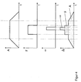
- FIG. 4 shows an idealized course of the opening cross-section A , a skyrocketing impact frequency F and a soaring rotational speed ⁇ during a filling process.
- the superimposition of these parameters ideally leads to the course of the mass flow ⁇ shown .
- both the opening cross section A , the impact frequency F and the rotational speed ⁇ exert an influence on the course of the mass flow ⁇ .
Landscapes
- Physics & Mathematics (AREA)
- General Physics & Mathematics (AREA)
- Basic Packing Technique (AREA)
- Control Of Non-Electrical Variables (AREA)
- Measuring Volume Flow (AREA)
- Weight Measurement For Supplying Or Discharging Of Specified Amounts Of Material (AREA)
Priority Applications (5)
| Application Number | Priority Date | Filing Date | Title |
|---|---|---|---|
| EP08162902A EP2159555B1 (de) | 2008-08-25 | 2008-08-25 | Verfahren und Vorrichtung zum Füllen von Zielbehältern |
| CN2009801379173A CN102165290B (zh) | 2008-08-25 | 2009-08-13 | 用于装填目标容器的方法和设备 |
| PCT/EP2009/060524 WO2010023111A1 (de) | 2008-08-25 | 2009-08-13 | Verfahren und vorrichtung zum füllen von zielbehältern |
| JP2011524315A JP5452599B2 (ja) | 2008-08-25 | 2009-08-13 | ターゲット容器を充填するための方法および装置 |
| US13/032,953 US8768632B2 (en) | 2008-08-25 | 2011-02-23 | Method and apparatus for the filling of target containers |
Applications Claiming Priority (1)
| Application Number | Priority Date | Filing Date | Title |
|---|---|---|---|
| EP08162902A EP2159555B1 (de) | 2008-08-25 | 2008-08-25 | Verfahren und Vorrichtung zum Füllen von Zielbehältern |
Publications (2)
| Publication Number | Publication Date |
|---|---|
| EP2159555A1 EP2159555A1 (de) | 2010-03-03 |
| EP2159555B1 true EP2159555B1 (de) | 2013-02-27 |
Family
ID=40263196
Family Applications (1)
| Application Number | Title | Priority Date | Filing Date |
|---|---|---|---|
| EP08162902A Not-in-force EP2159555B1 (de) | 2008-08-25 | 2008-08-25 | Verfahren und Vorrichtung zum Füllen von Zielbehältern |
Country Status (5)
| Country | Link |
|---|---|
| US (1) | US8768632B2 (https=) |
| EP (1) | EP2159555B1 (https=) |
| JP (1) | JP5452599B2 (https=) |
| CN (1) | CN102165290B (https=) |
| WO (1) | WO2010023111A1 (https=) |
Families Citing this family (7)
| Publication number | Priority date | Publication date | Assignee | Title |
|---|---|---|---|---|
| EP2372321B1 (de) | 2010-02-24 | 2012-11-07 | Mettler-Toledo AG | Verfahren und Vorrichtung zum Füllen von Zielbehältern |
| CA2874985A1 (en) | 2012-08-09 | 2014-02-13 | Basf Plant Science Company Gmbh | Fungal resistant plants expressing hcp5 |
| DE102013114720A1 (de) * | 2013-12-20 | 2015-06-25 | Bayer Technology Services Gmbh | Verfahren zum Betreiben einer modular aufgebauten Produktionsanlage |
| CN105403260A (zh) * | 2015-12-28 | 2016-03-16 | 中国科学院地理科学与资源研究所 | 流量测量装置和方法 |
| CN106932033A (zh) * | 2017-03-03 | 2017-07-07 | 山东大学 | 一种便携式隧道柱状涌水量测量装置及方法 |
| JP2020066475A (ja) * | 2018-10-22 | 2020-04-30 | 株式会社松井製作所 | 粉粒体材料の供給装置及び粉粒体材料の供給方法 |
| JP7105484B2 (ja) * | 2018-10-22 | 2022-07-25 | 株式会社松井製作所 | 粉粒体材料の供給装置 |
Family Cites Families (8)
| Publication number | Priority date | Publication date | Assignee | Title |
|---|---|---|---|---|
| US4893262A (en) | 1986-06-27 | 1990-01-09 | K-Tron International, Inc. | Weigh feeding system with self-tuning stochastic control |
| US4762252A (en) | 1987-05-08 | 1988-08-09 | Hyer Industries, Inc. | Adaptation to major or sporadic disturbance error in weigh feeding apparatus |
| DE3910028A1 (de) | 1988-03-29 | 1989-10-19 | Tron Int Inc | Verfahren und vorrichtung zur masseflussregelung eines gefoerderten materials |
| JPH0712628A (ja) * | 1993-06-24 | 1995-01-17 | Ajinomoto Co Inc | 粉体又は液体の計量制御方法 |
| FR2711610B1 (fr) * | 1993-10-29 | 1996-02-02 | Andre J J Graffin | Procédé de remplissage d'un récipient avec un poids net de référence. |
| GB9926335D0 (en) | 1999-11-05 | 2000-01-12 | Powderject Res Ltd | Apparatus and method for dispensing small quantities of particles |
| WO2007039611A1 (de) * | 2005-10-03 | 2007-04-12 | Mettler-Toledo Ag | Dosiereinrichtung für pulver- oder pastenförmige substanzen |
| EP2124025B1 (de) | 2008-05-22 | 2012-12-26 | Mettler-Toledo AG | Verfahren und Vorrichtung zum Füllen von Zielbehältern |
-
2008
- 2008-08-25 EP EP08162902A patent/EP2159555B1/de not_active Not-in-force
-
2009
- 2009-08-13 CN CN2009801379173A patent/CN102165290B/zh not_active Expired - Fee Related
- 2009-08-13 JP JP2011524315A patent/JP5452599B2/ja not_active Expired - Fee Related
- 2009-08-13 WO PCT/EP2009/060524 patent/WO2010023111A1/de not_active Ceased
-
2011
- 2011-02-23 US US13/032,953 patent/US8768632B2/en active Active
Also Published As
| Publication number | Publication date |
|---|---|
| WO2010023111A1 (de) | 2010-03-04 |
| EP2159555A1 (de) | 2010-03-03 |
| JP5452599B2 (ja) | 2014-03-26 |
| CN102165290B (zh) | 2013-10-16 |
| JP2012500984A (ja) | 2012-01-12 |
| US20110172934A1 (en) | 2011-07-14 |
| CN102165290A (zh) | 2011-08-24 |
| US8768632B2 (en) | 2014-07-01 |
Similar Documents
| Publication | Publication Date | Title |
|---|---|---|
| EP2372321B1 (de) | Verfahren und Vorrichtung zum Füllen von Zielbehältern | |
| EP2124025B1 (de) | Verfahren und Vorrichtung zum Füllen von Zielbehältern | |
| EP2159555B1 (de) | Verfahren und Vorrichtung zum Füllen von Zielbehältern | |
| EP0215080B1 (de) | Vorrichtung zum automatischen erfassen eines kontinuierlichen schüttgut-durchsatzes mittels einer durchlaufwaage | |
| EP1874450B1 (de) | Keramikpartikel | |
| EP2460761A1 (de) | Vorrichtung und Verfahren zum Befüllen von Behältnissen | |
| DE3942496A1 (de) | Verfahren zum dosierten auftragen eines fluessigen bindemittels, insbesondere von bitumen, auf eine oberflaeche | |
| DE4029620A1 (de) | Verfahren und vorrichtung zum genauen und sicheren dosieren von chargen beliebiger medien mit vorgabe eines soll-wertes einer messgroesse | |
| DE3416127A1 (de) | Vorrichtung und verfahren zur einstellung volumetrischer hohlraeume zum gravimetrischen dosieren von fluessigkeiten | |
| AT406251B (de) | Verfahren zum einstellen der dosiereinrichtung einer nach dem freifallprinzip arbeitenden füllmaschine für ventil- oder offene säcke | |
| DE60311667T2 (de) | Fluidbehandlungsvorrichtung mit ringförmigen strömungswegen, system und verfahren | |
| EP0806238B1 (de) | Vorrichtung zum Fördern dosierter Mengen mindestens zweier fliessfähiger Komponenten einer reaktiven Masse | |
| DE1598522B2 (de) | Verfahren zur bestimmung des fettgehaltes von fleisch und wurstmassen | |
| EP3003864B1 (de) | Packmaschine und verfahren | |
| EP0485772B1 (de) | Mahlwerk | |
| EP0033374B1 (de) | Verfahren zur automatischen Herstellung von Lösungen aus umweltbelastenden Stoffen | |
| DE3417372C2 (https=) | ||
| EP3651919A1 (de) | Giessvorrichtung zum giessen unter druck | |
| EP3698109B1 (de) | Verfahren und vorrichtung zur durchführung eines abfüllprozesses | |
| DE4331057C1 (de) | Optimierung der Rührerdrehzahl in einer mechanischen Dosiervorrichtung | |
| DE10063645A1 (de) | Präzisionszuführvorrichtung für dispergierte Pulver | |
| EP1157257A1 (de) | Verfahren und vorrichtung zur zeitgesteuerten dosierung von flüssigen produkten | |
| DE10251161B4 (de) | Verfahren und Vorrichtung zum Verfüllen von Behältnissen mit pulvrigem Füllgut | |
| AT389256B (de) | Verfahren zur steuerung des ausgusschiebers eines gefaesses fuer metallurgische abguesse | |
| DE19514270C1 (de) | Viskositätsmesser und Verfahren zur Viskositätsregelung |
Legal Events
| Date | Code | Title | Description |
|---|---|---|---|
| PUAI | Public reference made under article 153(3) epc to a published international application that has entered the european phase |
Free format text: ORIGINAL CODE: 0009012 |
|
| AK | Designated contracting states |
Kind code of ref document: A1 Designated state(s): AT BE BG CH CY CZ DE DK EE ES FI FR GB GR HR HU IE IS IT LI LT LU LV MC MT NL NO PL PT RO SE SI SK TR |
|
| AX | Request for extension of the european patent |
Extension state: AL BA MK RS |
|
| 17P | Request for examination filed |
Effective date: 20100811 |
|
| 17Q | First examination report despatched |
Effective date: 20100909 |
|
| AKX | Designation fees paid |
Designated state(s): AT BE BG CH CY CZ DE DK EE ES FI FR GB GR HR HU IE IS IT LI LT LU LV MC MT NL NO PL PT RO SE SI SK TR |
|
| GRAP | Despatch of communication of intention to grant a patent |
Free format text: ORIGINAL CODE: EPIDOSNIGR1 |
|
| GRAS | Grant fee paid |
Free format text: ORIGINAL CODE: EPIDOSNIGR3 |
|
| GRAA | (expected) grant |
Free format text: ORIGINAL CODE: 0009210 |
|
| AK | Designated contracting states |
Kind code of ref document: B1 Designated state(s): AT BE BG CH CY CZ DE DK EE ES FI FR GB GR HR HU IE IS IT LI LT LU LV MC MT NL NO PL PT RO SE SI SK TR |
|
| REG | Reference to a national code |
Ref country code: GB Ref legal event code: FG4D Free format text: NOT ENGLISH |
|
| REG | Reference to a national code |
Ref country code: CH Ref legal event code: EP |
|
| REG | Reference to a national code |
Ref country code: AT Ref legal event code: REF Ref document number: 598739 Country of ref document: AT Kind code of ref document: T Effective date: 20130315 |
|
| REG | Reference to a national code |
Ref country code: IE Ref legal event code: FG4D Free format text: LANGUAGE OF EP DOCUMENT: GERMAN |
|
| REG | Reference to a national code |
Ref country code: DE Ref legal event code: R096 Ref document number: 502008009330 Country of ref document: DE Effective date: 20130425 |
|
| REG | Reference to a national code |
Ref country code: LT Ref legal event code: MG4D |
|
| PG25 | Lapsed in a contracting state [announced via postgrant information from national office to epo] |
Ref country code: LT Free format text: LAPSE BECAUSE OF FAILURE TO SUBMIT A TRANSLATION OF THE DESCRIPTION OR TO PAY THE FEE WITHIN THE PRESCRIBED TIME-LIMIT Effective date: 20130227 Ref country code: BG Free format text: LAPSE BECAUSE OF FAILURE TO SUBMIT A TRANSLATION OF THE DESCRIPTION OR TO PAY THE FEE WITHIN THE PRESCRIBED TIME-LIMIT Effective date: 20130527 Ref country code: SE Free format text: LAPSE BECAUSE OF FAILURE TO SUBMIT A TRANSLATION OF THE DESCRIPTION OR TO PAY THE FEE WITHIN THE PRESCRIBED TIME-LIMIT Effective date: 20130227 Ref country code: NO Free format text: LAPSE BECAUSE OF FAILURE TO SUBMIT A TRANSLATION OF THE DESCRIPTION OR TO PAY THE FEE WITHIN THE PRESCRIBED TIME-LIMIT Effective date: 20130527 Ref country code: ES Free format text: LAPSE BECAUSE OF FAILURE TO SUBMIT A TRANSLATION OF THE DESCRIPTION OR TO PAY THE FEE WITHIN THE PRESCRIBED TIME-LIMIT Effective date: 20130607 Ref country code: IS Free format text: LAPSE BECAUSE OF FAILURE TO SUBMIT A TRANSLATION OF THE DESCRIPTION OR TO PAY THE FEE WITHIN THE PRESCRIBED TIME-LIMIT Effective date: 20130627 |
|
| REG | Reference to a national code |
Ref country code: NL Ref legal event code: VDEP Effective date: 20130227 |
|
| PG25 | Lapsed in a contracting state [announced via postgrant information from national office to epo] |
Ref country code: SI Free format text: LAPSE BECAUSE OF FAILURE TO SUBMIT A TRANSLATION OF THE DESCRIPTION OR TO PAY THE FEE WITHIN THE PRESCRIBED TIME-LIMIT Effective date: 20130227 Ref country code: PL Free format text: LAPSE BECAUSE OF FAILURE TO SUBMIT A TRANSLATION OF THE DESCRIPTION OR TO PAY THE FEE WITHIN THE PRESCRIBED TIME-LIMIT Effective date: 20130227 Ref country code: PT Free format text: LAPSE BECAUSE OF FAILURE TO SUBMIT A TRANSLATION OF THE DESCRIPTION OR TO PAY THE FEE WITHIN THE PRESCRIBED TIME-LIMIT Effective date: 20130627 Ref country code: FI Free format text: LAPSE BECAUSE OF FAILURE TO SUBMIT A TRANSLATION OF THE DESCRIPTION OR TO PAY THE FEE WITHIN THE PRESCRIBED TIME-LIMIT Effective date: 20130227 Ref country code: GR Free format text: LAPSE BECAUSE OF FAILURE TO SUBMIT A TRANSLATION OF THE DESCRIPTION OR TO PAY THE FEE WITHIN THE PRESCRIBED TIME-LIMIT Effective date: 20130528 Ref country code: LV Free format text: LAPSE BECAUSE OF FAILURE TO SUBMIT A TRANSLATION OF THE DESCRIPTION OR TO PAY THE FEE WITHIN THE PRESCRIBED TIME-LIMIT Effective date: 20130227 |
|
| PG25 | Lapsed in a contracting state [announced via postgrant information from national office to epo] |
Ref country code: HR Free format text: LAPSE BECAUSE OF FAILURE TO SUBMIT A TRANSLATION OF THE DESCRIPTION OR TO PAY THE FEE WITHIN THE PRESCRIBED TIME-LIMIT Effective date: 20130227 |
|
| PG25 | Lapsed in a contracting state [announced via postgrant information from national office to epo] |
Ref country code: RO Free format text: LAPSE BECAUSE OF FAILURE TO SUBMIT A TRANSLATION OF THE DESCRIPTION OR TO PAY THE FEE WITHIN THE PRESCRIBED TIME-LIMIT Effective date: 20130227 Ref country code: EE Free format text: LAPSE BECAUSE OF FAILURE TO SUBMIT A TRANSLATION OF THE DESCRIPTION OR TO PAY THE FEE WITHIN THE PRESCRIBED TIME-LIMIT Effective date: 20130227 Ref country code: DK Free format text: LAPSE BECAUSE OF FAILURE TO SUBMIT A TRANSLATION OF THE DESCRIPTION OR TO PAY THE FEE WITHIN THE PRESCRIBED TIME-LIMIT Effective date: 20130227 Ref country code: NL Free format text: LAPSE BECAUSE OF FAILURE TO SUBMIT A TRANSLATION OF THE DESCRIPTION OR TO PAY THE FEE WITHIN THE PRESCRIBED TIME-LIMIT Effective date: 20130227 Ref country code: SK Free format text: LAPSE BECAUSE OF FAILURE TO SUBMIT A TRANSLATION OF THE DESCRIPTION OR TO PAY THE FEE WITHIN THE PRESCRIBED TIME-LIMIT Effective date: 20130227 Ref country code: CZ Free format text: LAPSE BECAUSE OF FAILURE TO SUBMIT A TRANSLATION OF THE DESCRIPTION OR TO PAY THE FEE WITHIN THE PRESCRIBED TIME-LIMIT Effective date: 20130227 |
|
| PG25 | Lapsed in a contracting state [announced via postgrant information from national office to epo] |
Ref country code: CY Free format text: LAPSE BECAUSE OF FAILURE TO SUBMIT A TRANSLATION OF THE DESCRIPTION OR TO PAY THE FEE WITHIN THE PRESCRIBED TIME-LIMIT Effective date: 20130227 |
|
| PG25 | Lapsed in a contracting state [announced via postgrant information from national office to epo] |
Ref country code: IT Free format text: LAPSE BECAUSE OF FAILURE TO SUBMIT A TRANSLATION OF THE DESCRIPTION OR TO PAY THE FEE WITHIN THE PRESCRIBED TIME-LIMIT Effective date: 20130227 |
|
| PLBE | No opposition filed within time limit |
Free format text: ORIGINAL CODE: 0009261 |
|
| STAA | Information on the status of an ep patent application or granted ep patent |
Free format text: STATUS: NO OPPOSITION FILED WITHIN TIME LIMIT |
|
| 26N | No opposition filed |
Effective date: 20131128 |
|
| BERE | Be: lapsed |
Owner name: METTLER-TOLEDO A.G. Effective date: 20130831 |
|
| REG | Reference to a national code |
Ref country code: DE Ref legal event code: R097 Ref document number: 502008009330 Country of ref document: DE Effective date: 20131128 |
|
| REG | Reference to a national code |
Ref country code: CH Ref legal event code: PL |
|
| GBPC | Gb: european patent ceased through non-payment of renewal fee |
Effective date: 20130825 |
|
| PG25 | Lapsed in a contracting state [announced via postgrant information from national office to epo] |
Ref country code: MC Free format text: LAPSE BECAUSE OF FAILURE TO SUBMIT A TRANSLATION OF THE DESCRIPTION OR TO PAY THE FEE WITHIN THE PRESCRIBED TIME-LIMIT Effective date: 20130227 Ref country code: LI Free format text: LAPSE BECAUSE OF NON-PAYMENT OF DUE FEES Effective date: 20130831 Ref country code: CH Free format text: LAPSE BECAUSE OF NON-PAYMENT OF DUE FEES Effective date: 20130831 |
|
| REG | Reference to a national code |
Ref country code: IE Ref legal event code: MM4A |
|
| REG | Reference to a national code |
Ref country code: FR Ref legal event code: ST Effective date: 20140430 |
|
| PG25 | Lapsed in a contracting state [announced via postgrant information from national office to epo] |
Ref country code: BE Free format text: LAPSE BECAUSE OF NON-PAYMENT OF DUE FEES Effective date: 20130831 |
|
| PG25 | Lapsed in a contracting state [announced via postgrant information from national office to epo] |
Ref country code: IE Free format text: LAPSE BECAUSE OF NON-PAYMENT OF DUE FEES Effective date: 20130825 Ref country code: GB Free format text: LAPSE BECAUSE OF NON-PAYMENT OF DUE FEES Effective date: 20130825 |
|
| PG25 | Lapsed in a contracting state [announced via postgrant information from national office to epo] |
Ref country code: FR Free format text: LAPSE BECAUSE OF NON-PAYMENT OF DUE FEES Effective date: 20130902 |
|
| REG | Reference to a national code |
Ref country code: AT Ref legal event code: MM01 Ref document number: 598739 Country of ref document: AT Kind code of ref document: T Effective date: 20130825 |
|
| PG25 | Lapsed in a contracting state [announced via postgrant information from national office to epo] |
Ref country code: AT Free format text: LAPSE BECAUSE OF NON-PAYMENT OF DUE FEES Effective date: 20130825 |
|
| PG25 | Lapsed in a contracting state [announced via postgrant information from national office to epo] |
Ref country code: MT Free format text: LAPSE BECAUSE OF FAILURE TO SUBMIT A TRANSLATION OF THE DESCRIPTION OR TO PAY THE FEE WITHIN THE PRESCRIBED TIME-LIMIT Effective date: 20130227 Ref country code: TR Free format text: LAPSE BECAUSE OF FAILURE TO SUBMIT A TRANSLATION OF THE DESCRIPTION OR TO PAY THE FEE WITHIN THE PRESCRIBED TIME-LIMIT Effective date: 20130227 |
|
| PG25 | Lapsed in a contracting state [announced via postgrant information from national office to epo] |
Ref country code: LU Free format text: LAPSE BECAUSE OF NON-PAYMENT OF DUE FEES Effective date: 20130825 Ref country code: HU Free format text: LAPSE BECAUSE OF FAILURE TO SUBMIT A TRANSLATION OF THE DESCRIPTION OR TO PAY THE FEE WITHIN THE PRESCRIBED TIME-LIMIT; INVALID AB INITIO Effective date: 20080825 |
|
| REG | Reference to a national code |
Ref country code: DE Ref legal event code: R081 Ref document number: 502008009330 Country of ref document: DE Owner name: METTLER-TOLEDO GMBH, CH Free format text: FORMER OWNER: METTLER-TOLEDO AG, GREIFENSEE, CH |
|
| PGFP | Annual fee paid to national office [announced via postgrant information from national office to epo] |
Ref country code: DE Payment date: 20190715 Year of fee payment: 12 |
|
| REG | Reference to a national code |
Ref country code: DE Ref legal event code: R119 Ref document number: 502008009330 Country of ref document: DE |
|
| PG25 | Lapsed in a contracting state [announced via postgrant information from national office to epo] |
Ref country code: DE Free format text: LAPSE BECAUSE OF NON-PAYMENT OF DUE FEES Effective date: 20210302 |