EP2159104A1 - Trittplattenausfahrvorrichtung - Google Patents
Trittplattenausfahrvorrichtung Download PDFInfo
- Publication number
- EP2159104A1 EP2159104A1 EP08165614A EP08165614A EP2159104A1 EP 2159104 A1 EP2159104 A1 EP 2159104A1 EP 08165614 A EP08165614 A EP 08165614A EP 08165614 A EP08165614 A EP 08165614A EP 2159104 A1 EP2159104 A1 EP 2159104A1
- Authority
- EP
- European Patent Office
- Prior art keywords
- tread
- plate
- tread plate
- extension device
- guide means
- Prior art date
- Legal status (The legal status is an assumption and is not a legal conclusion. Google has not performed a legal analysis and makes no representation as to the accuracy of the status listed.)
- Granted
Links
Images


Classifications
-
- B—PERFORMING OPERATIONS; TRANSPORTING
- B60—VEHICLES IN GENERAL
- B60R—VEHICLES, VEHICLE FITTINGS, OR VEHICLE PARTS, NOT OTHERWISE PROVIDED FOR
- B60R3/00—Arrangements of steps or ladders facilitating access to or on the vehicle, e.g. running-boards
- B60R3/02—Retractable steps or ladders, e.g. movable under shock
-
- B—PERFORMING OPERATIONS; TRANSPORTING
- B61—RAILWAYS
- B61D—BODY DETAILS OR KINDS OF RAILWAY VEHICLES
- B61D23/00—Construction of steps for railway vehicles
- B61D23/02—Folding steps for railway vehicles, e.g. hand or mechanically actuated
- B61D23/025—Folding steps for railway vehicles, e.g. hand or mechanically actuated electrically or fluid actuated
Definitions
- the present invention relates to a Trittplattenausfahrvorraum for an extendable footboard of a door entry of a passenger transport vehicle, wherein the tread plate from a rest position into a position of use and back is movable.
- Such approach and access aids are used in vehicles for passenger transport, such as buses or rail vehicles of public transport. They are known in many forms and facilitate entry and exit in that in the area of stops on the vehicles slidably and usually also pivotally mounted foot plates are extended. Tread plates are used for bridging gaps (for example, on platforms) or for height compensation. Finally, they facilitate or allow wheelchair users access to the vehicles. After completion of the training and entry phase and possibly after closing the vehicle doors the tread plate is returned to its rest position.
- the tread plates are usually made of a durable and rigid but lightweight material and are usually provided with a slip-resistant pad.
- step plates are also manually ein./a publishede and folding treadplates known.
- a motor is provided in externally operated boarding aids, which moves the tread plate from its rest position into the position of use and back again.
- Such motor-operated tread plates are for example in the publications DE 20 2007 000 912 U1 .
- DE 20 2005 012 584 U1 and DE 20 2006 017 716 U1 describe.
- the walk-through footboard is laterally attached to guide means over which they can be linearly extended and retracted. In the extended end position is usually a lowering of the footboard necessary.
- a cross-beam is provided at the rear end of the tread plate, which is also in communication with the guide means.
- the tread plate and the cross-beam are in turn with the help of a hinge, a hinge, a plastic tape or the like with each other connected.
- This "articulated" connection between the crossbeam and the tread plate allows the lowering of the tread plate on the ground, such as a platform, curb or the road surface.
- a disadvantage of known Trittplattenausfahrvorraumen of this kind is that the necessary for the lowering of the tread plate intermediate means for a space to use, on the other hand dirty or can be damaged during use. Often there are the guide means and also the motor for driving the treadboard within a frame, which is used as a separate and complete unit in a corresponding space on the vehicle. Since the installation space for such tread plates is usually limited, the installation space required by the intermediate means also means that the walk-through tread plate itself can only have smaller dimensions.
- the drive of the tread plate may be different, e.g. by lateral spindles, which in addition to the drive also take over the function of the guide, or by a central drive, which requires additional (for example lateral) guide means.
- lateral spindles which in addition to the drive also take over the function of the guide
- central drive which requires additional (for example lateral) guide means.
- Other drive options are also realized, but this is not discussed in the context of this patent application.
- the object of the present invention is to provide a Trittplattenausfahrvorraum, which is compact and space-saving design. It should allow a motorized extension of the tread plate and also a lowering or pivoting of the tread plate in the extended position. Furthermore, the o.g. Disadvantages of the prior art can be avoided.
- the Trittplattenausfahrvoroplasty invention thus consists of a tread plate, two hinged thereto guide elements, which are connected to the in-side / outward direction of the tread plate extending guide means.
- the guide means themselves can in turn be arranged in a kind of frame which, in addition to two side parts, also has a transverse rear part.
- the entire tread extension device is attached to the vehicle via the frame.
- the tread plate is attached via laterally arranged guide elements directly pivotally mounted on the laterally extending guide means.
- the adverse intermediate means which are thus arranged between the tread plate and the usual crossbeam, can be completely eliminated. Accordingly, the entire Trittplattenausfahrvorplatz in input / extension direction is shorter, fewer components are needed and also the assembly and disassembly is easier to perform. In particular, can be dispensed with the otherwise necessary cross-beam, which means a further significant weight reduction.
- the drive of the tread plate is preferably via an electric motor, which may also be attached to the frame.
- the guide means are designed as spindle nuts, each extending through an opening in one of the guide elements. The openings have an internal thread for this purpose, so that a rotation of the spindle nut leads to a process of the guide elements and thus the tread plate.
- an additional drive shaft may be provided which drives the tread plate; the guide means then transmit no force.
- the guide elements are arranged opposite each other and have a base body with the through opening for the guide means and a pin portion, which extends in the installed state of Trittplattenausfahrvoriques in each case a receiving opening of the treadboard inside.
- the pin portion has a circular cross-section so that the tread plate is pivotable about the pin portions. In the fully extended position, the footboard is no longer resting on the frame and may be due to lower the pivoting about the pin portions down or can be pivoted upwards.
- the tread plate is movable to some extent. This has the great advantage that a displacement of the guide means, which can also occur in the course of use, is compensated, the tread plate does not tilt during retraction and extension. Also, the component tolerances may be higher for the initial assembly, which saves costs and effort.
- the receiving openings of the tread plate formed as blind holes which are so deep that they can accommodate the pin sections over its entire length.
- the spigot portions may have some play in their longitudinal direction in the receiving apertures, further increasing the degrees of freedom and movability of the kick plate extending device.
- the pin portions along the longitudinal axis of the pin portions extending axis Y-Y are displaced, whereby a deviation of the parallelism of the guide means can be compensated. So do not run the guide means exactly parallel to each other, but they open, for example, in the extension direction, this can be compensated by moving the pin sections in the receiving openings.
- sleeves can also be provided which can be inserted into the receiving openings and into which the pin sections extend.
- Such sleeves are made for example of plastic and facilitate the movement of the preferably made of metal guide element in the receiving opening.
- the Trittplattenausfahrvoroplasty invention not only saves space, also the articulated storage always protected from external influences.
- the guide elements are less exposed to dirt and moisture, whereby the entire tread extension device has a long life.
- the tread plate may preferably be divided into a main plate and an adjoining rear edge profile.
- the guide elements or the journal sections of the guide elements then extend laterally into the trailing edge profile, which has the corresponding receiving openings.
- This embodiment is particularly advantageous in terms of the production of tread plates, since the main plate can be cut or made of a durable material quickly and easily, while only the trailing edge profiles must be made with appropriate accuracy.
- the receiving openings can also be designed as a continuous bore, which extends through the entire tread plate or the entire trailing edge profile.
- the tread plate may protrude pin portions extending into receiving openings, which are introduced into the guide elements.
- the receiving openings are preferably arranged at the rear end of the tread plate, so that only a small area protrudes when lowering the tread plate. Alternatively, however, an arrangement of the receiving openings in other places is possible depending on the requirement profile.
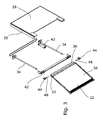
- FIG. 1 shows a Trittplattenausfahrvorraum invention 20 with an extended footboard 22.
- the Trittplattenausfahrvorraum 20 works in principle like a drawer, the tread plate 22 is moved into a housing 24 on or out of this.
- the housing 24 has an opening through which the tread plate 22 can be retracted and extended.
- the tread plate 22 is pivotally mounted so that it can be at least lowered in the extended state, but advantageously can also be pivoted upwards.
- FIG. 2 shows the tread extension device 20 from above with the cover plate removed 26.
- the housing 24 has a frame 28 consisting of two side parts 30 and a rear part 32.
- this frame guide means 34 are fixed, which extend laterally of the tread plate 22 in the direction of the extension / retraction direction (arrow).
- the guide means 34 may be designed as spindle nuts.
- the frame 28 may be formed as a composite part.
- the tread plate 22 is formed by a main plate 36 and an adjoining rear edge profile 38.
- the trailing edge profile 38 is screwed or riveted to the main plate 36, for example, but it can also be glued.
- the tread plate 22 may also be formed in one piece, a separate trailing edge profile 38 is then not necessary.
- An electric motor 40 is fixed to one end of a guide means 34 and drives the guide means 34. It can be driven both guide means 34, but it may also be sufficient to drive only one guide means 34, while the other guide means 34 only the guide and not the Power transmission is used. It is also conceivable embodiment, in which not the guide means 34 are driven themselves, but an additional central drive for the movement of the tread plate 22 is provided.
- the housing 24 may further comprise a front support cross member 42, on which the tread plate 22 rests in the retracted state and also during the driving movement.
- FIGS. 3 and 4 show guide elements 44, which cause the pivotal mounting of the tread plate 22.
- the guide elements 44 have a base body 46, which merges into a pin portion 48. Through the base body 46 extends an opening 50 through which a guide means 34 extends in the installed state. If the guide means 34 designed as a spindle nut, the opening 50 has a corresponding internal thread.
- the pin portion 46 extends in the installed state of the Trittplattenausfahrvorides 20 laterally into a receiving opening 52 of the tread plate 22 and the trailing edge profile 38 into it.
- the tread plate 22 is pivotable about an axis Y-Y extending along the longitudinal axis of the pin portion 48 and axes X-X extending along the guide means 34.
- FIG. 4 shows a sleeve 54 which can be inserted into a receiving opening 52, in order in turn to be able to receive the journal section 48.
- FIG. 5 illustrates that there are also other conceivable variants of the guide element 44 and an associated guide means 34.
- the guide element 44 has an elongate, rod-shaped body 56 which is guided in a longitudinal groove 58 of the guide means 34.
- Trittplattenausfahrvoroplasty 20 is very fast and easy to mount by their swiveling in almost all directions storage, the demands on the manufacture of the components in terms of their dimensions can be significantly lower than in known Trittplattenausfahrvortechnischen 20th be.
- the available space is better utilized and the joints are better protected against environmental influences.
Abstract
Description
- Die vorliegende Erfindung betrifft eine Trittplattenausfahrvorrichtung für eine ausfahrbare Trittplatte eines Türeinstiegs eines Personenbeförderungsfahrzeuges, wobei die Trittplatte aus einer Ruhestellung in eine Gebrauchsstellung und zurück verfahrbar ist.
- Derartige Zustiegs- und Zufahrtshilfen werden bei Fahrzeugen zur Personenbeförderung, beispielsweise bei Bussen oder Schienenfahrzeugen des öffentlichen Nahverkehrs eingesetzt. Sie sind in vielfältiger Form bekannt und erleichtern den Ein- und Ausstieg dadurch, dass im Bereich von Haltestellen an den Fahrzeugen verschiebbar und meist auch verschwenkbar gelagerte Trittplatten ausgefahren werden. Trittplatten werden dabei zur Überbrückung von Spalten (beispielsweise bei Bahnsteigen) oder auch zum Höhenausgleich eingesetzt. Schließlich erleichtern oder ermöglichen sie Rollstuhlfahrern den Zugang in die Fahrzeuge. Nach Beendigung der Aus- und Einstiegsphase und eventuell nach dem Schließen der Fahrzeugtüren wird die Trittplatte wieder in ihre Ruhestellung zurückgebracht.
- Die Trittplatten bestehen in der Regel aus einem widerstandsfähigen und starren, aber leichten Material und sind in der Regel mit einer rutschhemmenden Auflage versehen.
- Neben motorisch ausfahrbaren Trittplatten sind ebenfalls manuell ein./ausziehbare sowie klappbare Trittplatten bekannt. Im Bereich der Trittplatte ist bei fremdbetriebenen Zustiegshilfen ein Motor vorgesehen, der die Trittplatte aus ihrer Ruhestellung in die Gebrauchsstellung heraus- und wieder zurückfährt. Derartige motorisch betriebene Trittplatten sind beispielsweise in den Druckschriften
DE 20 2007 000 912 U1 ,DE 20 2005 012 584 U1 undDE 20 2006 017 716 U1 beschreiben. Wie auch diesen Druckschriften zu entnehmen ist, ist die begehbare Trittplatte seitlich an Führungsmitteln befestigt, über die sie linear ein- und ausgefahren werden kann. In der ausgefahrenen Endstellung ist meist ein Absenken der Trittplatte notwendig. Zu diesem Zweck ist am hinteren Ende der Trittplatte eine Quertraverse vorgesehen, die ebenfalls mit den Führungsmitteln in Verbindung steht. Die Trittplatte und die Quertraverse sind wiederum mit Hilfe eines Gelenkbandes, einem Scharnier, einem Kunststoffband oder ähnlichem miteinander verbunden. Diese "gelenkige" Verbindung zwischen der Quertraverse und der Trittplatte erlaubt das Absenken der Trittplatte auf den Untergrund, beispielsweise einen Bahnsteig, Bordstein oder auch die Fahrbahnoberfläche. - Nachteilig bei bekannten Trittplattenausfahrvorrichtungen dieser Art ist, dass die für das Absenken der Trittplatte notwendigen Zwischenmittel zum einen Bauraum benötigen, zum anderen aber bei Gebrauch verschmutzen oder beschädigt werden können. Oftmals befinden sich die Führungsmittel und auch der Motor zum Antrieb der Trittplatte innerhalb eines Rahmens, der als eigenständige und komplette Einheit in einen entsprechenden Bauraum am Fahrzeug eingesetzt wird. Da der Einbauraum für derartige Trittplatten in der Regel begrenzt ist, führt der durch die Zwischenmittel benötigte Bauraum auch dazu, dass die begehbare Trittplatte selbst nur geringere Abmessungen aufweisen kann.
- Der Antrieb der Trittplatte kann verschieden ausgeführt sein, z.B. durch seitliche Spindeln, welche neben dem Antrieb ebenfalls die Funktion der Führung übernehmen, oder auch durch einen zentralen Antrieb, welcher zusätzliche (z.B. seitliche) Führungsmittel erfordert. Weitere Antriebsmöglichkeiten sind ebenfalls realisiert, auf diese wird jedoch im Rahmen dieser Patentanmeldung nicht eingegangen.
- Die Aufgabe der vorliegenden Erfindung besteht darin, eine Trittplattenausfahrvorrichtung zu schaffen, die kompakt und Platz sparend aufgebaut ist. Sie soll ein motorisches Ausfahren der Trittplatte und auch ein Absenken oder Hochschwenken der Trittplatte in der Ausfahrposition ermöglichen. Weiterhin sollen die o.g. Nachteile des Standes der Technik vermieden werden.
- Erfindungsgemäß wird die Aufgabe durch eine Trittplattenausfahrvorrichtung gelöst, die dadurch gekennzeichnet ist, dass
- Führungsmittel vorgesehen sind, die jeweils seitlich der Trittplatte in Ein-/Ausfahrrichtung verlaufen und,
- die Trittplatte über Führungselemente mit den Führungsmitteln derart verbunden ist, dass die Trittplatte sowohl um Längsachsen, die in Längsrichtung der Führungsmittel verlaufen, als auch entlang einer Längsachse, die durch die Führungselemente und quer zu den Längsachsen verläuft, schwenkbar ist.
- Die erfindungsgemäße Trittplattenausfahrvorrichtung besteht also aus einer Trittplatte, zwei daran gelenkig angeordneten Führungselementen, die mit in Ein-/Ausfahrrichtung seitlich der Trittplatte verlaufenden Führungsmitteln verbunden sind. Die Führungsmittel selbst können wiederum in einer Art Rahmen angeordnet sein, der neben zwei Seitenteilen auch ein quer verlaufendes Rückteil aufweist. Über den Rahmen wird die gesamte Trittplattenausfahrvorrichtung am Fahrzeug befestigt.
- Erfindungsgemäß ist also die Trittplatte über seitlich angeordnete Führungselemente unmittelbar schwenkbar an den seitlich verlaufenden Führungsmitteln befestigt. Auf die nachteiligen Zwischenmittel, die somit zwischen der Trittplatte und der sonst üblichen Quertraverse angeordnet sind, kann vollständig verzichtet werden. Entsprechend baut die gesamte Trittplattenausfahrvorrichtung in Ein-/Ausfahrrichtung kürzer, es werden weniger Bauteile benötigt und auch die Montage und Demontage ist einfacher durchzuführen. Insbesondere kann auch auf die sonst notwendige Quertraverse verzichtet werden, was eine weitere erhebliche Gewichtsreduzierung bedeutet.
- Der Antrieb der Trittplatte erfolgt vorzugsweise über einen Elektromotor, der ebenfalls am Rahmen befestigt sein kann. In einer besonders bevorzugten Ausführungsvariante sind die Führungsmittel als Spindelmuttern ausgeführt, die sich jeweils durch eine Öffnung in einem der Führungselemente erstrecken. Die Öffnungen weisen zu diesem Zweck ein Innengewinde auf, so dass eine Drehung der Spindelmutter zu einem Verfahren der Führungselemente und damit der Trittplatte führt. Alternativ kann auch eine zusätzliche Antriebswelle vorgesehen sein, die die Trittplatte antreibt; die Führungsmittel übertragen dann keine Kraft.
- Die Führungselemente sind einander gegenüberliegend angeordnet und weisen einen Grundkörper mit der durchgehenden Öffnung für die Führungsmittel und einen Zapfenabschnitt, auf der sich im eingebauten Zustand der Trittplattenausfahrvorrichtung in jeweils eine Aufnahmeöffnung der Trittplatte hinein erstreckt. Der Zapfenabschnitt weist einen kreisförmigen Querschnitt auf, so dass die Trittplatte um die Zapfenabschnitte schwenkbar ist. In der vollständig ausgefahrenen Position liegt die Trittplatte nicht mehr auf dem Rahmen auf und kann sich aufgrund der Schwenkbarkeit um die Zapfenabschnitte nach unten absenken oder kann nach oben geschwenkt werden.
- Dadurch, dass die Führungselemente auch um die Führungsmittel schwenkbar sind, ist die Trittplatte in gewissem Rahmen bewegbar. Dies hat den großen Vorteil, dass ein Versatz der Führungsmittel, der auch im Laufe der Nutzung entstehen kann, ausgeglichen wird, die Trittplatte verkantet sich beim Ein- und Ausfahren nicht. Auch können die Bauteiltoleranzen für die Erstmontage höher ausfallen, was Kosten und Aufwand einspart.
- Schließlich hat es sich als besonders vorteilhaft erwiesen, wenn die Aufnahmeöffnungen der Trittplatte als Sacklöcher ausgebildet, die derart tief sind, dass sie die Zapfenabschnitte über ihre gesamte Länge aufnehmen können. Die Zapfenabschnitte können in den Aufnahmeöffnungen ein gewisses Spiel in ihrer Längsrichtung haben, was die Freiheitsgrade und die Bewegbarkeit der Trittplattenausfahrvorrichtung weiter erhöht. Weiterhin sind die Zapfenabschnitte entlang der in Längsachse der Zapfenabschnitte verlaufenden Achse Y-Y verschiebbar, wodurch eine Abweichung der Parallelität der Führungsmittel ausgeglichen werden kann. Laufen die Führungsmittel also nicht exakt parallel zueinander, sondern öffnen sie sich beispielsweise in Ausfahrrichtung, kann dies durch ein Verschieben der Zapfenabschnitte in den Aufnahmeöffnungen ausgeglichen werden.
- Erfindungsgemäß können auch Hülsen vorgesehen sein, die in die Aufnahmeöffnungen einführbar sind und in die sich die Zapfenabschnitte erstrecken. Derartige Hülsen sind beispielsweise aus Kunststoff gefertigt und erleichtern die Bewegung des vorzugsweise aus Metall gefertigten Führungselementes in der Aufnahmeöffnung.
- Die erfindungsgemäße Trittplattenausfahrvorrichtung spart nicht nur Raum ein, auch bleibt die gelenkige Lagerung stets vor äußeren Einflüssen geschützt. Im Gegensatz zu einem Gelenkband oder Scharnier sind die Führungselemente Schmutz und Feuchtigkeit weniger ausgesetzt, wodurch die gesamte Trittplattenausfahrvorrichtung eine lange Lebensdauer aufweist.
- Die Trittplatte kann vorzugsweise in eine Hauptplatte und eine sich daran anschließendes Hinterkantenprofil aufgeteilt sein. Die Führungselemente bzw. die Zapfenabschnitte der Führungselemente erstrecken sich dann seitlich in das Hinterkantenprofil, das die entsprechenden Aufnahmeöffnungen aufweist. Diese Ausführung ist insbesondere hinsichtlich der Herstellung der Trittplatten vorteilhaft, da die Hauptplatte aus einem widerstandsfähigem Material schnell und einfach geschnitten oder gefertigt werden kann, während lediglich die Hinterkantenprofile mit entsprechender Genauigkeit gefertigt werden müssen.
- Anstelle von Sacklöchern können die Aufnahmeöffnungen auch als eine durchgängige Bohrung ausgeführt sein, die sich durch die gesamte Trittplatte bzw. das gesamte Hinterkantenprofil hindurch erstreckt.
- Denkbar ist natürlich auch eine kinematische Umkehr der Führungselemente, von der Trittplatte können Zapfenabschnitte vorstehen, die sich in Aufnahmeöffnungen hinein erstrecken, die in die Führungselemente eingebracht sind.
- Die Aufnahmeöffnungen sind vorzugsweise am hinteren Ende der Trittplatte angeordnet, so dass beim Absenken der Trittplatte nur ein geringer Bereich übersteht. Alternativ ist aber je nach Anforderungsprofil auch eine Anordnung der Aufnahmeöffnungen an anderen Stellen möglich.
- Anhand der nachfolgenden Figuren wird die Erfindung näher erläutert. Diese sind nur beispielhaft zu verstehen und sollen den Umfang der Erfindung nicht beschränken. Es zeigen:
- Figur 1:
- Eine Trittplattenausfahrvorrichtung in perspektivischer Darstellung, mit ausgefahrener Trittplatte,
- Figur 2:
- Die Trittplattenausfahrvorrichtung aus
Figur 1 mit abgenommener Deckplatte von oben, - Figur 3:
- die Trittplattenausfahrvorrichtung aus
Figur 1 in einer Explosionsansicht, - Figur 4:
- eine weitere Explosionsansicht der erfindungsgemäßen Trittplattenausfahrvorrichtung.
- Figur 5:
- eine zweite Ausführung eines Führungselements mit einem zugehörigen Führungsmittel.
-
Figur 1 zeigt eine erfindungsgemäße Trittplattenausfahrvorrichtung 20 mit einer ausgefahrenen Trittplatte 22. Die Trittplattenausfahrvorrichtung 20 funktioniert prinzipiell nach Art einer Schublade, die Trittplatte 22 wird in ein Gehäuse 24 ein- oder aus diesem herausgefahren. Das Gehäuse 24 weist hierzu eine Öffnung auf, durch die die Trittplatte 22 ein- und ausfahrbar ist. - Die Trittplatte 22 ist schwenkbar gelagert, so dass sie im ausgefahrenen Zustand zumindest abgesenkt, vorteilhafterweise aber auch nach oben geschwenkt werden kann.
-
Figur 2 zeigt die Trittplattenausfahrvorrichtung 20 von oben mit abgenommener Deckplatte 26. Erkennbar ist, dass das Gehäuse 24 einen Rahmen 28, bestehend aus zwei Seitenteilen 30 und einem Rückteil 32 aufweist. An diesem Rahmen sind Führungsmittel 34 befestigt, die sich seitlich der Trittplatte 22 in Richtung der Ein-/Ausfahrrichtung (Pfeil) erstrecken. Die Führungsmittel 34 können als Spindelmuttern ausgeführt sein. Der Rahmen 28 kann als Verbundteil ausgebildet sein. - In der gezeigten Ausführungsvariante ist die Trittplatte 22 durch eine Hauptplatte 36 und ein sich daran anschließendes Hinterkantenprofil 38 gebildet. Das Hinterkantenprofil 38 ist mit der Hauptplatte 36 beispielsweise verschraubt oder vernietet, es kann aber auch geklebt sein. Alternativ zur zweiteiligen Ausführung kann die Trittplatte 22 auch einteilig ausgebildet sein, ein separates Hinterkantenprofil 38 ist dann nicht notwendig.
- Ein Elektromotor 40 ist an einem Ende eines Führungsmittels 34 befestigt und treibt die Führungsmittel 34 an. Es können beide Führungsmittel 34 angetrieben sein, es kann aber auch ausreichen, lediglich ein Führungsmittel 34 anzutreiben, während das andere Führungsmittel 34 lediglich der Führung und nicht der Kraftübertragung dient. Denkbar ist auch eine Ausführungsvariante, bei der nicht die Führungsmittel 34 selbst angetrieben werden, sondern ein zusätzlicher zentraler Antrieb für die Bewegung der Trittplatte 22 vorgesehen ist.
- Das Gehäuse 24 kann weiterhin eine vordere Auflagetraverse 42 aufweisen, auf der die Trittplatte 22 im eingefahrenen Zustand und auch während der Fahrbewegung aufliegt.
- Insbesondere die
Figuren 3 und4 zeigen Führungselemente 44, die die schwenkbare Lagerung der Trittplatte 22 bewirken. Die Führungselemente 44 weisen einen Grundkörper 46 auf, der in einen Zapfenabschnitt 48 übergeht. Durch den Grundkörper 46 verläuft eine Öffnung 50, durch die sich im eingebauten Zustand jeweils ein Führungsmittel 34 erstreckt. Ist das Führungsmittel 34 als Spindelmutter ausgeführt, weist die Öffnung 50 ein entsprechendes Innengewinde auf. - Der Zapfenabschnitt 46 erstreckt sich im eingebauten Zustand der Trittplattenausfahrvorrichtung 20 seitlich in eine Aufnahmeöffnung 52 der Trittplatte 22 bzw. des Hinterkantenprofils 38 hinein. Somit ist die Trittplatte 22 um eine sich entlang der Längsachse des Zapfenabschnitts 48 erstreckende Achse Y-Y und sich entlang der Führungsmittel 34 erstreckende Achsen X-X schwenkbar.
- Weiterhin zeigt
Figur 4 , dass eine Hülse 54 verwendbar ist, die in eine Aufnahmeöffnung 52 hineingesteckt werden kann, um selbst wiederum den Zapfenabschnitt 48 aufnehmen zu können. -
Figur 5 verdeutlicht, dass auch weitere denkbare Varianten des Führungselements 44 und einem zugehörigen Führungsmittel 34 gibt. Das Führungselement 44 weist einen länglichen, stabförmigen Körper 56 auf, der in einer Längsnut 58 des Führungsmittels 34 geführt ist. - Die erfindungsgemäße Trittplattenausfahrvorrichtung 20 ist durch ihre in nahezu alle Richtungen schwenkbare Lagerung sehr schnell und einfach zu montieren, die Ansprüche an die Fertigung der Bauteile hinsichtlich ihrer Abmessungen können deutlich niedriger als bei bekannten Trittplattenausfahrvorrichtungen 20 sein. Der vorhandene Bauraum wird besser ausgenutzt und die Gelenke sind gegenüber Umwelteinflüssen besser geschützt.
Claims (8)
- Trittplattenausfahrvorrichtung (20) für eine ausfahrbare Trittplatte (22) eines Türeinstiegs eines Personenbeförderungsfahrzeuges, wobei die Trittplatte (22) aus einer Ruhestellung in eine Gebrauchsstellung und zurück verfahrbar ist,
dadurch gekennzeichnet, dass- Führungsmittel (34) vorgesehen sind, die jeweils seitlich der Trittplatte (22) in Ein-/Ausfahrrichtung verlaufen und,- die Trittplatte (22) über Führungselemente (44) mit den Führungsmitteln (34) derart verbunden ist, dass die Trittplatte (22) sowohl um Längsachsen (X-X), die in Längsrichtung der Führungsmittel (34) verlaufen, als auch entlang einer Längsachse (Y-Y), die durch die Führungselemente (44) und quer zu den Längsachsen (X-X) verläuft, schwenkbar ist. - Trittplattenausfahrvorrichtung (20) nach Anspruch 1,
dadurch gekennzeichnet, dass
die Führungselemente (44) jeweils aufweisen:- einen Grundkörper (46) mit einer durchgehenden Öffnung (50), durch die sich jeweils ein Führungsmittel (34) erstreckt,- einen sich an den Grundkörper (46) anschließenden Zapfenabschnitt (48), der sich in eine Aufnahmeöffnung (52) der Trittplatte (20) hineinerstreckt. - Trittplattenausfahrvorrichtung (20) nach Anspruch 2,
dadurch gekennzeichnet, dass
die Zapfenabschnitte (48) in den Aufnahmeöffnungen (52) in ihrer Längsrichtung verschiebbar sind. - Trittplattenausfahrvorrichtung (20) nach einem der Ansprüche 1 bis 3,
dadurch gekennzeichnet, dass
zumindest ein Führungsmittel (44) als Spindelmutter ausgeführt ist, die die Trittplatte (22) antreibt. - Trittplattenausfahrvorrichtung (20) nach einem der Ansprüche 1 bis 3,
dadurch gekennzeichnet, dass
weiterhin eine Antriebswelle vorgesehen ist, die die Trittplatte(22) antreibt. - Trittplattenausfahrvorrichtung (20) nach einem der Ansprüche 2 bis 5,
dadurch gekennzeichnet, dass
die Trittplatte (22) durch eine Hauptplatte (36) und ein sich daran anschließendes Hinterkantenprofil (38) gebildet ist, wobei das Hinterkantenprofil (38) die Aufnahmeöffnungen (52) aufweist. - Trittplattenausfahrvorrichtung (20) nach einem der Ansprüche 1 bis 6,
dadurch gekennzeichnet, dass
das Gehäuse (24) weiterhin eine vordere Auflagetraverse (42) aufweist, auf der die Trittplatte (22) im eingefahrenen Zustand und auch während der Fahrbewegung aufliegt. - Trittplattenausfahrvorrichtung (20) nach einem der Ansprüche 2 bis 7,
dadurch gekennzeichnet, dass
dass in den Aufnahmeöffnungen (52) Hülse (54) angeordnet sind, in die jeweils ein Zapfenabschnitt (48) einführbar ist.
Priority Applications (1)
| Application Number | Priority Date | Filing Date | Title |
|---|---|---|---|
| PL08165614T PL2159104T3 (pl) | 2007-10-05 | 2008-10-01 | Urządzenie do wysuwania płyty wejściowej |
Applications Claiming Priority (1)
| Application Number | Priority Date | Filing Date | Title |
|---|---|---|---|
| DE202007013960U DE202007013960U1 (de) | 2007-10-05 | 2007-10-05 | Trittplattenausfahrvorrichtung |
Publications (2)
| Publication Number | Publication Date |
|---|---|
| EP2159104A1 true EP2159104A1 (de) | 2010-03-03 |
| EP2159104B1 EP2159104B1 (de) | 2012-03-07 |
Family
ID=40365607
Family Applications (1)
| Application Number | Title | Priority Date | Filing Date |
|---|---|---|---|
| EP08165614A Not-in-force EP2159104B1 (de) | 2007-10-05 | 2008-10-01 | Trittplattenausfahrvorrichtung |
Country Status (5)
| Country | Link |
|---|---|
| EP (1) | EP2159104B1 (de) |
| AT (1) | ATE548220T1 (de) |
| DE (1) | DE202007013960U1 (de) |
| ES (1) | ES2381393T3 (de) |
| PL (1) | PL2159104T3 (de) |
Citations (5)
| Publication number | Priority date | Publication date | Assignee | Title |
|---|---|---|---|---|
| WO1998006370A1 (en) * | 1996-08-15 | 1998-02-19 | Tieman Industries Pty. Ltd. | A retractable ramp assembly |
| US6167816B1 (en) * | 1998-06-05 | 2001-01-02 | Westinghouse Air Brake Company | Single screw bridgeplate |
| DE202005012584U1 (de) | 2005-07-29 | 2005-12-01 | Hübner Transportation GmbH | Rampe für einen Türeinstieg eines Personenbeförderungsfahrzeugs |
| DE202006017716U1 (de) | 2005-11-17 | 2007-03-01 | Kircher, Werner | Zustiegs- und/oder Zufahrtshilfe mit einer beweglichen Trittplatte zur Erfassung von vertikalen und/oder horizontalen, auf die Trittplatte einwirkenden Störkräften an Fahrzeugen zur Personenbeförderung |
| DE202007000912U1 (de) | 2007-01-18 | 2007-04-05 | Kircher, Werner | Zustiegs- und/oder Zufahrtshilfe für Fahrzeuge mit Personenbeförderung |
Family Cites Families (1)
| Publication number | Priority date | Publication date | Assignee | Title |
|---|---|---|---|---|
| DE202007000913U1 (de) * | 2006-11-17 | 2007-04-05 | Kircher, Werner | Zustiegs- und/oder Zufahrtshilfe für Fahrzeuge mit Personenbeförderung |
-
2007
- 2007-10-05 DE DE202007013960U patent/DE202007013960U1/de not_active Expired - Lifetime
-
2008
- 2008-10-01 ES ES08165614T patent/ES2381393T3/es active Active
- 2008-10-01 EP EP08165614A patent/EP2159104B1/de not_active Not-in-force
- 2008-10-01 PL PL08165614T patent/PL2159104T3/pl unknown
- 2008-10-01 AT AT08165614T patent/ATE548220T1/de active
Patent Citations (5)
| Publication number | Priority date | Publication date | Assignee | Title |
|---|---|---|---|---|
| WO1998006370A1 (en) * | 1996-08-15 | 1998-02-19 | Tieman Industries Pty. Ltd. | A retractable ramp assembly |
| US6167816B1 (en) * | 1998-06-05 | 2001-01-02 | Westinghouse Air Brake Company | Single screw bridgeplate |
| DE202005012584U1 (de) | 2005-07-29 | 2005-12-01 | Hübner Transportation GmbH | Rampe für einen Türeinstieg eines Personenbeförderungsfahrzeugs |
| DE202006017716U1 (de) | 2005-11-17 | 2007-03-01 | Kircher, Werner | Zustiegs- und/oder Zufahrtshilfe mit einer beweglichen Trittplatte zur Erfassung von vertikalen und/oder horizontalen, auf die Trittplatte einwirkenden Störkräften an Fahrzeugen zur Personenbeförderung |
| DE202007000912U1 (de) | 2007-01-18 | 2007-04-05 | Kircher, Werner | Zustiegs- und/oder Zufahrtshilfe für Fahrzeuge mit Personenbeförderung |
Also Published As
| Publication number | Publication date |
|---|---|
| ATE548220T1 (de) | 2012-03-15 |
| EP2159104B1 (de) | 2012-03-07 |
| PL2159104T3 (pl) | 2012-08-31 |
| DE202007013960U1 (de) | 2009-02-19 |
| ES2381393T3 (es) | 2012-05-25 |
Similar Documents
| Publication | Publication Date | Title |
|---|---|---|
| EP3237254B1 (de) | Schiebetritt mit hub- und rampenfunktion | |
| EP1946968B1 (de) | Zustiegs- und/oder Zufahrtshilfe für Fahrzeuge mit Personenbeförderung | |
| EP2065260B1 (de) | Türkantenschutzeinrichtung | |
| EP1946735B1 (de) | Zustiegs- und/oder Zufahrtshilfe für Fahrzeuge mit Personenbeförderung | |
| AT500017B1 (de) | Schwenkschiebetür für fahrzeuge | |
| EP2627537B1 (de) | Rampe mit seitlicher barriere | |
| EP1925499B1 (de) | Zustiegs- und/oder Zufahrtshilfe für Fahrzeuge mit Personenbeförderung | |
| EP2614974A2 (de) | Rollosystem für ein Kraftfahrzeug | |
| EP3549900A1 (de) | Hebebühne für kraftfahrzeuge | |
| WO1997034793A1 (de) | Seitenwand für den aufbau eines fahrzeuges | |
| EP2044916B1 (de) | Trittplattenvorrichtung | |
| EP3663158A1 (de) | Trittsystem für ein fahrzeug | |
| EP3181106A1 (de) | Teleskopmechanismus | |
| EP2365171A2 (de) | Lagerung einer Klappe an einem Aufbau eines Kraftwagens sowie Karosserie für einen solchen Kraftwagen | |
| WO2011045052A1 (de) | Verkleidungsanordnung für einen schwenkarm einer kraftwagentür | |
| EP1800640A1 (de) | Ausstellbare Trittstufe eines Fahrzeugs | |
| DE19952597A1 (de) | Treppe | |
| EP2159104B1 (de) | Trittplattenausfahrvorrichtung | |
| EP4077843B1 (de) | Führungsanordnung zur führung wenigstens eines bewegbaren möbelteils | |
| EP2243679B1 (de) | Rollensystem mit Abstützfunktion für ein Schiebetritt | |
| DE10131367B4 (de) | Rampe für einen Türeinstieg | |
| EP1128016B1 (de) | Antrieb für einen beweglichen Gebäudeabschluss, Zugmittelgetriebe und Führungsschiene zur Verwendung darin und Verfahren zur Montage derselben | |
| DE202006001230U1 (de) | Fahrzeugtür | |
| DE3028887A1 (de) | Unbewegliche nachruestvorrichtung an fahrzeugaufbauten | |
| DE102009006847B4 (de) | Verkaufswagen |
Legal Events
| Date | Code | Title | Description |
|---|---|---|---|
| PUAI | Public reference made under article 153(3) epc to a published international application that has entered the european phase |
Free format text: ORIGINAL CODE: 0009012 |
|
| AK | Designated contracting states |
Kind code of ref document: A1 Designated state(s): AT BE BG CH CY CZ DE DK EE ES FI FR GB GR HR HU IE IS IT LI LT LU LV MC MT NL NO PL PT RO SE SI SK TR |
|
| AX | Request for extension of the european patent |
Extension state: AL BA MK RS |
|
| 17P | Request for examination filed |
Effective date: 20100903 |
|
| AKX | Designation fees paid |
Designated state(s): AT BE BG CH CY CZ DE DK EE ES FI FR GB GR HR HU IE IS IT LI LT LU LV MC MT NL NO PL PT RO SE SI SK TR |
|
| 17Q | First examination report despatched |
Effective date: 20101202 |
|
| GRAP | Despatch of communication of intention to grant a patent |
Free format text: ORIGINAL CODE: EPIDOSNIGR1 |
|
| GRAS | Grant fee paid |
Free format text: ORIGINAL CODE: EPIDOSNIGR3 |
|
| GRAA | (expected) grant |
Free format text: ORIGINAL CODE: 0009210 |
|
| AK | Designated contracting states |
Kind code of ref document: B1 Designated state(s): AT BE BG CH CY CZ DE DK EE ES FI FR GB GR HR HU IE IS IT LI LT LU LV MC MT NL NO PL PT RO SE SI SK TR |
|
| REG | Reference to a national code |
Ref country code: GB Ref legal event code: FG4D Free format text: NOT ENGLISH |
|
| REG | Reference to a national code |
Ref country code: AT Ref legal event code: REF Ref document number: 548220 Country of ref document: AT Kind code of ref document: T Effective date: 20120315 Ref country code: CH Ref legal event code: EP |
|
| REG | Reference to a national code |
Ref country code: IE Ref legal event code: FG4D Free format text: LANGUAGE OF EP DOCUMENT: GERMAN |
|
| REG | Reference to a national code |
Ref country code: DE Ref legal event code: R096 Ref document number: 502008006615 Country of ref document: DE Effective date: 20120510 |
|
| REG | Reference to a national code |
Ref country code: ES Ref legal event code: FG2A Ref document number: 2381393 Country of ref document: ES Kind code of ref document: T3 Effective date: 20120525 Ref country code: DE Ref legal event code: R082 Ref document number: 502008006615 Country of ref document: DE Representative=s name: BAUER-VORBERG-KAYSER, DE Ref country code: DE Ref legal event code: R082 Ref document number: 502008006615 Country of ref document: DE Representative=s name: PATENTANWAELTE BAUER VORBERG KAYSER PARTNERSCH, DE |
|
| REG | Reference to a national code |
Ref country code: NL Ref legal event code: T3 |
|
| PG25 | Lapsed in a contracting state [announced via postgrant information from national office to epo] |
Ref country code: LT Free format text: LAPSE BECAUSE OF FAILURE TO SUBMIT A TRANSLATION OF THE DESCRIPTION OR TO PAY THE FEE WITHIN THE PRESCRIBED TIME-LIMIT Effective date: 20120307 Ref country code: NO Free format text: LAPSE BECAUSE OF FAILURE TO SUBMIT A TRANSLATION OF THE DESCRIPTION OR TO PAY THE FEE WITHIN THE PRESCRIBED TIME-LIMIT Effective date: 20120607 Ref country code: HR Free format text: LAPSE BECAUSE OF FAILURE TO SUBMIT A TRANSLATION OF THE DESCRIPTION OR TO PAY THE FEE WITHIN THE PRESCRIBED TIME-LIMIT Effective date: 20120307 |
|
| LTIE | Lt: invalidation of european patent or patent extension |
Effective date: 20120307 |
|
| PG25 | Lapsed in a contracting state [announced via postgrant information from national office to epo] |
Ref country code: GR Free format text: LAPSE BECAUSE OF FAILURE TO SUBMIT A TRANSLATION OF THE DESCRIPTION OR TO PAY THE FEE WITHIN THE PRESCRIBED TIME-LIMIT Effective date: 20120608 Ref country code: FI Free format text: LAPSE BECAUSE OF FAILURE TO SUBMIT A TRANSLATION OF THE DESCRIPTION OR TO PAY THE FEE WITHIN THE PRESCRIBED TIME-LIMIT Effective date: 20120307 Ref country code: LV Free format text: LAPSE BECAUSE OF FAILURE TO SUBMIT A TRANSLATION OF THE DESCRIPTION OR TO PAY THE FEE WITHIN THE PRESCRIBED TIME-LIMIT Effective date: 20120307 |
|
| REG | Reference to a national code |
Ref country code: PL Ref legal event code: T3 |
|
| PG25 | Lapsed in a contracting state [announced via postgrant information from national office to epo] |
Ref country code: CY Free format text: LAPSE BECAUSE OF FAILURE TO SUBMIT A TRANSLATION OF THE DESCRIPTION OR TO PAY THE FEE WITHIN THE PRESCRIBED TIME-LIMIT Effective date: 20120307 |
|
| PG25 | Lapsed in a contracting state [announced via postgrant information from national office to epo] |
Ref country code: RO Free format text: LAPSE BECAUSE OF FAILURE TO SUBMIT A TRANSLATION OF THE DESCRIPTION OR TO PAY THE FEE WITHIN THE PRESCRIBED TIME-LIMIT Effective date: 20120307 Ref country code: SE Free format text: LAPSE BECAUSE OF FAILURE TO SUBMIT A TRANSLATION OF THE DESCRIPTION OR TO PAY THE FEE WITHIN THE PRESCRIBED TIME-LIMIT Effective date: 20120307 Ref country code: SI Free format text: LAPSE BECAUSE OF FAILURE TO SUBMIT A TRANSLATION OF THE DESCRIPTION OR TO PAY THE FEE WITHIN THE PRESCRIBED TIME-LIMIT Effective date: 20120307 Ref country code: IS Free format text: LAPSE BECAUSE OF FAILURE TO SUBMIT A TRANSLATION OF THE DESCRIPTION OR TO PAY THE FEE WITHIN THE PRESCRIBED TIME-LIMIT Effective date: 20120707 Ref country code: EE Free format text: LAPSE BECAUSE OF FAILURE TO SUBMIT A TRANSLATION OF THE DESCRIPTION OR TO PAY THE FEE WITHIN THE PRESCRIBED TIME-LIMIT Effective date: 20120307 |
|
| PG25 | Lapsed in a contracting state [announced via postgrant information from national office to epo] |
Ref country code: PT Free format text: LAPSE BECAUSE OF FAILURE TO SUBMIT A TRANSLATION OF THE DESCRIPTION OR TO PAY THE FEE WITHIN THE PRESCRIBED TIME-LIMIT Effective date: 20120709 Ref country code: SK Free format text: LAPSE BECAUSE OF FAILURE TO SUBMIT A TRANSLATION OF THE DESCRIPTION OR TO PAY THE FEE WITHIN THE PRESCRIBED TIME-LIMIT Effective date: 20120307 |
|
| PLBE | No opposition filed within time limit |
Free format text: ORIGINAL CODE: 0009261 |
|
| STAA | Information on the status of an ep patent application or granted ep patent |
Free format text: STATUS: NO OPPOSITION FILED WITHIN TIME LIMIT |
|
| PG25 | Lapsed in a contracting state [announced via postgrant information from national office to epo] |
Ref country code: DK Free format text: LAPSE BECAUSE OF FAILURE TO SUBMIT A TRANSLATION OF THE DESCRIPTION OR TO PAY THE FEE WITHIN THE PRESCRIBED TIME-LIMIT Effective date: 20120307 |
|
| 26N | No opposition filed |
Effective date: 20121210 |
|
| REG | Reference to a national code |
Ref country code: DE Ref legal event code: R097 Ref document number: 502008006615 Country of ref document: DE Effective date: 20121210 |
|
| PG25 | Lapsed in a contracting state [announced via postgrant information from national office to epo] |
Ref country code: MC Free format text: LAPSE BECAUSE OF NON-PAYMENT OF DUE FEES Effective date: 20121031 |
|
| REG | Reference to a national code |
Ref country code: CH Ref legal event code: PL |
|
| REG | Reference to a national code |
Ref country code: IE Ref legal event code: MM4A |
|
| PG25 | Lapsed in a contracting state [announced via postgrant information from national office to epo] |
Ref country code: BG Free format text: LAPSE BECAUSE OF FAILURE TO SUBMIT A TRANSLATION OF THE DESCRIPTION OR TO PAY THE FEE WITHIN THE PRESCRIBED TIME-LIMIT Effective date: 20120607 Ref country code: LI Free format text: LAPSE BECAUSE OF NON-PAYMENT OF DUE FEES Effective date: 20121031 Ref country code: IE Free format text: LAPSE BECAUSE OF NON-PAYMENT OF DUE FEES Effective date: 20121001 Ref country code: CH Free format text: LAPSE BECAUSE OF NON-PAYMENT OF DUE FEES Effective date: 20121031 |
|
| PG25 | Lapsed in a contracting state [announced via postgrant information from national office to epo] |
Ref country code: MT Free format text: LAPSE BECAUSE OF FAILURE TO SUBMIT A TRANSLATION OF THE DESCRIPTION OR TO PAY THE FEE WITHIN THE PRESCRIBED TIME-LIMIT Effective date: 20120307 |
|
| PG25 | Lapsed in a contracting state [announced via postgrant information from national office to epo] |
Ref country code: LU Free format text: LAPSE BECAUSE OF NON-PAYMENT OF DUE FEES Effective date: 20121001 |
|
| PG25 | Lapsed in a contracting state [announced via postgrant information from national office to epo] |
Ref country code: HU Free format text: LAPSE BECAUSE OF FAILURE TO SUBMIT A TRANSLATION OF THE DESCRIPTION OR TO PAY THE FEE WITHIN THE PRESCRIBED TIME-LIMIT Effective date: 20081001 |
|
| REG | Reference to a national code |
Ref country code: AT Ref legal event code: MM01 Ref document number: 548220 Country of ref document: AT Kind code of ref document: T Effective date: 20131001 |
|
| PG25 | Lapsed in a contracting state [announced via postgrant information from national office to epo] |
Ref country code: AT Free format text: LAPSE BECAUSE OF NON-PAYMENT OF DUE FEES Effective date: 20131001 |
|
| REG | Reference to a national code |
Ref country code: FR Ref legal event code: PLFP Year of fee payment: 8 |
|
| REG | Reference to a national code |
Ref country code: FR Ref legal event code: PLFP Year of fee payment: 9 |
|
| REG | Reference to a national code |
Ref country code: FR Ref legal event code: PLFP Year of fee payment: 10 |
|
| REG | Reference to a national code |
Ref country code: FR Ref legal event code: PLFP Year of fee payment: 11 |
|
| PGFP | Annual fee paid to national office [announced via postgrant information from national office to epo] |
Ref country code: NL Payment date: 20181022 Year of fee payment: 11 |
|
| PGFP | Annual fee paid to national office [announced via postgrant information from national office to epo] |
Ref country code: PL Payment date: 20181019 Year of fee payment: 11 Ref country code: CZ Payment date: 20181019 Year of fee payment: 11 Ref country code: DE Payment date: 20181024 Year of fee payment: 11 |
|
| PGFP | Annual fee paid to national office [announced via postgrant information from national office to epo] |
Ref country code: GB Payment date: 20181025 Year of fee payment: 11 Ref country code: IT Payment date: 20181022 Year of fee payment: 11 Ref country code: ES Payment date: 20181122 Year of fee payment: 11 Ref country code: FR Payment date: 20181023 Year of fee payment: 11 Ref country code: BE Payment date: 20181022 Year of fee payment: 11 Ref country code: TR Payment date: 20181019 Year of fee payment: 11 |
|
| REG | Reference to a national code |
Ref country code: DE Ref legal event code: R119 Ref document number: 502008006615 Country of ref document: DE |
|
| PG25 | Lapsed in a contracting state [announced via postgrant information from national office to epo] |
Ref country code: CZ Free format text: LAPSE BECAUSE OF NON-PAYMENT OF DUE FEES Effective date: 20191001 |
|
| REG | Reference to a national code |
Ref country code: NL Ref legal event code: MM Effective date: 20191101 |
|
| PG25 | Lapsed in a contracting state [announced via postgrant information from national office to epo] |
Ref country code: DE Free format text: LAPSE BECAUSE OF NON-PAYMENT OF DUE FEES Effective date: 20200501 |
|
| REG | Reference to a national code |
Ref country code: BE Ref legal event code: MM Effective date: 20191031 |
|
| PG25 | Lapsed in a contracting state [announced via postgrant information from national office to epo] |
Ref country code: NL Free format text: LAPSE BECAUSE OF NON-PAYMENT OF DUE FEES Effective date: 20191101 Ref country code: BE Free format text: LAPSE BECAUSE OF NON-PAYMENT OF DUE FEES Effective date: 20191031 |
|
| GBPC | Gb: european patent ceased through non-payment of renewal fee |
Effective date: 20191001 |
|
| PG25 | Lapsed in a contracting state [announced via postgrant information from national office to epo] |
Ref country code: FR Free format text: LAPSE BECAUSE OF NON-PAYMENT OF DUE FEES Effective date: 20191031 Ref country code: GB Free format text: LAPSE BECAUSE OF NON-PAYMENT OF DUE FEES Effective date: 20191001 Ref country code: IT Free format text: LAPSE BECAUSE OF NON-PAYMENT OF DUE FEES Effective date: 20191001 |
|
| REG | Reference to a national code |
Ref country code: ES Ref legal event code: FD2A Effective date: 20210301 |
|
| PG25 | Lapsed in a contracting state [announced via postgrant information from national office to epo] |
Ref country code: ES Free format text: LAPSE BECAUSE OF NON-PAYMENT OF DUE FEES Effective date: 20191002 |
|
| PG25 | Lapsed in a contracting state [announced via postgrant information from national office to epo] |
Ref country code: PL Free format text: LAPSE BECAUSE OF NON-PAYMENT OF DUE FEES Effective date: 20191001 |
|
| PG25 | Lapsed in a contracting state [announced via postgrant information from national office to epo] |
Ref country code: TR Free format text: LAPSE BECAUSE OF NON-PAYMENT OF DUE FEES Effective date: 20191001 |