EP2158643B1 - Steckkontaktierung - Google Patents
Steckkontaktierung Download PDFInfo
- Publication number
- EP2158643B1 EP2158643B1 EP08735081A EP08735081A EP2158643B1 EP 2158643 B1 EP2158643 B1 EP 2158643B1 EP 08735081 A EP08735081 A EP 08735081A EP 08735081 A EP08735081 A EP 08735081A EP 2158643 B1 EP2158643 B1 EP 2158643B1
- Authority
- EP
- European Patent Office
- Prior art keywords
- contact
- plug
- contact part
- housing
- parts
- Prior art date
- Legal status (The legal status is an assumption and is not a legal conclusion. Google has not performed a legal analysis and makes no representation as to the accuracy of the status listed.)
- Active
Links
Images

Classifications
-
- H—ELECTRICITY
- H01—ELECTRIC ELEMENTS
- H01R—ELECTRICALLY-CONDUCTIVE CONNECTIONS; STRUCTURAL ASSOCIATIONS OF A PLURALITY OF MUTUALLY-INSULATED ELECTRICAL CONNECTING ELEMENTS; COUPLING DEVICES; CURRENT COLLECTORS
- H01R13/00—Details of coupling devices of the kinds covered by groups H01R12/70 or H01R24/00 - H01R33/00
- H01R13/46—Bases; Cases
- H01R13/52—Dustproof, splashproof, drip-proof, waterproof, or flameproof cases
- H01R13/5219—Sealing means between coupling parts, e.g. interfacial seal
Definitions
- the invention relates to an electrical plug-in contact with at least one first contact part and at least one second contact part, wherein a contact part can be engaged by the other and in a mated position, the two contact parts are aligned.
- the object of the invention is to provide an electrical contact, which allows contacting both in the axial direction and transversely or obliquely, in particular at right angles to this and in both mated positions, the contacts are securely held. It is another object of the invention to provide an electrical plug-in contact, which ensure sufficient tightness in the axial mated position and in a right-angle mated position.
- the second contact part is attached in particular transversely or obliquely to the mating direction of the first position on the first contact part.
- the first contact part is formed by an elongated tongue-shaped flat part, the two side surfaces of which can be engaged by the second contact part.
- a secure seal especially against contact and against moisture is achieved when the contact parts are each surrounded by a housing and sealingly abuts in two infected positions each housing with a sealing surface on the sealing surface of the other housing. It is particularly advantageous if the sealing surfaces of both housings are arranged obliquely, in particular at an angle of 45 degrees to the insertion direction and / or to the longitudinal direction of the contact part. The tightness is further increased if at least one of the two sealing surfaces carries a seal.
- At least one of the contact parts has at least one introduction surface, in particular an insertion bevel, on which the forked or clamp-shaped second contact part slides.
- the inner contact part is covered by a plastic, in particular overmolded on at least one end face on which the outer cross-sectional contact part comes to the first contact.
- the plastic can form at least one introduction surface in particular an insertion bevel, wherein the insertion bevel is formed by a chamfer (s) is / are.
- first contact parts next to each other and / or one above the other form a first contact group, which is surrounded by a housing with oblique sealing surface, and that two or more second contact parts next to each other and / or lying over a second contact group also form surrounded by a housing with an oblique sealing surface.
- the contact parts of both contact groups can each be next to one another in a row.
- the plug contact can be used on a pump, in particular between terminal box / electronics box and the electric motor.
- the contacting according to the invention may be attached to the first or second contact part (s) on any electrical device, wherein the second / first contact part (s) are attached to a second device which is to be connected to a first contacting, wherein the second device may be a plug or a terminal box / electrical or electronic box.
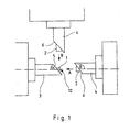
- the first contact part 1 is formed by a tongue-shaped metal profile, which is overlapped by a second contact part 2, wherein the second contact part 2 has fork-shaped surfaces which engage over the first contact part, when the two contact parts 1,2 in the direction of arrow A. in the axial direction, ie in the direction of the longitudinal axis of the contact parts 1,2 to the first mated position are fastened together.
- the two first contact parts 1, 2 are each surrounded by a housing 3, 4, wherein the housing 3, 4 can rest tight against the contact parts 1, 2, so that in this case the contacts 1, 2 are encapsulated by the plastic of the housing can.
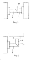
- the construction also allows contacting in a direction perpendicular to the longitudinal direction or axis of the contact part 1, such as FIG. 3 shows.
- the second contact part 2 does not overlap the first contact part 1 in the longitudinal or axial direction, but at right angles thereto, so that the second contact part 2 engages over the first contact part 1 from the side.
- the first contact part on the front side and laterally on insertion bevels in particular in the form of chamfers.
- the front end face 12 of the first contact part 1 can be rounded or bevelled two or more times.
- the first contact part 1 may also be encapsulated on its front side and / or on a narrow side of plastic 7, wherein these plastic supports form an end-side lead-in bevel 8 and a lateral lead-in bevel 9 or a rounding or two or more bevels.
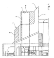
- FIGS. 5 and 6 It is shown that two or more contact parts, four contact parts in the embodiment, are arranged side by side to form a first contact group 10.
- first contact groups 10 In the embodiment according to FIGS. 5 and 6
- second contact parts are arranged to form a second contact group.
- the contact parts 1,2 may be arranged not only next to each other in a row, but also in a group, in particular in parallel rows.
- the plug connection according to the invention is advantageously used / used in pumps between the terminal box or electronics box and the electric motor.
Landscapes
- Connector Housings Or Holding Contact Members (AREA)
- Coupling Device And Connection With Printed Circuit (AREA)
Description
- Die Erfindung betrifft eine elektrische Steckkontaktierung mit mindestens einem ersten Kontaktteil und mindestens einem zweiten Kontaktteil, wobei ein Kontaktteil vom anderen übergreifbar ist und in einer zusammengesteckten Position die beiden Kontaktteile miteinander fluchten.
- Es ist bekannt elektrische Kontakte miteinander zu verbinden, indem die Kontakte in Achsrichtung aneinander befestigt werden, wobei ein Kontakt den anderen übergreift. Eine solche Steckverbindung ist aus der
FR-A-2 376 533 - Ferner ist es bekannt, Kontakte rechtwinklig aneinander zu befestigen. Beide Bauarten erfordern unterschiedliche Konstruktionen.
- Aufgabe der Erfindung ist es, eine elektrische Kontaktierung zu schaffen, die ein Kontaktieren sowohl in Axialrichtung als auch quer oder schräg insbesondere rechtwinklig dazu ermöglicht und dazu in beiden zusammengesteckten Positionen die Kontakte sicher gehalten sind. Ferner ist es Aufgabe der Erfindung eine elektrische Steckkontaktierung zu schaffen, die in axialer zusammengesteckter Position sowie in rechtwinkliger zusammengesteckter Position eine ausreichende Dichtheit gewährleisten.
- Diese Aufgaben werden dadurch gelöst, dass in einer zweiten zusammengesteckten Position das zweite Kontaktteil quer oder schräg zur Steckrichtung der ersten Position am ersten Kontaktteil ansteckbar insbesondere angesteckt ist.
- Vorzugsweise wird hierbei vorgeschlagen, dass das erste Kontaktteil von einem länglichen zungenförmigen Flachteil gebildet ist, dessen zwei Seitenflächen von dem zweiten Kontaktteil übergreifbar sind.
- Eine sichere Abdichtung insbesondere gegen Berührung und gegen Feuchtigkeit wird erreicht, wenn die Kontaktteile jeweils von einem Gehäuse umgeben sind und in beiden angesteckten Stellungen jedes Gehäuse mit einer Dichtfläche an der Dichtfläche des anderen Gehäuses dichtend anliegt. Hierbei ist es besonders vorteilhaft, wenn die Dichtflächen beider Gehäuse schräg insbesondere in einem Winkel von 45 Grad zur Steckrichtung und/oder zur Längsrichtung des Kontaktteils angeordnet sind. Die Dichtigkeit wird noch erhöht, wenn mindestens eine der beiden Dichtflächen eine Dichtung trägt.
- Um das Befestigen in Steckrichtung zu erleichtern wird vorgeschlagen, dass mindestens eines der Kontaktteile mindestens eine Einführungsfläche insbesondere eine Einführungsschräge aufweist, auf der das gabel- oder klammerförmige zweite Kontaktteil aufgleitet.
- Es ist von Vorteil, wenn das innere Kontaktteil an mindestens einer Stirnseite, an der das äußere übergreifende Kontaktteil zur ersten Berührung gelangt, von einem Kunststoff bedeckt insbesondere umspritzt ist. Hierbei kann der Kunststoff mindestens eine Einführungsfläche insbesondere eine Einführungsschräge bilden, wobei die Einführungsschräge von einer Fase(n) gebildet ist/sind.
- Vorteilhaft ist es, wenn zwei oder mehr erste Kontaktteile nebeneinander und/oder übereinander liegend eine erste Kontaktgruppe bilden, die von einem Gehäuse mit Schräger Dichtfläche umgeben ist, und dass zwei oder mehr zweite Kontaktteile nebeneinander und/oder übereinander liegend eine zweite Kontaktgruppe bilden die ebenfalls von einem Gehäuse mit schräger Dichtfläche umgeben ist. Hierbei können die Kontaktteile beider Kontaktgruppen jeweils in einer Reihe nebeneinander liegen. Besonders vorteilhaft ist die Steckkontaktierung an einer Pumpe verwendbar, insbesondere zwischen Klemmenkasten/Elektronikkasten und dem Elektromotor.
- Ausführungsbeispiele der Erfindung sind in den Zeichnungen dargestellt und werden im Folgenden näher beschrieben.
- Es zeigen:
- Fig. 1
- Kontaktteile mit Gehäusen in beiden Steckrichtungen vor dem Aneinanderstecken
- Fig. 2
- in axialer Richtung aneinander gesteckte Teile
- Fig. 3
- in rechtwinkliger Richtung aneinander gesteckte Teile
- Fig. 4
- einen axialen Schnitt durch das erste Kontaktteil mit Gehäuse befestigt an einem Motor
- Fig. 5
- eine Stirnansicht eines Motors mit vier in einer Gruppe angeordneten Kontaktteilen
- Fig. 6
- eine Oberansicht des Motors mit der Gruppe von Kontaktteilen
- Die erfindungsgemäße Kontaktierung kann mit dem/den ersten oder zweiten Kontaktteil(en) an irgendeiner elektrischen Vorrichtung befestigt sein, wobei das/die zweiten/ersten Kontaktteil(en) an einer zweiten Vorrichtung befestigt sind, die an einer ersten kontaktierend angesteckt werden soll, wobei die zweite Vorrichtung ein Stecker oder ein Klemmenkasten/Elektrik- oder Elektronikkasten sein kann.
- Im Ausführungsbeispiel wird das erste Kontaktteil 1 von einem zungenförmigen Metallprofil gebildet, das von einem zweiten Kontaktteil 2 übergreifbar ist, wobei das zweite Kontaktteil 2 gabelförmig angeordnete Flächen besitzt, die das erste Kontaktteil übergreifen, wenn die beiden Kontaktteile 1,2 in Richtung des Pfeils A in Axialrichtung, d.h. in Richtung der Längsachse der Kontaktteile 1,2 zur ersten zusammengesteckten Position aneinander befestigt werden. Hierbei sind die beiden ersten Kontaktteile 1,2 jeweils von einem Gehäuse 3,4 umgeben, wobei die Gehäuse 3,4 dicht an den Kontaktteilen 1,2 anliegen können, so dass in diesem Fall die Kontakte 1,2 vom Kunststoff der Gehäuse umspritzt sein können. Die dem zweiten Kontaktteil 2 zugewandte Stirnfläche des Gehäuses 3 bildet eine erste Dichtfläche 5, die das Kontaktteil 1 umgibt, und die zur Längsrichtung oder zur Längsachse des Kontaktteils 1 einen Winkel von α=45 Grad bildet.
- In gleicher Weise bildet die dem ersten Kontaktteil 1 zugewandte stirnseitige Fläche des Gehäuses 4 des zweiten Kontaktteils eine zweite Dichtfläche 6, die parallel zur ersten Dichtfläche 5 liegt und damit einen Winkel β=135 Grad mit der Längsrichtung insbesondere der Längsachse des zweiten Kontaktteils 2 bildet. Werden die beiden Gehäuse 3 und 4 in Richtung des Pfeiles A aneinander geschoben, so übergreift das zweite Kontaktteil 2 das erste Kontaktteil 1, und die zweite Dichtfläche 6 gelangt zur Anlage an die erste Dichtfläche 5. Hierbei kann zumindest eine der beiden Dichtflächen 5,6 eine nicht dargestellte Dichtung besitzen, die das jeweilige Kontaktteil ringsum umgibt.
- Statt einer Kontaktierung in axialer Richtung ermöglicht die Konstruktion auch eine Kontaktierung in rechtwinkliger Richtung zu der Längsrichtung oder -achse des Kontaktteils 1, wie
Figur 3 zeigt. Hierbei übergreift das zweite Kontaktteil 2 das erste Kontaktteil 1 nicht in Längs- oder Axialrichtung, sondern rechtwinklig hierzu, so dass das zweite Kontaktteil 2 das erste Kontaktteil 1 von der Seite her übergreift. - Um ein kontaktierendes Befestigen zu erleichtern weist das erste Kontaktteil stirnseitig und seitlich Einführungsschrägen insbesondere in Form von Anfasungen auf. Hierbei kann die vordere Stirnseite 12 des ersten Kontaktteils 1 abgerundet oder zwei oder mehrfach abgeschrägt sein. Stattdessen kann aber auch das erste Kontaktteil 1 an seiner Vorderseite und/oder an einer Schmalseite von Kunststoff 7 umspritzt sein, wobei diese Kunststoffauflagen eine stirnseitige Einführungsschräge 8 und eine seitliche Einführungsschräge 9 oder eine Abrundung oder zwei oder mehr Abschrägungen bilden.
- In den
Figuren 5 und 6 ist dargestellt, dass zwei oder mehr Kontaktteile, im Ausführungsbeispiel vier Kontaktteile, nebeneinander angeordnet sind, um eine erste Kontaktgruppe 10 zu bilden. Im Ausführungsbeispiel nachFig. 5 und 6 sind dies zungenförmige erste Kontaktteile 1, die von einem Gehäuse 11 umgeben sind. In gleicher Weise sind die zweiten Kontaktteile zu einer zweiten Kontaktgruppe angeordnet. Hierbei können die Kontaktteile 1,2 nicht nur nebeneinander in einer Reihe, sondern auch in einer Gruppe insbesondere in parallelen Reihen angeordnet sein. - Die erfindungsgemäße Steckkontaktierung wird vorteilhaft bei Pumpen zwischen dem Klemmenkasten bzw. Elektronikkasten und dem Elektromotor eingesetzt/verwendet.
Claims (12)
- Steckkontaktierung mit mindestens einem ersten Kontaktteil (1) und mindestens einem zweiten Kontaktteil (2), wobei ein Kontaktteil vom anderen übergreifbar ist und in einer zusammengesteckten Position die beiden Kontaktteile miteinander fluchten, dadurch gekennzeichnet, dass in einer zweiten zusammengesteckten Position das zweite Kontaktteil (2) quer oder schräg zur Steckrichtung der ersten Position am ersten Kontaktteil (1) ansteckbar insbesondere angesteckt ist.
- Steckkontaktierung nach Anspruch 1, dadurch gekennzeichnet, dass das erste Kontaktteil (1) von einem länglichen zungenförmigen Flachteil gebildet ist, dessen zwei Seitenflächen von dem zweiten Kontaktteil (2) übergreifbar sind.
- Steckkontaktierung nach Anspruch 1 oder 2, dadurchgekennzeichnet, dass die Kontaktteile (1,2) jeweils von einem Gehäuse (3,4) umgeben sind und in beiden angesteckten Stellungen jedes Gehäuse mit einer Dichtfläche (5) an der Dichtfläche (6) des anderen Gehäuses dichtend anliegt.
- Steckkontaktierung nach Anspruch 3, dadurch gekennzeichn e t, dass die Dichtflächen (5,6) beider Gehäuse (3,4) schräg insbesondere in einem Winkel von 45 Grad zur Steckrichtung (A,B) und/oder zur Längsrichtung des Kontaktteils (1,2) angeordnet sind.
- Steckkontaktierung nach Anspruch 3 oder 4, dadurch gekennzeichnet, dass mindestens eine der beiden Dichtflächen (5,6) eine Dichtung trägt.
- Steckkontaktierung nach einem der vorherigen Ansprüche, dadurch gekennzeichnet, dass mindestens eines der Kontaktteile (1,2) mindestens eine Einführungsfläche insbesondere eine Einführungsschräge (8,9) aufweist, auf der das zweite Kontaktteil (2) in Form einer Gabel, oder Klammer aufgleitet.
- Steckkontaktierung nach einem der vorherigen Ansprüche, dadurch gekennzeichnet, dass das innere Kontaktteil (1) an mindestens einer Stirnseite, an der das äußere übergreifende Kontaktteil (2) zur ersten Berührung gelangt, von einem Kunststoff bedeckt insbesondere umspritzt ist.
- Steckkontaktierung nach Anspruch 7, dadurch gekennzeichnet, dass der Kunststoff mindestens eine Einführungsfläche insbesondere eine Einführungsschräge (8,9) bildet.
- Steckkontaktierung nach Anspruch 8, dadurch gekennzeichnet, dass die Einführungsschräge(n) (8, 9) von einer Fase(n) gebildet ist/sind.
- Steckkontaktierung nach einem der vorherigen Ansprüche, dadurch gekennzeichnet, dass zwei oder mehr erste Kontaktteile (1) nebeneinander und/oder übereinander liegend eine erste Kontaktgruppe (10) bilden, die von einem Gehäuse (3) mit schräger Dichtfläche umgeben ist, und dass zwei oder mehr zweite Kontaktteile (2) nebeneinander und/oder übereinander liegend eine zweite Kontaktgruppe bilden die ebenfalls von einem Gehäuse mit schräger Dichtfläche umgeben ist.
- Steckkontaktierung nach Anspruch 9, dadurch gekennzeichnet, dass die Kontaktteile (1,2) beider Kontaktgruppen jeweils in einer Reihe nebeneinander liegen.
- Steckkontaktierung nach einem der vorherigen Ansprüche, dadurch gekennzeichnet, dass sie an einer Pumpe angeordnet ist.
Applications Claiming Priority (2)
| Application Number | Priority Date | Filing Date | Title |
|---|---|---|---|
| DE102007025269A DE102007025269A1 (de) | 2007-05-30 | 2007-05-30 | Steckkontaktierung |
| PCT/EP2008/002762 WO2008145224A1 (de) | 2007-05-30 | 2008-04-08 | Steckkontaktierung |
Publications (2)
| Publication Number | Publication Date |
|---|---|
| EP2158643A1 EP2158643A1 (de) | 2010-03-03 |
| EP2158643B1 true EP2158643B1 (de) | 2012-01-25 |
Family
ID=39538064
Family Applications (1)
| Application Number | Title | Priority Date | Filing Date |
|---|---|---|---|
| EP08735081A Active EP2158643B1 (de) | 2007-05-30 | 2008-04-08 | Steckkontaktierung |
Country Status (4)
| Country | Link |
|---|---|
| EP (1) | EP2158643B1 (de) |
| AT (1) | ATE543235T1 (de) |
| DE (1) | DE102007025269A1 (de) |
| WO (1) | WO2008145224A1 (de) |
Family Cites Families (5)
| Publication number | Priority date | Publication date | Assignee | Title |
|---|---|---|---|---|
| DE654567C (de) * | 1936-09-19 | 1937-12-27 | Stotz Kontakt Gmbh | Gas- und wasserdichte elektrische Steckdose |
| FR2376533A1 (fr) * | 1976-12-31 | 1978-07-28 | Socapex | Connecteur multivoies a detrompage automatique |
| DE2740618A1 (de) * | 1977-09-09 | 1979-03-22 | Weidlich Peter | Verfahren zur verhinderung einer unkontrollierten ausbreitung verseuchter gase |
| FR2668860B1 (fr) * | 1990-11-02 | 1994-02-11 | Andre Patinier | Prise electrique a deux fiches, a raccordement sans denudage. |
| TW399796U (en) * | 1998-09-28 | 2000-07-21 | Delta Electronics Inc | Switching plug fastening structure of general type power receptacle |
-
2007
- 2007-05-30 DE DE102007025269A patent/DE102007025269A1/de not_active Withdrawn
-
2008
- 2008-04-08 AT AT08735081T patent/ATE543235T1/de active
- 2008-04-08 EP EP08735081A patent/EP2158643B1/de active Active
- 2008-04-08 WO PCT/EP2008/002762 patent/WO2008145224A1/de not_active Ceased
Also Published As
| Publication number | Publication date |
|---|---|
| WO2008145224A1 (de) | 2008-12-04 |
| DE102007025269A1 (de) | 2008-12-04 |
| ATE543235T1 (de) | 2012-02-15 |
| EP2158643A1 (de) | 2010-03-03 |
Similar Documents
| Publication | Publication Date | Title |
|---|---|---|
| EP2681813B1 (de) | Modularer steckverbinder | |
| DE102012110232B4 (de) | Verbindungsvorrichtung zur Stromübertragung im Kraftfahrzeugbereich | |
| EP1901402A1 (de) | Solarsteckverbinder mit verbesserten Rastmitteln | |
| DE102016125029B4 (de) | Kontakteinrichtung und Kontaktsystem | |
| WO2011157709A1 (de) | Anbausteckverbinder | |
| WO2017134289A1 (de) | Elektrischer steckkontakt | |
| DE202016106515U1 (de) | Steckverbinderpanel für den Einbau in ein Gerätegehäuse | |
| EP2158643B1 (de) | Steckkontaktierung | |
| EP3408900B1 (de) | Elektrischer steckverbinder | |
| EP2337161A1 (de) | Steckeranordnung und Abdichteinrichtung für wenigstens eine, insbesondere elektrische Leitung | |
| DE202018006251U1 (de) | Hermaphroditisches Kontaktelement | |
| WO2018091500A1 (de) | Steckverbinderpanel für den einbau in ein gerätegehäuse | |
| EP3183779B1 (de) | Kontaktelement und steckverbinder | |
| DE102011078093A1 (de) | Steckverbinder mit Litzenschutzelement | |
| DE202016106514U1 (de) | Entrastsichere elektrische Steckverbindung mit einer elektrischen Steckverbindung und einer elektrischen Buchse | |
| DE102022202685A1 (de) | Steckverbinder und Verfahren zum Herstellen eines Steckverbinders | |
| DE102010032313B4 (de) | Gehäuse, Steckkontaktverbindung und Verfahren zur elektrischen Kontaktierung | |
| DE102007037283A1 (de) | Kabelaufnahmevorrichtung und Kontaktsystem | |
| DE202016100412U1 (de) | Elektrischer Steckverbinder | |
| DE102014112658B4 (de) | Stecker für eine Steckverbindung für Datenleitungen | |
| WO2012130533A1 (de) | Elektrisches kontaktelement zur elektrischen direktkontaktierung von leiterplatten | |
| EP2509167A2 (de) | Steckverbinder mit Einführhilfe zum Einführen von Kontaktelementen | |
| DE102016122396B3 (de) | Elektrische Steckverbindung mit einem elektrischen Stecker | |
| DE102022130150A1 (de) | Mehrstufige Verschraubung bei einem Modulverbinder | |
| DE202008013394U1 (de) | Elektrische Steckverbindung |
Legal Events
| Date | Code | Title | Description |
|---|---|---|---|
| PUAI | Public reference made under article 153(3) epc to a published international application that has entered the european phase |
Free format text: ORIGINAL CODE: 0009012 |
|
| 17P | Request for examination filed |
Effective date: 20091111 |
|
| AK | Designated contracting states |
Kind code of ref document: A1 Designated state(s): AT BE BG CH CY CZ DE DK EE ES FI FR GB GR HR HU IE IS IT LI LT LU LV MC MT NL NO PL PT RO SE SI SK TR |
|
| AX | Request for extension of the european patent |
Extension state: AL BA MK RS |
|
| DAX | Request for extension of the european patent (deleted) | ||
| GRAP | Despatch of communication of intention to grant a patent |
Free format text: ORIGINAL CODE: EPIDOSNIGR1 |
|
| GRAS | Grant fee paid |
Free format text: ORIGINAL CODE: EPIDOSNIGR3 |
|
| GRAA | (expected) grant |
Free format text: ORIGINAL CODE: 0009210 |
|
| RAP1 | Party data changed (applicant data changed or rights of an application transferred) |
Owner name: WILO SE |
|
| AK | Designated contracting states |
Kind code of ref document: B1 Designated state(s): AT BE BG CH CY CZ DE DK EE ES FI FR GB GR HR HU IE IS IT LI LT LU LV MC MT NL NO PL PT RO SE SI SK TR |
|
| REG | Reference to a national code |
Ref country code: GB Ref legal event code: FG4D Free format text: NOT ENGLISH |
|
| REG | Reference to a national code |
Ref country code: CH Ref legal event code: EP |
|
| REG | Reference to a national code |
Ref country code: AT Ref legal event code: REF Ref document number: 543235 Country of ref document: AT Kind code of ref document: T Effective date: 20120215 |
|
| REG | Reference to a national code |
Ref country code: IE Ref legal event code: FG4D |
|
| REG | Reference to a national code |
Ref country code: DE Ref legal event code: R096 Ref document number: 502008006187 Country of ref document: DE Effective date: 20120322 |
|
| REG | Reference to a national code |
Ref country code: NL Ref legal event code: VDEP Effective date: 20120125 |
|
| LTIE | Lt: invalidation of european patent or patent extension |
Effective date: 20120125 |
|
| PG25 | Lapsed in a contracting state [announced via postgrant information from national office to epo] |
Ref country code: NL Free format text: LAPSE BECAUSE OF FAILURE TO SUBMIT A TRANSLATION OF THE DESCRIPTION OR TO PAY THE FEE WITHIN THE PRESCRIBED TIME-LIMIT Effective date: 20120125 Ref country code: NO Free format text: LAPSE BECAUSE OF FAILURE TO SUBMIT A TRANSLATION OF THE DESCRIPTION OR TO PAY THE FEE WITHIN THE PRESCRIBED TIME-LIMIT Effective date: 20120425 Ref country code: BG Free format text: LAPSE BECAUSE OF FAILURE TO SUBMIT A TRANSLATION OF THE DESCRIPTION OR TO PAY THE FEE WITHIN THE PRESCRIBED TIME-LIMIT Effective date: 20120425 Ref country code: LT Free format text: LAPSE BECAUSE OF FAILURE TO SUBMIT A TRANSLATION OF THE DESCRIPTION OR TO PAY THE FEE WITHIN THE PRESCRIBED TIME-LIMIT Effective date: 20120125 Ref country code: IS Free format text: LAPSE BECAUSE OF FAILURE TO SUBMIT A TRANSLATION OF THE DESCRIPTION OR TO PAY THE FEE WITHIN THE PRESCRIBED TIME-LIMIT Effective date: 20120525 Ref country code: HR Free format text: LAPSE BECAUSE OF FAILURE TO SUBMIT A TRANSLATION OF THE DESCRIPTION OR TO PAY THE FEE WITHIN THE PRESCRIBED TIME-LIMIT Effective date: 20120125 |
|
| REG | Reference to a national code |
Ref country code: IE Ref legal event code: FD4D |
|
| PG25 | Lapsed in a contracting state [announced via postgrant information from national office to epo] |
Ref country code: PL Free format text: LAPSE BECAUSE OF FAILURE TO SUBMIT A TRANSLATION OF THE DESCRIPTION OR TO PAY THE FEE WITHIN THE PRESCRIBED TIME-LIMIT Effective date: 20120125 Ref country code: PT Free format text: LAPSE BECAUSE OF FAILURE TO SUBMIT A TRANSLATION OF THE DESCRIPTION OR TO PAY THE FEE WITHIN THE PRESCRIBED TIME-LIMIT Effective date: 20120525 Ref country code: GR Free format text: LAPSE BECAUSE OF FAILURE TO SUBMIT A TRANSLATION OF THE DESCRIPTION OR TO PAY THE FEE WITHIN THE PRESCRIBED TIME-LIMIT Effective date: 20120426 Ref country code: LV Free format text: LAPSE BECAUSE OF FAILURE TO SUBMIT A TRANSLATION OF THE DESCRIPTION OR TO PAY THE FEE WITHIN THE PRESCRIBED TIME-LIMIT Effective date: 20120125 Ref country code: FI Free format text: LAPSE BECAUSE OF FAILURE TO SUBMIT A TRANSLATION OF THE DESCRIPTION OR TO PAY THE FEE WITHIN THE PRESCRIBED TIME-LIMIT Effective date: 20120125 |
|
| PG25 | Lapsed in a contracting state [announced via postgrant information from national office to epo] |
Ref country code: CY Free format text: LAPSE BECAUSE OF FAILURE TO SUBMIT A TRANSLATION OF THE DESCRIPTION OR TO PAY THE FEE WITHIN THE PRESCRIBED TIME-LIMIT Effective date: 20120125 |
|
| BERE | Be: lapsed |
Owner name: WILO SE Effective date: 20120430 |
|
| PG25 | Lapsed in a contracting state [announced via postgrant information from national office to epo] |
Ref country code: IE Free format text: LAPSE BECAUSE OF FAILURE TO SUBMIT A TRANSLATION OF THE DESCRIPTION OR TO PAY THE FEE WITHIN THE PRESCRIBED TIME-LIMIT Effective date: 20120125 Ref country code: DK Free format text: LAPSE BECAUSE OF FAILURE TO SUBMIT A TRANSLATION OF THE DESCRIPTION OR TO PAY THE FEE WITHIN THE PRESCRIBED TIME-LIMIT Effective date: 20120125 Ref country code: EE Free format text: LAPSE BECAUSE OF FAILURE TO SUBMIT A TRANSLATION OF THE DESCRIPTION OR TO PAY THE FEE WITHIN THE PRESCRIBED TIME-LIMIT Effective date: 20120125 Ref country code: RO Free format text: LAPSE BECAUSE OF FAILURE TO SUBMIT A TRANSLATION OF THE DESCRIPTION OR TO PAY THE FEE WITHIN THE PRESCRIBED TIME-LIMIT Effective date: 20120125 Ref country code: SE Free format text: LAPSE BECAUSE OF FAILURE TO SUBMIT A TRANSLATION OF THE DESCRIPTION OR TO PAY THE FEE WITHIN THE PRESCRIBED TIME-LIMIT Effective date: 20120125 Ref country code: SI Free format text: LAPSE BECAUSE OF FAILURE TO SUBMIT A TRANSLATION OF THE DESCRIPTION OR TO PAY THE FEE WITHIN THE PRESCRIBED TIME-LIMIT Effective date: 20120125 Ref country code: CZ Free format text: LAPSE BECAUSE OF FAILURE TO SUBMIT A TRANSLATION OF THE DESCRIPTION OR TO PAY THE FEE WITHIN THE PRESCRIBED TIME-LIMIT Effective date: 20120125 |
|
| PG25 | Lapsed in a contracting state [announced via postgrant information from national office to epo] |
Ref country code: SK Free format text: LAPSE BECAUSE OF FAILURE TO SUBMIT A TRANSLATION OF THE DESCRIPTION OR TO PAY THE FEE WITHIN THE PRESCRIBED TIME-LIMIT Effective date: 20120125 Ref country code: MC Free format text: LAPSE BECAUSE OF NON-PAYMENT OF DUE FEES Effective date: 20120430 |
|
| PLBE | No opposition filed within time limit |
Free format text: ORIGINAL CODE: 0009261 |
|
| REG | Reference to a national code |
Ref country code: CH Ref legal event code: PL |
|
| STAA | Information on the status of an ep patent application or granted ep patent |
Free format text: STATUS: NO OPPOSITION FILED WITHIN TIME LIMIT |
|
| 26N | No opposition filed |
Effective date: 20121026 |
|
| PG25 | Lapsed in a contracting state [announced via postgrant information from national office to epo] |
Ref country code: CH Free format text: LAPSE BECAUSE OF NON-PAYMENT OF DUE FEES Effective date: 20120430 Ref country code: LI Free format text: LAPSE BECAUSE OF NON-PAYMENT OF DUE FEES Effective date: 20120430 Ref country code: BE Free format text: LAPSE BECAUSE OF NON-PAYMENT OF DUE FEES Effective date: 20120430 |
|
| REG | Reference to a national code |
Ref country code: DE Ref legal event code: R097 Ref document number: 502008006187 Country of ref document: DE Effective date: 20121026 |
|
| PG25 | Lapsed in a contracting state [announced via postgrant information from national office to epo] |
Ref country code: ES Free format text: LAPSE BECAUSE OF FAILURE TO SUBMIT A TRANSLATION OF THE DESCRIPTION OR TO PAY THE FEE WITHIN THE PRESCRIBED TIME-LIMIT Effective date: 20120506 |
|
| PG25 | Lapsed in a contracting state [announced via postgrant information from national office to epo] |
Ref country code: MT Free format text: LAPSE BECAUSE OF FAILURE TO SUBMIT A TRANSLATION OF THE DESCRIPTION OR TO PAY THE FEE WITHIN THE PRESCRIBED TIME-LIMIT Effective date: 20120125 |
|
| PG25 | Lapsed in a contracting state [announced via postgrant information from national office to epo] |
Ref country code: TR Free format text: LAPSE BECAUSE OF FAILURE TO SUBMIT A TRANSLATION OF THE DESCRIPTION OR TO PAY THE FEE WITHIN THE PRESCRIBED TIME-LIMIT Effective date: 20120125 |
|
| PG25 | Lapsed in a contracting state [announced via postgrant information from national office to epo] |
Ref country code: LU Free format text: LAPSE BECAUSE OF NON-PAYMENT OF DUE FEES Effective date: 20120408 |
|
| REG | Reference to a national code |
Ref country code: AT Ref legal event code: MM01 Ref document number: 543235 Country of ref document: AT Kind code of ref document: T Effective date: 20130408 |
|
| PG25 | Lapsed in a contracting state [announced via postgrant information from national office to epo] |
Ref country code: HU Free format text: LAPSE BECAUSE OF FAILURE TO SUBMIT A TRANSLATION OF THE DESCRIPTION OR TO PAY THE FEE WITHIN THE PRESCRIBED TIME-LIMIT Effective date: 20080408 |
|
| PGFP | Annual fee paid to national office [announced via postgrant information from national office to epo] |
Ref country code: GB Payment date: 20140402 Year of fee payment: 7 |
|
| PG25 | Lapsed in a contracting state [announced via postgrant information from national office to epo] |
Ref country code: AT Free format text: LAPSE BECAUSE OF NON-PAYMENT OF DUE FEES Effective date: 20130408 |
|
| GBPC | Gb: european patent ceased through non-payment of renewal fee |
Effective date: 20150408 |
|
| PG25 | Lapsed in a contracting state [announced via postgrant information from national office to epo] |
Ref country code: GB Free format text: LAPSE BECAUSE OF NON-PAYMENT OF DUE FEES Effective date: 20150408 |
|
| REG | Reference to a national code |
Ref country code: FR Ref legal event code: PLFP Year of fee payment: 9 |
|
| REG | Reference to a national code |
Ref country code: FR Ref legal event code: PLFP Year of fee payment: 10 |
|
| REG | Reference to a national code |
Ref country code: FR Ref legal event code: PLFP Year of fee payment: 11 |
|
| P01 | Opt-out of the competence of the unified patent court (upc) registered |
Effective date: 20230615 |
|
| PGFP | Annual fee paid to national office [announced via postgrant information from national office to epo] |
Ref country code: FR Payment date: 20250319 Year of fee payment: 18 |
|
| PGFP | Annual fee paid to national office [announced via postgrant information from national office to epo] |
Ref country code: IT Payment date: 20250319 Year of fee payment: 18 |
|
| PGFP | Annual fee paid to national office [announced via postgrant information from national office to epo] |
Ref country code: DE Payment date: 20250319 Year of fee payment: 18 |