EP2157657A1 - Stromsystem und steuerverfahren für zusammengebaute batterien - Google Patents
Stromsystem und steuerverfahren für zusammengebaute batterien Download PDFInfo
- Publication number
- EP2157657A1 EP2157657A1 EP07828902A EP07828902A EP2157657A1 EP 2157657 A1 EP2157657 A1 EP 2157657A1 EP 07828902 A EP07828902 A EP 07828902A EP 07828902 A EP07828902 A EP 07828902A EP 2157657 A1 EP2157657 A1 EP 2157657A1
- Authority
- EP
- European Patent Office
- Prior art keywords
- state
- cell
- forced discharge
- voltage
- charge
- Prior art date
- Legal status (The legal status is an assumption and is not a legal conclusion. Google has not performed a legal analysis and makes no representation as to the accuracy of the status listed.)
- Withdrawn
Links
Images
Classifications
-
- H—ELECTRICITY
- H02—GENERATION; CONVERSION OR DISTRIBUTION OF ELECTRIC POWER
- H02J—CIRCUIT ARRANGEMENTS OR SYSTEMS FOR SUPPLYING OR DISTRIBUTING ELECTRIC POWER; SYSTEMS FOR STORING ELECTRIC ENERGY
- H02J7/00—Circuit arrangements for charging or depolarising batteries or for supplying loads from batteries
- H02J7/0013—Circuit arrangements for charging or depolarising batteries or for supplying loads from batteries acting upon several batteries simultaneously or sequentially
- H02J7/0014—Circuits for equalisation of charge between batteries
- H02J7/0016—Circuits for equalisation of charge between batteries using shunting, discharge or bypass circuits
-
- H—ELECTRICITY
- H01—ELECTRIC ELEMENTS
- H01M—PROCESSES OR MEANS, e.g. BATTERIES, FOR THE DIRECT CONVERSION OF CHEMICAL ENERGY INTO ELECTRICAL ENERGY
- H01M10/00—Secondary cells; Manufacture thereof
- H01M10/42—Methods or arrangements for servicing or maintenance of secondary cells or secondary half-cells
- H01M10/44—Methods for charging or discharging
- H01M10/441—Methods for charging or discharging for several batteries or cells simultaneously or sequentially
-
- Y—GENERAL TAGGING OF NEW TECHNOLOGICAL DEVELOPMENTS; GENERAL TAGGING OF CROSS-SECTIONAL TECHNOLOGIES SPANNING OVER SEVERAL SECTIONS OF THE IPC; TECHNICAL SUBJECTS COVERED BY FORMER USPC CROSS-REFERENCE ART COLLECTIONS [XRACs] AND DIGESTS
- Y02—TECHNOLOGIES OR APPLICATIONS FOR MITIGATION OR ADAPTATION AGAINST CLIMATE CHANGE
- Y02E—REDUCTION OF GREENHOUSE GAS [GHG] EMISSIONS, RELATED TO ENERGY GENERATION, TRANSMISSION OR DISTRIBUTION
- Y02E60/00—Enabling technologies; Technologies with a potential or indirect contribution to GHG emissions mitigation
- Y02E60/10—Energy storage using batteries
-
- Y—GENERAL TAGGING OF NEW TECHNOLOGICAL DEVELOPMENTS; GENERAL TAGGING OF CROSS-SECTIONAL TECHNOLOGIES SPANNING OVER SEVERAL SECTIONS OF THE IPC; TECHNICAL SUBJECTS COVERED BY FORMER USPC CROSS-REFERENCE ART COLLECTIONS [XRACs] AND DIGESTS
- Y02—TECHNOLOGIES OR APPLICATIONS FOR MITIGATION OR ADAPTATION AGAINST CLIMATE CHANGE
- Y02T—CLIMATE CHANGE MITIGATION TECHNOLOGIES RELATED TO TRANSPORTATION
- Y02T10/00—Road transport of goods or passengers
- Y02T10/60—Other road transportation technologies with climate change mitigation effect
- Y02T10/70—Energy storage systems for electromobility, e.g. batteries
Definitions
- the present invention relates to a power supply system configured by an assembled battery having a combination of a plurality of cells, as well as to a control method of the assembled battery.
- Alkaline storage batteries such as nickel-hydrogen storage batteries and nickel-cadmium storage batteries, and nonaqueous electrolyte secondary batteries such as lithium ion secondary batteries and lithium polymer secondary batteries have attracted attentions as the power supplies incorporated in vehicles and cellular phones, because of their higher energy density per unit weight than lead storage batteries.
- nonaqueous electrolyte secondary batteries such as lithium ion secondary batteries and lithium polymer secondary batteries
- lead storage batteries because of their higher energy density per unit weight than lead storage batteries.
- cells having a plurality of nonaqueous electrolyte secondary batteries are connected in series to configure an assembled battery with a high energy density per unit weight, and the assembled battery is mounted in a vehicle as a cell starter power supply (i.e., a power supply that is not a drive source of the vehicle) in place of a lead storage battery, the vehicle installed with the assembled battery is considered to be favorable for racing.
- a cell starter power supply i.e., a power supply that is not a drive source of the vehicle
- the cell starter power supply discharges at a large current upon the start-up of a vehicle, and is charged by receiving a current from a power generator when driving the vehicle. For example, in the case of high engine speed and higher electric generating capacity of the power generator than the power consumption of a load circuit, the assembled battery is charged and surplus power is absorbed, preventing damage to the load circuit caused by the supply of excess power to the load circuit.
- a storage battery used as a power supply for a vehicle is charged by a power generator installed in a vehicle.
- the electric generating power of the power generator installed in the vehicle fluctuates according to the traveling condition of the vehicle. For this reason, the storage battery that is used as a power supply for a vehicle constantly needs to keep excess power in a chargeable state.
- Such a conventional lead storage battery that is generally used as a power supply for a vehicle has a mechanism that does not damage the battery performance even when the battery is irregularly charged/discharged.
- a nonaqueous electrolyte secondary battery such as a lithium ion secondary battery should not be overcharged due to its reaction mechanism.
- SOC state of charge
- the technology that uses the nonaqueous electrolyte secondary battery as a power supply for a vehicle has been developed mainly for the drive source of electric vehicles (including hybrid-type vehicles).
- the problem in the drive source of an electric vehicle is a fluctuation or imbalanced state of charge (SOC) between cells configuring an assembled battery.
- SOC state of charge
- the occurrence of such unbalance is a problem not only in the assembled battery used as the drive source of the electric vehicle, but also in an assembled battery in which nonaqueous electrolyte secondary batteries or other storage batteries are connected in series.
- Patent Document 1 there is known a technology for detecting a fluctuation of SOC between a plurality of cells and then reducing the variation of SOC between the cells by causing the cell having a particularly large fluctuation to discharge.
- Patent Document 1 has the steps of detecting the fluctuation of SOC between the plurality of cells, and causing the cell having a particularly large fluctuation to discharge.
- the step of detecting the fluctuation of SOC the fluctuation is detected in the region where the change rate of OCV (open circuit voltage) with respect to the SOC increases, that is, when the SOC is approximately 100%, and then the fluctuation of the SOC between the cells is reduced by causing the cell having a particularly large fluctuation to discharge.
- OCV open circuit voltage
- Patent Document 1 Japanese Patent Application Laid-open No. 2000-092732
- a power supply system has: an assembled battery in which a plurality of cells are connected in series and which supplies power from a series circuit of the cells to a device; a power generator that parallely supplies generated power to the assembled battery and the device connected in parallel; a plurality of forced discharge units that cause the plurality of cells to forcibly discharge individually; a cell state detector that detects a state of each cell; and a controller which, when the cell state detector detects that at least one of the plurality of cells is in a first state showing that the cell is not fully charged, causes the cell detected to be in the first state to discharge by means of the forced discharge units until the cell state detector detects that the cell enters a second state having a lower state of charge than the first state.
- a control method of an assembled battery is a control method of an assembled battery for supplying power to a device from an assembled battery having a plurality of cells connected in series, the control method having: a step in which a power generator parallely supplies generated power to the assembled battery and the device; a step in which a plurality of forced discharge units cause the plurality of cells to forcibly discharge individually; a step in which a cell state detector detects a state of each cell; and a step in which, when the cell state detector detects that at least one of the plurality of cells is in a first state showing that the cell is not fully charged, a controller causes the cell detected to be in the first state to discharge by means of the forced discharge units until the cell state detector detects that the cell enters a second state having a lower state of charge than the first state.
- the assembled battery and the device are connected in parallel and the power generated by the power generator is parallely supplied to the assembled battery and the device, whereby charge of the assembled battery and supply of drive power to the device are carried out simultaneously. Then, when excess power exceeding power consumption of the device is charged to the assembled battery by the power generator and the cell state detector detects that any of the cells is in the first state showing that the cell is not fully charged, the forced discharge units discharge the cell until the cell enters the second state having a lower state of charge than the first state.
- the cell can be allowed to discharge so as to be able to absorb the excess power of the power generator, before the generated power is charged and overcharged when each cell is in a fully charged state, or before each cell is fully charged and therefore unable to absorb the excess power.
- a power supply system is a power supply system that has: an assembled battery in which a plurality of cells are connected in series and which supplies power from a series circuit of the cells to a device; a power generator that parallely supplies generated power to the assembled battery and the device connected in parallel; a plurality of forced discharge units that cause the plurality of cells to forcibly discharge individually; a cell state detector that detects a state of each cell; and a controller which, when the cell state detector detects that at least one of the plurality of cells is in a first state showing that the cell is not fully charged, causes the cell detected to be in the first state to discharge by means of the forced discharge units until the cell state detector detects that the cell enters a second state having a lower state of charge than the first state.
- the assembled battery and the device are connected in parallel and the power generated by the power generator is parallely supplied to the assembled battery and the device, whereby charge of the assembled battery and supply of drive power to the device are carried out simultaneously. Then, when excess power exceeding power consumption of the device is charged to the assembled battery by the power generator and the cell state detector detects that any of the cells is in the first state showing that the cell is not fully charged, the forced discharge units discharge the cell until the cell enters the second state having a lower state of charge than the first state.
- the cell can be allowed to discharge so as to be able to absorb the excess power of the power generator, before the generated power is charged and overcharged when each cell is in a fully charged state, or before each cell is fully charged and therefore unable to absorb the excess power.
- the cell state detector detects voltage of each cell as the state of the cell.
- the first state is a state where the voltage of the cell becomes forced discharge start voltage Va that is set in advance to be lower than voltage obtained when the cell is fully charged
- the second state is a state where the voltage of the cell becomes forced discharge end voltage Vb that is set in advance to be lower than the forced discharge start voltage Va.
- the power supply system which has an assembled battery having a combination of a plurality of cells and a power generator capable of charging the assembled battery, may have a plurality of forced discharge units capable of causing the cells to forcibly discharge individually, and a controller that, when an individually measured voltage of each cell reaches the forced discharge start voltage Va, causes the cells to forcibly discharge individually by means of the forced discharge units until the voltage of each cell reaches the forced discharge end voltage Vb.
- the forced discharge start voltage Va is set in advance at voltage lower than terminal voltage obtained when the cells are fully charged.
- the cell state detector detects that the terminal voltage of each cell has reached the forced discharge start voltage Va
- the cell whose terminal voltage has reached the forced discharge start voltage Va is caused to discharge by the forced discharge units until the terminal voltage is reduced to the forced discharge end voltage Vb.
- the cell state detector can the first and second states based on the terminal voltage of each cell, the cell state detector can be simplified easily.
- a power supply system is, according to the power supply system according to the first embodiment, a power supply system in which each forced discharge unit is configured by a forced discharge circuit composed of a resistor and diode, and by a switch that connects the cell to the forced discharge circuit on the basis of a command from the controller.
- Each of the forced discharge units has the forced discharge circuit in which a series circuit of a resistor and diode is connected with each cell in parallel, wherein the diode is connected in a direction such that discharging current of each cell flows in a forward direction of the diode.
- Each of the forced discharge units also has the switch that is connected with the forced discharge circuit in series and opens/closes the connection between the forced discharge circuit and the cell on the basis of a command from the controller.
- the controller can cause the cells to discharge individually, by turning on the switch of the forced discharge unit connected to each cell in parallel. Further, the following effects can be achieved by connecting the diodes in a direction where the discharging current of the corresponding cells flow.
- the first effect of the diodes is that when a certain cell is caused to forcibly discharge by turning the switch on, current that is supplied from another cell to the device is prevented from flowing through the forced discharge circuit whose switch is on. If the forced discharge circuit has no diode, when the switch is turned on, current that is supplied from another cell to the device flows through the forced discharge circuit. As a result, power loss is caused by the resistor of the forced discharge circuit. However, because the forced discharge circuit has a diode, the power supplied from another cell to the device can be prevented from being consumed by the resistor even when the switch is on.
- the forced discharge circuit has no diode
- the cell that are connected in parallel to the forced discharge circuit having the switch are caused to forcibly discharge until the terminal voltage thereof becomes 0V, causing an over-discharge state.
- the forced discharge circuit has a diode
- discharge of the cells is restricted by the drop of the voltage of the diode in the forward direction even when the switch cannot be turned off.
- diodes of which voltage drop in the forward direction is approximately 0.4V to 1.0V are available, the possibility that the cells are be caused to over-discharge and deteriorated when the switch cannot be turned off due to its failure can be reduced by appropriately setting the drop of the voltage of the diode in the forward direction.
- a power supply system is, according to the power supply system according to the first or second embodiment, is a power supply system that uses a nonaqueous electrolyte secondary battery as each of the cells. Because the nonaqueous electrolyte secondary battery has a higher energy density per unit weight than a lead storage battery, the power supply system can be easily reduced in size and increased in capacity. However, the nonaqueous electrolyte secondary battery produces a larger demerit than the lead storage battery when being overcharged. However, according to the power supply system of the third embodiment, the nonaqueous electrolyte secondary battery used as the cell is discharged before being fully charged. Thus, it is possible to easily achieve size reduction and capacity increase of the power supply system while reducing the possibility that the nonaqueous electrolyte secondary battery is over-discharged.
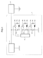
- Fig. 1 is an explanatory diagram for illustrating an example of a configuration of the power supply system according to first to third embodiments and fourth to fifteenth embodiments.
- a power supply system 7 shown in Fig. 1 is, for example, an in-car cell starter power supply.
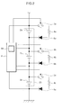
- Fig. 2 is an enlarged view showing an assembled battery, switches, resistors, diodes and a controller of the power supply system 7 shown in Fig. 1 .
- the power supply system 7 has a power generator 1, an assembled battery 20 in which cells 2a, 2b and 2c are connected in series, a plurality of forced discharge units capable of causing the cells 2a, 2b and 2c to forcibly discharge individually, and a controller 6 that measures voltage of the cells 2a, 2b and 2c individually and, when the voltage of the cells reaches the forced discharge start voltage Va, uses the forced discharge units to cause the cells to forcibly discharge individually until the voltage thereof reaches the forced discharge end voltage Vb.
- the plurality of the cells may be connected in parallel.
- the controller 6 is a control circuit that is configured by, for example, a voltage detection circuit 61 (cell state detector), microcomputer, logic circuit, and the like.
- the voltage detection circuit 61 is configured by, for example, an AD (analog/digital) converter for detecting the terminal voltage of each of the cells 2a, 2b and 2c, a comparator, and the like.
- each of the forced discharge units has a forced discharge circuit and switches 3a, 3b and 3c for connecting the cells 2a, 2b and 2c to the forced discharge circuit on the basis of a command from the controller 6.
- the forced discharge circuit has resistors 4a, 4b and 4c and diodes 5a, 5b and 5c.
- the switches 3a, 3b and 3c are each configured by a switching element, such as FET (Field Effect Transistor).
- the number of cells may not be limited to three and therefore may be the same as the number of resistors, diodes or switches.
- a series circuit of the switch 3a, the resistor 4a and the diode 5a is connected to the cell 2a in parallel.
- a series circuit of the switch 3b, the resistor 4b and the diode 5b is connected to the cell 2b in parallel.
- a series circuit of the switch 3c, the resistor 4c and the diode 5c is connected to the cell 2c in parallel.
- the cathodes of the diodes 5a, 5b and 5c are connected to the negative electrodes of the cells 2a, 2b and 2c respectively.
- an in-car device 8 an example of a load, is connected to the power supply system 7.
- the in-car device 8 is a load device, such as a cell starter for starting the engine of a vehicle, a light, a car navigation device, or the like.
- the positive electrode of the assembled battery 20, which is the positive electrode of the cell 2a, is connected to the in-car device 8, whereby discharging current of the assembled 20 is supplied to the in-car device 8.
- the power generator 1 is, for example, a constant-voltage power generator that is installed in a vehicle and generates power by means of the rotational motion of the engine.
- a voltage output terminal of the power generator 1 is connected to the positive electrode of the cell 2a and the in-car device 8.
- the assembled battery and the in-car device 8 are connected in parallel as viewed from the power generator 1.
- Voltage generated by the power generator 1 is parallely supplied to the assembled battery 20 and the in-car device 8.
- a constant-voltage power generator is used as the power generator 1 and a nonaqueous electrolyte secondary battery (i.e. a lithium ion secondary battery) is used as each of the cells 2a, 2b and 2c.
- a nonaqueous electrolyte secondary battery i.e. a lithium ion secondary battery
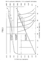
- Fig. 3 is an explanatory diagram showing an example of an initial charge-discharge behavior that is obtained when a lithium ion secondary battery having lithium cobaltate as a positive-electrode active material and black lead as a negative-electrode active material is charged by a constant-voltage power generator.
- the graph showing that regular voltage per cell is 3.8V is represented by a letter A
- the graph showing 3.9V as the regular voltage by a letter B the graph showing 4.0V as the regular voltage by a letter C
- the graph showing 4.1V as the regular voltage by a letter D
- the graph showing 4.2V as the regular voltage by a letter E the graph showing that regular voltage per cell is 3.8V is represented by a letter A
- the graph showing 3.9V as the regular voltage by a letter B the graph showing 4.0V as the regular voltage by a letter C
- the graph showing 4.1V as the regular voltage by a letter D the graph showing 4.2V as the regular voltage by a letter E.
- the power generator 1 charges the lithium ion secondary battery at constant current until the voltage thereof reaches the regular voltage, and charges the lithium ion secondary battery at constant voltage while attenuating the current.
- SOC a value obtained by dividing a charging capacity where the regular voltage per cell is 3.9V by a charging capacity where the regular voltage per cell is 4.2V
- the SOC becomes 91%.
- Table 1 shows the relationship between the regular voltage (terminal voltage of each cell) of the power generator per lithium ion secondary battery (cell) and the SOC on the basis of Fig. 3 .
- the electrolyte component mainly carbonate
- the forced discharge start voltage Va is set at voltage slightly lower than the voltage that shows that the SOC is approximately 100% after charging, and at the same time the controller 6 measures the voltages of the individual lithium ion secondary batteries successively.
- the cells are caused to forcibly discharge by forced discharge units on the basis of a command from the controller 6 until the voltage of the corresponding reaches the forced discharge end voltage Vb.
- the controller 6 uses the voltage detection circuit 61 to measure, successively and individually, the voltages of the cells 2a, 2b and 2c configuring the assembled battery 20. Charging current is supplied irregularly from the power generator 1 to the assembled battery 20.
- the switch 3 a is turned on while the switches 3b and 3c stay off, based on a command from the controller 6.
- the switch 3a is turned off based on a command from the controller 6 so that the cell 2a is ready to be charged by the power generator 1.
- the terminal voltages of the cells 2b and 2c are less than the forced discharge start voltage Va, the battery capacity is sufficient, and the cell 2b,2c are ready to be charged by the power generator 1. Therefore, it is possible to avoid a situation where the charging current cannot be absorbed by the assembled battery 20 and is supplied excessively to the in-car device 8. Furthermore, even when the terminal voltage of the cell 2b or 2c reaches the forced discharge start voltage Va and thereby forced discharge thereof is started after the forced discharge of the cell 2a is finished, at least the cell 2a has sufficient battery capacity from the previous forced discharge. Hence, the cell 2a becomes ready to be charged by the power generator 1 and, as a result, the charging current is prevented from being supplied excessively to the in-car device 8.
- a power supply system uses, according to the power supply system according to the third embodiment, a lithium composite oxide that contains cobalt as the positive-electrode active material of the nonaqueous electrolyte secondary battery.
- a lithium composite oxide having lithium cobaltate or other cobalt as the positive-electrode active material, discharge voltage of the nonaqueous electrolyte secondary battery rises and the energy density increases easily.
- the forced discharge start voltage Va (voltage showing the first state) is set to at least 4.05V but no more than 4.15V for one cell.
- the forced discharge start voltage Va it is not preferable to set the forced discharge start voltage Va at voltage less than 4.05V per cell, because the charge acceptable amount of the cell becomes excessively small.
- the forced discharge end voltage Vb (voltage showing the second state) is set to at least 3.85V but no more than 3.95V per cell.
- the forced discharge end voltage Vb it is not preferable to set the forced discharge end voltage Vb at voltage less than 3.85V per cell, because the amount of electricity for forced discharge becomes excessively high (the time for each forced discharge increases), and charging current from a charger 1 is accepted by a small number of cells at all times.
- the first state is a state where the state of charge of each cell is within the range of 86.5% to 95.5%
- the second state is a state where the state of charge of each cell is within the range of 68.5% to 77.5%.
- the amount of electricity required for the forced discharge is calculated from the forced discharge start voltage Va and the forced discharge end voltage Vb, and the forced discharge is carried out with a constant current value for a constant period of time.
- the controller uses the forced discharge units to cause the cell, whose voltage becomes the forced discharge start voltage Va, to discharge a previously set amount of discharge electricity with a previously set constant current value for a previously set constant period of time, the set amount of discharge electricity being set as an amount of discharge electricity for reducing the voltage of the cell from the forced discharge start voltage Va to the forced discharge end voltage Vb.
- the forced discharge is continued regardless of the drop of the voltage of the cells. Therefore, the cell having a greater state of charge than the other cells can be caused to discharge more than the other cells by the set amount of discharge electricity, so that the imbalance can be reduced more reliably.
- the cells 2a, 2b and 2c can be caused to discharge at constant current via the resistors 4a, 4b and 4c by turning the switches 3a, 3b and 3c on.
- the cell state detector detects the voltage of each cell as the state of the cell.
- the first state is a state where the voltage of the cell becomes the forced discharge start voltage Va that is set in advance to be lower than voltage obtained when the cell is fully charged
- the second state is a state where the voltage of the cell becomes the forced discharge end voltage Vb that is set in advance to be lower than the forced discharge start voltage Va.
- the controller may turn on the switch connected with the forced discharge circuit that is connected in parallel with the cell having the forced discharge start voltage Va, during a set time period that is set in advance as a time period for reducing the voltage of the cell from the forced discharge start voltage Va to the forced discharge end voltage Vb by turning the switch on.
- the switches 3a, 3b and 3c are turned on, although the cells 2a, 2b and 2c are caused to discharge at substantially constant current, the discharge current decreases due to the drop of the voltage caused by the discharge. Therefore, the discharging current is not necessarily constant.
- the switches 3a, 3b and 3c are turned on, and the time required for reducing the voltage of the cells 2a, 2b and 2c from the forced discharge start voltage Va to the forced discharge end voltage Vb is experimentally measured in advance. This time is used as the set time period so that the forced discharge can be carried out more accurately.
- the controller 6 controls the time such that, for example, the forced discharge for the amount of electricity is carried out for 54 minutes at 5-hour rate regardless of whether charge is performed from the power generator or discharge is performed to the in-car device, whereby the cell can be caused to forcibly discharge simply and reliably.
- This aspect is effective when discharge is performed to the in-car device 8 at large current and consequently closed circuit voltage drops drastically (voltage that is extremely lower than open circuit voltage corresponding to the actual SOC of the cell due to the resistance of the cell).
- the forced discharge is performed while successively measuring the voltages until the voltage of the cell reaches 3.9V
- the terminal voltage drops to 3.9V due to large-current discharge to the in-car device 8 during the forced discharge of the cell
- the forced discharge might end although the forced discharge is not performed on the cell sufficiently.
- the set amount of discharge electricity that is previously set at the amount of discharge electricity for reducing the voltage of the cell from the forced discharge start voltage Va to the forced discharge end voltage Vb is discharged by control of the time.
- the set amount of discharge electricity is discharged and a sufficient amount of electricity for accepting charge can be secured.
- a power supply system has: an assembled battery in which a plurality of cells are connected in series and which supplies power from a series circuit of the cells to a device; a power generator that parallely supplies generated power to the assembled battery and the device connected in parallel; a plurality of forced discharge units that cause the plurality of cells to forcibly discharge individually; a cell state detector that detects a state of each cell; and a controller which, when the cell state detector detects that at least one of the plurality of cells is in a first state showing that the cell is not fully charged, causes the cell detected to be in the first state to discharge by means of the forced discharge units until the cell state detector detects that the cell enters a second state having a lower state of charge than the first state.
- the power supply system is also a power supply system that has an assembled battery having a combination of a plurality of cells and a power generator capable of charging the assembled battery, the power supply system further having a plurality of forced discharge units capable of causing the cells to forcibly discharge individually, and a controller which, when the state of charge of the individually grasped cells reaches a forced discharge start state Ca, uses the forced discharge units to cause the cells to forcibly discharge individually until the state of charge of reaches a forced discharge end state Cb.
- the cell state detector detects the state of charge of each cell as the state of each cell.
- the first state is a state where the state of charge of the cell becomes the forced discharge start state Ca that is previously set at the state of charge showing that the cell is not fully charged.
- the second state is a state where the state of charge of the cell becomes the forced discharge end state Cb that is previously set as the state of charge less than the forced discharge start state Ca.
- the forced discharge start state Ca is set at the state of charge showing that the cell is not fully charged. Then, excess power exceeding power consumption of the device is charged to the assembled battery by the power generator, and when the cell state detector detects that the state of charge of the cell reaches the forced discharge start state Ca, the cell whose state of charge reaches the forced discharge start state Ca is caused to discharge by the forced discharge units until the state of charge drops to the forced discharge end state Cb.
- the cell state detector detects not the state of charge of each cell indirectly from the terminal voltage of each cell, but the state of charge of each cell directly from the terminal voltage. Therefore, the controller can improve the accuracy of control of a discharging operation performed by the forced discharge units.
- the state of charge of the cell is calculated from an initial charge behavior.
- the cell state detector has a current detector for detecting charging/discharging current flowing through each cell, and a charge state calculator for calculating the state of charge of each cell by cumulatively adding the charging current and subtracting the discharging current, for each of the cells, the charging current and the discharging current being detected by the current detector.
- the current detector further has a plurality of current detection resistors that are connected with the plurality of cells in series, and a current signal detector that acquires voltage between both ends of each of the current detection resistors as a signal indicating charging/discharging current flowing to each cell.
- the forced discharge circuits are respectively connected in parallel to a plurality of series circuits configured by the cell and the current detection resistor.
- the current signal detector acquires the voltage between both ends of each current detection resistor as the signal showing the charging/discharging current flowing to each cell, whereby the charging/discharging current flowing to each cell can be detected.
- a power supply system is, according to the power supply system of the eighth or ninth embodiment, configured by a forced discharge circuit composed of a resistor and a diode, and a switch connecting the cell with the forced discharge circuit on the basis of a command from the controller.
- a nonaqueous electrolyte secondary battery is used as each cell.
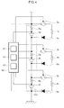
- Fig. 4 is an enlarged view showing an assembled battery 20a, switches 3a, 3b and 3c, resistors 4a, 4b and 4c, diodes 5a, 5b and 5c, current detection resistors Ra, Rb and Rc, and a controller 6a of the power supply system according to any one of the eighth to fifteenth embodiments.
- the assembled battery 20a and controller 6a shown in Fig. 4 are structurally different from the assembled battery 20 and controller 6 shown in Fig. 2 .
- the other configurations of the power supply system according to the eighth to fifteenth embodiments are the same as those of the power supply system 7 shown in Fig. 1 , and hence the description thereof is omitted.
- the current detection resistor Ra and the cell 2a are connected in series, and the cell 2a is connected with the cell 2b in series via the current detection resistor Rb.
- the cell 2b is connected with the cell 2c in series via the current detection resistor Rc.
- the current detection resistors Ra, Rb and Rc are so-called shunt resistors.
- the series circuit configured by the current detection resistor Ra and the cell 2a is connected in parallel to a series circuit of the switch 3a, resistor 4a and diode 5a.
- a series circuit configured by the current detection resistor Rb and cell 2b is connected in parallel with a series circuit configured by the switch 3b, resistor 4b and diode 5b.
- a series circuit of the current detection resistor Rc and cell 2c is connected in parallel with a series circuit of the switch 3c, resistor 4c and diode 5c.
- the controller 6a shown in Fig. 4 further has a current signal detector 62 and a charge state calculator 63.
- the current detection resistors Ra, Rb and Rc and the current signal detector 62 correspond to an example of the current detector.
- the current signal detector 62 is configured by an AD converter that converts the voltage between both ends of each of the current detection resistors Ra, Rb and Rc into a digital value.
- a microcomputer of the controller 6a functions as the charge state calculator 63 by executing a predetermined control program.
- the controller 6a uses a ROM (Read Only Memory) or other storage element to store a LUT (Look Up Table) that associates the terminal voltage of each of the cells 2a, 2b and 2c with SOC.
- ROM Read Only Memory
- LUT Look Up Table
- the controller 6a When the controller 6a is activated by connecting the assembled battery 20a with the controller 6a at the time of manufacture, the controller 6a acquires the terminal voltage of each of the cells 2a, 2b and 2c detected by the voltage detection circuit 61. The controller 6a then refers to the LUT and converts the terminal voltage of each of the cells 2a, 2b and 2c into the SOC of each of the cells 2a, 2b and 2c.
- the charge state calculator 63 stores thus obtained SOC in, for example, a RAM (Random Access Memory), EEPROM (Electrically Erasable and Programmable Read Only Memory) or other storage element, as an initial value of the SOC of each of the cells 2a, 2b and 2c.
- the charge state calculator 63 thereafter calculates the state of charge of the cells 2a, 2b and 2c by cumulatively adding the charging current and subtracting the discharging current for each of the cells 2a, 2b and 2c, the charging current and the discharging current being detected by the current signal detector 62.
- the nonaqueous electrolyte secondary battery such as a lithium ion secondary battery repeats charge/discharge
- the relationship between charging voltage and SOC tends to change due to deterioration of the positive-electrode or negative-electrode active material. Therefore, when the beginning and the end of the forced discharge are controlled by the abovementioned controller 6 on the basis of the forced discharge start voltage Va and the forced discharge end voltage Vb, the forced discharge might be started or ended at the state of charge different from the intended state of charge.
- the initial SOC of each of the cell 2a, 2b and 2c is stored in the controller 6a in association with (Table 1), and the SOCs of the cells 2a, 2b and 2c are successively obtained based on the amount of charge/discharge electricity integrated from the initial value.
- the switches 3a, 3b and 3c and the resistors 4a, 4b and 4c forced discharge units to cause the cells 2a, 2b and 2c to forcibly discharge individually until the state of charge reaches the forced discharge end state Cb.
- charge/discharge of the cells 2a, 2b and 2c can be carried out based on the SOC calculated regardless of a change in the relationship between the terminal voltage and SOC that is caused by a repetition of charge/discharge. Therefore, it is possible to improve the accuracy of maintaining the state of charge of each of cells 2a, 2b and 2c at the intended state of charge, that is, the state of charge at which charge from the power generator 1 can be accepted sufficiently.
- the configuration and the operation of the power supply system of the eighth to tenth embodiments are the same as the configuration and the operation of the power supply system of the first and second embodiments, except for the difference in control between the controller 6 and the controller 6a (the fact that the timing for starting or ending the forced discharge is set using a SOC value) and the fact that the current detection resistors Ra, Rb and Rc are added.
- examples of a method for calculating the SOC include a method for successively reading charging/discharging current values from the shunt resistors corresponding respectively to the cells 2a, 2b and 2c, transmitting to the controller 6a the read charging/discharging current values, integrating the amounts of charge/discharge electricity, and converting the result into SOC.
- a lithium composite oxide that contains cobalt is used as a positive-electrode active material of the nonaqueous electrolyte secondary battery.
- the configuration and effects of the power supply system according to the twelfth embodiment are the same as those of the power supply system according to the fourth embodiment.
- a power supply system is, according to the power supply system of any one of the eighth to twelfth embodiments, a power supply system in which the forced discharge start state Ca is set to at least 86.5% but no more than 95.5% per cell.
- the forced discharge start state Ca it is not preferable to set the forced discharge start state Ca atvalue less than 86.5%, because the charge acceptable amount of the cell becomes excessively small. Further, it is also not preferable to set the forced discharge start state at value exceeding 95.5% per cell, because forced discharge of the cell cannot be started until the state of charge reaches an overcharge region.
- a power supply system is, according to the power supply system of any one of the eighth to thirteenth embodiments, a power supply system in which the forced discharge end state Cb is set to at least 68.5% but no more than 77.5% per cell.
- the forced discharge end state Cb is set to at least 68.5% but no more than 77.5% per cell.
- a power supply system is, according to the power supply system of any one of the eighth to fourteenth embodiments, is a power supply system in which the amount of electricity required for the forced discharge is calculated from the forced discharge start state Ca and the forced discharge end state Cb, and the forced discharge is carried out with a constant current value for a constant period of time.
- the controller uses the forced discharge units to cause the cell, whose state of charge becomes the forced discharge start state Ca, to discharge a previously set amount of discharge electricity with a previously set constant current value for a previously set constant period of time, the set amount of discharge electricity being set as an amount of discharge electricity for reducing the state of charge of the cell from the forced discharge start state Ca to the forced discharge end state Cb.
- the forced discharge is continued regardless of the amount of charge/discharge of the cell. Therefore, the cell having a greater state of charge than the other cells can be caused to discharge more than the other cells by the set amount of discharge electricity, so that the imbalance can be reduced more reliably.
- the switches 3a, 3b and 3c shown in Fig. 4 when the switches 3a, 3b and 3c shown in Fig. 4 are turned on, the cells 2a, 2b and 2c can be caused to discharge at substantially constant current via the resistors 4a, 4b and 4c.
- the cell state detector detects the state of charge of each cell as the state of each cell.
- the first state is a state where the state of charge of the cell becomes the forced discharge start state Ca that is previously set at the state of charge at which the cell is not fully charged.
- the second state is a state where the state of charge of the cell becomes the forced discharge end state Cb that is previously set as the state of charge less than the forced discharge start state Ca.
- the controller turns on the switch connected with the forced discharge circuit that is connected in parallel with the cell having the forced discharge start state Ca, during a set time period that is set in advance as a time period for reducing the state of charge of the cell from the forced discharge start state Ca to the forced discharge end state Cb by turning the switch on.
- the switches 3a, 3b and 3c are turned on, although the cells 2a, 2b and 2c are caused to discharge at substantially constant current, the discharge current decreases due to the drop of the voltage caused by the discharge. Therefore, the discharging current is not necessarily constant.
- the switches 3a, 3b and 3c are turned on, and the time required for reducing the state of charge of the cells 2a, 2b and 2c from the forced discharge start state Ca to the forced discharge end state Cb is experimentally measured in advance. This time is used as the set time period so that the forced discharge can be carried out more accurately.
- the controller 6 controls the time such that, for example, the forced discharge for the amount of electricity is carried out for 54 minutes at 5-hour rate regardless of whether charge is performed from the power generator or discharge is performed to the in-car device, whereby the cell can be caused to forcibly discharge simply and reliably.
- a control method of an assembled battery according to a sixteenth embodiment is a control method of an assembled battery having a combination of a plurality of cells, wherein when an individually measured voltage of each cell reaches the forced discharge start voltage Va, the cells are caused to forcibly discharge individually until the voltage of each cell reaches the forced discharge end voltage Vb.
- the method is a control method of an assembled battery for supplying power to a device from an assembled battery having a plurality of cells connected in series, the control method having: a step in which a power generator parallely supplies generated power to the assembled battery and the device; a step in which a cell state detector detects a state of each cell; and a step in which, when the cell state detector detects that at least one of the plurality of cells is in a first state showing that the cell is not fully charged, a controller causes the cell detected to be in the first state to discharge by means of a forced discharge unit until the cell state detector detects that the cell enters a second state having a lower state of charge than the first state.
- a control method of an assembled battery according to a seventeenth embodiment is, according to the control method of an assembled battery of the sixteenth embodiment, a method for performing forced discharge by using a forced discharge circuit configured by a resistor and a diode, and a switch that connects the cells with the forced discharge circuit on the basis of a forced discharge command.
- the configuration and effects of the control method of an assembled battery according to the seventeenth embodiment are the same as those described in the second embodiment.
- a control method of an assembled battery according to an eighteenth embodiment is, according to the control method of an assembled battery of the sixteenth or seventeenth embodiment, a method in which a nonaqueous electrolyte secondary battery is used as each cell.
- the configuration and effects of the control method of an assembled battery according to the eighteenth embodiment are the same as those described in the third embodiment.
- a control method of an assembled battery according to a nineteenth embodiment is, according to the control method of an assembled battery of the eighteenth embodiment, a method that uses a lithium composite oxide that contains cobalt as the positive-electrode active material of the nonaqueous electrolyte secondary battery.
- the configuration and effects of the control method of an assembled battery according to the nineteenth embodiment are the same as those described in the fourth embodiment.
- a control method of an assembled battery according to a twentieth embodiment is, according to the control method of an assembled battery of the eighteenth or nineteenth embodiment, a method in which the forced discharge start voltage Va is set to at least 4.05V but no more than 4.15V per cell.
- the configuration and effects of the control method of an assembled battery according to the twentieth embodiment are the same as those described in the fifth embodiment.
- a control method of an assembled battery according to a twenty-first embodiment is, according to the control method of an assembled battery of any one of the eighteenth to twentieth embodiments, a method in which the forced discharge end voltage Vb is set to at least 3.85V but no more than 3.95V per cell.
- the configuration and effects of the control method of an assembled battery according to the twenty-first embodiment are the same as those described in the sixth embodiment.
- a control method of an assembled battery according to a twenty-second embodiment is, according to the control method of an assembled battery of any one of the sixteenth to twenty-first embodiments, a method for calculating the amount of electricity required for forced discharge, from the forced discharge start voltage Va and the forced discharge end voltage Vb, and carrying out the forced discharge with a constant current value for a constant period of time.
- the configuration and effects of the control method of an assembled battery according to the twenty-second embodiment are the same as those described in the seventh embodiment.
- a control method of an assembled battery according to a twenty-third embodiment is a control method of an assembled battery having a combination of a plurality of cells, wherein, when individually understood state of charge of each cell reaches the forced discharge start state Ca, the cells are caused to forcibly discharge individually until the state of charge thereof reaches the forced discharge end state Cb.
- the configuration and effects of the control method of an assembled battery according to the twenty-third embodiment are the same as those described in the eighth embodiment.
- a control method of an assembled battery according to a twenty-fourth embodiment is, according to the control method of an assembled battery of the twenty-third embodiment, a method for calculating the state of charge of each cell from an initial charge behavior.
- the configuration and effects of the control method of an assembled battery according to the twenty-fourth embodiment are the same as those described in the ninth embodiment.
- a control method of an assembled battery according to a twenty-fifth embodiment is, according to the control method of an assembled battery of the twenty-third or twenty-fourth embodiment, a method for performing forced discharge by using a forced discharge circuit configured by a resistor and a diode, and a switch that connects the cells with the forced discharge circuit on the basis of a forced discharge command.
- the configuration and effects of the control method of an assembled battery according to the twenty-fifth embodiment are the same as those described in the tenth embodiment.
- a control method of an assembled battery according to a twenty-sixth embodiment is, according to the control method of an assembled battery of any one of the twenty-third to twenty-fifth embodiments, a method in which a nonaqueous electrolyte secondary battery is used as each cell.
- the configuration and effects of the control method of an assembled battery according to the twenty-sixth embodiment are the same as those described in the eleventh embodiment.
- a control method of an assembled battery according to a twenty-seventh embodiment is, according to the control method of an assembled battery of the twenty-sixth embodiment, a method that uses a lithium composite oxide that contains cobalt as the positive-electrode active material of the nonaqueous electrolyte secondary battery.
- the configuration and effects of the control method of an assembled battery according to the twenty-seventh embodiment are the same as those described in the twelfth embodiment.
- a control method of an assembled battery according to a twenty-eighth embodiment is, according to the control method of an assembled battery of any one of the twenty-third to twenty-seventh embodiments, a method in which the forced discharge start state Ca is set to at least 86.5% but no more than 95.5% per cell.
- the configuration and effects of the control method of an assembled battery according to the twenty-eighth embodiment are the same as those described in the thirteenth embodiment.
- a control method of an assembled battery according to a twenty-ninth embodiment is, according to the control method of an assembled battery of any one of the twenty-third to twenty-eighth embodiments, a method in which the forced discharge end state Cb is set to at least 68.5% but no more than 77.5% per cell.
- the configuration and effects of the control method of an assembled battery according to the twenty-ninth embodiment are the same as those described in the fourteenth embodiment.
- a control method of an assembled battery according to a thirtieth embodiment is, according to the control method of an assembled battery of any one of the twenty-third to twenty-ninth embodiments, a method for calculating the amount of electricity required for forced discharge, from the forced discharge start state Ca and the forced discharge end state Cb, and carrying out the forced discharge with a constant current value for a constant period of time.
- the configuration and effects of the control method of an assembled battery according to the thirtieth embodiment are the same as those described in the fifteenth embodiment.
- nonaqueous electrolyte secondary battery specifically, a lithium ion secondary battery
- a lithium ion secondary battery is sued as each cell
- the same results are achieved by using, from among nonaqueous electrolyte secondary batteries, a lithium polymer secondary battery with a gel-like electrolyte or an alkaline storage battery, a nickel-hydrogen storage battery, or a nickel-cadmium storage battery, as each cell.
- a power supply system has an assembled battery having a combination of a plurality of cells, a power generator capable of charging the cells, a plurality of forced discharge units capable of causing the cells to forcibly discharge individually, and a controller which, when individually measured voltage of each cell reaches a forced discharge start voltage Va (or when the state of charge of individually understood cell reaches a forced discharge start state Ca), uses the forced discharge units to cause the cells to forcibly discharge until the voltage reaches a forced discharge end voltage Vb (or a forced discharge end state Cb).
- a control method is a control method of an assembled battery having a combination of a plurality of cells, wherein, when individually measured voltage of each cell reaches the forced discharge start voltage Va (or when individually measured state of charge of each cell reaches the forced discharge start state Ca), the forced discharge units are used to cause the cells to forcibly discharge until the voltage reaches the forced discharge end voltage Vb (or the forced discharge end state Cb).
- any of the plurality of cells needs to be ready to accept the charge.
- the variation of SOC between the cells does not need to be concerned or taken into consideration.
- the present invention has been contrived in view of an assembled battery used in such environment, and in the present invention, when the voltage of each cell reaches the forced discharge start voltage Va (or when the state of charge of individually understood cell reaches the forced discharge start state Ca), the cell is caused to discharge until it reaches a charge acceptable state (in which the voltage reaches approximately the forced discharge end voltage Vb or the SOC reaches approximately the forced discharge end state Cb), so as to prepare to receive charge from the power generator.
- a charge acceptable state in which the voltage reaches approximately the forced discharge end voltage Vb or the SOC reaches approximately the forced discharge end state Cb
- the power supply system and a control method of an assembled battery according to the present invention can be used in a variety of devices that uses an assembled battery, and provide a high degree of usability especially in a cell starter power supply of a racing car.
Landscapes
- Engineering & Computer Science (AREA)
- Power Engineering (AREA)
- Manufacturing & Machinery (AREA)
- Chemical & Material Sciences (AREA)
- Chemical Kinetics & Catalysis (AREA)
- Electrochemistry (AREA)
- General Chemical & Material Sciences (AREA)
- Charge And Discharge Circuits For Batteries Or The Like (AREA)
- Secondary Cells (AREA)
Applications Claiming Priority (2)
| Application Number | Priority Date | Filing Date | Title |
|---|---|---|---|
| JP2007152305 | 2007-06-08 | ||
| PCT/JP2007/069162 WO2008149475A1 (ja) | 2007-06-08 | 2007-10-01 | 電源システムおよび組電池の制御方法 |
Publications (2)
| Publication Number | Publication Date |
|---|---|
| EP2157657A1 true EP2157657A1 (de) | 2010-02-24 |
| EP2157657A4 EP2157657A4 (de) | 2011-09-28 |
Family
ID=40093310
Family Applications (1)
| Application Number | Title | Priority Date | Filing Date |
|---|---|---|---|
| EP07828902A Withdrawn EP2157657A4 (de) | 2007-06-08 | 2007-10-01 | Stromsystem und steuerverfahren für zusammengebaute batterien |
Country Status (6)
| Country | Link |
|---|---|
| US (1) | US20100253284A1 (de) |
| EP (1) | EP2157657A4 (de) |
| JP (1) | JPWO2008149475A1 (de) |
| KR (1) | KR20100033509A (de) |
| CN (1) | CN101682091B (de) |
| WO (1) | WO2008149475A1 (de) |
Cited By (3)
| Publication number | Priority date | Publication date | Assignee | Title |
|---|---|---|---|---|
| ITBO20100209A1 (it) * | 2010-04-07 | 2011-10-08 | Ferrari Spa | Impianto elettrico di un veicolo stradale con propulsione elettrica e relativo metodo di controllo |
| EP2690743A1 (de) * | 2011-03-25 | 2014-01-29 | NEC Energy Devices, Ltd. | Energiespeichersystem und verfahren zur steuerung einer wiederaufladbaren batterie |
| EP2879266A1 (de) * | 2013-11-28 | 2015-06-03 | Dialog Semiconductor GmbH | Leistungsverwaltungsverfahren für eine wiederaufladbare Stapelzellen-Energiespeichereinrichtung und wiederaufladbare Stapelzellen-Energiespeichereinrichtung |
Families Citing this family (36)
| Publication number | Priority date | Publication date | Assignee | Title |
|---|---|---|---|---|
| US8354824B2 (en) | 2009-05-08 | 2013-01-15 | Robert Bosch Gmbh | System and method for charging and discharging a Li-ion battery pack |
| JP2011090873A (ja) * | 2009-10-22 | 2011-05-06 | Hitachi Vehicle Energy Ltd | 扁平形二次電池モジュール |
| JP2011130551A (ja) * | 2009-12-16 | 2011-06-30 | Sanyo Electric Co Ltd | 電源装置及びこれを備える車両 |
| US20120274284A1 (en) * | 2010-01-05 | 2012-11-01 | A123 Systems, Inc. | System and Method for Controlling Voltage of Individual Battery Cells Within a Battery Pack |
| US9991551B2 (en) * | 2010-02-04 | 2018-06-05 | Gs Yuasa International Ltd. | Assembled battery, method of charging an assembled battery, and charging circuit which charges an assembled battery |
| CN102754271B (zh) * | 2010-02-04 | 2015-07-01 | 株式会社杰士汤浅国际 | 充电方法 |
| JP5664032B2 (ja) * | 2010-09-02 | 2015-02-04 | 日産自動車株式会社 | 双極型二次電池 |
| US8593110B2 (en) * | 2010-11-19 | 2013-11-26 | General Electric Company | Device and method of battery discharge |
| JP5801605B2 (ja) | 2011-05-16 | 2015-10-28 | ラピスセミコンダクタ株式会社 | 比較回路、半導体装置、電池監視システム、充電禁止方法、及び充電禁止プログラム |
| JP6106991B2 (ja) | 2011-09-09 | 2017-04-05 | 株式会社Gsユアサ | 状態管理装置、蓄電素子の均等化方法 |
| US20140232302A1 (en) * | 2011-09-26 | 2014-08-21 | Toyota Jidosha Kabushiki Kaisha | Battery processing apparatus, vehicle, battery processing method, and battery processing program |
| JP2013230003A (ja) * | 2012-04-25 | 2013-11-07 | Sanyo Electric Co Ltd | 電源装置、電源装置を備える車両及び蓄電装置並びに組電池の放電方法 |
| DE102012213926A1 (de) * | 2012-08-07 | 2014-02-13 | Robert Bosch Gmbh | Batteriemodul, Batteriemanagementsystem, System zur Versorgung eines Antriebs einer zur Drehmomenterzeugung geeigneten Maschine mit elektrischer Energie und Kraftfahrzeug |
| GB201216127D0 (en) * | 2012-09-11 | 2012-10-24 | Jaguar Cars | A method for determining the change in a vehicle battery |
| CN102916412B (zh) * | 2012-10-15 | 2016-01-20 | 艾维新能源科技南京有限公司 | 电池/电容组串联逃逸电路 |
| JP6026226B2 (ja) * | 2012-10-30 | 2016-11-16 | 株式会社日立情報通信エンジニアリング | 蓄電システム及び電源システム |
| DE102013204541A1 (de) * | 2013-03-15 | 2014-09-18 | Robert Bosch Gmbh | Batteriezelleinheit mit Batteriezelle und ultraschneller Entladeschaltung und Verfahren zur Überwachung einer Batteriezelle |
| KR101587472B1 (ko) * | 2013-05-08 | 2016-01-21 | 주식회사 엘지화학 | 배터리 예열 시스템 및 이를 이용한 배터리 예열방법 |
| JP2015002662A (ja) * | 2013-06-18 | 2015-01-05 | Fdk株式会社 | 二次電池の放電回路、バランス補正回路、及び蓄電装置 |
| WO2015011570A2 (en) * | 2013-07-23 | 2015-01-29 | Sis Resources, Ltd. | Charger for an electronic cigarette |
| CN103427651A (zh) * | 2013-07-25 | 2013-12-04 | 天津市松正电动汽车技术股份有限公司 | 一种车用供电系统及其工作方法 |
| JP6237425B2 (ja) * | 2014-04-09 | 2017-11-29 | トヨタ自動車株式会社 | 車両 |
| JP2015217692A (ja) * | 2014-05-14 | 2015-12-07 | トヨタ自動車株式会社 | 電源制御装置 |
| US20170092985A1 (en) * | 2014-06-05 | 2017-03-30 | Sony Corporation | Secondary battery-use electrolytic solution, secondary battery, battery pack, electric vehicle, electric power storage system, electric power tool, and electronic apparatus |
| KR102523045B1 (ko) * | 2016-01-12 | 2023-04-17 | 삼성전자주식회사 | 고장 셀 검출 장치 및 방법 |
| US20200303732A1 (en) * | 2016-03-31 | 2020-09-24 | Kaneka Corporation | Method for producing battery pack and method for manufacturing electricity storage device |
| CN105978065A (zh) * | 2016-05-12 | 2016-09-28 | Tcl移动通信科技(宁波)有限公司 | 一种移动终端反向供电输出电流设置方法及装置 |
| WO2018002412A1 (en) * | 2016-06-28 | 2018-01-04 | Kone Corporation | Power arrangement |
| KR102319239B1 (ko) * | 2016-12-21 | 2021-10-28 | 삼성에스디아이 주식회사 | 배터리 팩 |
| JP6973213B2 (ja) * | 2018-03-16 | 2021-11-24 | トヨタ自動車株式会社 | 二次電池システム、及び二次電池制御方法 |
| CN108550926A (zh) * | 2018-04-26 | 2018-09-18 | 奇瑞汽车股份有限公司 | 电池系统和电动汽车 |
| JP7044671B2 (ja) * | 2018-09-07 | 2022-03-30 | Fdk株式会社 | 蓄電装置及び充電方法 |
| KR20200102284A (ko) * | 2019-02-21 | 2020-08-31 | 주식회사 엘지화학 | Ess의 안정화 시스템 및 그 방법 |
| JP7100002B2 (ja) * | 2019-09-10 | 2022-07-12 | 矢崎総業株式会社 | 電池制御ユニットおよび電池システム |
| JP7051776B2 (ja) * | 2019-09-30 | 2022-04-11 | 矢崎総業株式会社 | 電池制御ユニットおよび電池システム |
| US20220355140A1 (en) * | 2021-05-05 | 2022-11-10 | Oshkosh Corporation | Operational modes for a driveline of an electrified fire fighting vehicle |
Citations (3)
| Publication number | Priority date | Publication date | Assignee | Title |
|---|---|---|---|---|
| JP2001178003A (ja) * | 1999-12-22 | 2001-06-29 | Hitachi Ltd | 組電池の電池電圧補正装置 |
| JP2002281687A (ja) * | 2001-03-21 | 2002-09-27 | Denso Corp | 充電状態制御方法及び装置 |
| US20030232237A1 (en) * | 2002-06-12 | 2003-12-18 | Nissan Motor Co,. Ltd. | Voltage control apparatus for battery pack |
Family Cites Families (16)
| Publication number | Priority date | Publication date | Assignee | Title |
|---|---|---|---|---|
| US3997830A (en) * | 1974-11-27 | 1976-12-14 | Rca Corporation | Satellite battery reconditioning system and method |
| US4313080A (en) * | 1978-05-22 | 1982-01-26 | Battery Development Corporation | Method of charge control for vehicle hybrid drive batteries |
| FR2438934A1 (fr) * | 1978-10-09 | 1980-05-09 | Accumulateurs Fixes | Dispositif de regulation de la charge d'une batterie d'accumulateurs |
| US5504415A (en) * | 1993-12-03 | 1996-04-02 | Electronic Power Technology, Inc. | Method and apparatus for automatic equalization of series-connected batteries |
| US6022640A (en) * | 1996-09-13 | 2000-02-08 | Matsushita Electric Industrial Co., Ltd. | Solid state rechargeable lithium battery, stacking battery, and charging method of the same |
| JPH11122840A (ja) * | 1997-10-13 | 1999-04-30 | Toyota Motor Corp | 二次電池制御装置 |
| JP3989107B2 (ja) * | 1998-07-27 | 2007-10-10 | 三洋電機株式会社 | 二次電池の充電量をバランスさせる方法 |
| JP3870577B2 (ja) * | 1998-09-14 | 2007-01-17 | 株式会社デンソー | 組電池のばらつき判定方法及びバッテリ装置 |
| JP3676134B2 (ja) * | 1998-11-30 | 2005-07-27 | 三洋電機株式会社 | 充放電制御方法 |
| JP2000166103A (ja) * | 1998-12-01 | 2000-06-16 | Sanyo Electric Co Ltd | 充放電制御方法 |
| JP4022797B2 (ja) * | 1999-03-29 | 2007-12-19 | 株式会社ジーエス・ユアサコーポレーション | 群電池の容量平準化回路 |
| CN100386941C (zh) * | 2001-03-30 | 2008-05-07 | 运输设计有限公司 | 蓄电池管理单元、系统和方法 |
| JP4065232B2 (ja) * | 2003-12-11 | 2008-03-19 | 三洋電機株式会社 | 電池の充電方法 |
| JP2005224013A (ja) * | 2004-02-05 | 2005-08-18 | Honda Motor Co Ltd | 電源装置 |
| JP4400536B2 (ja) * | 2004-12-27 | 2010-01-20 | 日産自動車株式会社 | 組電池の容量調整装置および容量調整方法 |
| US20070080664A1 (en) * | 2005-07-29 | 2007-04-12 | Ford Global Technologies, Llc | System and method for rebalancing a battery during vehicle operation |
-
2007
- 2007-10-01 US US12/663,630 patent/US20100253284A1/en not_active Abandoned
- 2007-10-01 EP EP07828902A patent/EP2157657A4/de not_active Withdrawn
- 2007-10-01 WO PCT/JP2007/069162 patent/WO2008149475A1/ja active Application Filing
- 2007-10-01 KR KR1020107000308A patent/KR20100033509A/ko not_active Application Discontinuation
- 2007-10-01 JP JP2009517689A patent/JPWO2008149475A1/ja not_active Withdrawn
- 2007-10-01 CN CN2007800532660A patent/CN101682091B/zh not_active Expired - Fee Related
Patent Citations (3)
| Publication number | Priority date | Publication date | Assignee | Title |
|---|---|---|---|---|
| JP2001178003A (ja) * | 1999-12-22 | 2001-06-29 | Hitachi Ltd | 組電池の電池電圧補正装置 |
| JP2002281687A (ja) * | 2001-03-21 | 2002-09-27 | Denso Corp | 充電状態制御方法及び装置 |
| US20030232237A1 (en) * | 2002-06-12 | 2003-12-18 | Nissan Motor Co,. Ltd. | Voltage control apparatus for battery pack |
Non-Patent Citations (1)
| Title |
|---|
| See also references of WO2008149475A1 * |
Cited By (7)
| Publication number | Priority date | Publication date | Assignee | Title |
|---|---|---|---|---|
| ITBO20100209A1 (it) * | 2010-04-07 | 2011-10-08 | Ferrari Spa | Impianto elettrico di un veicolo stradale con propulsione elettrica e relativo metodo di controllo |
| US9006920B2 (en) | 2010-04-07 | 2015-04-14 | Ferrari S.P.A. | Electrical system of a vehicle with electric propulsion and control method thereof |
| EP2374651A3 (de) * | 2010-04-07 | 2017-03-01 | FERRARI S.p.A. | Elektrisches System eines Fahrzeugs mit elektrischem Antrieb und Steuerverfahren dafür |
| EP2690743A1 (de) * | 2011-03-25 | 2014-01-29 | NEC Energy Devices, Ltd. | Energiespeichersystem und verfahren zur steuerung einer wiederaufladbaren batterie |
| EP2690743A4 (de) * | 2011-03-25 | 2014-10-22 | Nec Energy Devices Ltd | Energiespeichersystem und verfahren zur steuerung einer wiederaufladbaren batterie |
| US9368992B2 (en) | 2011-03-25 | 2016-06-14 | Nec Energy Devices, Ltd. | Power storage system and secondary battery control method |
| EP2879266A1 (de) * | 2013-11-28 | 2015-06-03 | Dialog Semiconductor GmbH | Leistungsverwaltungsverfahren für eine wiederaufladbare Stapelzellen-Energiespeichereinrichtung und wiederaufladbare Stapelzellen-Energiespeichereinrichtung |
Also Published As
| Publication number | Publication date |
|---|---|
| CN101682091B (zh) | 2012-07-25 |
| CN101682091A (zh) | 2010-03-24 |
| KR20100033509A (ko) | 2010-03-30 |
| EP2157657A4 (de) | 2011-09-28 |
| JPWO2008149475A1 (ja) | 2010-08-19 |
| US20100253284A1 (en) | 2010-10-07 |
| WO2008149475A1 (ja) | 2008-12-11 |
Similar Documents
| Publication | Publication Date | Title |
|---|---|---|
| EP2157657A1 (de) | Stromsystem und steuerverfahren für zusammengebaute batterien | |
| US9431850B2 (en) | Power supply unit having plurality of secondary batteries | |
| CN101803144B (zh) | 电源系统 | |
| US10008865B2 (en) | Energy storage device and method for operating it | |
| US7071653B2 (en) | Method for charging a non-aqueous electrolyte secondary battery and charger therefor | |
| EP2211399A1 (de) | Stromversorgungssystem | |
| JP2011015516A (ja) | 車載電源装置 | |
| KR20100119574A (ko) | 충전 제어 회로, 및 이것을 구비하는 충전 장치, 전지 팩 | |
| EP2207235A1 (de) | Stromversorgungssystem und steuerverfahren für zellanordnung | |
| KR20110104883A (ko) | 직류 전원 장치 | |
| EP2211416A1 (de) | Stromversorgungssystem und steuerverfahren für zellanordnung | |
| CN106956602B (zh) | 电池组和包括该电池组的电动车 | |
| JP2003134689A (ja) | 電源システム | |
| US20180097380A1 (en) | Energy storage apparatus for vehicle and vehicle | |
| WO2014068884A1 (ja) | 回生制動する車両の電源装置 | |
| JP3721690B2 (ja) | 2次電池の保護装置 | |
| JPH08140278A (ja) | 組電池の充放電保護装置 | |
| KR20120124540A (ko) | 자동차 스타팅 모터 구동용 스마트 배터리 | |
| CN116235381A (zh) | 电路控制方法、电池及其控制器和管理系统、用电装置 | |
| US11469600B2 (en) | Electrical energy store, device and method for operating an electrical energy store | |
| KR20240065016A (ko) | 차량 비상 시동 장치 및 그 제어 방법 | |
| UA155218U (uk) | Балансуючий зарядний пристрій для літій-іонних акумуляторних батарей | |
| JP2002010504A (ja) | 電気自動車の電源装置 | |
| CN116316935A (zh) | 电源管理方法及车辆辅助电源 | |
| CN117751478A (zh) | 电池系统的充放电方法及装置、电池系统与电动车辆 |
Legal Events
| Date | Code | Title | Description |
|---|---|---|---|
| PUAI | Public reference made under article 153(3) epc to a published international application that has entered the european phase |
Free format text: ORIGINAL CODE: 0009012 |
|
| 17P | Request for examination filed |
Effective date: 20091209 |
|
| AK | Designated contracting states |
Kind code of ref document: A1 Designated state(s): AT BE BG CH CY CZ DE DK EE ES FI FR GB GR HU IE IS IT LI LT LU LV MC MT NL PL PT RO SE SI SK TR |
|
| AX | Request for extension of the european patent |
Extension state: AL BA HR MK RS |
|
| DAX | Request for extension of the european patent (deleted) | ||
| A4 | Supplementary search report drawn up and despatched |
Effective date: 20110825 |
|
| RIC1 | Information provided on ipc code assigned before grant |
Ipc: H02J 7/34 20060101ALI20110819BHEP Ipc: H01M 10/44 20060101AFI20110819BHEP |
|
| 17Q | First examination report despatched |
Effective date: 20120613 |
|
| STAA | Information on the status of an ep patent application or granted ep patent |
Free format text: STATUS: THE APPLICATION IS DEEMED TO BE WITHDRAWN |
|
| 18D | Application deemed to be withdrawn |
Effective date: 20130502 |