EP2157491B1 - System zum Entfeuchten von Wänden - Google Patents
System zum Entfeuchten von Wänden Download PDFInfo
- Publication number
- EP2157491B1 EP2157491B1 EP20090167412 EP09167412A EP2157491B1 EP 2157491 B1 EP2157491 B1 EP 2157491B1 EP 20090167412 EP20090167412 EP 20090167412 EP 09167412 A EP09167412 A EP 09167412A EP 2157491 B1 EP2157491 B1 EP 2157491B1
- Authority
- EP
- European Patent Office
- Prior art keywords
- wall
- dehumidifying
- humidity
- unit
- control unit
- Prior art date
- Legal status (The legal status is an assumption and is not a legal conclusion. Google has not performed a legal analysis and makes no representation as to the accuracy of the status listed.)
- Revoked
Links
Images


Classifications
-
- E—FIXED CONSTRUCTIONS
- E04—BUILDING
- E04B—GENERAL BUILDING CONSTRUCTIONS; WALLS, e.g. PARTITIONS; ROOFS; FLOORS; CEILINGS; INSULATION OR OTHER PROTECTION OF BUILDINGS
- E04B1/00—Constructions in general; Structures which are not restricted either to walls, e.g. partitions, or floors or ceilings or roofs
- E04B1/62—Insulation or other protection; Elements or use of specified material therefor
- E04B1/70—Drying or keeping dry, e.g. by air vents
- E04B1/7007—Drying or keeping dry, e.g. by air vents by using electricity, e.g. electro-osmosis
-
- F—MECHANICAL ENGINEERING; LIGHTING; HEATING; WEAPONS; BLASTING
- F26—DRYING
- F26B—DRYING SOLID MATERIALS OR OBJECTS BY REMOVING LIQUID THEREFROM
- F26B25/00—Details of general application not covered by group F26B21/00 or F26B23/00
- F26B25/22—Controlling the drying process in dependence on liquid content of solid materials or objects
-
- G—PHYSICS
- G05—CONTROLLING; REGULATING
- G05D—SYSTEMS FOR CONTROLLING OR REGULATING NON-ELECTRIC VARIABLES
- G05D22/00—Control of humidity
- G05D22/02—Control of humidity characterised by the use of electric means
Definitions
- the object of the present invention is a system for monitoring and/or dehumidifying walls.
- the system that is the object of the invention consists of a plurality of different devices that together concur in the objective of dehumidifying the walls and keeping the state of health thereof under observation.
- Non-invasive solutions have also spread such as microwave dehumidifying systems, absorption dehumidification or also electrophysical dehumidification.
- a device is known from European Patent No. EP 928856 for dehumidifying and desalinating buildings in which a preset number of electromagnetic pulses are generated that act on the ions and on the salts dissolved in the water/humidity contained in the walls, promoting the migration of the latter ions to a return electrode that is generally placed on the ground and outside the building to be treated.
- a microcontroller is able to receive a plurality of signals coming from sensors arranged at the wall to be treated to analyse the signals and send corresponding command and control signals to the emission reel or to the return electrode to vary the distance between the pulses or the potential difference from the electrode so as to modify the intensity of the intervention.
- patent US 7173538 discloses a system that is able to generate information relating to a dehumidifying procedure and sending the information to a user via a suitable user interface.
- this system is able to transmit to a remote server data on the dehumidifying procedure measured by suitable sensors of various types and positioned at the structure to be treated, for example by exploiting Internet connections.
- the server transmits the information on the dehumidification procedure, which information is displayed and appropriately reprocessed via the user interface.
- a main object of the invention is to set up a coordinated system for monitoring and dehumidifying walls that is able to ensure optimum interventions on the affected walls of the building that are checkable in a accurate and repeatable manner. It is also an object of the wall monitoring and dehumidification system to enable the dehumidification procedures to be optimised in function of the chemical and physical environmental features and also in function of the procedural and operational needs that are required of the building (presence of frescoed walls, historical buildings, behaviour of the structure, ).
- 1 comprehensively indicates a system for monitoring and/or dehumidifying walls according to the invention.
- the system disclosed below consists of three different elements (each of which could be present in a number greater than one) and precisely of an electronic apparatus 2 for dehumidifying walls that is based on the electromagnetic or electrophysical principle ( figure 2 ) of a portable electronic apparatus 100 for detecting wall humidity ( figure 3 ) and of a fixed-installation electronic apparatus 200 for detecting wall humidity ( figure 4 ).
- the three apparatuses mentioned can be seen as devices in their own right with autonomous functions to be used singularly in well circumscribed circumstances but if used together they represent three subsystems of a modern and sought-after system for dehumidifying walls.
- the structure 2 for dehumidifying walls is illustrated in figure 2 .
- the structure 2 also comprises a means for dehumidifying walls 3 that is active for promoting the dehumidification of at least a wall portion.
- such a dehumidifying means 3 is an electromagnetic dehumidifying means comprising at least a solenoid valve traversed by a wave-shaped current with a particular and preset amplitude and frequency.
- the electromagnetic wave produced by the solenoid valve spreads in the surrounding space, modifying the behaviour of the water that rises by capillarity inside the walls.
- the action on the surface tension of the water is such as to reduce or eliminate the well-known rising effect. Natural evaporation is added to the reduction or elimination of rising by capillarity such that the wall dries and is consequently cured.
- the action of the apparatus 2 extends for a range of some metres around the installation point.
- a monitoring unit 4 is noted that is active on the dehumidifying means 3 to enable the operation thereof to be monitored.
- Suitable sensors such as an ambient temperature probe 81 and an ambient humidity probe 82 are slaved to the monitoring logic unit or microprocessor 4.
- the monitoring logic unit 4 is able to modify/adjust the monitoring parameters of the solenoid valve in a substantially continuous manner in order to modulate the efficacy of the intervention and of the dehumidification.
- the monitoring unit 4 is active on the wall-dehumidifying means 3 to vary the operating parameters thereof, for example by limiting or interrupting the operation thereof.
- the apparatus 2 comprises a memory 7 containing at least a desired dehumidifying profile and the monitoring unit 4 is active on the wall-dehumidifying means 3 to monitor the wall-dehumidifying means 3 in function of the set dehumidification profile.
- the apparatus 2 can be set by indicating the use of a particular sensor 200 (disclosed below) to be used as a feedback element to implement the monitoring of the dehumidifying profile that has just been mentioned.
- At least one of the plurality of apparatuses 2 that are usable in the system (but also all the apparatuses) has a communication module 5 that is suitable for at least receiving instructions from a remote unit 6 (such as, for example, a computer connected to the Internet or connected in another wireless manner to the aforementioned communication module 5).
- a remote unit 6 such as, for example, a computer connected to the Internet or connected in another wireless manner to the aforementioned communication module 5.
- the instructions are sent to the monitoring unit 4 to modify the operating modes of the apparatus 2 for dehumidifying walls.
- Such changes may consist of both a change to the operation of the means for dehumidifying walls, for example limitation thereof or interruption to operation, or may also be instructions to modify the dehumidifying profile stored in the memory 7 that the monitoring logic unit follows during the dehumidifying procedure.
- the communication module 5 is also suitable for transmitting information to the remote unit 6 relating to the operation of the apparatus 2.
- the information can, for example, relate to interrupting the supply, faults of different types or also operating data on the apparatus such as the set dehumidifying profile or the detected ambient temperatures and humidity and the charge level of the buffer battery.
- the communication module 5 can further transmit both at the request of the remote unit 6 and automatically when preset events occur such as exceeding preset alarm thresholds or also the elapsing of preset times.
- the communication module comprises a plurality of different modules having different functions.
- a remote wireless communication module 73 is above all present, for example a GSM module for sending and receiving data and instructions to and from the remote unit 6.
- a wireless module 74 for example a bidirectional module, can also be provided, in order to connect with the sensors or the apparatuses 200 for detecting wall humidity.
- a standard physical connection module 75 can be provided for connecting via cable to a PC or a terminal, for example an RS232/422 module.
- a Bluetooth module 76 can be further provided for standard connection to various further devices, which are also provided with a Bluetooth communication module.
- IRDA Infrared Data Association
- expansion slot 77 of standard type can also be provided.
- All the modules 73, 74, 75, 76 and 77 will be slaved to a reading/writing and monitoring bus 78 that is directly in communication with the monitoring logic unit 4.
- the apparatus 2 can inform the remote data gathering station of operating irregularities such as lack of power, empty batteries, faults, etc or also of the malfunction of one or more of the slaved wall sensors 200.
- a rechargeable battery 8 for example a rechargeable lithium battery
- the rechargeable battery 8 is slaved to a battery-charging unit 83 that also acts as a distribution unit for distributing supplies by in particular supplying the electromagnetic dehumidifying unit 3, the monitoring logic unit 4 and the various modules 73, 74, 75, 76 and 77 of the communication module 5.
- the system for monitoring and dehumidifying walls further comprises an apparatus (100) for detecting humidity at a given depth inside the wall, acting independently of the constituting material and of the type of construction of the wall.
- the apparatus (100) is a portable device that enables wall humidity to be detected in depth at the resting point on the wall.
- the measuring technique is based on detecting the dielectric constant of the material on which the device rests: the presence of water in fact causes a noticeable increase in the total value of the dielectric constant.
- the apparatus 100 further comprises a movable unit 11 defined by a box casing 28 that has at least one, and preferably two, lateral manual gripping members 29 that are suitable for permitting scanning movement along the wall surface 38.
- the gripping members are ring-shaped and arranged laterally on the movable unit 11 so that the scanning apparatus 100 can be grasped with both hands and a rear surface 39 thereof can rest on the wall surface 38 on which to conduct the detecting; the unit is then moved on the wall according to any direction, as shown by the arrows in figure 3b .
- such switches are arranged at the gripping members 29 in such a manner that it is possible to activate or stop the manually commanded detecting of humidity without removing any hand from the gripping member.
- the movable unit 11 is further provided with a suitable display for displaying a menu of possible operations, i.e. scanning data that exist or are detected by the sensors, as will be explained better.
- the apparatus 100 is advantageously provided with means 13 for detecting scanning coordinates that are suitable for determining the position of the movable unit 11 at least during detecting of humidity.
- Suitable means 12 for determining the wall humidity explained in greater detail below cooperates conjointly with such means 13 for detecting scanning coordinates.
- the apparatus 100 thus enables a humidity profile to be detected that is associated with the wall surface under examination, at a given depth (which can be varied) inside the wall.
- This in fact enables scanning on two dimensions to be conducted by sliding the sensible side (i.e. the rear surface 39) of the movable unit 11 along the wall surface 38.
- the aforesaid means 13 for detecting the scanning coordinates it will be possible to detect the movement of the movable unit 11 along the horizontal axis X and along the vertical axis Y.
- the instrument will store the precise humidity data, associating the humidity data with the coordinates, which are also precise.
- the internal memory of the instrument will contain the humidity map relating to the scanned surface.
- these data can be entered in a computer, which will be provided with a common display and with a microprocessor that will load a suitable software module that is suitable for displaying on the display a graphic representation of the detected humidity.
- the map that has just been detected will be displayed on the screen, providing a total vision of the state of humidity present on the wall surface or at a given depth below the wall surface.
- An additional software will be further present that is suitable for interpolating the detected humidity data to reconstruct the humidity profile in areas of the wall surface that are not subjected to scanning.
- the software installed on the PC will also represent, through the aforesaid interpolation, possible surface pieces that have escaped detection.
- this method enables maps detected on the same wall surface at different times to be compared, enabling a good assessment of the dehumidification of the wall achieved following focussed interventions (whether they be invasive or non-invasive).
- the means 13 for detecting comprises at least a coordinates reference device 14 and in general two such devices, which are, for example, distinguishable as a left coordinates reference device and a right coordinates reference device.
- these devices 14 are outside the movable unit 11 and are positioned at preset distances from the scanning place in fixed reference positions (see figure 3b ).
- the means 13 then comprises at least a scanning coordinates detecting unit 15 that is mounted on the unit 11 and is movable with the aforesaid means 12 to determine wall humidity.
- the scanning coordinates detecting unit 15 cooperates with both the left coordinates reference device 14 and with the right coordinates reference device 14 to determine the correct positioning of the movable unit 11 on the scanning wall 38.
- the scanning coordinates detecting unit sends a first signal 20 that is intended for the left coordinates reference device 14, which sends a corresponding response signal 22 captured by the scanning coordinates detecting unit 15.
- the same unit 15 sends a first signal 21 intended for the right coordinates reference device 14 that is received and responds with a response signal 23 that is in turn received by the scanning coordinates detecting unit.
- FIG. 3b a schematised perspective view of a wall is noted there in which the two left and right coordinates reference devices 14 are positioned in the bottom left and right corners whilst in the central zone of the wall the movable unit 11 is visible that can slide freely on the scanning wall 38.
- the distance c between the two reference devices is measured by the user and inserted into the instrument via the use of the keyboard 47.
- the continuously variable distances a and b are calculated on the basis of well known geometrical theorems.
- the distance a will be equal to 332 m/s (speed of sound) multiplied by the time T2, whilst b will be the same as the speed of sound by the time T1.
- the scanning coordinates detecting unit 15 comprises at least a transmitter 16, preferably an infrared transmitter and at least a receiver 17 and preferably an ultrasound receiver.
- the coordinates reference device 14 (whether left or right) comprises at least a receiver 18 and preferably a photodiode, and at least a transmitter 19, preferably an ultrasound transmitter.
- the transmitter 16 of the detecting unit 16 emits a first signal 20 received by the receiver 18 of the reference device 14, for example the left device, following the reception of said first signal 20, the transmitter 19 of the left reference device 14 emits a response signal 22 received by the receiver 17 of the scanning coordinates detecting unit 15.
- the transmitter 16 emits a first signal 21 received by the receiver 18 that, following reception, transmits a response signal 23 via the transmitter 19 received by the receiver 17 of the scanning coordinates detecting unit 15.
- the apparatus 100 when the apparatus 100 wants to know the coordinates of the point at which it is about to detect wall humidity, it emits an infrared coded flash through an infrared diode emitter 16 that is suitably arranged on the body of the movable unit 11 so that it is visible by the coordinates reference devices 14.
- figure 3c there is shown the emission of the aforesaid infrared coded flash or first signal 20 intended for the left coordinates reference device.
- the suitably coded signal 20 will thus activate the response of the left coordinates reference device 14 that, once the code assigned to it has been received, immediately emits a burst at ultrasonic frequency.
- This burst is captured by a receiving ultrasonic capsule 17 and on the basis of the time taken to receive this burst the coordinates detecting unit will calculate the distance from the interrogated reference device.
- Figure 3c also displays the infrared coded flash intended for the right coordinates reference device indicated by the reference 21.
- the burst or ultrasonic signal 23 is emitted.
- the process of identifying the coordinates lasts about 50 ms, which means that it is possible to have a reading resolution that is equal to a centimetre if the instrument runs on the wall at a speed of 20 cm/s.
- the coordinates reference devices 14 have a substantially identical architecture.
- the device is managed by a small microcontroller 48 that is necessary for performing the functions of decoding the first signal 20, 21 and by generating the response signal 22, 23 at an ultrasonic frequency.
- the microcontroller 48 is supplied by a battery 49 and has only one on/off switch to activate the microcontroller 48.
- the microcontroller 48 will manage a unit for transmitting the ultrasonic pulse 50.
- the movable unit has means 12 for determining wall humidity.
- such means comprises above all at least two measuring electrodes 24, 25 that define a capacitance meter.
- the electrodes are in particular flat electrodes in general comprising a central flat electrode 24 and an annular flat electrode 25 arranged around the central electrode; further, the electrodes are arranged at the surface 39 of the movable unit 11 that is intended to come into contact with the wall surface 38 to be analysed.
- the electrodes 24, 25 can be obtained by pressing (for example copper on Teflon) by the technique used for constructing printed circuits.
- Teflon it is not hygroscopic and is sufficiently slippery in contact with the wall surface (Teflon on the exterior in contact with the wall, copper inside the instrument).
- Teflon it is possible to use other materials with equivalent features, i.e. materials that are not hygroscopic and are sufficiently self-lubricating.
- the reading unit 26 is in fact a signal conditioner that is able to convert the measured capacity into voltage by exploiting phase-shift bridge technology.
- the measured parameter is a phase shift between vectors.
- the measuring bridge 32 has suitable resistances R1, R2 and R x on at least three branches 33, 34, 35 and, on a fourth branch 36, a capacity C x , the armatures of which are in fact defined by the measuring electrodes 24, 25.
- the capacity variations of the capacitor Cx located in a side of the bridge produce as many phase variations between the vectors carrying voltage that are located on the terminals C-D and on the terminals A-B.
- phase shift bridge By supplying the phase shift bridge with a frequency signal F 0 (less than the dielectric relaxation) and by using at least a phase comparator 17 that is electrically connected to the input to the measuring bridge 32 it is possible to obtain an outlet signal S that indicates the capacity variation Cx for the purposes of determining wall humidity.
- the phase comparator is able to measure a phase relation between the vectors V ca and V ab .
- This phase comparator circuit 37 will provide a nil outlet voltage value when the two vectors are arranged at 90° whilst it will provide a voltage value equal to V ref when the two vectors are arranged at 0° (extreme case).
- V ref linear type which is the (full scale) reference voltage supplied to the comparator circuit 37 to make the voltage/phase conversion in the most appropriate ratio.
- R1 R2 is chosen (in all cases it is possible to choose R1 ⁇ R2).
- C x is inserted into the branch B-D and R x is inserted into the branch C-B.
- C x and R x can change position without modifying the following discussion.
- Cx will be defined as the capacity value around which the measuring instrument will have to detect the deviations.
- Figure 5a that is shown discloses the arrangement of the vectors present in the circuit of the phase shift bridge in this particular equilibrium condition.
- V cb As the vector V cb is in phase with the current in C x , it will always be 90° ahead of V bd (for the sake of simplicity of exposition the leakage current C x is assumed to be nil).
- point B will always be positioned on the semicircle of the centre A and radius AB.
- the new capacitive reactance is now equal to: X Cx + ⁇ ⁇ c
- the phase comparator 37 compares the phases of the two signals V ab and V ca , providing at the outlet thereof direct voltage that is proportional to the angle ⁇ defined as the angle between the two vectors shortened by 90°, i.e. the additional phase shift between the two vectors with respect to the balance condition of the measuring bridge in which the phase shift is 90°.
- a sinusoidal oscillator 51 generates the frequency f 0 .
- the variation in capacity Cx enables the phase shift bridge 32 to send the appropriate input signals to the phase comparator 37.
- the comparator 37 will be intended as a device with infinite input impedance, nil input capacity and nil hysteresis.
- a monitoring unit 27 is present that will receive the measured electric capacity input datum or alternatively the relative humidity datum determined in function of the measured electric capacity.
- this monitoring unit 27 will receive the corresponding position data, i.e. the data for determining the corresponding position of the means 12 for determining wall humidity.
- a suitable memory 52 will then be present (for example, but not necessarily, a RAM memory that is suitable for storing the positions and the corresponding humidity values measured in particular for subsequent dispatch to a remote unit or computer.
- the movable unit 11 also comprises at least a heat probe 27 for accurate measuring of the wall temperature.
- the temperature sensor 27 does not have to possess thermal inertia inasmuch as it has to measure the temperature whilst the instrument runs on the surface of the wall (for example at 20 cm/s).
- an optic sensor (thermopile 53) is provided that is of the type used in portable instruments that conduct remote temperature measurements.
- the movable unit further comprises a remote transmitting module 30 that is operationally connected to the control unit 27 to send the detected humidity data and/or the scanning coordinates data to a remote apparatus.
- a standard connector will be present for transferring data via cable to a remote unit.
- This connector 54 can, for example, be an RS232/422 interface for supplying data to a computer for subsequent analysis thereof.
- At least one rechargeable battery 31, for example a lithium battery, and a corresponding battery charger 55 that will also have the function of a unit for distributing supplies to the remote transmission module 30, to the scanning coordinates detecting unit 15, to the monitoring logic unit 27 and to the thermopile 53 and to the reading unit 26.
- the movable unit 11 also contains an ambient humidity sensor 56 and an ambient temperature sensor 57 in addition to the aforesaid thermal probe 58 that detects the temperature of the wall during scanning.
- the apparatus 100 is a particular and complex measuring instrument that enables wall humidity to be measured to check the distribution of the humidity on the surface and/or inside the wall solid.
- the apparatus 100 disclosed here has the following significant advantages:
- the device In the context of the system for monitoring and dehumidifying walls, the device is of great utility, enabling the state of health to be ascertained of the wall surface subjected to the action of the previously disclosed electromagnetic dehumidifier.
- the coordinates intercepted by the instrument together with the wall humidity parameter and the wall temperature parameter are stored in the memory 52 of the movable unit 11 and alternatively (or simultaneously) transmitted through the radiofrequency module 30 to a computer that reconstructs the wall humidity on the screen, in a sort of coloured map (resembling the thermographic map).
- the system for monitoring and dehumidifying walls then also comprises at least an apparatus 200 for detecting wall humidity and in general a plurality of apparatuses 200 or fixed-installation humidity sensors ( figure 4 ).
- the apparatus 200 comprises a microprocessor logic monitoring unit 27 to which means 12 for determining wall humidity are slaved.
- the capacitance-meter electrodes will have a length that is equal to the depth at which it is wished to perform the reading inasmuch as they are inserted into corresponding holes in the walls.
- the electrodes 24 and 25 have suitable electrical screening 60 of a length that is equal to the depth at which the capacity has to be detected by the electrodes 24, 25.
- the reading unit 26 will be in everything and for everything the same as the reading unit previously disclosed with reference to the movable unit 11.
- the apparatus 200 includes a wireless subsystem or remote transmission module 30 that enables it to pass on the detected data to the apparatus 2 when requested.
- this apparatus 200 there is the battery chamber that enables the batteries 31 to be replaced easily, for example alkaline batteries, without the need to remove the device from the application point thereof.
- the battery 31 is slaved to a supplies distribution unit 55 that is able to take energy to the remote (for example radio frequency) transmission module 30, to the monitoring logic unit 27 and to the means for determining humidity 12.
- a supplies distribution unit 55 that is able to take energy to the remote (for example radio frequency) transmission module 30, to the monitoring logic unit 27 and to the means for determining humidity 12.
- the apparatus 200 is further provided with an identifying code that enables the apparatus 200 to be identified correctly by the apparatus 1 in relation to all the other apparatuses 200 of the same type that are part of the same wall monitoring and dehumidifying system.
- a selecting unit 63 is present that is provided with first selectors 64 and with second selectors 65.
- first selectors or dip switches
- second selectors 65 dip switches
- this device is in association with the apparatus 1 disclosed above, it is possible to use the device in an independent manner; in fact through a small display 61 positioned on the body, the humidity value detected thereby on the application point can be observed.
- sensors will be served by a suitable interface 69 that will act as a signal conditioner for the temperature of the wall seat, for ambient temperature and for ambient humidity, transmitting the data to the monitoring logic unit 27.
- the apparatus 200 is slightly intrusive in relation to the surface to which it is applied as two holes have to be applied into which to insert the electrodes 24, 25 that emerge from the resting base; another two small holes will be necessary to lock the sensor reliably on the application point.
- a unique identification is defined that distinguishes the sensor from all the other fixed sensors possibly used in the same plant.
- the instrument for measuring wall humidity performs the following functions:
- the device is able to carry out and update at regular intervals (for example once an hour) readings of the aforesaid physical parameters.
- the transmitting/receiving module 30 is always active, waiting to be interrogated by the wall-dehumidifying apparatus 2.
- the transmitting/receiving module 30 Whenever the transmitting/receiving module 30 receives a call code that is equal to the identification code thereof, it transmits in sequence, and with a well defined protocol, the physical parameters detected thereby.
- the apparatus 200 can also operate independently with an inexistent or deactivated remote-mode module 30; through the display 61 and the functional keypad 62 with which it is provided it is in fact possible to display the collected physical parameters and to know, whenever it is necessary, the state of health of the wall surface to which it is applied.
- the very low consumption of the apparatus 200 permits easy maintenance that is limited to replacing empty alkaline batteries 31.
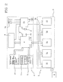
- FIG. 1 an example of a complex installation is noted in which as many as six apparatuses 2 are present for dehumidifying walls, each of which is able to gather data from N fixed humidity sensors 200 that are distributed suitably in a wall area of particular interest.
- the apparatus 2 positioned furthest to the left gathers data, not only from the sensors 200 assigned thereto, but also from all the other dehumidifying apparatuses 2, slave 1, slave 2, all of which are controlled by N sensors 200 assigned thereto.
- the slave apparatus 2 gathers the data from a third and a fourth dehumidifying apparatus 2 (slave 3 and slave 4).
- the latter gather data from some sensors 200 assigned thereto and the apparatus 2 known as a slave 4 also gathers data from the dehumidifying apparatus 2 known as a slave 5.
- the master apparatus 2 will have gathered the data from all the fixed sensors 200, which data will be passed on to the master apparatus 2 by the slave apparatuses 2 that are cascade-connected.
- each slave apparatus 2 must be installed within the range of action of the apparatus 2 to which it is slaved.
- each apparatus 200 for detecting wall humidity has to be installed within the range of action of the dehumidifying apparatus 2 to which it is slaved.
- the apparatuses 2 will be connected to the mains supply and be earthed; the sensors 200 can be installed in the most suitable positions (provided that they are not immersed in water) and be supplied by battery to provide durability of at least 3 years.
- the apparatus 2 for dehumidifying walls will be provided with suitable selecting means 10 for setting the apparatus 2 as the master apparatus, or as the slave apparatus.
- the master apparatus 2 communicates with one or more slave apparatuses 2 directly slaved thereto (for example, in figure 1 the master apparatus communicates with the slave apparatuses 1 and 2).
- each slave apparatus 2 can possibly communicate with one or more further slave apparatuses 2 that are directly slaved thereto.
- the slave apparatus 2 has no further slaved apparatus 2 whereas the slave apparatus 2 has the further slave apparatuses slaves 2, 3 and 4 slaved thereto.
- the system comprises a plurality of apparatuses 200 for detecting humidity, each comprising first selectors 63 for setting an assignment to a specific apparatus 2 for dehumidifying walls.
- the apparatuses 200 communicate directly with the dehumidifying apparatus 2 to which they are slaved.
- the apparatuses 200 also comprise second selectors 64 that define, inside an assignment group 80 of apparatuses 200 assigned to a single apparatus 2, an order of assignment.
- the selecting means 10 of the dehumidifying apparatus 2 for dehumidifying walls enables a physical address to be assigned to the dehumidifying apparatus.
- the "zero" address indicates that the unit is the master.
- the master unit is the only unit that, through the remote communication module 5, dialogues with the remote supervision unit 6.
- One or more first-level slave units can be connected to the master unit.
- One or more second-level slave units can be connected to each first-level slave unit and, one or more N+1 level slave units can be connected to each N level slave unit.
- the radio traffic of each unit is asynchronous in relation to the other units; before starting communication with the sensors or units of a higher level, the unit will wait for the radio channel to be free.
- Each apparatus 2 is managed by a microcontroller 4, which, preferably by using wireless technology to conduct periodical scanning of the remote devices, records in an internal memory 7 the humidity data detected by the single remote sensors 200 together with the ambient humidity and temperature values.
- All the data that are thus recorded can be viewed and scanned locally through the use of the display/keypad applied to the body of the apparatus 2, or also be sent to a portable computer occasionally connected thereto, or transmitted via a telephone connection to a data gathering centre.
Landscapes
- Engineering & Computer Science (AREA)
- Physics & Mathematics (AREA)
- Architecture (AREA)
- Electrochemistry (AREA)
- General Physics & Mathematics (AREA)
- General Engineering & Computer Science (AREA)
- Chemical & Material Sciences (AREA)
- Chemical Kinetics & Catalysis (AREA)
- Automation & Control Theory (AREA)
- Water Supply & Treatment (AREA)
- Mechanical Engineering (AREA)
- Electromagnetism (AREA)
- Civil Engineering (AREA)
- Structural Engineering (AREA)
- Testing Or Calibration Of Command Recording Devices (AREA)
- Investigating Or Analyzing Materials By The Use Of Electric Means (AREA)
- Building Environments (AREA)
Claims (5)
- System zum Entfeuchten von Wänden, das mindestens eine Vorrichtung (2) zum Entfeuchten von Wänden umfasst, einschließend:- wandentfeuchtende Mittel (3), die wirken, um die Entfeuchtung von mindestens einem Wandabschnitt zu fördern, und- mindestens eine Steuereinheit (4), die auf die wandentfeuchtenden Mittel (3) einwirkt, um eine Überwachung des Betriebs zu ermöglichen,wobei die Vorrichtung (2) ferner mindestens ein Kommunikationsmodul (5) umfasst, das mindestens zum Empfang von Anweisungen von einer entfernten Einheit (6) geeignet ist, wobei die Anweisungen an die Steuereinheit (4) gesendet werden, um die Betriebsmodi der Vorrichtung (2) zur Wandentfeuchtung zu ändern, wobei das System dadurch gekennzeichnet ist, dass die Vorrichtung (2) ferner einen Speicher (7) umfasst, enthaltend zumindest ein Entfeuchtungsprofil, wobei die Steuereinheit (4) auf die wandentfeuchtenden Mittel (3) einwirkt, um die wandentfeuchtenden Mittel (3) in Abhängigkeit vom eingestellten Entfeuchtungsprofil zu überwachen,
wobei die Steuereinheit (4) auf den Speicher (7) einwirkt, um das eingestellte Entfeuchtungsprofil in Abhängigkeit von den Anweisungen zu ändern, die von der entfernten Einheit (6) empfangen werden,
wobei das Kommunikationsmodul (5) ferner dazu geeignet ist, Informationen an die entfernte Einheit (6) bezüglich des Betriebs der Vorrichtung (2) zu übertragen,
wobei das System ferner mindestens einen Feuchtigkeitssensor (200) umfasst, der mit der Steuereinheit (4) wirkverbunden ist, um die erfassten Parameter zu übertragen, wobei die erfassten Parameter von der Steuereinheit (4) zum Vergleich mit dem eingestellten Entfeuchtungsprofil und zur Änderung des Betriebs der Vorrichtung (2) in Abhängigkeit der Unterschiede verwendet werden. - System nach Anspruch 1, dadurch gekennzeichnet, dass die Steuereinheit (4) auf die wandentfeuchtenden Mittel (3) einwirkt, um ihre Betriebsparameter in Abhängigkeit von den empfangenen Anweisungen zu variieren, die von der entfernten Einheit (6) kommen.
- System nach einem der vorangehenden Ansprüche, dadurch gekennzeichnet, dass das Kommunikationsmodul (5) bei der Anfrage der entfernten Einheit (6) oder automatisch überträgt, wenn eingestellte Ereignisse auftreten, wie das Überschreiten von Alarmschwellen.
- System nach einem der vorangehenden Ansprüche, dadurch gekennzeichnet, dass die Vorrichtung (2) ferner mindestens eine Pufferbatterie (8) umfasst, die zumindest zur Versorgung der entfeuchtenden Mittel (3) geeignet ist, um im Falle der Abwesenheit einer externen Versorgung eine Betriebsunabhängigkeit zu ermöglichen.
- System nach einem der vorangehenden Ansprüche, wobei die Vorrichtung (2) ferner mindestens ein Solarpaneel (9) umfasst, das zumindest zur Versorgung der entfeuchtenden Mittel (3) geeignet ist.
Priority Applications (2)
| Application Number | Priority Date | Filing Date | Title |
|---|---|---|---|
| EP12183814.8A EP2538207B1 (de) | 2008-08-19 | 2009-08-06 | Tragbares elektronisches Gerät zum ermitteln der Feuchtigkeit von Wänden |
| EP12183815A EP2535782A1 (de) | 2008-08-19 | 2009-08-06 | System zum Entfeuchten von Wänden |
Applications Claiming Priority (1)
| Application Number | Priority Date | Filing Date | Title |
|---|---|---|---|
| ITMI2008A001522A IT1391107B1 (it) | 2008-08-19 | 2008-08-19 | Sistema per il controllo e/o la deumidificazione muraria |
Related Child Applications (2)
| Application Number | Title | Priority Date | Filing Date |
|---|---|---|---|
| EP12183814.8A Division EP2538207B1 (de) | 2008-08-19 | 2009-08-06 | Tragbares elektronisches Gerät zum ermitteln der Feuchtigkeit von Wänden |
| EP12183814.8A Previously-Filed-Application EP2538207B1 (de) | 2008-08-19 | 2009-08-06 | Tragbares elektronisches Gerät zum ermitteln der Feuchtigkeit von Wänden |
Publications (2)
| Publication Number | Publication Date |
|---|---|
| EP2157491A1 EP2157491A1 (de) | 2010-02-24 |
| EP2157491B1 true EP2157491B1 (de) | 2012-10-10 |
Family
ID=40848291
Family Applications (3)
| Application Number | Title | Priority Date | Filing Date |
|---|---|---|---|
| EP12183815A Withdrawn EP2535782A1 (de) | 2008-08-19 | 2009-08-06 | System zum Entfeuchten von Wänden |
| EP12183814.8A Active EP2538207B1 (de) | 2008-08-19 | 2009-08-06 | Tragbares elektronisches Gerät zum ermitteln der Feuchtigkeit von Wänden |
| EP20090167412 Revoked EP2157491B1 (de) | 2008-08-19 | 2009-08-06 | System zum Entfeuchten von Wänden |
Family Applications Before (2)
| Application Number | Title | Priority Date | Filing Date |
|---|---|---|---|
| EP12183815A Withdrawn EP2535782A1 (de) | 2008-08-19 | 2009-08-06 | System zum Entfeuchten von Wänden |
| EP12183814.8A Active EP2538207B1 (de) | 2008-08-19 | 2009-08-06 | Tragbares elektronisches Gerät zum ermitteln der Feuchtigkeit von Wänden |
Country Status (2)
| Country | Link |
|---|---|
| EP (3) | EP2535782A1 (de) |
| IT (1) | IT1391107B1 (de) |
Families Citing this family (10)
| Publication number | Priority date | Publication date | Assignee | Title |
|---|---|---|---|---|
| ITEN20130004A1 (it) * | 2013-10-09 | 2015-04-10 | Skm S R L Soluzioni Kalibrate Per Murature | Dispositivo di deumidificazione muraria |
| ES2750577T3 (es) | 2014-10-08 | 2020-03-26 | Tecnova Group S R L | Sistema de deshumidificación de paredes |
| US10909607B2 (en) | 2015-06-05 | 2021-02-02 | Boveda Inc. | Systems, methods and devices for controlling humidity in a closed environment with automatic and predictive identification, purchase and replacement of optimal humidity controller |
| US10055781B2 (en) | 2015-06-05 | 2018-08-21 | Boveda Inc. | Systems, methods and devices for controlling humidity in a closed environment with automatic and predictive identification, purchase and replacement of optimal humidity controller |
| IT201800004349A1 (it) * | 2018-04-10 | 2019-10-10 | Sistema e metodo per l’individuazione della presenza di acqua liquida in strutture sandwich. | |
| RU185550U1 (ru) * | 2018-10-03 | 2018-12-11 | Общество с ограниченной ответственностью Фирма "Лепта" | Датчик поточного влагомера сыпучих материалов |
| CN112034776A (zh) * | 2020-07-24 | 2020-12-04 | 沈阳国建精材科技发展有限公司 | 无线除湿智能系统 |
| IT202100005570A1 (it) | 2021-03-10 | 2022-09-10 | Leonardo Solutions S R L | Apparecchiatura per neutralizzare la risalita capillare di umidita’ in una muratura in modo controllato |
| PL444181A1 (pl) * | 2023-03-23 | 2023-11-20 | Tabiś Krzysztof Aquapol Polska Cpv | Sonda pomiarowa oraz układ do pomiaru parametrów konstrukcyjnych, zwłaszcza ścian obiektów budowlanych |
| CN119002576B (zh) * | 2024-10-25 | 2024-12-20 | 珠海安德宝科技有限公司 | 一种智能防潮箱湿度调控方法及系统 |
Family Cites Families (7)
| Publication number | Priority date | Publication date | Assignee | Title |
|---|---|---|---|---|
| JPS60135753A (ja) * | 1983-12-23 | 1985-07-19 | Koa Sangyo Kk | 非接触水分検知装置 |
| BE900172A (fr) * | 1984-07-17 | 1984-11-16 | Rynhart Res Ltd | Appareil en vue d'effectuer des mesures de capacite ou d'humidite. |
| ES2161931T3 (es) * | 1995-03-10 | 2001-12-16 | Hildegard Berger | Dispositivo para la deshumectacion de mamposteria. |
| DE19800597A1 (de) * | 1998-01-09 | 1999-07-22 | Hildegard Berger | Vorrichtung zur Entfeuchtung und/oder Entsalzung von Bauwerken |
| US7173538B2 (en) * | 2004-06-25 | 2007-02-06 | Rm2, Inc. | Apparatus, system and method for monitoring a drying procedure |
| ES2310750T3 (es) * | 2004-07-08 | 2009-01-16 | Bernard Stumpp | Dispositivo y procedimiento para detener los ascensos de agua y humedad por capilaridad. |
| US7243050B2 (en) * | 2005-03-05 | 2007-07-10 | Armstrong Jay T | Devices and systems for remote and automated monitoring and control of water removal, mold remediation, and similar work |
-
2008
- 2008-08-19 IT ITMI2008A001522A patent/IT1391107B1/it active
-
2009
- 2009-08-06 EP EP12183815A patent/EP2535782A1/de not_active Withdrawn
- 2009-08-06 EP EP12183814.8A patent/EP2538207B1/de active Active
- 2009-08-06 EP EP20090167412 patent/EP2157491B1/de not_active Revoked
Also Published As
| Publication number | Publication date |
|---|---|
| EP2535782A1 (de) | 2012-12-19 |
| IT1391107B1 (it) | 2011-11-18 |
| ITMI20081522A1 (it) | 2010-02-20 |
| EP2538207A1 (de) | 2012-12-26 |
| EP2157491A1 (de) | 2010-02-24 |
| EP2538207B1 (de) | 2014-05-14 |
Similar Documents
| Publication | Publication Date | Title |
|---|---|---|
| EP2157491B1 (de) | System zum Entfeuchten von Wänden | |
| US20120205455A1 (en) | System for monitoring and/or dehumidifying walls | |
| CA2823053C (en) | Grain bin capacitive moisture sensor system | |
| KR101262882B1 (ko) | 배터리 관리 시스템 내의 데이터 전송을 위한 배터리 관리 시스템 및 방법 | |
| CA2821610C (en) | Grain bin capacitive moisture sensor system and method | |
| KR100719064B1 (ko) | 다중 주파수 용량성 측정 장치 및 그 동작 방법 | |
| CN106461591B (zh) | 测量装置、尤其湿度测量装置 | |
| CN103528763A (zh) | 一种垃圾填埋场渗漏探测方法及探测装置 | |
| CN112881818B (zh) | 电场强度测量方法、装置、计算机设备和存储介质 | |
| CN116015429B (zh) | 光缆探测数据的访问方法、装置、设备及存储介质 | |
| US8924171B2 (en) | Device for monitoring the structure of a vehicle | |
| CN105241503B (zh) | 一种湿度全面检测系统 | |
| CN210513216U (zh) | 监测仪及地源热泵系统 | |
| KR101402862B1 (ko) | 재료 감별 장치 | |
| CN105157747B (zh) | 一种各部件分离的检测系统及检测方法 | |
| US20190360907A1 (en) | Multimodal system for estimating the volume and density of a body | |
| CN116380984A (zh) | 一种考古现场土壤理化参数原位在线监测装置及方法 | |
| ITMI20081521A1 (it) | Apparecchiatura per il rilievo dell'umidita' | |
| JP2006304523A (ja) | 配電設備の管理システムおよび配電設備の管理方法 | |
| CN107300457B (zh) | 用于测量人工降雨均匀度的实验装置 | |
| RU2459954C2 (ru) | Система и способ мониторинга температур протяженных объектов | |
| CN109239011B (zh) | 一种光纤露点湿度检测装置、系统及其控制方法 | |
| CN112394093A (zh) | 一种基于bp神经网络的畜禽粒状饲料水分测量装置 | |
| CN105022066A (zh) | 手持式双探头测量仪 | |
| US12480916B2 (en) | Device monitoring systems and methods |
Legal Events
| Date | Code | Title | Description |
|---|---|---|---|
| PUAI | Public reference made under article 153(3) epc to a published international application that has entered the european phase |
Free format text: ORIGINAL CODE: 0009012 |
|
| AK | Designated contracting states |
Kind code of ref document: A1 Designated state(s): AT BE BG CH CY CZ DE DK EE ES FI FR GB GR HR HU IE IS IT LI LT LU LV MC MK MT NL NO PL PT RO SE SI SK SM TR |
|
| AX | Request for extension of the european patent |
Extension state: AL BA RS |
|
| 17P | Request for examination filed |
Effective date: 20100811 |
|
| 17Q | First examination report despatched |
Effective date: 20100907 |
|
| GRAP | Despatch of communication of intention to grant a patent |
Free format text: ORIGINAL CODE: EPIDOSNIGR1 |
|
| RTI1 | Title (correction) |
Free format text: SYSTEM FOR DEHUMIDIFYING WALLS |
|
| GRAS | Grant fee paid |
Free format text: ORIGINAL CODE: EPIDOSNIGR3 |
|
| GRAA | (expected) grant |
Free format text: ORIGINAL CODE: 0009210 |
|
| AK | Designated contracting states |
Kind code of ref document: B1 Designated state(s): AT BE BG CH CY CZ DE DK EE ES FI FR GB GR HR HU IE IS IT LI LT LU LV MC MK MT NL NO PL PT RO SE SI SK SM TR |
|
| REG | Reference to a national code |
Ref country code: GB Ref legal event code: FG4D |
|
| REG | Reference to a national code |
Ref country code: CH Ref legal event code: EP Ref country code: AT Ref legal event code: REF Ref document number: 579226 Country of ref document: AT Kind code of ref document: T Effective date: 20121015 |
|
| REG | Reference to a national code |
Ref country code: IE Ref legal event code: FG4D |
|
| REG | Reference to a national code |
Ref country code: DE Ref legal event code: R096 Ref document number: 602009010299 Country of ref document: DE Effective date: 20121206 |
|
| REG | Reference to a national code |
Ref country code: CH Ref legal event code: NV Representative=s name: BUGNION S.A., CH |
|
| REG | Reference to a national code |
Ref country code: CH Ref legal event code: NV Representative=s name: BUGNION S.A., CH |
|
| PG25 | Lapsed in a contracting state [announced via postgrant information from national office to epo] |
Ref country code: SI Free format text: LAPSE BECAUSE OF FAILURE TO SUBMIT A TRANSLATION OF THE DESCRIPTION OR TO PAY THE FEE WITHIN THE PRESCRIBED TIME-LIMIT Effective date: 20121010 |
|
| REG | Reference to a national code |
Ref country code: NL Ref legal event code: VDEP Effective date: 20121010 |
|
| REG | Reference to a national code |
Ref country code: AT Ref legal event code: MK05 Ref document number: 579226 Country of ref document: AT Kind code of ref document: T Effective date: 20121010 |
|
| REG | Reference to a national code |
Ref country code: LT Ref legal event code: MG4D |
|
| PG25 | Lapsed in a contracting state [announced via postgrant information from national office to epo] |
Ref country code: LT Free format text: LAPSE BECAUSE OF FAILURE TO SUBMIT A TRANSLATION OF THE DESCRIPTION OR TO PAY THE FEE WITHIN THE PRESCRIBED TIME-LIMIT Effective date: 20121010 Ref country code: IS Free format text: LAPSE BECAUSE OF FAILURE TO SUBMIT A TRANSLATION OF THE DESCRIPTION OR TO PAY THE FEE WITHIN THE PRESCRIBED TIME-LIMIT Effective date: 20130210 Ref country code: NL Free format text: LAPSE BECAUSE OF FAILURE TO SUBMIT A TRANSLATION OF THE DESCRIPTION OR TO PAY THE FEE WITHIN THE PRESCRIBED TIME-LIMIT Effective date: 20121010 Ref country code: NO Free format text: LAPSE BECAUSE OF FAILURE TO SUBMIT A TRANSLATION OF THE DESCRIPTION OR TO PAY THE FEE WITHIN THE PRESCRIBED TIME-LIMIT Effective date: 20130110 Ref country code: SE Free format text: LAPSE BECAUSE OF FAILURE TO SUBMIT A TRANSLATION OF THE DESCRIPTION OR TO PAY THE FEE WITHIN THE PRESCRIBED TIME-LIMIT Effective date: 20121010 Ref country code: HR Free format text: LAPSE BECAUSE OF FAILURE TO SUBMIT A TRANSLATION OF THE DESCRIPTION OR TO PAY THE FEE WITHIN THE PRESCRIBED TIME-LIMIT Effective date: 20121010 Ref country code: FI Free format text: LAPSE BECAUSE OF FAILURE TO SUBMIT A TRANSLATION OF THE DESCRIPTION OR TO PAY THE FEE WITHIN THE PRESCRIBED TIME-LIMIT Effective date: 20121010 Ref country code: ES Free format text: LAPSE BECAUSE OF FAILURE TO SUBMIT A TRANSLATION OF THE DESCRIPTION OR TO PAY THE FEE WITHIN THE PRESCRIBED TIME-LIMIT Effective date: 20130121 |
|
| PG25 | Lapsed in a contracting state [announced via postgrant information from national office to epo] |
Ref country code: LV Free format text: LAPSE BECAUSE OF FAILURE TO SUBMIT A TRANSLATION OF THE DESCRIPTION OR TO PAY THE FEE WITHIN THE PRESCRIBED TIME-LIMIT Effective date: 20121010 Ref country code: BE Free format text: LAPSE BECAUSE OF FAILURE TO SUBMIT A TRANSLATION OF THE DESCRIPTION OR TO PAY THE FEE WITHIN THE PRESCRIBED TIME-LIMIT Effective date: 20121010 Ref country code: GR Free format text: LAPSE BECAUSE OF FAILURE TO SUBMIT A TRANSLATION OF THE DESCRIPTION OR TO PAY THE FEE WITHIN THE PRESCRIBED TIME-LIMIT Effective date: 20130111 Ref country code: PT Free format text: LAPSE BECAUSE OF FAILURE TO SUBMIT A TRANSLATION OF THE DESCRIPTION OR TO PAY THE FEE WITHIN THE PRESCRIBED TIME-LIMIT Effective date: 20130211 Ref country code: PL Free format text: LAPSE BECAUSE OF FAILURE TO SUBMIT A TRANSLATION OF THE DESCRIPTION OR TO PAY THE FEE WITHIN THE PRESCRIBED TIME-LIMIT Effective date: 20121010 |
|
| PG25 | Lapsed in a contracting state [announced via postgrant information from national office to epo] |
Ref country code: AT Free format text: LAPSE BECAUSE OF FAILURE TO SUBMIT A TRANSLATION OF THE DESCRIPTION OR TO PAY THE FEE WITHIN THE PRESCRIBED TIME-LIMIT Effective date: 20121010 |
|
| PLBI | Opposition filed |
Free format text: ORIGINAL CODE: 0009260 |
|
| PG25 | Lapsed in a contracting state [announced via postgrant information from national office to epo] |
Ref country code: SK Free format text: LAPSE BECAUSE OF FAILURE TO SUBMIT A TRANSLATION OF THE DESCRIPTION OR TO PAY THE FEE WITHIN THE PRESCRIBED TIME-LIMIT Effective date: 20121010 Ref country code: EE Free format text: LAPSE BECAUSE OF FAILURE TO SUBMIT A TRANSLATION OF THE DESCRIPTION OR TO PAY THE FEE WITHIN THE PRESCRIBED TIME-LIMIT Effective date: 20121010 Ref country code: BG Free format text: LAPSE BECAUSE OF FAILURE TO SUBMIT A TRANSLATION OF THE DESCRIPTION OR TO PAY THE FEE WITHIN THE PRESCRIBED TIME-LIMIT Effective date: 20130110 Ref country code: CZ Free format text: LAPSE BECAUSE OF FAILURE TO SUBMIT A TRANSLATION OF THE DESCRIPTION OR TO PAY THE FEE WITHIN THE PRESCRIBED TIME-LIMIT Effective date: 20121010 Ref country code: DK Free format text: LAPSE BECAUSE OF FAILURE TO SUBMIT A TRANSLATION OF THE DESCRIPTION OR TO PAY THE FEE WITHIN THE PRESCRIBED TIME-LIMIT Effective date: 20121010 |
|
| 26 | Opposition filed |
Opponent name: ECODRY SYSTEME GMBH Effective date: 20130709 |
|
| PLAX | Notice of opposition and request to file observation + time limit sent |
Free format text: ORIGINAL CODE: EPIDOSNOBS2 |
|
| PG25 | Lapsed in a contracting state [announced via postgrant information from national office to epo] |
Ref country code: RO Free format text: LAPSE BECAUSE OF FAILURE TO SUBMIT A TRANSLATION OF THE DESCRIPTION OR TO PAY THE FEE WITHIN THE PRESCRIBED TIME-LIMIT Effective date: 20121010 Ref country code: IT Free format text: LAPSE BECAUSE OF FAILURE TO SUBMIT A TRANSLATION OF THE DESCRIPTION OR TO PAY THE FEE WITHIN THE PRESCRIBED TIME-LIMIT Effective date: 20121010 |
|
| REG | Reference to a national code |
Ref country code: DE Ref legal event code: R026 Ref document number: 602009010299 Country of ref document: DE Effective date: 20130709 |
|
| PG25 | Lapsed in a contracting state [announced via postgrant information from national office to epo] |
Ref country code: CY Free format text: LAPSE BECAUSE OF FAILURE TO SUBMIT A TRANSLATION OF THE DESCRIPTION OR TO PAY THE FEE WITHIN THE PRESCRIBED TIME-LIMIT Effective date: 20121010 |
|
| PLAF | Information modified related to communication of a notice of opposition and request to file observations + time limit |
Free format text: ORIGINAL CODE: EPIDOSCOBS2 |
|
| PLBB | Reply of patent proprietor to notice(s) of opposition received |
Free format text: ORIGINAL CODE: EPIDOSNOBS3 |
|
| PG25 | Lapsed in a contracting state [announced via postgrant information from national office to epo] |
Ref country code: MC Free format text: LAPSE BECAUSE OF FAILURE TO SUBMIT A TRANSLATION OF THE DESCRIPTION OR TO PAY THE FEE WITHIN THE PRESCRIBED TIME-LIMIT Effective date: 20121010 |
|
| REG | Reference to a national code |
Ref country code: IE Ref legal event code: MM4A |
|
| PG25 | Lapsed in a contracting state [announced via postgrant information from national office to epo] |
Ref country code: IE Free format text: LAPSE BECAUSE OF NON-PAYMENT OF DUE FEES Effective date: 20130806 |
|
| PLCK | Communication despatched that opposition was rejected |
Free format text: ORIGINAL CODE: EPIDOSNREJ1 |
|
| PG25 | Lapsed in a contracting state [announced via postgrant information from national office to epo] |
Ref country code: SM Free format text: LAPSE BECAUSE OF FAILURE TO SUBMIT A TRANSLATION OF THE DESCRIPTION OR TO PAY THE FEE WITHIN THE PRESCRIBED TIME-LIMIT Effective date: 20121010 |
|
| PG25 | Lapsed in a contracting state [announced via postgrant information from national office to epo] |
Ref country code: TR Free format text: LAPSE BECAUSE OF FAILURE TO SUBMIT A TRANSLATION OF THE DESCRIPTION OR TO PAY THE FEE WITHIN THE PRESCRIBED TIME-LIMIT Effective date: 20121010 Ref country code: MT Free format text: LAPSE BECAUSE OF FAILURE TO SUBMIT A TRANSLATION OF THE DESCRIPTION OR TO PAY THE FEE WITHIN THE PRESCRIBED TIME-LIMIT Effective date: 20121010 |
|
| APBM | Appeal reference recorded |
Free format text: ORIGINAL CODE: EPIDOSNREFNO |
|
| APBP | Date of receipt of notice of appeal recorded |
Free format text: ORIGINAL CODE: EPIDOSNNOA2O |
|
| APAH | Appeal reference modified |
Free format text: ORIGINAL CODE: EPIDOSCREFNO |
|
| PG25 | Lapsed in a contracting state [announced via postgrant information from national office to epo] |
Ref country code: MK Free format text: LAPSE BECAUSE OF FAILURE TO SUBMIT A TRANSLATION OF THE DESCRIPTION OR TO PAY THE FEE WITHIN THE PRESCRIBED TIME-LIMIT Effective date: 20121010 Ref country code: HU Free format text: LAPSE BECAUSE OF FAILURE TO SUBMIT A TRANSLATION OF THE DESCRIPTION OR TO PAY THE FEE WITHIN THE PRESCRIBED TIME-LIMIT; INVALID AB INITIO Effective date: 20090806 Ref country code: LU Free format text: LAPSE BECAUSE OF NON-PAYMENT OF DUE FEES Effective date: 20130806 |
|
| APBQ | Date of receipt of statement of grounds of appeal recorded |
Free format text: ORIGINAL CODE: EPIDOSNNOA3O |
|
| REG | Reference to a national code |
Ref country code: FR Ref legal event code: PLFP Year of fee payment: 8 |
|
| PGFP | Annual fee paid to national office [announced via postgrant information from national office to epo] |
Ref country code: GB Payment date: 20160830 Year of fee payment: 8 |
|
| PGFP | Annual fee paid to national office [announced via postgrant information from national office to epo] |
Ref country code: FR Payment date: 20160825 Year of fee payment: 8 |
|
| GBPC | Gb: european patent ceased through non-payment of renewal fee |
Effective date: 20170806 |
|
| REG | Reference to a national code |
Ref country code: FR Ref legal event code: ST Effective date: 20180430 |
|
| PG25 | Lapsed in a contracting state [announced via postgrant information from national office to epo] |
Ref country code: GB Free format text: LAPSE BECAUSE OF NON-PAYMENT OF DUE FEES Effective date: 20170806 |
|
| PG25 | Lapsed in a contracting state [announced via postgrant information from national office to epo] |
Ref country code: FR Free format text: LAPSE BECAUSE OF NON-PAYMENT OF DUE FEES Effective date: 20170831 |
|
| PLAB | Opposition data, opponent's data or that of the opponent's representative modified |
Free format text: ORIGINAL CODE: 0009299OPPO |
|
| APBU | Appeal procedure closed |
Free format text: ORIGINAL CODE: EPIDOSNNOA9O |
|
| R26 | Opposition filed (corrected) |
Opponent name: ECODRY SYSTEME GMBH Effective date: 20130709 |
|
| PGFP | Annual fee paid to national office [announced via postgrant information from national office to epo] |
Ref country code: DE Payment date: 20200903 Year of fee payment: 12 |
|
| PLAB | Opposition data, opponent's data or that of the opponent's representative modified |
Free format text: ORIGINAL CODE: 0009299OPPO |
|
| REG | Reference to a national code |
Ref country code: DE Ref legal event code: R103 Ref document number: 602009010299 Country of ref document: DE Ref country code: DE Ref legal event code: R064 Ref document number: 602009010299 Country of ref document: DE |
|
| PLAB | Opposition data, opponent's data or that of the opponent's representative modified |
Free format text: ORIGINAL CODE: 0009299OPPO |
|
| R26 | Opposition filed (corrected) |
Opponent name: ECODRY SYSTEME GMBH Effective date: 20130709 |
|
| R26 | Opposition filed (corrected) |
Opponent name: ECODRY SYSTEME GMBH Effective date: 20130709 |
|
| RDAF | Communication despatched that patent is revoked |
Free format text: ORIGINAL CODE: EPIDOSNREV1 |
|
| STAA | Information on the status of an ep patent application or granted ep patent |
Free format text: STATUS: THE PATENT HAS BEEN GRANTED |
|
| APBM | Appeal reference recorded |
Free format text: ORIGINAL CODE: EPIDOSNREFNO |
|
| APBP | Date of receipt of notice of appeal recorded |
Free format text: ORIGINAL CODE: EPIDOSNNOA2O |
|
| APAH | Appeal reference modified |
Free format text: ORIGINAL CODE: EPIDOSCREFNO |
|
| APBQ | Date of receipt of statement of grounds of appeal recorded |
Free format text: ORIGINAL CODE: EPIDOSNNOA3O |
|
| PGFP | Annual fee paid to national office [announced via postgrant information from national office to epo] |
Ref country code: CH Payment date: 20210820 Year of fee payment: 13 |
|
| REG | Reference to a national code |
Ref country code: DE Ref legal event code: R119 Ref document number: 602009010299 Country of ref document: DE |
|
| PG25 | Lapsed in a contracting state [announced via postgrant information from national office to epo] |
Ref country code: DE Free format text: LAPSE BECAUSE OF NON-PAYMENT OF DUE FEES Effective date: 20220301 |
|
| REG | Reference to a national code |
Ref country code: CH Ref legal event code: PL |
|
| PG25 | Lapsed in a contracting state [announced via postgrant information from national office to epo] |
Ref country code: LI Free format text: LAPSE BECAUSE OF NON-PAYMENT OF DUE FEES Effective date: 20220831 Ref country code: CH Free format text: LAPSE BECAUSE OF NON-PAYMENT OF DUE FEES Effective date: 20220831 |
|
| APBU | Appeal procedure closed |
Free format text: ORIGINAL CODE: EPIDOSNNOA9O |
|
| RDAG | Patent revoked |
Free format text: ORIGINAL CODE: 0009271 |
|
| STAA | Information on the status of an ep patent application or granted ep patent |
Free format text: STATUS: PATENT REVOKED |
|
| REG | Reference to a national code |
Ref country code: CH Ref legal event code: PL |
|
| 27W | Patent revoked |
Effective date: 20210323 |