EP2157405B1 - Vorrichtung und Verfahren zur Messung physikalischer Größen - Google Patents
Vorrichtung und Verfahren zur Messung physikalischer Größen Download PDFInfo
- Publication number
- EP2157405B1 EP2157405B1 EP08764634.5A EP08764634A EP2157405B1 EP 2157405 B1 EP2157405 B1 EP 2157405B1 EP 08764634 A EP08764634 A EP 08764634A EP 2157405 B1 EP2157405 B1 EP 2157405B1
- Authority
- EP
- European Patent Office
- Prior art keywords
- reference point
- physical quantity
- vector
- difference vector
- difference
- Prior art date
- Legal status (The legal status is an assumption and is not a legal conclusion. Google has not performed a legal analysis and makes no representation as to the accuracy of the status listed.)
- Active
Links
Images


Classifications
-
- G—PHYSICS
- G01—MEASURING; TESTING
- G01C—MEASURING DISTANCES, LEVELS OR BEARINGS; SURVEYING; NAVIGATION; GYROSCOPIC INSTRUMENTS; PHOTOGRAMMETRY OR VIDEOGRAMMETRY
- G01C17/00—Compasses; Devices for ascertaining true or magnetic north for navigation or surveying purposes
- G01C17/38—Testing, calibrating, or compensating of compasses
-
- G—PHYSICS
- G01—MEASURING; TESTING
- G01C—MEASURING DISTANCES, LEVELS OR BEARINGS; SURVEYING; NAVIGATION; GYROSCOPIC INSTRUMENTS; PHOTOGRAMMETRY OR VIDEOGRAMMETRY
- G01C25/00—Manufacturing, calibrating, cleaning, or repairing instruments or devices referred to in the other groups of this subclass
- G01C25/005—Manufacturing, calibrating, cleaning, or repairing instruments or devices referred to in the other groups of this subclass initial alignment, calibration or starting-up of inertial devices
-
- G—PHYSICS
- G01—MEASURING; TESTING
- G01P—MEASURING LINEAR OR ANGULAR SPEED, ACCELERATION, DECELERATION, OR SHOCK; INDICATING PRESENCE, ABSENCE, OR DIRECTION, OF MOVEMENT
- G01P15/00—Measuring acceleration; Measuring deceleration; Measuring shock, i.e. sudden change of acceleration
- G01P15/18—Measuring acceleration; Measuring deceleration; Measuring shock, i.e. sudden change of acceleration in two or more dimensions
-
- G—PHYSICS
- G01—MEASURING; TESTING
- G01P—MEASURING LINEAR OR ANGULAR SPEED, ACCELERATION, DECELERATION, OR SHOCK; INDICATING PRESENCE, ABSENCE, OR DIRECTION, OF MOVEMENT
- G01P21/00—Testing or calibrating of apparatus or devices covered by the preceding groups
Definitions
- the present invention relates to a physical quantity measuring device and a physical quantity measuring method.
- the invention relates to a physical quantity measuring device and a physical quantity measuring method in which an offset included in the vector physical quantity data group can be estimated from a vector physical quantity data group obtained by a sensor detecting a vector physical quantity.
- An azimuth measuring device (so-called electronic compass) is known as a conventional device that magnetic sensors are arranged along two or three directions, geomagnetism is measured and an azimuth is calculated.
- the azimuth measuring device has become increasingly smaller and is incorporated into a portable device such as a mobile telephone or a PDA (Personal Digital Assistant).
- the azimuth measuring device detects magnetism leaked from the magnetized component with the geomagnetism. Thus, an azimuth is calculated by mistake unless an azimuth is determined after a signal component except geomagnetism is subtracted from a measured signal.
- a stationary signal component except geomagnetism is referred to as an offset.
- patent document 1 A method of estimating an offset of an azimuth measuring device that is suitable for a portable appliance is disclosed in patent document 1.
- the method disclosed in patent document 1 is a technique for estimating the offset of the azimuth measuring device incorporated in the portable appliance automatically and unconsciously by the user in view of the fact that the posture of a mobile device is variously changed depending on the use condition of a user.
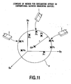
- FIG. 11 is a diagram illustrating the concept of a method of estimating an offset in a conventional azimuth measuring device.
- geomagnetic data obtained by the azimuth measuring device 1 is distributed on the surface of a sphere in which an offset included in the data is located at the center position of the sphere.
- the sensitivities of measurement axes of the azimuth measuring device 1 are considered to be equal to each other.
- an offset a component except geomagnetism included in data is referred to as an offset.
- the center of a spherical surface (when the geomagnetism is detected by using a three-axis geomagnetic sensor) on which a geomagnetic data group is distributed is estimated.
- the center of the spherical surface is referred to as a reference point.
- the reliability of the estimated reference point (whether the reference point is estimated within an estimation error which is allowed by a system) is examined, and thus the reference point is used as the offset of the system on condition that the reference point is determined to be reliable. When the reliability of the reference point is not determined, the reference point is used as the offset of the system.
- N is the number of pieces of geomagnetic data obtained.
- patent document 8 Another method of determining an offset of a sensor is disclosed in patent document 8. According to patent document 8, among three or more points of magnetic data detected by a magnetic detection means, an intersection between a perpendicular bisector to a straight line connecting any two points and a perpendicular bisector to a straight line connecting two points except the above-described two points is determined as an offset.
- any two points are extracted from a plurality of magnetic data many times, a large number of perpendicular bisectors per straight lines connecting two points are set, and the average of coordinates of a plurality of intersections at which the large number of perpendicular bisectors intersect each other is determined as an offset.
- a piezoresistive three-axis acceleration sensor comprised of a semiconductor device employing MEMS (Micro Electro Mechanical Systems) technology has been developed (for example, see patent document 7).
- MEMS Micro Electro Mechanical Systems
- Patent documents 5 and 6 disclose methods for automatically and unconsciously by the user estimating the offset of an acceleration sensor. Any of these methods is a technique based on [Formula 2] and is a technique that estimates the offset with high reliability by utilizing characteristic of acceleration.
- gravitational acceleration measurement data detected by the three-axis acceleration sensor is distributed on the surface of a sphere in which the offset of the acceleration sensor is located at the center position of the sphere.
- the sensitivities of measurement axes of the acceleration sensor are considered to be equal to each other.
- the acceleration sensor detects gravitational acceleration and motion acceleration simultaneously, the separation of the gravitational acceleration and the motion acceleration is a technical point for determining an offset with high reliability.
- the probability that motion acceleration included in the acceleration measurement data is calculated by using variations in acceleration measurement data that is continuous in time.
- an offset can also be estimated from measurement data including motion acceleration.
- Forma 2 is a formula for estimating an offset included in the geomagnetic data group by using a geomagnetic data group obtained in a space in which the magnitude of the geomagnetism is uniform.
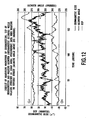
- FIG. 12 is a diagram showing a result of measuring the magnitude of the geomagnetism, the dip of the geomagnetism and a walking azimuth (a geomagnetic azimuth) while walking straight in an urban area.
- the unit of the horizontal axis is considered to be approximately m (meter). It is found that the geomagnetism varies depending on the location. A magnetic substance such as iron included in a building draws the geomagnetism, and thus the geomagnetism is not generally uniform around an artificial building.
- patent document 1 For example, the difference between the maximum value and the minimum value of each axial component of a measurement data group that is used for estimation with [Formula 2] is calculated, and the estimated reference point is used as the offset if the difference is equal to or more than a predetermined value. Even when a data group is obtained at a location where the magnitude of the geomagnetism is different, the accuracy of the estimated reference point can be improved on condition that the data group is distributed over a wide region.
- the difference (i.e. variation) between the maximum value and the minimum value of each axial component of a reference point group that is periodically estimated is calculated, and the estimated reference point is used as the offset when the difference is not more than a predetermined value.
- the measurement data group used for estimation is highly likely to be obtained under a uniform geomagnetism circumstance.
- the measurement data group used for estimation is applied to a plane, the distance between the plane and the measurement data group is calculated.
- the estimated reference point is used as the offset when the maximum value of the distance is equal to or more than a predetermined value.
- Patent document 2 discloses a method in which the predetermined value is periodically set tight (for example, every time an offset is obtained a predetermined number of times), or the predetermined value is set loose when a specific event occurs (for example, every time a magnetic substance component such as a memory card is attached on a portable terminal).
- the reliability is low immediately after a portable device is operated but an offset is estimated rapidly and then the reliability of the offset is gradually improved.
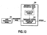
- FIG. 13 is a block diagram showing the configuration of a reference point estimation means 300 of prior art.
- the reference point estimation means 300 stores data obtained by a data acquisition means 301 as required.
- a reference point estimation portion 302 estimates a reference point included in data output from the data acquisition means 301 based on a predetermined evaluation formula 303 by using the stored data group, and outputs the reference point as an offset.
- the reliability of the estimated reference point is checked (Patent documents 1, 2 and 3), and only the reference point that is determined to be reliable is output as the offset.
- any of the above-described conventional methods is a method for improving the probability that an accurate reference point is employed as an offset, and may erroneously use an inaccurate reference point depending on data used for estimation. It takes long time until the offset is obtained, when the predetermined value is set tight such that the inaccurate reference point is not used by mistake.
- the measurement data excluding motion acceleration can be obtained by determining whether a motion of a portable device is stationary. For example, if a variation in each measurement axe of acceleration measurement data group obtained during a predetermined period T is not more than a predetermined range TH, the portable device can be determined to be stationary. When the period T is longer and the range TH is smaller, the probability that motion acceleration included in the measurement data is decreased, but it takes long time until stationary data is obtained (therefore, it takes a long time to obtain the offset). When the period T and the range TH are set loose such that time is shortened until an offset is estimated, the obtained stationary data may include motion acceleration.
- an elevator accelerates or decelerates at a constant acceleration of about 0.1 G ( ⁇ 1 m/s 2 ).
- a vibration during an upward or downward movement is eliminated.
- a stationary acceleration sensor within an elevator receives a constant acceleration of about 1.1 G or 0.9 G, and it often satisfies a stationary judgment criterion mentioned above.
- an object of the present invention is to provide a vector physical quantity measuring device that can estimate a highly reliable offset even if a measurement data group is not obtained in a space in which the magnitude of a vector physical quantity to be measured is uniform.
- the reference point estimation means comprises: a difference vector calculating portion for calculating the difference vector group using a difference between each components of the obtained vector physical quantity data group; and a reference point estimation portion for estimating coordinates of the preference point that is determined coordinate system consisted by the components of the obtained vector physical quantity data group based on the evaluation formula using the calculated difference vector group to output the coordinates of the estimated reference point as an offset.
- the reference point estimation means further comprises: a difference vector reliability calculating portion for determining whether each difference vector of the calculated difference vector group is suited for estimation of the reference point, and outputting only a suitable difference vector group for estimation of the reference point based on a result of the determination.
- the reference point estimation means further comprises: a reliability calculating portion for determining the degree of reliability of the estimated reference point by the difference vector group, and outputting only a suitable reference point as an offset based on a result of the determination.
- the evaluation formula contains an N-th power of a distance between a middle point of the difference vector and a point as a foot of a perpendicular line drawn from the reference point to the difference vector.
- the N is two.
- the reference point estimation means estimates the reference point by using difference vectors that a time difference of obtainment between the obtained two vector physical quantity data is not more than a predetermined value.
- the reference point estimation means calculates a magnitude of the difference vector and estimates the reference point by using the difference vectors whose magnitude are not less than a predetermined value.
- the reference point estimation means calculates an angle formed between a difference vector calculated from two vector physical quantity data including vector physical quantity data that is newly obtained by the data acquisition means and a difference vector calculated from two vector physical quantity data that is obtained before the newly obtained vector physical quantity data by the data acquisition means, and estimates the reference point with the inclusion of a difference vector calculated from the newly obtained vector physical quantity data if the formed angle is not less than a predetermined value.
- the reference point estimation means calculates an angle formed between a difference vector and a vector connecting the middle point of the difference vector with the reference point estimated by the reference point estimation means for each of the difference vector groups used for the estimation of the coordinates of the reference point, and outputs the reference point as an offset if a maximum value of a difference between the formed angle and 90 degrees is not more than a predetermined value.
- the reference point estimation means calculates a distance between a foot of a perpendicular line drawn from the estimated reference point to the difference vector and the middle point of the difference vector for each of the difference vector groups used for the estimation of the coordinates of the reference point, and outputs the reference point as an offset if a maximum value of the calculated distance is not more than a predetermined value.
- the vector physical quantity detection means detects two-component vector physical quantity
- the reference point estimation means calculates a distance between a perpendicular bisector of the difference vector and the estimated reference point, and outputs the reference point for each of the difference vector groups used for the estimation of the coordinates of the reference point as an offset if a maximum value of the calculated distance is not more than a predetermined value.
- the vector physical quantity detection means detects three-component vector physical quantity detection means, and the reference point estimation means calculates a distance between a perpendicular bisector plane of the difference vector and the estimated reference point for each of the difference vector groups used for the estimation of the coordinates of the reference point, and outputs the reference point as an offset if a maximum value of the calculated distance is not more than a predetermined value.
- the vector physical quantity detection means is a magnetic sensor that detects magnetism as the physical quantity.
- the vector physical quantity detection means is an acceleration sensor that detects acceleration as the physical quantity.
- a vector physical quantity composed of a plurality of components is repeatedly detected and is obtained as vector physical quantity data, and thus a vector physical quantity data group is obtained.
- a difference vector group is calculated from the obtained vector physical quantity data group.
- a reference point included in the obtained vector physical quantity data group is estimated based on a predetermined evaluation formula using the calculated difference vector group. Therefore, it is possible to estimate an offset with high reliability even if the measurement data group is not a measurement data group that is obtained in a space in which the magnitude of a vector physical quantity as a measurement object is uniform.
- each difference vector of the calculated difference vector group is suitable for the estimation of the reference point. Only a suitable difference vector group is used for the estimation of the reference point based on the determination result. Degree of reliability of the estimated reference point is judged by using the difference vector group. Only a reliable reference point is output as an offset based on the judged result. Therefore, it is possible to further improve the reliability of the estimated offset.
- FIG. 1 schematically shows the overall configuration of a physical quantity measuring system 100.
- the physical quantity measuring system 100 includes a physical quantity measuring device 10 and a calculating portion 200.
- the physical quantity measuring device 10 includes a vector physical quantity detection means 20, a data acquisition means 30 and a reference point estimation means 40.
- the vector physical quantity detection means 20 detects a vector physical quantity composed of a plurality of components.
- the data acquisition means 30 repeatedly obtains the detected vector physical quantity as vector physical quantity data to make up a vector physical quantity data group.
- the reference point estimation means 40 calculates a difference vector group from the acquired vector physical quantity data group, estimates, based on a predetermined evaluation formula using the calculated difference vector group, a reference point included in the vector physical quantity data group to output the estimated reference point as an offset.
- the calculating portion 200 calculates information necessary for the system based on the vector physical quantity data group obtained by the physical quantity measuring device 10 and the estimated offset.
- FIG. 2 shows a configuration example of the reference point estimation means 40.
- the reference point estimation means 40 includes a difference vector calculation portion 41 and a reference point estimation portion 42.
- the difference vector calculating portion 41 calculates a difference vector group (V1) from differences between the components of the obtained vector physical quantity data group.
- the reference point estimation portion 42 Based on an evaluation formula 43 using the calculated difference vector group (V1) and a vector physical quantity data group (D1) that is used for calculating the difference vector, the reference point estimation portion 42 statistically estimates the coordinates of a reference point on a coordinate system where each component of vector physical quantity data group constitute coordinate value, and outputs the coordinates of the estimated reference point as an offset.
- the vector physical quantity detection means 20 detects a physical quantity composed of two components or three components, and outputs a signal corresponding to the detected physical quantity.
- the physical quantity as a measurement object for example, includes the geomagnetism and acceleration.
- the vector physical quantity detection means 20 for example, a magnetic sensor that detects magnetism and outputs a voltage proportional to the detected magnetism, an acceleration sensor that detects acceleration and outputs a voltage proportional to the detected acceleration or the like can be used.
- the data acquisition means 30 converts the signal output by the vector physical quantity detection means 20 into an output signal that is easily processed by latter blocks (the blocks after the reference point estimation means 40).
- the data acquisition means 30, for example, amplifies a signal output by the vector physical quantity detection means 20, converts the amplified signal to a digital signal by A/D conversion form, and outputs the converted digital signal as a digital data. Further, a filtering process may be performed for eliminating noise at the same time of the amplifying process.
- the signal is amplified and filtered to improve S/N (Signal to Noise), and then converted into digital data for easy processing by a computer or the like, to be output.
- the detected signal may be processed as the analog signal without A/D conversion, and latter processing may be performed by using the analog signal.
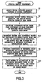
- FIG. 3 is a flowchart showing an outline of the measurement of a physical quantity in the physical quantity measuring device 10.
- step S1 the vector physical quantity comprised of a plurality of components is detected.
- step S2 the vector physical quantity is repeatedly detected, and thus the vector physical quantity data group is obtained.
- step S3 a difference of each component of the obtained vector physical quantity data group is calculated, and thus the difference vector group is obtained.
- step S4 based on the evaluation formula 43 that uses the difference vector group, a coordinate of the reference point set on a coordinate system constituted of each component of the obtained vector physical quantity data group is statistically estimated.
- the coordinate of the estimated reference point are output as an offset.
- the difference vector is calculated from two of the measurement data obtained by the data acquisition means 30 or two data calculated from the measurement data group. Then, as required, the difference vector and data comprised of the difference vector are stored. A reference point of measurement data group obtained by the data acquisition means 30 is estimated based on a predetermined evaluation formula by the stored difference vector group and the data group comprised of the difference vector. Thus, the estimated reference point is output as an offset.
- Two data comprised of the difference vector may be configured by data that obtained by the data acquisition means 30, or may be configured by values that obtained by performing a calculation (for example, averaging)on the measurement data group so as to reduce an effect of noise.
- the calculating portion 200 receives the measurement data obtained from the data acquisition means 30 and the offset estimated by the reference point estimation means 40 of the physical quantity measuring device 10. Thus, information necessary for the system is calculated.
- the physical quantity detection means is a three-axis magnetic sensor and an azimuth measuring device detects the geomagnetism to calculate an azimuth. Using the estimated offset and the obtained measurement data, the value of the geomagnetism is calculated, and the azimuth is calculated.
- the estimated offset is set to as (o x , o y , o z ).
- the azimuth of x-measurement axis to the magnetic north is calculated by the following formula.
- ⁇ tan - 1 ⁇ - m y - o y m x - o x .
- the physical quantity detection means 20 is a three-axis acceleration sensor and an inclination angle measuring device calculates the inclination to the horizontal plane of the portable device.
- the value of the gravitational acceleration is calculated from the estimated offset and the obtained data. Then, the inclination angle of the portable device is calculated.
- the angle ⁇ of the x-measurement axis and the angle ⁇ of the y-measurement axis to the horizontal plane respectively are calculated by the following formulas.
- the geomagnetic measurement data is distributed on a spherical surface.
- the geomagnetic data is distributed on a circle (so-called, an azimuth circle) in which an offset is centered at the circle.
- a two-dimensional case will be primarily described below.
- a three-dimensional case will be described in the same theory as the two-dimensional case.
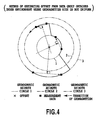
- FIG. 4 is a diagram illustrating a method of estimating an offset by using a data group obtained from the circumstance that the size of geomagnetism is not uniform.
- FIG. 4 shows a variation of time to the magnetism detected by a two-axis magnetic sensor fixed horizontally on the dashboard of an automobile.
- a bridge is often an iron-based structure, and a large amount of the geomagnetism is induced into such structure. Then, the magnitude and direction of geomagnetism are varied.
- An iron-based structure may be buried under a road. In the case of a road in a city, the geomagnetism is also affected by buildings around the road.
- measurement values of the geomagnetism detected by the magnetic sensor mounted within the automobile are not distributed on only one circle, but are distributed on a plurality of circles located concentrically. Therefore, the accuracy of an offset calculated by [Formula 2] (a formula acquired by correcting [Formula 2] in terms of two components) is not of high precision.
- FIG. 4 is a diagram for the concept of the present invention, and shows magnetic data obtained when the automobile moves under three regions that the magnitude of the geomagnetism is different.
- the perpendicular bisectors of two geomagnetic data obtained in a region of the same magnitude of the geomagnetism pass through the offset.
- the offset can be estimated from the perpendicular bisectors.
- Actual geomagnetic measurement data often includes noise, and it is not necessarily possible to obtain two geomagnetic data in the region that the magnitude of the geomagnetism is the same value.
- the inner product between the difference vector comprised of two geomagnetic data on one azimuth circle and a vector connecting the offset of the geomagnetic sensor with the middle point of the difference vector is zero.
- the magnitude of the geomagnetism varies when a location is a little changed.
- it is difficult to obtain two measurement data on the same azimuth circle but it may be considered that two data obtained in close locations (that is, close in time) exist on the same azimuth circle substantially.
- Even when the magnitude of the azimuth circle varies with time if a pair of pieces of measurement data on the azimuth circle of the same (substantially the same) magnitude can be obtained, the inner products determined from each pair of measurement data are all close to zero.
- the square of the absolute value of the inner product determined from all pairs of the measurement data is represented by the following formula.
- the value of "S" is zero. Actually, since the measurement value may include noise and may be a pair of measurement data that does not exactly exist on the same azimuth circle, the value of "S” is approximately zero.
- a method of estimating "o” so as to minimize [Formula 6] is appropriate as the estimation method.
- the method of minimizing [Formula 6] there is a method of using iteration such as a Newton-Raphson method to determine "o” asymptotically. Further, it is possible to analytically determine "o” value by solving the following simultaneous equation.
- Formula 8 the square of the distance between the middle point of a difference vector comprised of two measurement data and a point as a foot of a perpendicular drawn from the reference point to the difference vector is calculated for each difference vector.
- Formula 8 represents that the sum of value of the square of the distance calculated per each difference vector.
- Formula 9 represents that the sum of values of the square of the distance calculated per each difference vector.
- the square of the distance between the perpendicular bisector plane of a difference vector comprised of two measurement data and the reference point is calculated per each difference vector, and thus the sum of values of the square of the distance calculated for each difference vector.
- the description of [Formula 9] of the three-component physical quantity detection device is the same as that of the two-component physical quantity detection device because [Formula 9] is represented by using a vector description.
- [Formula 6], [Formula 8] and [Formula 9] are formed such that the sum of the squares of the absolute values, they may be generally formed such that the sum of the N-th powers of the absolute values is determined.
- the evaluation formula [Formula 6] instead of the evaluation formula [Formula 6], the following formula may be used.
- the perpendicular bisector of two difference vectors passes through the reference point when the physical quantity detection means detects a two-component physical quantity (In the case of a three-component physical quantity, the perpendicular bisector plane of three difference vectors is used)
- the physical quantity detection means detects a two-component physical quantity
- some pairs of two difference vectors are made, and the intersection of the perpendicular bisector is calculated per each pair.
- the N-th power of the sum of the distance between the intersection calculated per the each pair and the reference point may be determined as an evaluation formula ([Formula 11]).
- a T represents a horizontal vector.
- a method for determining a specific point from a plurality of difference vectors (For example, "A" difference vectors) is defined. Some sets of "A" difference vectors are made, the specific point is calculated per each sets. Thus, a formula for determining the N-th power of the sum of the distances between the specific points calculated per the each sets and the reference point may be determined as an evaluation formula.
- FIGS. 5 to 8 The second embodiment of the present invention will be described based on FIGS. 5 to 8 .
- the same parts as those of the above-described first example are identified with like reference numerals, and their description will be omitted.
- FIG. 5 shows another configuration example of the reference point estimation means 40 shown in FIG. 2 .
- the reference point estimation means 40 further comprises a difference vector reliability calculating portion 50.
- step S10 the difference vector reliability calculating portion 50 determines whether each difference vector of the calculated difference vector group is suitable for the estimation of the reference point, and outputs only a suitable difference vector group for the estimation of the reference point based on the determination result.
- the accuracy of estimating an offset may be not high precision depending on how two data constituting the difference vector are selected.
- the following reasons are described. Even if the difference vector is calculated from any two data obtained by the data acquisition means 30 of FIG. 1 and the "o" is determined so as to minimize the evaluation formulas [Formula 6], [Formula 8] and [Formula 9], generally measurement data includes noise and two data constituting the difference vector are not necessarily located on one azimuth circle. For this reason, it is preferred that only the difference vector suitable for the estimation of the reference point is selected and the reference point is estimated.
- the difference vector reliability calculating portion 50 determines, with one or a plurality of methods, whether each difference vector of the difference vector group output from the difference vector calculating portion 41 is suitable for the estimation of the reference point.
- the difference vector reliability calculating portion 50 outputs, to the reference point estimation portion 42, a difference vector group V2 that is comprised of only difference vectors determined to be suitable for the estimation of the reference point and a data group D2 that constitutes the difference vector group (a group of pieces of vector physical quantity data used for calculation of each difference vector).
- FIGS. 6A and 6B are diagrams that show a relationship among the difference vector utilized for estimation of the reference point, noise included in the measurement data 401 and the offset 400.
- FIG. 6A shows an example that the magnitude of the difference vector is large.
- FIG. 6B shows an example that the difference vector is small.
- FIGS. 6A and 6B show a relationship between the perpendicular bisector of the difference vector and the center of the azimuth circle when noise is included in one datum of one pair of data.
- the obtained times of the two magnetic data for calculating the difference vector should be determined to be a predetermined value or less.
- FIGS. 8A and 8B are diagrams showing a relationship between an intersection between two perpendicular bisectors set by the geomagnetic data including noise and a true offset.
- the magnetic data includes noise, a large amount of errors are included depending on the perpendicular bisector used for the estimation of an offset.
- FIG. 14 is a diagram illustrating the concept of a case where an offset is estimated by use of [Formula 7] and the method disclosed in document 8.
- a true offset of the geomagnetic sensor is represented by "X", and an azimuth circle drawn according to measurement values of the geomagnetic sensor is represented by a dotted line.
- the reference numeral 410 represents an offset estimated by [Formula 7] from 12 points of magnetic data.
- the reference numeral 510 represents an offset estimated from document 8.
- the offset 410 estimated by [Formula 7] is determined from all 12 points of magnetic data at a time.
- the offset 510 is estimated as the following steps. First, an intersection of two bisectors is determined from four points that are respectively represented by measurement data 401, measurement data 420 and measurement data 430. Next, three intersections that are finally determined are averaged. Noise not more than 10% of a radius of the azimuth circle is included in all magnetic data.
- the offset 410 determined from [Formula 7] of the present invention is not equal to the offset 510 determined by the method disclosed in document 8.
- noises superimposed on the difference vector are cancelled each other due to a random characteristic. Even if the noise is superimposed on the difference vector, an offset value close to a true value can be calculated.
- a perpendicular bisector connecting two points that are located a relatively short distance apart is used. Further, the intersection is determined by two perpendicular bisectors that are relatively close to each other and the determined intersection is averaged. In this case, noises included in the two perpendicular bisectors that are relatively close to each other are not always cancelled each other, and noises included in the offset value are increased. Thus, the offset value may be greatly different from the true value.
- noises are not cancelled each other. The error between the true value and the determined offset is probably increased.
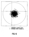
- FIG. 15 is a diagram showing all the offsets that are estimated by performing an offset estimation with [Formula 7] of the present invention 1000 times.
- FIG. 16 is a diagram showing all the offsets that are estimated by performing an offset estimation with the method of document 8 1000 times.
- FIGS. 7A and 7B are diagrams that show a relationship between the difference vector utilized for estimation of the reference point, a time difference in the obtainment of measurement data 401 comprising the difference vector and the offset 400.
- FIG. 7A shows an example of a case where the time difference is small.
- FIG. 7B shows an example of a case where the time difference is large.
- FIGS. 7A and 7B show that the perpendicular bisector of a difference vector calculated from the measurement data 401 that is not located on the same azimuth circle may be located far away from a point showing the offset 400 even if the magnitude of the difference vector is large.
- the reference numeral 402 represents geomagnetic transition.
- FIGS. 8A and 8B are diagrams showing a relationship an angle formed among the difference vectors utilized for estimation of the reference point and the offset 400 when noise is included in the measurement data 401
- FIG. 8A shows an example of a case where the angle formed between the difference vectors is small.
- FIG. 8B shows an example of a case where the angle formed between the difference vectors is large.
- FIGS. 8A and 8B show, when noise is included in the measurement data 401, a relationship between an angle formed among the difference vectors utilized for estimation of the reference point and the offset 400.
- An estimated reference point an intersection between two difference vectors
- An estimated reference point may be located far away from a true offset when an angle formed between two difference vectors (substantially parallel to each other) is small.
- the difference vector reliability calculation means on the basis of a difference vector that is previously determined to be reliable by the difference vector reliability calculation means, when an angle formed between the difference vector and a newly calculated difference vector is not less than a predetermined angle, the newly calculated difference vector is used for the estimation of the reference point as a reliable difference vector. On the other hand, when the angle formed is not more than the predetermined angle, the newly calculated difference vector is determined to be unreliable and then is discarded. In this way, it is possible to avoid the estimation of the reference point by only using difference vectors indicating in the same direction.
- FIGS. 9 to 10B The third embodiment of the present invention will be described based on FIGS. 9 to 10B .
- the same parts as those of the above-described examples are identified with like symbols, and their description will be omitted.
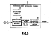
- FIG. 9 shows a configuration example of the reference point estimation portion 42 shown in FIG. 5 .
- the reference point estimation portion 42 includes an estimation portion 51 and a reliability calculating portion 52.
- the estimation portion 51 estimates the reference point included in the vector physical quantity data group based on the evaluation formula 43 using the calculated difference vector group.
- the reliability calculating portion 52 determines the degree of reliability of the estimated reference point with the difference vector group, and outputs only a reliable reference point as an offset based on the determination result.
- the function of the reliability calculating portion 52 will be specifically described below.
- the measurement data includes noise and the magnitude of the geomagnetism varies.
- the estimated reference point generally includes an error. It is necessary to check the degree of reliability of the estimated reference point.
- the estimated reference point is outputted as an offset only if it is determined to be reliable.
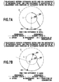
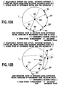
- FIGS. 10A and 10B are diagrams showing a relationship between the true offset 400, the estimated reference point 403 and a vector drawn from the estimated reference point 403 to the middle point of the difference vector used for the estimation.
- FIG. 10A shows an example of a case where the reference point is estimated by using difference vectors comprised of the measurement data 401 with no noise.
- FIG. 10B shows an example of a case where the reference point is estimated by using difference vectors comprised of the measurement data 401 including noise.
- each difference vector used for the estimation when each difference vector used for the estimation is obtained under a circumstance that the magnitude of vector physical quantity is the same value and each difference vector is comprised of the measurement data 401 with no noise, the estimated reference point is consistent with the true offset 400, and the vector connecting the middle point of each difference vector with the reference point is perpendicular to each difference vector.
- each difference vector used for the estimation is obtained under a circumstance that the magnitude of vector physical quantity is different value or each difference vector is comprised of data including noise, the estimated reference point 403 is not consistent with the true offset, and an angle formed between each difference vector and the vector connecting the middle point of each difference vector with the reference point is 90 degrees or less.
- an angle formed between the difference vector and the vector connecting the estimated reference point with the middle point of the difference vector is calculated. If the differences between all the calculated formed angles and the angle of 90 degrees are not more than a predetermined value, the estimated reference point is determined to be reliable. On the other hand, at least one of the differences between the formed angles and the angle of 90 degrees is not less than the predetermined value, the estimated reference point is determined to be unreliable and is then discarded. In this way, it is possible to estimate an offset with further improved reliability.
- the geomagnetism, the acceleration or the like is taken as a familiar example of a vector physical quantity to be measured in the present invention. Any other physical quantity such as artificial stationary magnetic field or electric field may be used when variation of the magnitude of a vector physical quantity is slower relative to variation of the relative positional relationship between the vector physical quantity and a vector physical quantity detection means.
Landscapes
- Physics & Mathematics (AREA)
- General Physics & Mathematics (AREA)
- Engineering & Computer Science (AREA)
- Radar, Positioning & Navigation (AREA)
- Remote Sensing (AREA)
- Manufacturing & Machinery (AREA)
- Measuring Magnetic Variables (AREA)
- Indication And Recording Devices For Special Purposes And Tariff Metering Devices (AREA)
- Length Measuring Devices With Unspecified Measuring Means (AREA)
- Testing Or Calibration Of Command Recording Devices (AREA)
Claims (28)
- Vorrichtung zum Messen einer physikalischen Größe (10) aufweisend:ein Mittel (20) zum Erfassen einer physikalischen Vektorgröße, das zum Erfassen einer physikalischen Vektorgröße ausgebildet ist, die aus mehreren Komponenten besteht;ein Datengewinnungsmittel (30), das zum wiederholten Erhalten der erfassten physikalischen Vektorgröße als physikalisches Vektorgrößendaten ausgebildet ist, um eine physikalische Vektorgrößendatengruppe zu erhalten; undein Referenzpunktschätzmittel (40), das zum Berechnen einer Differenzvektorgruppe aus der erhaltenen physikalischen Vektorgrößendatengruppe und zum Schätzen eines Referenzpunktes, der in der erhaltenen physikalischen Vektorgrößendatengruppe enthalten ist, auf Grundlage einer vorbestimmten Auswertungsformel unter Verwendung der berechneten Differenzvektorgruppe, ausgebildet ist;wobei die Auswertungsformel dadurch gekennzeichnet ist, dass die Auswertungsformel unter Verwendung einer N-ten Potenz einer Distanz zwischen einem Mittelpunkt des Differenzvektors und einem Punkt als einen Fuß einer senkrechten Linie, die vom Referenzpunkt zum Differenzvektor gezogen wird, bestimmt wird.
- Vorrichtung (10) zum Messen einer physikalischen Größe nach Anspruch 1,
wobei das Referenzpunktschätzmittel (40) aufweist:einen Differenzvektorberechnungsabschnitt (41), der zum Berechnen der Differenzvektorgruppe unter Verwendung einer Differenz zwischen jeder Komponente der erhaltenen physikalischen Vektorgrößendatengruppe ausgebildet ist; undeinen Referenzpunktschätzabschnitt (42), der zum Schätzen, auf Grundlage der Auswertungsformel unter Verwendung der berechneten Differenzvektorgruppe, von Koordinaten des Referenzpunktes, der auf einem Koordinatensystem bestimmt wird, das durch die Komponenten der erhaltenen physikalischen Vektorgrößendatengruppe gebildet wird, ausgebildet ist, um die Koordinaten des geschätzten Referenzpunktes als Versatz auszugeben. - Vorrichtung (10) zum Messen einer physikalischen Größe nach Anspruch 1 oder 2,
wobei das Referenzpunktschätzmittel (40) des Weiteren aufweist:einen Differenzvektor-Zuverlässigkeitsberechnungsabschnitt (50), der zum Bestimmen ausgebildet ist, ob jeder Differenzvektor der berechneten Differenzvektorgruppe für eine Schätzung des Referenzpunktes geeignet ist, und nur eine geeignete Differenzvektorgruppe zur Schätzung des Referenzpunktes auf Grundlage eines Ergebnisses der Bestimmung ausgibt. - Vorrichtung (10) zum Messen einer physikalischen Größe nach einem der Ansprüche 1 bis 3,
wobei das Referenzpunktschätzmittel (40) des Weiteren aufweist:einen Zuverlässigkeitsberechnungsabschnitt (52), der zum Bestimmen des Zuverlässigkeitsgrades des geschätzten Referenzpunktes durch die Differenzvektorgruppe und zum Ausgeben nur eines geeigneten Referenzpunktes als Versatz auf Grundlage eines Ergebnisses der Bestimmung ausgebildet ist. - Vorrichtung (10) zum Messen einer physikalischen Größe nach Ansprüchen 1 bis 4, wobei das N zwei ist.
- Vorrichtung (10) zum Messen einer physikalischen Größe nach einem der Ansprüche 1 bis 5,
wobei das Referenzpunktschätzmittel (40) zum Schätzen des Referenzpunktes unter Verwendung von Differenzvektoren ausgebildet ist, so dass eine Zeitdifferenz des Erhaltens zwischen den erhaltenen zwei physikalischen Vektorgrößendaten nicht mehr als ein vorbestimmter Wert ist. - Vorrichtung (10) zum Messen einer physikalischen Größe nach einem der Ansprüche 1 bis 6,
wobei das Referenzpunktschätzmittel (40) zum Berechnen einer Größe des Differenzvektors und zum Schätzen des Referenzpunktes unter Verwendung der Differenzvektoren ausgebildet ist, deren Größe nicht kleiner als ein vorbestimmter Wert ist. - Vorrichtung (10) zum Messen einer physikalischen Größe nach einem der Ansprüche 1 bis 7,
wobei das Referenzpunktschätzmittel (40) zum Berechnen eines Winkels ausgebildet ist, der zwischen einem Differenzvektor, der aus zwei physikalischen Vektorgrößendaten berechnet wird, einschließlich physikalischer Vektorgrößendaten, die von dem Datengewinnungsmittel neu erhalten werden, und einem Differenzvektor, der aus zwei physikalischen Vektorgrößendaten berechnet wird, die vor den neu erhaltenen physikalischen Vektorgrößendaten von dem Datengewinnungsmittel erhalten werden, gebildet wird, sowie zum Schätzen des Referenzpunktes unter Einschluss eines Differenzvektors, der aus den neu erhaltenen physikalischen Vektorgrößendaten berechnet wird, wenn der gebildete Winkel nicht kleiner als ein vorbestimmter Wert ist. - Vorrichtung (10) zum Messen einer physikalischen Größe nach einem der Ansprüche 1 bis 8,
wobei das Referenzpunktschätzmittel (40) zum Berechnen eines Winkels ausgebildet ist, der zwischen einem Differenzvektor und einem Vektor gebildet ist, der den Mittelpunkt des Differenzvektors mit dem Referenzpunkt verbindet, der von dem Referenzpunktschätzmittel für jede der Differenzvektorgruppen geschätzt wird, die zum Schätzen der Koordinaten des Referenzpunkts verwendet werden, sowie zum Ausgeben des Referenzpunktes als einen Versatz, wenn ein Maximalwert einer Differenz zwischen dem gebildeten Winkel und 90 Grad nicht mehr als ein vorbestimmter Wert ist. - Vorrichtung (10) zum Messen einer physikalischen Größe nach einem der Ansprüche 1 bis 9,
wobei das Referenzpunktschätzmittel (40) zum Berechnen einer Distanz zwischen einem Fuß einer senkrechten Linie, die vom geschätzten Referenzpunkt zum Differenzvektor gezogen wird, und dem Mittelpunkt des Differenzvektors für jede der Differenzvektorgruppen, die zum Schätzen der Koordinaten des Referenzpunktes verwendet werden, ausgebildet ist, sowie zum Ausgeben des Referenzpunktes als einen Versatz, wenn ein Maximalwert der berechneten Distanz nicht mehr als ein vorbestimmter Wert ist. - Vorrichtung (10) zum Messen einer physikalischen Größe nach einem der Ansprüche 1 bis 10,
wobei das Mittel (20) zum Erfassen einer physikalischen Vektorgröße zum Erfassen einer physikalischen Zweikomponenten-Vektorgröße ausgebildet ist, und
das Referenzpunktschätzmittel (40) zum Berechnen einer Distanz zwischen einer senkrechten Halbierenden des Differenzvektors und dem geschätzten Referenzpunkt für jede der Differenzvektorgruppen, die zum Schätzen der Koordinaten des Referenzpunktes verwendet werden, ausgebildet ist, sowie zum Ausgeben des Referenzpunktes als einen Versatz, wenn ein Maximalwert der berechneten Distanz nicht mehr als ein vorbestimmter Wert ist. - Vorrichtung (10) zum Messen einer physikalischen Größe nach einem der Ansprüche 1 bis 11,
wobei das Mittel (20) zum Erfassen einer physikalischen Vektorgröße zum Erfassen einer physikalischen Dreikomponenten-Vektorgröße ausgebildet ist, und
das Referenzpunktschätzmittel (40) zum Berechnen einer Distanz zwischen einer senkrechten halbierenden Ebene des Differenzvektors und dem geschätzten Referenzpunkt für jede der Differenzvektorgruppen, die zum Schätzen der Koordinaten des Referenzpunktes verwendet werden, ausgebildet ist, sowie zum Ausgeben des Referenzpunktes als einen Versatz, wenn ein Maximalwert der berechneten Distanz nicht mehr als ein vorbestimmter Wert ist. - Vorrichtung (10) zum Messen einer physikalischen Größe nach einem der Ansprüche 1 bis 12,
wobei das Mittel (20) zum Erfassen einer physikalischen Vektorgröße ein Magnetsensor ist, der einen Magnetismus als die physikalische Größe erfasst. - Vorrichtung (10) zum Messen einer physikalischen Größe nach einem der Ansprüche 1 bis 13,
wobei das Mittel (20) zum Erfassen einer physikalischen Vektorgröße ein Beschleunigungssensor ist, der eine Beschleunigung als die physikalische Größe erfasst. - Verfahren zum Messen einer physikalischen Größe, umfassend die folgenden Schritte:Erfassen einer physikalischen Vektorgröße, die aus mehreren Komponenten besteht;wiederholtes Erhalten der erfassten physikalischen Vektorgröße als physikalische Vektorgrößendaten, um physikalische Vektorgrößendatengruppe zu erhalten; undBerechnen einer Differenzvektorgruppe aus der erhaltenen physikalischen Vektorgrößendatengruppe und Schätzen eines Referenzpunktes, der in der erhaltenen physikalischen Vektorgrößendatengruppe enthalten ist, auf Grundlage einer vorbestimmten Auswertungsformel unter Verwendung der berechneten Differenzvektorgruppe;wobei die Auswertungsformel dadurch gekennzeichnet ist, dass die Auswertungsformel unter Verwendung einer N-ten Potenz einer Distanz zwischen einem Mittelpunkt des Differenzvektors und einem Punkt als einen Fuß einer senkrechten Linie, die vom Referenzpunkt zum Differenzvektor gezogen wird, bestimmt wird.
- Verfahren zum Messen einer physikalischen Größe nach Anspruch 15,
wobei der Schritt zum Schätzen des Referenzpunktes die folgenden Schritte umfasst:Berechnen der Differenzvektorgruppe unter Verwendung einer Differenz zwischen jeder Komponente der erhaltenen physikalischen Vektorgrößendatengruppe; undSchätzen, auf Grundlage der Auswertungsformel unter Verwendung der berechneten Differenzvektorgruppe, von Koordinaten des Referenzpunktes, der auf einem vorbestimmten Koordinatensystem bestimmt wird, das durch die Komponenten der erhaltenen physikalischen Vektorgrößendatengruppe gebildet wird, um die Koordinaten des geschätzten Referenzpunktes als Versatz auszugeben. - Verfahren zum Messen einer physikalischen Größe nach Anspruch 15 oder 16,
wobei der Schritt zum Schätzen des Referenzpunktes des Weiteren den folgenden Schritt umfasst:Bestimmen, ob jeder Differenzvektor der berechneten Differenzvektorgruppe für eine Schätzung des Referenzpunktes geeignet ist, und Ausgeben nur einer geeigneten Differenzvektorgruppe zur Schätzung des Referenzpunktes auf Grundlage eines Ergebnisses der Bestimmung. - Verfahren zum Messen einer physikalischen Größe nach einem der Ansprüche 15 bis 17,
wobei der Schritt zum Schätzen des Referenzpunktes des Weiteren den folgenden Schritt umfasst:Bestimmen des Zuverlässigkeitsgrades des geschätzten Referenzpunktes durch die Differenzvektorgruppe und Ausgeben nur eines geeigneten Referenzpunktes als Versatz auf Grundlage eines Ergebnisses der Bestimmung. - Verfahren zum Messen einer physikalischen Größe nach einem der Ansprüche 15 bis 18,
wobei das N zwei ist. - Verfahren zum Messen einer physikalischen Größe nach einem der Ansprüche 15 bis 19,
wobei der Schritt zum Schätzen des Referenzpunktes den Referenzpunkt unter Verwendung von Differenzvektoren schützt, so dass eine Zeitdifferenz des Erhaltens zwischen den erhaltenen zwei physikalischen Vektorgrößendaten, die aus dem Differenzvektor bestehen, nicht mehr als ein vorbestimmter Wert ist. - Verfahren zum Messen einer physikalischen Größe nach einem der Ansprüche 15 bis 20,
wobei der Schritt zum Schätzen des Referenzpunktes eine Größe des Differenzvektors berechnet und den Referenzpunkt unter Verwendung der Differenzvektoren schätzt, deren Größe nicht kleiner als ein vorbestimmter Wert ist. - Verfahren zum Messen einer physikalischen Größe nach einem der Ansprüche 15 bis 21,
wobei der Schritt zum Schätzen des Referenzpunktes einen Winkel berechnet, der zwischen einem Differenzvektor, der aus zwei physikalischen Vektorgrößendaten berechnet wird, einschließlich physikalischer Vektorgrößendaten, die im Datengewinnungsschritt neu erhalten werden, und einem Differenzvektor, der aus zwei physikalischen Vektorgrößendaten berechnet wird, die vor den neu erhaltenen physikalischen Vektorgrößendaten im Datengewinnungsschritt erhalten werden, gebildet wird, und den Referenzpunkt unter Einschluss eines Differenzvektors, der aus den neu erhaltenen physikalischen Vektorgrößendaten berechnet wird, schätzt, wenn der gebildete Winkel nicht kleiner als ein vorbestimmter Wert ist. - Verfahren zum Messen einer physikalischen Größe nach einem der Ansprüche 15 bis 22,
wobei der Schritt zum Schätzen des Referenzpunktes einen Winkel berechnet, der zwischen einem Differenzvektor und einem Vektor gebildet ist, der den Mittelpunkt des Differenzvektors mit dem Referenzpunkt verbindet, der im Referenzpunktschätzschritt für jede der Differenzvektorgruppen geschätzt wird, die zum Schätzen der Koordinaten des Referenzpunkts verwendet werden, und den Referenzpunkt als einen Versatz ausgibt, wenn ein Maximalwert einer Differenz zwischen dem gebildeten Winkel und 90 Grad nicht mehr als ein vorbestimmter Wert ist. - Verfahren zum Messen einer physikalischen Größe nach einem der Ansprüche 15 bis 23,
wobei der Schritt zum Schätzen des Referenzpunktes eine Distanz zwischen einem Fuß einer senkrechten Linie, die vom geschätzten Referenzpunkt zum Differenzvektor gezogen wird, und dem Mittelpunkt des Differenzvektors für jede der Differenzvektorgruppen, die zum Schätzen der Koordinaten des Referenzpunktes verwendet werden, berechnet und den Referenzpunkt als einen Versatz ausgibt, wenn ein Maximalwert der berechneten Distanz nicht mehr als ein vorbestimmter Wert ist. - Verfahren zum Messen einer physikalischen Größe nach einem der Ansprüche 15 bis 24,
wobei der Schritt zum Erfassen der physikalischen Vektorgröße ein Schritt zum Erfassen einer physikalischen Zweikomponenten-Vektorgröße ist, und
der Schritt zum Schätzen des Referenzpunkts eine Distanz zwischen einer senkrechten Halbierenden des Differenzvektors und dem geschätzten Referenzpunkt für jede der Differenzvektorgruppen berechnet, die zum Schätzen der Koordinaten des Referenzpunktes verwendet werden, und den Referenzpunkt als einen Versatz ausgibt, wenn ein Maximalwert der berechneten Distanz nicht mehr als ein vorbestimmter Wert ist. - Verfahren zum Messen einer physikalischen Größe nach einem der Ansprüche 15 bis 25,
wobei der Schritt zum Erfassen der physikalischen Vektorgröße ein Schritt zum Erfassen einer physikalischen Dreikomponenten-Vektorgröße ist, und
der Schritt zum Schätzen des Referenzpunkts eine Distanz zwischen einer senkrechten halbierenden Ebene des Differenzvektors und dem geschätzten Referenzpunkt für jede der Differenzvektorgruppen, die zum Schätzen der Koordinaten des Referenzpunktes verwendet werden, berechnet und den Referenzpunkt als einen Versatz ausgibt, wenn ein Maximalwert der berechneten Distanz nicht mehr als ein vorbestimmter Wert ist. - Verfahren zum Messen einer physikalischen Größe nach einem der Ansprüche 15 bis 26,
wobei der Schritt zum Erfassen der physikalischen Vektorgröße einen Schritt zum Erfassen eines Magnetismus als physikalische Größe unter Verwendung eines Magnetsensors aufweist. - Verfahren zum Messen einer physikalischen Größe nach einem der Ansprüche 15 bis 27,
wobei der Schritt zum Erfassen der physikalischen Vektorgröße einen Schritt zum Erfassen einer Beschleunigung als physikalische Größe unter Verwendung eines Beschleunigungssensors aufweist.
Priority Applications (1)
| Application Number | Priority Date | Filing Date | Title |
|---|---|---|---|
| EP12187416.8A EP2543961B1 (de) | 2007-05-24 | 2008-05-23 | Vorrichtung zur Messung der physikalischen Größe und Verfahren zur Messung der physikalischen Größe |
Applications Claiming Priority (2)
| Application Number | Priority Date | Filing Date | Title |
|---|---|---|---|
| JP2007137927 | 2007-05-24 | ||
| PCT/JP2008/059588 WO2008146757A1 (ja) | 2007-05-24 | 2008-05-23 | 物理量計測装置および物理量計測方法 |
Related Child Applications (2)
| Application Number | Title | Priority Date | Filing Date |
|---|---|---|---|
| EP12187416.8A Division EP2543961B1 (de) | 2007-05-24 | 2008-05-23 | Vorrichtung zur Messung der physikalischen Größe und Verfahren zur Messung der physikalischen Größe |
| EP12187416.8 Division-Into | 2012-10-05 |
Publications (3)
| Publication Number | Publication Date |
|---|---|
| EP2157405A1 EP2157405A1 (de) | 2010-02-24 |
| EP2157405A4 EP2157405A4 (de) | 2012-08-22 |
| EP2157405B1 true EP2157405B1 (de) | 2013-07-31 |
Family
ID=40075003
Family Applications (2)
| Application Number | Title | Priority Date | Filing Date |
|---|---|---|---|
| EP08764634.5A Active EP2157405B1 (de) | 2007-05-24 | 2008-05-23 | Vorrichtung und Verfahren zur Messung physikalischer Größen |
| EP12187416.8A Active EP2543961B1 (de) | 2007-05-24 | 2008-05-23 | Vorrichtung zur Messung der physikalischen Größe und Verfahren zur Messung der physikalischen Größe |
Family Applications After (1)
| Application Number | Title | Priority Date | Filing Date |
|---|---|---|---|
| EP12187416.8A Active EP2543961B1 (de) | 2007-05-24 | 2008-05-23 | Vorrichtung zur Messung der physikalischen Größe und Verfahren zur Messung der physikalischen Größe |
Country Status (5)
| Country | Link |
|---|---|
| US (1) | US20100161272A1 (de) |
| EP (2) | EP2157405B1 (de) |
| JP (1) | JP4787359B2 (de) |
| CN (1) | CN101680760A (de) |
| WO (1) | WO2008146757A1 (de) |
Families Citing this family (13)
| Publication number | Priority date | Publication date | Assignee | Title |
|---|---|---|---|---|
| CN101606037B (zh) * | 2007-02-09 | 2011-05-18 | 旭化成微电子株式会社 | 空间信息检测系统及其检测方法以及空间信息检测装置 |
| JP4908637B2 (ja) | 2008-11-20 | 2012-04-04 | 旭化成エレクトロニクス株式会社 | 物理量計測装置および物理量計測方法 |
| CN102510994B (zh) * | 2009-09-26 | 2014-01-08 | 阿尔卑斯电气株式会社 | 地磁检测装置 |
| JP5144701B2 (ja) * | 2010-03-10 | 2013-02-13 | アルプス電気株式会社 | 磁界検知装置 |
| JP2013064695A (ja) * | 2011-09-20 | 2013-04-11 | Yamaha Corp | 状態推定装置、オフセット更新方法およびオフセット更新プログラム |
| FR2992735B1 (fr) * | 2012-06-29 | 2015-07-03 | Movea | Procede de calibration continue d'un capteur |
| FR2998663B1 (fr) * | 2012-11-28 | 2014-11-21 | Sagem Defense Securite | Procede de calibration d'une centrale inertielle a plage de retournement mecanique limitee |
| FI126012B (fi) | 2012-12-31 | 2016-05-31 | Suunto Oy | Menetelmä ja laite suunnan määrittämiseksi magneettikentässä |
| CN104204734B (zh) * | 2013-03-15 | 2017-05-10 | 旭化成微电子株式会社 | 物理量数据校正装置以及物理量数据校正方法 |
| JP6430262B2 (ja) * | 2015-01-16 | 2018-11-28 | ローム株式会社 | オフセット算出装置及びこれを用いた方位角センサ |
| JP2016153746A (ja) * | 2015-02-20 | 2016-08-25 | セイコーエプソン株式会社 | 計測装置、計測方法、および計測システム |
| JP2020020630A (ja) * | 2018-07-31 | 2020-02-06 | セイコーエプソン株式会社 | 姿勢推定方法、姿勢推定装置及び移動体 |
| CN111366324A (zh) * | 2018-12-26 | 2020-07-03 | 明门(中国)幼童用品有限公司 | 电子式冲击测试机 |
Family Cites Families (18)
| Publication number | Priority date | Publication date | Assignee | Title |
|---|---|---|---|---|
| US4497034A (en) * | 1981-08-05 | 1985-01-29 | Nippon Soken, Inc. | Heading detecting apparatus |
| US4807462A (en) * | 1987-04-03 | 1989-02-28 | Chrysler Motors Corporation | Method for performing automatic calibrations in an electronic compass |
| EP0657746A3 (de) * | 1991-09-17 | 1995-11-22 | Siemens Ag | Verfahren zur Kompensation eines magnetischen Störfeldes in einem Fahrzeug. |
| US5297065A (en) * | 1991-12-27 | 1994-03-22 | Chrysler Corporation | Magnetic transient detection and calibration technique for an auto-calibrating compass |
| US5297063A (en) * | 1991-12-27 | 1994-03-22 | Chrysler Corporation | Method for selecting calibration data for an auto-calibrating compass |
| US6301794B1 (en) * | 1999-05-27 | 2001-10-16 | Johnson Controls, Inc. | Vehicle compass system with continuous automatic calibration |
| JP3985215B2 (ja) | 2001-09-26 | 2007-10-03 | 日立金属株式会社 | 半導体加速度センサー |
| KR100939158B1 (ko) * | 2002-07-01 | 2010-01-28 | 아사히 가세이 일렉트로닉스 가부시끼가이샤 | 방위각 계측 장치 및 방위각 계측 방법 |
| EP1643212B1 (de) * | 2003-07-03 | 2011-04-06 | Asahi Kasei EMD Corporation | Azimut-messeinrichtung und azimut-messverfahren |
| CN100573049C (zh) * | 2003-12-22 | 2009-12-23 | 旭化成电子材料元件株式会社 | 方位角计测装置 |
| JP4638670B2 (ja) * | 2003-12-26 | 2011-02-23 | 旭化成エレクトロニクス株式会社 | 方位角計測方法および方位角計測装置 |
| JP2005207799A (ja) * | 2004-01-21 | 2005-08-04 | Nec Tokin Corp | 立体画像表示システム及び立体ナビゲーションシステム |
| WO2006016671A1 (ja) * | 2004-08-12 | 2006-02-16 | Asahi Kasei Emd Corporation | 加速度計測装置 |
| JP2006226810A (ja) | 2005-02-17 | 2006-08-31 | Alps Electric Co Ltd | 方位計測装置 |
| JP2006234581A (ja) * | 2005-02-24 | 2006-09-07 | Aichi Micro Intelligent Corp | 電子コンパス及び方位測定方法 |
| JP2006275524A (ja) * | 2005-03-28 | 2006-10-12 | Citizen Watch Co Ltd | 電子方位計及び記録媒体 |
| EP1970713B1 (de) * | 2006-01-05 | 2013-03-27 | Asahi Kasei EMD Corporation | Beschleunigungsmesseinrichtung |
| JP4899525B2 (ja) * | 2006-02-21 | 2012-03-21 | ヤマハ株式会社 | 磁気センサ制御装置、磁気測定装置、並びにオフセット設定方法及びプログラム |
-
2008
- 2008-05-23 CN CN200880017242A patent/CN101680760A/zh active Pending
- 2008-05-23 EP EP08764634.5A patent/EP2157405B1/de active Active
- 2008-05-23 EP EP12187416.8A patent/EP2543961B1/de active Active
- 2008-05-23 WO PCT/JP2008/059588 patent/WO2008146757A1/ja active Application Filing
- 2008-05-23 JP JP2009516307A patent/JP4787359B2/ja active Active
- 2008-05-23 US US12/601,462 patent/US20100161272A1/en not_active Abandoned
Also Published As
| Publication number | Publication date |
|---|---|
| EP2543961B1 (de) | 2014-12-24 |
| EP2157405A1 (de) | 2010-02-24 |
| JP4787359B2 (ja) | 2011-10-05 |
| EP2157405A4 (de) | 2012-08-22 |
| WO2008146757A1 (ja) | 2008-12-04 |
| CN101680760A (zh) | 2010-03-24 |
| JPWO2008146757A1 (ja) | 2010-08-19 |
| EP2543961A1 (de) | 2013-01-09 |
| US20100161272A1 (en) | 2010-06-24 |
Similar Documents
| Publication | Publication Date | Title |
|---|---|---|
| EP2157405B1 (de) | Vorrichtung und Verfahren zur Messung physikalischer Größen | |
| EP2351981B1 (de) | Vorrichtung zur Messung physikalischer Größen und Verfahren zur Messung physikalischer Größen | |
| US10337884B2 (en) | Method and apparatus for fast magnetometer calibration | |
| JP6257865B2 (ja) | 測位装置および測位方法 | |
| CN100510623C (zh) | 移动终端装置 | |
| CN100504295C (zh) | 移动电子三维罗盘 | |
| US20120278024A1 (en) | Position estimation apparatus and method using acceleration sensor | |
| JPWO2006035505A1 (ja) | 磁気センサの制御方法、制御装置、および携帯端末装置 | |
| JP5706576B2 (ja) | オフセット推定装置、オフセット推定方法、オフセット推定プログラムおよび情報処理装置 | |
| JP4590511B2 (ja) | 電子コンパス | |
| CN102313822A (zh) | 偏置估算方法、姿势估算方法、偏置估算装置及姿势估算装置 | |
| Höflinger et al. | Indoor-localization system using a micro-inertial measurement unit (imu) | |
| US20090204351A1 (en) | Sensor Apparatus | |
| Tao et al. | Precise displacement estimation from time-differenced carrier phase to improve PDR performance | |
| Marotto et al. | Orientation analysis through a gyroscope sensor for indoor navigation systems | |
| WO2011129288A1 (ja) | 地磁気検知装置 | |
| Árvai et al. | Filtering methods for indoor magnetic compass | |
| Kröger et al. | Method of pedestrian dead reckoning using speed recognition | |
| KR20080053281A (ko) | 센서장치 | |
| KR101376598B1 (ko) | 이동체의 움직임 측정장치, 그 측정 및 보정 방법 | |
| Ravani et al. | A comparative experimental evaluation of IMU designs | |
| JP2007163389A (ja) | 方位センサ | |
| Kinnunen | Verification of a vehicle navigation system | |
| Porvatov et al. | Methods for determining mobile location in zones without GPS reception | |
| Chiou et al. | Localization Experiments Based on Inertial Sensors for Navigation Applications |
Legal Events
| Date | Code | Title | Description |
|---|---|---|---|
| PUAI | Public reference made under article 153(3) epc to a published international application that has entered the european phase |
Free format text: ORIGINAL CODE: 0009012 |
|
| 17P | Request for examination filed |
Effective date: 20091124 |
|
| AK | Designated contracting states |
Kind code of ref document: A1 Designated state(s): AT BE BG CH CY CZ DE DK EE ES FI FR GB GR HR HU IE IS IT LI LT LU LV MC MT NL NO PL PT RO SE SI SK TR |
|
| AX | Request for extension of the european patent |
Extension state: AL BA MK RS |
|
| DAX | Request for extension of the european patent (deleted) | ||
| A4 | Supplementary search report drawn up and despatched |
Effective date: 20120725 |
|
| RIC1 | Information provided on ipc code assigned before grant |
Ipc: G01C 17/38 20060101AFI20120719BHEP Ipc: G01P 21/00 20060101ALI20120719BHEP Ipc: G01C 25/00 20060101ALI20120719BHEP Ipc: G01P 15/18 20060101ALI20120719BHEP |
|
| GRAP | Despatch of communication of intention to grant a patent |
Free format text: ORIGINAL CODE: EPIDOSNIGR1 |
|
| GRAS | Grant fee paid |
Free format text: ORIGINAL CODE: EPIDOSNIGR3 |
|
| GRAA | (expected) grant |
Free format text: ORIGINAL CODE: 0009210 |
|
| AK | Designated contracting states |
Kind code of ref document: B1 Designated state(s): AT BE BG CH CY CZ DE DK EE ES FI FR GB GR HR HU IE IS IT LI LT LU LV MC MT NL NO PL PT RO SE SI SK TR |
|
| REG | Reference to a national code |
Ref country code: GB Ref legal event code: FG4D Ref country code: CH Ref legal event code: EP |
|
| REG | Reference to a national code |
Ref country code: AT Ref legal event code: REF Ref document number: 624901 Country of ref document: AT Kind code of ref document: T Effective date: 20130815 |
|
| REG | Reference to a national code |
Ref country code: IE Ref legal event code: FG4D |
|
| REG | Reference to a national code |
Ref country code: DE Ref legal event code: R096 Ref document number: 602008026437 Country of ref document: DE Effective date: 20130926 |
|
| REG | Reference to a national code |
Ref country code: AT Ref legal event code: MK05 Ref document number: 624901 Country of ref document: AT Kind code of ref document: T Effective date: 20130731 |
|
| REG | Reference to a national code |
Ref country code: NL Ref legal event code: VDEP Effective date: 20130731 |
|
| REG | Reference to a national code |
Ref country code: LT Ref legal event code: MG4D |
|
| PG25 | Lapsed in a contracting state [announced via postgrant information from national office to epo] |
Ref country code: CY Free format text: LAPSE BECAUSE OF FAILURE TO SUBMIT A TRANSLATION OF THE DESCRIPTION OR TO PAY THE FEE WITHIN THE PRESCRIBED TIME-LIMIT Effective date: 20130821 Ref country code: IS Free format text: LAPSE BECAUSE OF FAILURE TO SUBMIT A TRANSLATION OF THE DESCRIPTION OR TO PAY THE FEE WITHIN THE PRESCRIBED TIME-LIMIT Effective date: 20131130 Ref country code: LT Free format text: LAPSE BECAUSE OF FAILURE TO SUBMIT A TRANSLATION OF THE DESCRIPTION OR TO PAY THE FEE WITHIN THE PRESCRIBED TIME-LIMIT Effective date: 20130731 Ref country code: PT Free format text: LAPSE BECAUSE OF FAILURE TO SUBMIT A TRANSLATION OF THE DESCRIPTION OR TO PAY THE FEE WITHIN THE PRESCRIBED TIME-LIMIT Effective date: 20131202 Ref country code: BE Free format text: LAPSE BECAUSE OF FAILURE TO SUBMIT A TRANSLATION OF THE DESCRIPTION OR TO PAY THE FEE WITHIN THE PRESCRIBED TIME-LIMIT Effective date: 20130731 Ref country code: SE Free format text: LAPSE BECAUSE OF FAILURE TO SUBMIT A TRANSLATION OF THE DESCRIPTION OR TO PAY THE FEE WITHIN THE PRESCRIBED TIME-LIMIT Effective date: 20130731 Ref country code: HR Free format text: LAPSE BECAUSE OF FAILURE TO SUBMIT A TRANSLATION OF THE DESCRIPTION OR TO PAY THE FEE WITHIN THE PRESCRIBED TIME-LIMIT Effective date: 20130731 Ref country code: AT Free format text: LAPSE BECAUSE OF FAILURE TO SUBMIT A TRANSLATION OF THE DESCRIPTION OR TO PAY THE FEE WITHIN THE PRESCRIBED TIME-LIMIT Effective date: 20130731 Ref country code: NO Free format text: LAPSE BECAUSE OF FAILURE TO SUBMIT A TRANSLATION OF THE DESCRIPTION OR TO PAY THE FEE WITHIN THE PRESCRIBED TIME-LIMIT Effective date: 20131031 |
|
| PG25 | Lapsed in a contracting state [announced via postgrant information from national office to epo] |
Ref country code: GR Free format text: LAPSE BECAUSE OF FAILURE TO SUBMIT A TRANSLATION OF THE DESCRIPTION OR TO PAY THE FEE WITHIN THE PRESCRIBED TIME-LIMIT Effective date: 20131101 Ref country code: SI Free format text: LAPSE BECAUSE OF FAILURE TO SUBMIT A TRANSLATION OF THE DESCRIPTION OR TO PAY THE FEE WITHIN THE PRESCRIBED TIME-LIMIT Effective date: 20130731 Ref country code: FI Free format text: LAPSE BECAUSE OF FAILURE TO SUBMIT A TRANSLATION OF THE DESCRIPTION OR TO PAY THE FEE WITHIN THE PRESCRIBED TIME-LIMIT Effective date: 20130731 Ref country code: PL Free format text: LAPSE BECAUSE OF FAILURE TO SUBMIT A TRANSLATION OF THE DESCRIPTION OR TO PAY THE FEE WITHIN THE PRESCRIBED TIME-LIMIT Effective date: 20130731 Ref country code: LV Free format text: LAPSE BECAUSE OF FAILURE TO SUBMIT A TRANSLATION OF THE DESCRIPTION OR TO PAY THE FEE WITHIN THE PRESCRIBED TIME-LIMIT Effective date: 20130731 Ref country code: NL Free format text: LAPSE BECAUSE OF FAILURE TO SUBMIT A TRANSLATION OF THE DESCRIPTION OR TO PAY THE FEE WITHIN THE PRESCRIBED TIME-LIMIT Effective date: 20130731 |
|
| PG25 | Lapsed in a contracting state [announced via postgrant information from national office to epo] |
Ref country code: CY Free format text: LAPSE BECAUSE OF FAILURE TO SUBMIT A TRANSLATION OF THE DESCRIPTION OR TO PAY THE FEE WITHIN THE PRESCRIBED TIME-LIMIT Effective date: 20130731 |
|
| PG25 | Lapsed in a contracting state [announced via postgrant information from national office to epo] |
Ref country code: RO Free format text: LAPSE BECAUSE OF FAILURE TO SUBMIT A TRANSLATION OF THE DESCRIPTION OR TO PAY THE FEE WITHIN THE PRESCRIBED TIME-LIMIT Effective date: 20130731 Ref country code: CZ Free format text: LAPSE BECAUSE OF FAILURE TO SUBMIT A TRANSLATION OF THE DESCRIPTION OR TO PAY THE FEE WITHIN THE PRESCRIBED TIME-LIMIT Effective date: 20130731 Ref country code: DK Free format text: LAPSE BECAUSE OF FAILURE TO SUBMIT A TRANSLATION OF THE DESCRIPTION OR TO PAY THE FEE WITHIN THE PRESCRIBED TIME-LIMIT Effective date: 20130731 Ref country code: SK Free format text: LAPSE BECAUSE OF FAILURE TO SUBMIT A TRANSLATION OF THE DESCRIPTION OR TO PAY THE FEE WITHIN THE PRESCRIBED TIME-LIMIT Effective date: 20130731 Ref country code: EE Free format text: LAPSE BECAUSE OF FAILURE TO SUBMIT A TRANSLATION OF THE DESCRIPTION OR TO PAY THE FEE WITHIN THE PRESCRIBED TIME-LIMIT Effective date: 20130731 |
|
| PG25 | Lapsed in a contracting state [announced via postgrant information from national office to epo] |
Ref country code: IT Free format text: LAPSE BECAUSE OF FAILURE TO SUBMIT A TRANSLATION OF THE DESCRIPTION OR TO PAY THE FEE WITHIN THE PRESCRIBED TIME-LIMIT Effective date: 20130731 Ref country code: ES Free format text: LAPSE BECAUSE OF FAILURE TO SUBMIT A TRANSLATION OF THE DESCRIPTION OR TO PAY THE FEE WITHIN THE PRESCRIBED TIME-LIMIT Effective date: 20130731 |
|
| PLBE | No opposition filed within time limit |
Free format text: ORIGINAL CODE: 0009261 |
|
| STAA | Information on the status of an ep patent application or granted ep patent |
Free format text: STATUS: NO OPPOSITION FILED WITHIN TIME LIMIT |
|
| 26N | No opposition filed |
Effective date: 20140502 |
|
| REG | Reference to a national code |
Ref country code: DE Ref legal event code: R097 Ref document number: 602008026437 Country of ref document: DE Effective date: 20140502 |
|
| PG25 | Lapsed in a contracting state [announced via postgrant information from national office to epo] |
Ref country code: LU Free format text: LAPSE BECAUSE OF FAILURE TO SUBMIT A TRANSLATION OF THE DESCRIPTION OR TO PAY THE FEE WITHIN THE PRESCRIBED TIME-LIMIT Effective date: 20140523 |
|
| REG | Reference to a national code |
Ref country code: CH Ref legal event code: PL |
|
| PG25 | Lapsed in a contracting state [announced via postgrant information from national office to epo] |
Ref country code: MC Free format text: LAPSE BECAUSE OF FAILURE TO SUBMIT A TRANSLATION OF THE DESCRIPTION OR TO PAY THE FEE WITHIN THE PRESCRIBED TIME-LIMIT Effective date: 20130731 Ref country code: LI Free format text: LAPSE BECAUSE OF NON-PAYMENT OF DUE FEES Effective date: 20140531 Ref country code: CH Free format text: LAPSE BECAUSE OF NON-PAYMENT OF DUE FEES Effective date: 20140531 |
|
| REG | Reference to a national code |
Ref country code: IE Ref legal event code: MM4A |
|
| REG | Reference to a national code |
Ref country code: FR Ref legal event code: ST Effective date: 20150130 |
|
| PG25 | Lapsed in a contracting state [announced via postgrant information from national office to epo] |
Ref country code: IE Free format text: LAPSE BECAUSE OF NON-PAYMENT OF DUE FEES Effective date: 20140523 |
|
| PG25 | Lapsed in a contracting state [announced via postgrant information from national office to epo] |
Ref country code: FR Free format text: LAPSE BECAUSE OF NON-PAYMENT OF DUE FEES Effective date: 20140602 |
|
| PG25 | Lapsed in a contracting state [announced via postgrant information from national office to epo] |
Ref country code: MT Free format text: LAPSE BECAUSE OF FAILURE TO SUBMIT A TRANSLATION OF THE DESCRIPTION OR TO PAY THE FEE WITHIN THE PRESCRIBED TIME-LIMIT Effective date: 20130731 |
|
| PG25 | Lapsed in a contracting state [announced via postgrant information from national office to epo] |
Ref country code: BG Free format text: LAPSE BECAUSE OF FAILURE TO SUBMIT A TRANSLATION OF THE DESCRIPTION OR TO PAY THE FEE WITHIN THE PRESCRIBED TIME-LIMIT Effective date: 20130731 |
|
| PG25 | Lapsed in a contracting state [announced via postgrant information from national office to epo] |
Ref country code: TR Free format text: LAPSE BECAUSE OF FAILURE TO SUBMIT A TRANSLATION OF THE DESCRIPTION OR TO PAY THE FEE WITHIN THE PRESCRIBED TIME-LIMIT Effective date: 20130731 Ref country code: HU Free format text: LAPSE BECAUSE OF FAILURE TO SUBMIT A TRANSLATION OF THE DESCRIPTION OR TO PAY THE FEE WITHIN THE PRESCRIBED TIME-LIMIT; INVALID AB INITIO Effective date: 20080523 |
|
| PGFP | Annual fee paid to national office [announced via postgrant information from national office to epo] |
Ref country code: GB Payment date: 20170517 Year of fee payment: 10 |
|
| GBPC | Gb: european patent ceased through non-payment of renewal fee |
Effective date: 20180523 |
|
| PG25 | Lapsed in a contracting state [announced via postgrant information from national office to epo] |
Ref country code: GB Free format text: LAPSE BECAUSE OF NON-PAYMENT OF DUE FEES Effective date: 20180523 |
|
| P01 | Opt-out of the competence of the unified patent court (upc) registered |
Effective date: 20230515 |
|
| PGFP | Annual fee paid to national office [announced via postgrant information from national office to epo] |
Ref country code: DE Payment date: 20230331 Year of fee payment: 16 |