EP2155482B1 - Verfahren zum aufwickeln und spleissen eines kernprofiles für einen fahrzeugreifen mit einer wickeltrommel - Google Patents
Verfahren zum aufwickeln und spleissen eines kernprofiles für einen fahrzeugreifen mit einer wickeltrommel Download PDFInfo
- Publication number
- EP2155482B1 EP2155482B1 EP08736410A EP08736410A EP2155482B1 EP 2155482 B1 EP2155482 B1 EP 2155482B1 EP 08736410 A EP08736410 A EP 08736410A EP 08736410 A EP08736410 A EP 08736410A EP 2155482 B1 EP2155482 B1 EP 2155482B1
- Authority
- EP
- European Patent Office
- Prior art keywords
- material strip
- winding drum
- winding
- splicing
- strip
- Prior art date
- Legal status (The legal status is an assumption and is not a legal conclusion. Google has not performed a legal analysis and makes no representation as to the accuracy of the status listed.)
- Active
Links
Images


Classifications
-
- B—PERFORMING OPERATIONS; TRANSPORTING
- B29—WORKING OF PLASTICS; WORKING OF SUBSTANCES IN A PLASTIC STATE IN GENERAL
- B29D—PRODUCING PARTICULAR ARTICLES FROM PLASTICS OR FROM SUBSTANCES IN A PLASTIC STATE
- B29D30/00—Producing pneumatic or solid tyres or parts thereof
- B29D30/06—Pneumatic tyres or parts thereof (e.g. produced by casting, moulding, compression moulding, injection moulding, centrifugal casting)
- B29D30/48—Bead-rings or bead-cores; Treatment thereof prior to building the tyre
-
- B—PERFORMING OPERATIONS; TRANSPORTING
- B29—WORKING OF PLASTICS; WORKING OF SUBSTANCES IN A PLASTIC STATE IN GENERAL
- B29D—PRODUCING PARTICULAR ARTICLES FROM PLASTICS OR FROM SUBSTANCES IN A PLASTIC STATE
- B29D30/00—Producing pneumatic or solid tyres or parts thereof
- B29D30/06—Pneumatic tyres or parts thereof (e.g. produced by casting, moulding, compression moulding, injection moulding, centrifugal casting)
- B29D30/38—Textile inserts, e.g. cord or canvas layers, for tyres; Treatment of inserts prior to building the tyre
- B29D30/44—Stretching or treating the layers before application on the drum
- B29D2030/4468—Holding the layers
-
- B—PERFORMING OPERATIONS; TRANSPORTING
- B29—WORKING OF PLASTICS; WORKING OF SUBSTANCES IN A PLASTIC STATE IN GENERAL
- B29D—PRODUCING PARTICULAR ARTICLES FROM PLASTICS OR FROM SUBSTANCES IN A PLASTIC STATE
- B29D30/00—Producing pneumatic or solid tyres or parts thereof
- B29D30/06—Pneumatic tyres or parts thereof (e.g. produced by casting, moulding, compression moulding, injection moulding, centrifugal casting)
- B29D30/38—Textile inserts, e.g. cord or canvas layers, for tyres; Treatment of inserts prior to building the tyre
- B29D30/46—Cutting textile inserts to required shape
- B29D2030/463—Holding the textile inserts during cutting; means therefor
-
- B—PERFORMING OPERATIONS; TRANSPORTING
- B29—WORKING OF PLASTICS; WORKING OF SUBSTANCES IN A PLASTIC STATE IN GENERAL
- B29D—PRODUCING PARTICULAR ARTICLES FROM PLASTICS OR FROM SUBSTANCES IN A PLASTIC STATE
- B29D30/00—Producing pneumatic or solid tyres or parts thereof
- B29D30/06—Pneumatic tyres or parts thereof (e.g. produced by casting, moulding, compression moulding, injection moulding, centrifugal casting)
- B29D30/48—Bead-rings or bead-cores; Treatment thereof prior to building the tyre
- B29D2030/481—Fillers or apexes
Definitions
- the invention relates to a method for winding and splicing a core profile for a vehicle tire with a winding drum.
- the invention has for its object to provide a method with which in a simple and precise way, the winding and splicing of a core profile erfo.
- An advantage of the invention is to be seen in particular in that the winding and splicing of the material strip takes place in a simple and precise manner by the method according to the invention.
- the material strip Before the material strip is cut to length, it is firmly fixed at the rear end on both sides of the cut surface to be severed and only then severed. As a result, any uncontrolled length and shape change of the material strip or core profile is prevented after cutting.
- the rear end of the strip of material is gripped with the first fixing means and assembled in a controlled manner with the front end of the strip of material on the winding drum. In this way one obtains a splice splice with a high production quality. Furthermore, material scrap is significantly reduced in producing core profiles for vehicle tires.
- the first fixing means is a second gripping means which assembles the rear end of the strip of material with the front end of the strip of material prior to splicing on the winding drum.
- the first fixing means thus has both the function to fix the rear end of the material strip on the feed table and to position the rear end of the strip of material on the winding drum.
- first and second gripping means are arranged on a displacement means. This can be dispensed with a second Verfahrstoff.
- the gripping means are needle or vacuum grippers. This type of gripping means can be arranged on the displacement means in a simple and effective manner.
- the second fixing means is arranged in the feed teat or hold-down.
- the rear end of the material strip is effectively fixed, so that afterwards the material strip can be cut precisely.
- a feed roller conveys the strip of material to the winding drum, wherein the feed roller for reducing material stresses rotates synchronously with the peripheral speed of the winding drum. In this way it is prevented that the strip of material undergoes uncontrolled changes in length.
- the severing of the strip of material takes place with a heated, double-inclined crushing knife. This creates an optimum cut surface in the strip of material, thereby achieving a splice of high quality.
- the severing of the material strip takes place with a high-speed cutting method. In this way, the cycle time of the manufacturing process is effectively increased.
- the splice after splicing the splice, the splice is compacted with a laminated splice roll.
- the splice roller consists of a plurality of adjacent circular Disks which are movably arranged around the roller axis. In splicing together unevenness in the splice can be compensated.
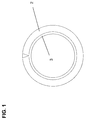
- FIG. 1 shows the core profile 2 with the adjacent bead core 3 in the side view.
- the V-cut shown in the figure was closed manually in a conventional manufacturing process and then spliced.
- FIG. 2 shows the inventive method in its basic position.
- the endless strip of material 2 in the form of a core profile rests on the feed table 4 and is held there by the first gripping means 7 in the form of a needle gripper.
- a vacuum suction 12 is arranged to receive the free end 5 of the strip of material 2.
- the first gripping means 7 is arranged on the displacement means 10, which can reciprocate between winding drum 1 and feed table 4.
- the cutting means 11 is provided for cutting the strip of material 2.
- a vacuum suction device 9 is arranged, which is turned off in the basic position shown.
- the Fig. 3 shows the first process step.
- the first gripping means 7 in the form of a needle gripper has gripped the front end of the material strip and positioned on the winding drum 1 with the traversing means 10. Then leave the first Gripping means 7, the front end 5 of the strip of material 2 going on and positioned on the winding drum. 1
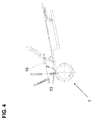
- Fig. 4 shows the second process step.
- the material strip 2 is wound on the winding drum 1, this winding process is supported on the roller 13. Meanwhile, the traversing means 10 returns to the normal position. After the winding drum 1 has completed a revolution of about 300 °, the winding process is interrupted.
- Fig. 5 shows the third process step.
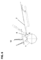
- Fig. 6 shows the fourth process step.
- the rear free end 6 of the material strip 2 is lifted with the first fixing means 8. Subsequently, the remaining piece of material strip 2 is wound on the winding drum 1, in which the winding drum 1 rotates and the traversing means 10 is tracked synchronously to this rotational movement.
- the rear free end 6 of the strip of material 2 is then deposited on the drum 1.
- the rear free end 6 thus abuts directly on the front free end 5 of the material strip 2 and is then spliced together with a laminated splice roll. Subsequently, the material strip 2 is erected in the form of a core profile with folding segments, not shown. After this process step, all components return to their normal position and the process begins again.
- Fig. 7 shows the device for carrying out the method according to the invention.
- the winding drum 1, the displacement means 10, the cutting means 11, the second fixing means 9 in the form of a vacuum suction and the feed roller 15 is shown.
- the traversing means 10 can between the winding drum 1 and the Feed table 10 are linearly reciprocated.
- the feed roller 15 supports the conveying movement of the material strip, not shown, to the winding drum. 1
Landscapes
- Engineering & Computer Science (AREA)
- Mechanical Engineering (AREA)
- Tyre Moulding (AREA)
- Replacement Of Web Rolls (AREA)
Description
- Die Erfindung betrifft ein Verfahren zum Aufwickeln und Spleißen eines Kernprofiles für einen Fahrzeugreifen mit einer Wickeltrommel.
- Bei der Reifenherstellung werden Reifenaufbauteile auf eine Wickeltrommel aufgewickelt und anschließend zu einem ringförmigen Bauteil zusammengespleißt. In der
US 3,895,986 ist zum Beispiel ein Aufwickeln eines Kernprofiles dargestellt, wobei diese Druckschrift die Herstellung eines Kernverbandes aus Kernprofil und Wulstkern betrifft. Beim Wickeln und dem anschließenden automatischen Spleißen von streifenförmigen Reifenbauteilen tritt immer wieder das Problem auf, dass das Material nach dem Ablängen des Materialstreifens eine unkontrollierte Deformation und Schrumpfung erfährt, wodurch ein automatischer Spleiß mit einer hohen Qualität verhindert wird. - Weitere Verfahren zum Spleißen von Reifen aufbauteilen auf einer Wickeltrommel sind in den Dokumenten
JP 08 025 510 A EP 1 010 651 A ,EP 0 310 417 A undUS 4,844,768 offenbart. - Der Erfindung lag die Aufgabe zugrunde, ein Verfahren bereitzustellen, mit dem auf eine einfache und präzise Weise das Aufwickeln und Zusammenspleißen eines Kernprofiles erfo lgt.
- Gelöst wird die Aufgabe durch ein Verfahren zum Aufwickeln und Spleißen eines Kernprofiles für einen Fahrzeugreifen mit einer Wickeltrommel, mit folgenden Schritten:
- Zuführten eines endlosen Materialstreifens auf einem Zuführtisch,
- Greifen des vorderen freien Endes des Materialstreifens mit einem ersten Greifmittel
- das erste Greifmittel verfahren und das freie Ende des Materialstreifens auf der Wickeltrommel fixieren
- Rotation der Wickeltrommel zum Aufwickeln des Materialstreifens
- Fixieren des hinteren Endes des Materialstreifens mit einem ersten Fixiermittel
vor und einem zweiten Fixiermittel nach der abzutrennenden Schnittfläche im Materialstreifen auf dem Zuführtisch - Durchtrennen des Materialstreifens mit einem Schneidmittel, wobei die Länge des abzutrennenden Materialstreifens im Wesentlichen dem Umfang der Wickeltrommel entspricht
- Zusammensetzen der beiden freien Enden des Materialstreifens auf der Wickeltrommel
- und Zusammenspleißen der beiden freien Enden des Materialstreifens auf der Wickeltrommel zu einem geschlossenen Ring,
- Ein Vorteil der Erfindung ist insbesondere darin zu sehen, dass durch das erfindungsgemäße Verfahren das Aufwickeln und Zusammenspleißen des Materialstreifens auf eine einfache und präzise Weise erfolgt. Vor dem Ablängen des Materialstreifens wird dieser am hinteren Ende auf beiden Seiten der durchzutrennenden Schnittfläche fest fixiert und erst dann durchtrennt. Dadurch wird jede unkontrollierte Längen- und Formänderung des Materialstreifens bzw. Kernprofiles nach dem Abschneiden verhindert. Anschließend wird das hintere Ende des Materialstreifens mit dem ersten Fixiermittel gegriffen und kontrolliert mit dem vorderen Ende des Materialstreifens auf der Wickeltrommel zusammengesetzt. Auf diese Weise erhält man einen Verbindungsspleiß mit einer hohen Fertigungsqualität. Ferner wird ein Materialausschuss beim Herstellen von Kernprofilen für Fahrzeugreifen erheblich reduziert.
- Bei der Erfindung ist vorgesehen, dass das erste Fixiermittel ein zweites Greifmittel ist, welches das hintere Ende des Materialstreifens vor dem Zusammenspleißen auf der Wickeltrommel mit dem vorderen Ende des Materialstreifens zusammensetzt. Das erste Fixiermittel hat somit sowohl die Funktion das hintere Ende des Materialstreifens auf dem Zuführtisch zu fixieren sowie das hintere Ende des Materialstreifens auf der Wickeltrommel zu positionieren.
- Weiterhin ist bei der Erfindung vorgesehen, dass das erste und zweite Greifmittel an einem Verfahrmittel angeordnet sind. Dadurch kann auf ein zweites Verfahrmittel verzichtet werden.
- In einer vorteilhaften Weiterbildung der Erfindung ist vorgesehen, dass die Greifmittel Nadel- oder Vakuumgreifer sind. Diese Art von Greifmitteln lassen sich auf einfache und effektive Weise an dem Verfahrmittel anordnen.
- Außerdem ist bei der Erfindung vorgesehen, dass das zweite Fixiermittel ein im Zuführtisch angeordneter Sauger oder Niederhalter ist. Dadurch wird das hintere Ende des Materialstreifens effektiv fixiert, so dass hinterher der Materialstreifen präzise durchtrennt werden kann.
- In einer weiteren vorteilhaften Weiterbildung der Erfindung ist vorgesehen, dass eine Vorschubrolle den Materialstreifen zur Wickeltrommel hin fördert, wobei die Vorschubrolle zur Reduktion von Materialspannungen synchron zur Umfangsgeschwindigkeit der Wickeltrommel rotiert. Auf diese Weise wird verhindert, dass der Materialstreifen unkontrollierte Längenänderungen erfährt.
- In einer weiteren vorteilhaften Weiterbildung der Erfindung ist vorgesehen, dass das Durchtrennen des Materialstreifens mit einem beheizten, doppelt schräg gestellten Quetschmesser erfolgt. Dadurch wird eine optimale Schnittfläche im Materialstreifen erzeugt, wodurch ein Verbindungsspleiß mit einer hohen Qualität erreicht wird.
- In einer weiteren vorteilhaften Weiterbildung der Erfindung ist vorgesehen, dass das Durchtrennen des Materialstreifens mit einem Hochgeschwindigkeits-Schneidverfahren erfolgt. Auf diese Weise wird die Taktzeit des Fertigungsverfahrens effektiv erhöht.
- In einer weiteren vorteilhaften Weiterbildung der Erfindung ist vorgesehen, dass nach dem Zusammensetzen des Spleisses der Spleiss mit einer lamellierten Spleissrolle verdichtet wird. Die Spleißrolle besteht aus einer Vielzahl nebeneinander liegenden kreisförmigen Scheiben, die beweglich um die Rollenachse angeordnet sind. Bei Zusammenspleißen können dadurch Unebenheiten im Verbindungsspleiß ausgeglichen werden.
- Anhand eines Ausführungsbeispiels soll die Erfindung näher erläutert werden. Es zeigen:
- Fig. 1
- zeigt ein Kernprofil mit einem anliegenden Wulstkern in der Seitenansicht,
- Fig. 2
- zeigt die Grundstellung des erfindungsgemäßen Verfahrens,
- Fig. 3 bis Fig. 6
- Verfahrensschritte 1 bis 4,
- Fig. 7
- Vorrichtung zur Durchführung des Verfahrens
- Die
Figur 1 zeigt das Kernprofil 2 mit dem anliegenden Wulstkern 3 in der Seitenansicht. Der in der Figur dargestellte V-Ausschnitt wurde bei einem herkömmlichen Herstellungsverfahren manuell geschlossen und sodann gespleißt. - Die
Figur 2 zeigt das erfindungsgemäße Verfahren in seiner Grundstellung. Der endlose Materialstreifen 2 in Form eines Kernprofils liegt auf dem Zuführtisch 4 auf und wird dort durch das erste Greifmittel 7 in Form eines Nadelgreifers gehalten. - In der Wickeltrommel 1 ist ein Vakuumsauger 12 angeordnet, der das freie Ende 5 des Materialstreifens 2 aufnehmen soll.
- Das erste Greifmittel 7 ist an dem Verfahrmittel 10 angeordnet, welches sich zwischen Wickeltrommel 1 und Zuführtisch 4 hin- und herbewegen kann. Das Schneidmittel 11 ist zum Ablängen des Materialstreifens 2 vorgesehen. Im Zuführtisch 4 ist ein Vakuumsauger 9 angeordnet, der in der gezeigten Grundstellung ausgeschaltet ist.
- Die
Fig. 3 zeigt den ersten Verfahrensschritt. Das erste Greifmittel 7 in Form eines Nadelgreifers hat das vordere Ende des Materialstreifens gegriffen und mit dem Verfahrmittel 10 auf der Wickeltrommel 1 positioniert. Anschließend lässt das erste Greifmittel 7 das vordere Ende 5 des Materialstreifens 2 los und positioniert diesen auf der Wickeltrommel 1. -
Fig. 4 zeigt den zweiten Verfahrensschritt. Der Materialstreifen 2 wird auf der Wickeltrommel 1 aufgewickelt, wobei dieser Wickelvorgang über die Rolle 13 unterstützt wird. Währenddessen fährt das Verfahrmittel 10 in die Grundstellung zurück. Nach dem die Wickeltrommel 1 eine Umdrehung von etwa 300° vollzogen hat, wird der Wickelprozess unterbrochen. -
Fig. 5 zeigt den dritten Verfahrensschritt. Das erste Fixiermittel 8, welches ebenfalls an dem Verfahrmittel 10 angeordnet ist, greift den Materialstreifen 2 vor der Schnittfläche 14. Der Vakuumsauger 9, der das zweite Fixiermittel darstellt, fixiert den Materialstreifen 2 hinter der Schnittfläche 14. Der Materialstreifen 2 wird also vor und hinter der Schnittfläche 14 fest fixiert. Anschließend wird der Materialstreifen 2 mit dem Schneidmittel 11 abgelängt. -
Fig. 6 zeigt den vierten Verfahrensschritt. Das hintere freie Ende 6 des Materialstreifens 2 wird mit dem ersten Fixiermittel 8 angehoben. Anschließend wird das Reststück des Materialstreifens 2 auf der Wickeltrommel 1 aufgewickelt, in dem die Wickeltrommel 1 sich dreht und das Verfahrmittel 10 synchron zu dieser Drehbewegung nachgeführt wird. Das hintere freie Ende 6 des Materialstreifens 2 wird sodann auf der Trommel 1 abgesetzt. Das hintere freie Ende 6 liegt somit direkt an dem vorderen freien Ende 5 des Materialstreifens 2 an und wird dann mit einer lamellierten Spleißrolle zusammen gespleißt. Anschließend wird der Materialstreifen 2 in Form eines Kernprofiles mit nicht dargestellten Klappsegmenten aufgerichtet. Nach diesem Prozessschritt fahren alle Bauteile in die Grundstellung zurück und der Vorgang beginnt von neuem. -
Fig. 7 zeigt die Vorrichtung zur Durchführung des erfindungsgemäßen Verfahrens. In dieser Ansicht ist die Wickeltrommel 1, das Verfahrmittel 10, das Schneidmittel 11, das zweite Fixiermittel 9 in Form eines Vakuumsaugers sowie die Vorschubrolle 15 dargestellt. Das Verfahrmittel 10 kann zwischen der Wickeltrommel 1 und dem Zuführtisch 10 linear hin- und herbewegt werden. Die Vorschubrolle 15 unterstützt die Förderbewegung des nicht dargestellten Materialstreifens zur Wickeltrommel 1. -
- 1
- Wickeltrommel
- 2
- Kernprofil bzw. Materialstreifen
- 3
- Wulstkern
- 4
- Zuführtsich
- 5
- vorderes freies Ende des Materialstreifens
- 6
- hinteres freies Ende des Materialstreifens
- 7
- erstes Greifmittel in Form eines Nadelgreifers
- 8
- erstes Fixiermittel in Form eines Vakuumsaugers
- 9
- zweites Fixiermittel in Form eines Vakuumsaugers
- 10
- Verfahrmittel
- 11
- Schneidmittel
- 12
- Vakuumsauger in der Wickeltrommel
- 13
- Rolle
- 14
- Schnittfläche
- 15
- Vorschubrolle
wobei das erste und zweite Greifmittel an einem Verfahrmittel angeordnet sind und
wobei das zweite Fixiermittel ein im Zuführtisch angeordneter Sauger oder Niederhalter ist.
Claims (6)
- Verfahren zum Aufwickeln und Spleißen eines Kernprofiles (2) für einen Fahrzeugreifen mit einer Wickeltrommel (1), mit folgenden Schritten:- Zuführen eines endlosen Materialstreifens (2) auf einem Zuführtisch (4),- Greifen des vorderen freien Endes (5) des Materialstreifens (2) mit einem ersten Greifmittel (7)- das erste Greifmittel (7) verfahren und das freie Ende (5) des Materialstreifens (2) auf der Wickeltrommel (1) fixieren- Rotation der Wickeltrommel (1) zum Aufwickeln des Materialstreifens (2)- Fixieren des hinteren Endes (6) des Materialstreifens (2) mit einem ersten Fixiermittel (8) vor und einem zweiten Fixiermittel (9) nach der abzutrennenden Schnittfläche (14) im Materialstreifen (2) auf dem Zuführtisch (4),- Durchtrennen des Materialstreifens (2) mit einem Schneidmittel (11), wobei die Länge des abzutrennenden Materialstreifens (2) im Wesentlichen dem Umfang der Wickeltrommel (1) entspricht- Zusammensetzen der beiden freien Enden (5, 6) des Materialstreifens (2) auf der Wickeltrommel (1).- und Zusammenspleißen der beiden freien Enden (5, 6) des Materialstreifens auf der Wickeltrommel (1) zu einem geschlossenen Ring,wobei das erste Fixiermittel (8) ein zweites Greifmittel ist, welches nach dem Greifen das hintere Ende (6) des Materialstreifens (2) synchron mit der Umfangsgeschwindigkeit der Wickeltrommel (1) verfährt und vor dem Zusammenspleißen auf der Wickeltrommel (1) mit dem vorderen Ende (5) des Materialstreifens (2) zusammensetzt,
wobei das erste und zweite Greifmittel (7, 8) an einem Verfahrmittel (10) angeordnet sind und
wobei das zweite Fixiermittel (9) ein im Zuführtisch (4) angeordneter Sauger oder Niederhalter ist. - Verfahren nach einem der vorhergehenden Ansprüche ,
dadurch gekennzeichnet, dass
die Greifmittel (7, 8) Nadel- oder Vakuumgreifer sind. - Verfahren nach einem der vorhergehenden Ansprüche,
dadurch gekennzeichnet, dass
eine Vorschubrolle (15) den Materialstreifen (2) zur Wickeltrommel (1) hin fördert, wobei die Vorschubrolle (15) zur Reduktion von Materialspannungen synchron zur Umfangsgeschwindigkeit der Wickeltrommel rotiert. - Verfahren nach einem der vorhergehenden Ansprüche,
dadurch gekennzeichnet, dass
das Durchtrennen des Materialstreifens (2) mit einem beheizten, doppelt schräg gestellten Quetschmesser (11) erfolgt. - Verfahren nach einem der vorhergehenden Ansprüche,
dadurch gekennzeichnet, dass
das Durchtrennen des Materialstreifens (2) mit einem Hochgeschwindigkeits-Schneidverfahren erfolgt. - Verfahren nach einem der vorhergehenden Ansprüche,
dadurch gekennzeichnet, dass
nach dem Zusammensetzen des Spleisses der Spleiss mit einer lamellierten Spleissrolle verdichtet wird.
Applications Claiming Priority (2)
| Application Number | Priority Date | Filing Date | Title |
|---|---|---|---|
| DE102007027557A DE102007027557A1 (de) | 2007-06-15 | 2007-06-15 | Verfahren zum Aufwickeln und Spleißen eines Kernprofiles für einen Fahrzeugreifen mit einer Wickeltrommel |
| PCT/EP2008/054786 WO2008151875A1 (de) | 2007-06-15 | 2008-04-21 | Verfahren zum aufwickeln und spleissen eines kernprofiles für einen fahrzeugreifen mit einer wickeltrommel |
Publications (2)
| Publication Number | Publication Date |
|---|---|
| EP2155482A1 EP2155482A1 (de) | 2010-02-24 |
| EP2155482B1 true EP2155482B1 (de) | 2011-04-06 |
Family
ID=39523836
Family Applications (1)
| Application Number | Title | Priority Date | Filing Date |
|---|---|---|---|
| EP08736410A Active EP2155482B1 (de) | 2007-06-15 | 2008-04-21 | Verfahren zum aufwickeln und spleissen eines kernprofiles für einen fahrzeugreifen mit einer wickeltrommel |
Country Status (4)
| Country | Link |
|---|---|
| EP (1) | EP2155482B1 (de) |
| AT (1) | ATE504423T1 (de) |
| DE (2) | DE102007027557A1 (de) |
| WO (1) | WO2008151875A1 (de) |
Families Citing this family (4)
| Publication number | Priority date | Publication date | Assignee | Title |
|---|---|---|---|---|
| EP3228443B1 (de) * | 2016-04-06 | 2020-11-04 | Continental Reifen Deutschland GmbH | Verfahren zum ablängen eines reifenbauteiles |
| FR3088575B3 (fr) * | 2018-11-15 | 2020-11-20 | Michelin & Cie | Procede et installation d'alimentation en produits elastomeriques |
| FR3088631B3 (fr) | 2018-11-15 | 2020-11-20 | Michelin & Cie | Procede et installation de transfert de devidoirs |
| CN114919216A (zh) * | 2022-05-26 | 2022-08-19 | 软控股份有限公司 | 贴合方法、贴合装置及成型机 |
Family Cites Families (10)
| Publication number | Priority date | Publication date | Assignee | Title |
|---|---|---|---|---|
| JPS5232788B2 (de) | 1973-09-21 | 1977-08-24 | ||
| JPH085141B2 (ja) * | 1987-04-14 | 1996-01-24 | 株式会社ブリヂストン | 帯状材料の貼付け装置 |
| JPS6490736A (en) * | 1987-09-30 | 1989-04-07 | Sumitomo Rubber Ind | Apex mounting and its device |
| JP2834803B2 (ja) * | 1989-11-22 | 1998-12-14 | 株式会社ブリヂストン | フィラー付きビードの成形装置 |
| JPH03166149A (ja) * | 1989-11-24 | 1991-07-18 | Bridgestone Corp | 帯状部材の供給方法および供給装置 |
| JP2524059B2 (ja) * | 1992-09-29 | 1996-08-14 | 住友ゴム工業株式会社 | ビ―ド・エ―ペックス自動アッセンブル方法及びその装置 |
| JP2528266B2 (ja) * | 1994-07-13 | 1996-08-28 | オーツタイヤ株式会社 | 軟質帯状材の定寸供給方法及び定寸供給装置 |
| DE19856720C2 (de) * | 1998-12-09 | 2001-05-17 | Continental Ag | Vorrichtung zum Transportieren und Auflegen von Materialstreifen |
| AU6946900A (en) * | 1999-09-03 | 2001-04-10 | Bartell Machinery Systems, Llc | Apparatus for stitching and seaming elastomeric fillers to tire beads |
| DE102004024715B4 (de) * | 2004-05-19 | 2017-06-01 | Continental Reifen Deutschland Gmbh | Spleißvorrichtung |
-
2007
- 2007-06-15 DE DE102007027557A patent/DE102007027557A1/de not_active Withdrawn
-
2008
- 2008-04-21 EP EP08736410A patent/EP2155482B1/de active Active
- 2008-04-21 WO PCT/EP2008/054786 patent/WO2008151875A1/de not_active Ceased
- 2008-04-21 DE DE502008003114T patent/DE502008003114D1/de active Active
- 2008-04-21 AT AT08736410T patent/ATE504423T1/de active
Also Published As
| Publication number | Publication date |
|---|---|
| ATE504423T1 (de) | 2011-04-15 |
| EP2155482A1 (de) | 2010-02-24 |
| DE102007027557A1 (de) | 2008-12-18 |
| WO2008151875A1 (de) | 2008-12-18 |
| DE502008003114D1 (de) | 2011-05-19 |
Similar Documents
| Publication | Publication Date | Title |
|---|---|---|
| DE112006003959B4 (de) | Verfahren und Vorrichtung zum Herstellen eines Reifenwulstes | |
| EP2674279B2 (de) | Verfahren zum Rollbiegen eines Profils, Profil, Verfahren zur Herstellung gebogener Profilwerkstücke, gebogenes Profilwerkstück, Vorrichtung zum Rollbiegen eines Profils sowie Extrusions- und Rollbiegelinie | |
| EP2046566B1 (de) | Zubringereinrichtung | |
| DE3232162A1 (de) | Vorrichtung zum aufbringen von reifenmaterial | |
| DE602004005090T2 (de) | Formgebung und Anlegen einer Reifengürtellage auf eine Haltevorrichtung | |
| EP2155482B1 (de) | Verfahren zum aufwickeln und spleissen eines kernprofiles für einen fahrzeugreifen mit einer wickeltrommel | |
| DE2404649A1 (de) | Reifenbaumaschine mit einer bautrommel fuer fahrzeugluftreifen unterschiedlichen durchmessers | |
| DE60126358T2 (de) | Verfahren sowie vorrichtung zum schneiden von reifenlagen | |
| DE3739652C2 (de) | ||
| DE3876930T2 (de) | Verfahren und vorrichtung zum anbringen von wulstkernen auf reifen. | |
| EP2313335B1 (de) | Vorrichtung und verfahren zum auf- und/oder abwickeln von materialbahnen | |
| DE3918023A1 (de) | Verfahren und vorrichtung zum automatischen wickeln eines haftenden bandartigen materials | |
| DE69030713T2 (de) | Vorrichtung zum Formen von mit Kernen versehenen Wülsten | |
| DE102012102222A1 (de) | Verfahren für eine Positionskorrektur der Spitzen eines Reifengürtels beim Aufwickeln auf einer Reifenaufbautrommel | |
| DE2241525A1 (de) | Vorrichtung zum anbringen von fensterflecken an umschlagrohlingen | |
| DE2209343A1 (de) | Verfahren und Vorrichtung zur kontinuierlichen Herstellung ringförmiger Teile aus verstärktem Kautschuk | |
| DE102013108184B3 (de) | Wickelmaschine und Verfahren zum Herstellen von Drahtkernen für Fahrzeugreifen | |
| DE2839245A1 (de) | Verfahren und vorrichtung zum wickeln von belegungsfolien und abstandhaltern fuer elektrische kondensatoren | |
| DE2237423A1 (de) | Rohrbaugruppe und verfahren und einrichtung zu ihrer herstellung | |
| EP1851041B1 (de) | Verfahren zum Aufwickeln und Spleissen eines Reifenaufbauteiles mit einer im Querschnittsprofil variierenden Materialdicke | |
| DE10351877B4 (de) | Schneidvorrichtung zum Abtrennen von Etiketten, Verfahren zum Abtrennen von Etiketten und Druckvorrichtung | |
| DE102006041494B3 (de) | Verfahren und Vorrichtung zur Herstellung eines Gleitlagerelementes | |
| EP2758225B1 (de) | Etikettiereinrichtung für eine thermoformanlage und verfahren | |
| DE102010015067B4 (de) | Verfahren und Vorrichtung zur Herstellung von Blechpaketen | |
| DE102006030026B4 (de) | Verfahren und Vorrichtung zum Ablängen von Materialbahnen |
Legal Events
| Date | Code | Title | Description |
|---|---|---|---|
| PUAI | Public reference made under article 153(3) epc to a published international application that has entered the european phase |
Free format text: ORIGINAL CODE: 0009012 |
|
| 17P | Request for examination filed |
Effective date: 20100115 |
|
| AK | Designated contracting states |
Kind code of ref document: A1 Designated state(s): AT BE BG CH CY CZ DE DK EE ES FI FR GB GR HR HU IE IS IT LI LT LU LV MC MT NL NO PL PT RO SE SI SK TR |
|
| AX | Request for extension of the european patent |
Extension state: AL BA MK RS |
|
| 17Q | First examination report despatched |
Effective date: 20100629 |
|
| DAX | Request for extension of the european patent (deleted) | ||
| GRAP | Despatch of communication of intention to grant a patent |
Free format text: ORIGINAL CODE: EPIDOSNIGR1 |
|
| GRAS | Grant fee paid |
Free format text: ORIGINAL CODE: EPIDOSNIGR3 |
|
| GRAA | (expected) grant |
Free format text: ORIGINAL CODE: 0009210 |
|
| AK | Designated contracting states |
Kind code of ref document: B1 Designated state(s): AT BE BG CH CY CZ DE DK EE ES FI FR GB GR HR HU IE IS IT LI LT LU LV MC MT NL NO PL PT RO SE SI SK TR |
|
| REG | Reference to a national code |
Ref country code: GB Ref legal event code: FG4D Free format text: NOT ENGLISH |
|
| REG | Reference to a national code |
Ref country code: CH Ref legal event code: EP |
|
| REG | Reference to a national code |
Ref country code: IE Ref legal event code: FG4D |
|
| REF | Corresponds to: |
Ref document number: 502008003114 Country of ref document: DE Date of ref document: 20110519 Kind code of ref document: P |
|
| REG | Reference to a national code |
Ref country code: DE Ref legal event code: R096 Ref document number: 502008003114 Country of ref document: DE Effective date: 20110519 |
|
| REG | Reference to a national code |
Ref country code: NL Ref legal event code: T3 |
|
| PG25 | Lapsed in a contracting state [announced via postgrant information from national office to epo] |
Ref country code: SI Free format text: LAPSE BECAUSE OF FAILURE TO SUBMIT A TRANSLATION OF THE DESCRIPTION OR TO PAY THE FEE WITHIN THE PRESCRIBED TIME-LIMIT Effective date: 20110406 |
|
| LTIE | Lt: invalidation of european patent or patent extension |
Effective date: 20110406 |
|
| REG | Reference to a national code |
Ref country code: SK Ref legal event code: T3 Ref document number: E 9813 Country of ref document: SK |
|
| REG | Reference to a national code |
Ref country code: IE Ref legal event code: FD4D |
|
| BERE | Be: lapsed |
Owner name: CONTINENTAL REIFEN DEUTSCHLAND G.M.B.H. Effective date: 20110430 |
|
| PG25 | Lapsed in a contracting state [announced via postgrant information from national office to epo] |
Ref country code: PT Free format text: LAPSE BECAUSE OF FAILURE TO SUBMIT A TRANSLATION OF THE DESCRIPTION OR TO PAY THE FEE WITHIN THE PRESCRIBED TIME-LIMIT Effective date: 20110808 Ref country code: LT Free format text: LAPSE BECAUSE OF FAILURE TO SUBMIT A TRANSLATION OF THE DESCRIPTION OR TO PAY THE FEE WITHIN THE PRESCRIBED TIME-LIMIT Effective date: 20110406 Ref country code: SE Free format text: LAPSE BECAUSE OF FAILURE TO SUBMIT A TRANSLATION OF THE DESCRIPTION OR TO PAY THE FEE WITHIN THE PRESCRIBED TIME-LIMIT Effective date: 20110406 Ref country code: NO Free format text: LAPSE BECAUSE OF FAILURE TO SUBMIT A TRANSLATION OF THE DESCRIPTION OR TO PAY THE FEE WITHIN THE PRESCRIBED TIME-LIMIT Effective date: 20110706 Ref country code: HR Free format text: LAPSE BECAUSE OF FAILURE TO SUBMIT A TRANSLATION OF THE DESCRIPTION OR TO PAY THE FEE WITHIN THE PRESCRIBED TIME-LIMIT Effective date: 20110406 |
|
| PG25 | Lapsed in a contracting state [announced via postgrant information from national office to epo] |
Ref country code: FI Free format text: LAPSE BECAUSE OF FAILURE TO SUBMIT A TRANSLATION OF THE DESCRIPTION OR TO PAY THE FEE WITHIN THE PRESCRIBED TIME-LIMIT Effective date: 20110406 Ref country code: LV Free format text: LAPSE BECAUSE OF FAILURE TO SUBMIT A TRANSLATION OF THE DESCRIPTION OR TO PAY THE FEE WITHIN THE PRESCRIBED TIME-LIMIT Effective date: 20110406 Ref country code: GR Free format text: LAPSE BECAUSE OF FAILURE TO SUBMIT A TRANSLATION OF THE DESCRIPTION OR TO PAY THE FEE WITHIN THE PRESCRIBED TIME-LIMIT Effective date: 20110707 Ref country code: MC Free format text: LAPSE BECAUSE OF NON-PAYMENT OF DUE FEES Effective date: 20110430 Ref country code: ES Free format text: LAPSE BECAUSE OF FAILURE TO SUBMIT A TRANSLATION OF THE DESCRIPTION OR TO PAY THE FEE WITHIN THE PRESCRIBED TIME-LIMIT Effective date: 20110717 Ref country code: CY Free format text: LAPSE BECAUSE OF FAILURE TO SUBMIT A TRANSLATION OF THE DESCRIPTION OR TO PAY THE FEE WITHIN THE PRESCRIBED TIME-LIMIT Effective date: 20110406 Ref country code: IS Free format text: LAPSE BECAUSE OF FAILURE TO SUBMIT A TRANSLATION OF THE DESCRIPTION OR TO PAY THE FEE WITHIN THE PRESCRIBED TIME-LIMIT Effective date: 20110806 |
|
| PG25 | Lapsed in a contracting state [announced via postgrant information from national office to epo] |
Ref country code: MT Free format text: LAPSE BECAUSE OF FAILURE TO SUBMIT A TRANSLATION OF THE DESCRIPTION OR TO PAY THE FEE WITHIN THE PRESCRIBED TIME-LIMIT Effective date: 20110406 |
|
| PG25 | Lapsed in a contracting state [announced via postgrant information from national office to epo] |
Ref country code: EE Free format text: LAPSE BECAUSE OF FAILURE TO SUBMIT A TRANSLATION OF THE DESCRIPTION OR TO PAY THE FEE WITHIN THE PRESCRIBED TIME-LIMIT Effective date: 20110406 Ref country code: IE Free format text: LAPSE BECAUSE OF FAILURE TO SUBMIT A TRANSLATION OF THE DESCRIPTION OR TO PAY THE FEE WITHIN THE PRESCRIBED TIME-LIMIT Effective date: 20110406 Ref country code: BE Free format text: LAPSE BECAUSE OF NON-PAYMENT OF DUE FEES Effective date: 20110430 |
|
| PLBE | No opposition filed within time limit |
Free format text: ORIGINAL CODE: 0009261 |
|
| STAA | Information on the status of an ep patent application or granted ep patent |
Free format text: STATUS: NO OPPOSITION FILED WITHIN TIME LIMIT |
|
| PG25 | Lapsed in a contracting state [announced via postgrant information from national office to epo] |
Ref country code: PL Free format text: LAPSE BECAUSE OF FAILURE TO SUBMIT A TRANSLATION OF THE DESCRIPTION OR TO PAY THE FEE WITHIN THE PRESCRIBED TIME-LIMIT Effective date: 20110406 Ref country code: RO Free format text: LAPSE BECAUSE OF FAILURE TO SUBMIT A TRANSLATION OF THE DESCRIPTION OR TO PAY THE FEE WITHIN THE PRESCRIBED TIME-LIMIT Effective date: 20110406 Ref country code: DK Free format text: LAPSE BECAUSE OF FAILURE TO SUBMIT A TRANSLATION OF THE DESCRIPTION OR TO PAY THE FEE WITHIN THE PRESCRIBED TIME-LIMIT Effective date: 20110406 |
|
| 26N | No opposition filed |
Effective date: 20120110 |
|
| REG | Reference to a national code |
Ref country code: DE Ref legal event code: R097 Ref document number: 502008003114 Country of ref document: DE Effective date: 20120110 |
|
| REG | Reference to a national code |
Ref country code: CH Ref legal event code: PL |
|
| GBPC | Gb: european patent ceased through non-payment of renewal fee |
Effective date: 20120421 |
|
| PG25 | Lapsed in a contracting state [announced via postgrant information from national office to epo] |
Ref country code: LI Free format text: LAPSE BECAUSE OF NON-PAYMENT OF DUE FEES Effective date: 20120430 Ref country code: GB Free format text: LAPSE BECAUSE OF NON-PAYMENT OF DUE FEES Effective date: 20120421 Ref country code: CH Free format text: LAPSE BECAUSE OF NON-PAYMENT OF DUE FEES Effective date: 20120430 |
|
| PG25 | Lapsed in a contracting state [announced via postgrant information from national office to epo] |
Ref country code: LU Free format text: LAPSE BECAUSE OF NON-PAYMENT OF DUE FEES Effective date: 20110421 |
|
| PG25 | Lapsed in a contracting state [announced via postgrant information from national office to epo] |
Ref country code: BG Free format text: LAPSE BECAUSE OF FAILURE TO SUBMIT A TRANSLATION OF THE DESCRIPTION OR TO PAY THE FEE WITHIN THE PRESCRIBED TIME-LIMIT Effective date: 20110706 |
|
| PG25 | Lapsed in a contracting state [announced via postgrant information from national office to epo] |
Ref country code: TR Free format text: LAPSE BECAUSE OF FAILURE TO SUBMIT A TRANSLATION OF THE DESCRIPTION OR TO PAY THE FEE WITHIN THE PRESCRIBED TIME-LIMIT Effective date: 20110406 |
|
| PG25 | Lapsed in a contracting state [announced via postgrant information from national office to epo] |
Ref country code: HU Free format text: LAPSE BECAUSE OF FAILURE TO SUBMIT A TRANSLATION OF THE DESCRIPTION OR TO PAY THE FEE WITHIN THE PRESCRIBED TIME-LIMIT Effective date: 20110406 |
|
| REG | Reference to a national code |
Ref country code: FR Ref legal event code: PLFP Year of fee payment: 9 |
|
| REG | Reference to a national code |
Ref country code: FR Ref legal event code: PLFP Year of fee payment: 10 |
|
| REG | Reference to a national code |
Ref country code: FR Ref legal event code: PLFP Year of fee payment: 11 |
|
| PGFP | Annual fee paid to national office [announced via postgrant information from national office to epo] |
Ref country code: SK Payment date: 20180420 Year of fee payment: 11 |
|
| PGFP | Annual fee paid to national office [announced via postgrant information from national office to epo] |
Ref country code: AT Payment date: 20180419 Year of fee payment: 11 |
|
| REG | Reference to a national code |
Ref country code: AT Ref legal event code: MM01 Ref document number: 504423 Country of ref document: AT Kind code of ref document: T Effective date: 20190421 |
|
| REG | Reference to a national code |
Ref country code: SK Ref legal event code: MM4A Ref document number: E 9813 Country of ref document: SK Effective date: 20190421 |
|
| PG25 | Lapsed in a contracting state [announced via postgrant information from national office to epo] |
Ref country code: SK Free format text: LAPSE BECAUSE OF NON-PAYMENT OF DUE FEES Effective date: 20190421 Ref country code: AT Free format text: LAPSE BECAUSE OF NON-PAYMENT OF DUE FEES Effective date: 20190421 |
|
| PG25 | Lapsed in a contracting state [announced via postgrant information from national office to epo] |
Ref country code: IT Free format text: LAPSE BECAUSE OF NON-PAYMENT OF DUE FEES Effective date: 20200421 |
|
| P01 | Opt-out of the competence of the unified patent court (upc) registered |
Effective date: 20230602 |
|
| REG | Reference to a national code |
Ref country code: DE Ref legal event code: R081 Ref document number: 502008003114 Country of ref document: DE Owner name: CONTINENTAL REIFEN DEUTSCHLAND GMBH, DE Free format text: FORMER OWNER: CONTINENTAL REIFEN DEUTSCHLAND GMBH, 30165 HANNOVER, DE |
|
| PGFP | Annual fee paid to national office [announced via postgrant information from national office to epo] |
Ref country code: NL Payment date: 20240418 Year of fee payment: 17 |
|
| PGFP | Annual fee paid to national office [announced via postgrant information from national office to epo] |
Ref country code: CZ Payment date: 20240412 Year of fee payment: 17 |
|
| PGFP | Annual fee paid to national office [announced via postgrant information from national office to epo] |
Ref country code: DE Payment date: 20250430 Year of fee payment: 18 |
|
| PGFP | Annual fee paid to national office [announced via postgrant information from national office to epo] |
Ref country code: FR Payment date: 20250424 Year of fee payment: 18 |
|
| REG | Reference to a national code |
Ref country code: NL Ref legal event code: MM Effective date: 20250501 |
|
| PGFP | Annual fee paid to national office [announced via postgrant information from national office to epo] |
Ref country code: IT Payment date: 20240424 Year of fee payment: 17 |
|
| PG25 | Lapsed in a contracting state [announced via postgrant information from national office to epo] |
Ref country code: NL Free format text: LAPSE BECAUSE OF NON-PAYMENT OF DUE FEES Effective date: 20250501 |
|
| PG25 | Lapsed in a contracting state [announced via postgrant information from national office to epo] |
Ref country code: CZ Free format text: LAPSE BECAUSE OF NON-PAYMENT OF DUE FEES Effective date: 20250421 |
|
| PG25 | Lapsed in a contracting state [announced via postgrant information from national office to epo] |
Ref country code: IT Free format text: LAPSE BECAUSE OF NON-PAYMENT OF DUE FEES Effective date: 20200421 |
|
| PGRI | Patent reinstated in contracting state [announced from national office to epo] |
Ref country code: IT Effective date: 20251031 |