EP2154442A1 - Self-cleaning device of filtering net and air conditioner having it - Google Patents
Self-cleaning device of filtering net and air conditioner having it Download PDFInfo
- Publication number
- EP2154442A1 EP2154442A1 EP07816595A EP07816595A EP2154442A1 EP 2154442 A1 EP2154442 A1 EP 2154442A1 EP 07816595 A EP07816595 A EP 07816595A EP 07816595 A EP07816595 A EP 07816595A EP 2154442 A1 EP2154442 A1 EP 2154442A1
- Authority
- EP
- European Patent Office
- Prior art keywords
- dust
- filtering net
- air conditioner
- basal body
- brush roll
- Prior art date
- Legal status (The legal status is an assumption and is not a legal conclusion. Google has not performed a legal analysis and makes no representation as to the accuracy of the status listed.)
- Granted
Links
Images



Classifications
-
- F—MECHANICAL ENGINEERING; LIGHTING; HEATING; WEAPONS; BLASTING
- F24—HEATING; RANGES; VENTILATING
- F24F—AIR-CONDITIONING; AIR-HUMIDIFICATION; VENTILATION; USE OF AIR CURRENTS FOR SCREENING
- F24F1/00—Room units for air-conditioning, e.g. separate or self-contained units or units receiving primary air from a central station
- F24F1/0007—Indoor units, e.g. fan coil units
- F24F1/0043—Indoor units, e.g. fan coil units characterised by mounting arrangements
- F24F1/0057—Indoor units, e.g. fan coil units characterised by mounting arrangements mounted in or on a wall
-
- F—MECHANICAL ENGINEERING; LIGHTING; HEATING; WEAPONS; BLASTING
- F24—HEATING; RANGES; VENTILATING
- F24F—AIR-CONDITIONING; AIR-HUMIDIFICATION; VENTILATION; USE OF AIR CURRENTS FOR SCREENING
- F24F8/00—Treatment, e.g. purification, of air supplied to human living or working spaces otherwise than by heating, cooling, humidifying or drying
- F24F8/90—Cleaning of purification apparatus
-
- F—MECHANICAL ENGINEERING; LIGHTING; HEATING; WEAPONS; BLASTING
- F24—HEATING; RANGES; VENTILATING
- F24F—AIR-CONDITIONING; AIR-HUMIDIFICATION; VENTILATION; USE OF AIR CURRENTS FOR SCREENING
- F24F1/00—Room units for air-conditioning, e.g. separate or self-contained units or units receiving primary air from a central station
- F24F1/0007—Indoor units, e.g. fan coil units
- F24F1/0071—Indoor units, e.g. fan coil units with means for purifying supplied air
- F24F1/0073—Indoor units, e.g. fan coil units with means for purifying supplied air characterised by the mounting or arrangement of filters
-
- F—MECHANICAL ENGINEERING; LIGHTING; HEATING; WEAPONS; BLASTING
- F24—HEATING; RANGES; VENTILATING
- F24F—AIR-CONDITIONING; AIR-HUMIDIFICATION; VENTILATION; USE OF AIR CURRENTS FOR SCREENING
- F24F8/00—Treatment, e.g. purification, of air supplied to human living or working spaces otherwise than by heating, cooling, humidifying or drying
- F24F8/10—Treatment, e.g. purification, of air supplied to human living or working spaces otherwise than by heating, cooling, humidifying or drying by separation, e.g. by filtering
-
- F—MECHANICAL ENGINEERING; LIGHTING; HEATING; WEAPONS; BLASTING
- F24—HEATING; RANGES; VENTILATING
- F24F—AIR-CONDITIONING; AIR-HUMIDIFICATION; VENTILATION; USE OF AIR CURRENTS FOR SCREENING
- F24F8/00—Treatment, e.g. purification, of air supplied to human living or working spaces otherwise than by heating, cooling, humidifying or drying
- F24F8/10—Treatment, e.g. purification, of air supplied to human living or working spaces otherwise than by heating, cooling, humidifying or drying by separation, e.g. by filtering
- F24F8/108—Treatment, e.g. purification, of air supplied to human living or working spaces otherwise than by heating, cooling, humidifying or drying by separation, e.g. by filtering using dry filter elements
Definitions
- the present invention relates to an air conditioner device, especially to a self-cleaning device with the characteristic of conveniently dedusting, good dedusting effect and less noise.
- Room air conditioner commonly adopt a heat exchanger to adjust the indoor temperature, generally speaking, hood a dust filtering device, a dust filtering net on the heat exchanger to prevent the dust.
- the dust filtering net is deposited with dust after a period of operating of the room air conditioner.
- Usually manually cleaning is needed to clean the dust on the filtering net, which is quite troublesome.
- a self-cleaning device which can automatically clean the dust on the filtering net without artificial interference. This device is very convenient to the users.
- Chinese application No. 200510120265.6 disclosed a kind of air conditioner with a indoor unit which has the function of automatically cleaning the air filter and the drive mechanism with simple that can exactly drive the dust absorbing section.
- On the indoor unit of the air conditioner there is mounted an air filter on the upstream side of the heat exchanger, a slidable suction nozzle having a suction port facing the air filter and sucking dust stuck to the air filter, a drive source for driving the suction nozzle through the drive mechanism, an exhaust device communicating with the suction nozzle and sucking and exhausting dust together with air, and a communicating means for allowing the exhaust device and the suction nozzle to communicate with each other.
- the drive mechanism is composed of a diving shaft connected to the drive source, a worm gear slidably mounted to the driving shaft and silding integrally with the suction nozzle, and a rack meshed with the worm gear.
- the present invention discloses a kind of self-cleaning device with good dedusting effects in short time and less noise, considering the above disadvantages, . And the device has reliable structure and durability.
- the present invention provides a self-cleaning device of a filtering net which makes less noise, has good dedusting effects and firmly structure.
- the other purpose of the present invention is to provide an air conditioner having the self-cleaning device of the filtering net, and more particularly an air conditioner having a sliding panel.
- a self-cleaning device of a filtering net disposed in a wall-mounted air conditioner including: a filtering net of an air conditioner disposed on the outside of a heat exchanger, which includes an upper filtering net and a front filtering net, and is used for absorbing the dust of the air passing through the heat exchanger; a dust sweeping assembly with a detachable brush, which is disposed on the outside of the filtering net and is used for sweeping the dust on the filtering net; a drive device comprising a drive motor and a transmission mechanism, which is used for driving the dust sweeping assembly to slide on the filtering net to sweep off the dust; a dust box which is used for collecting the dust and is detachably disposed in the air conditioner to clear up the dust in the box; and a dust exchanging device which is disposed on the left or right side of the filtering net, and is used for transferring the dust swept out by the dust sweeping
- An air conditioner having the above self-cleaning device of the filtering net includes: a filtering net of an air conditioner disposed outside the heat exchanger, a dust box disposed on the left bottom and right bottom portion of the filtering net, and a panel set on the outside of the filtering net and the dust box, the characteristic is that: the panel includes a upper fixed panel and a lower panel which can slide rightwards or leftwards to conveniently open the dust box.
- the dust sweeping assembly includes a basal body with "L" in shape and a slide locating device, the basal body is composed by an upper basal body and a front basal body which are respectively correspondingly located on the outside of the upper filtering net and the front filtering net, the slide locating device located on both ends of the basal body is respectively located in the slide way of the upside of the upper filtering net and the downside of the front filtering net, the slide locating device includes a sliding wheel that can slide along the slide way and a locating block used for preventing the basal body deviating.
- Chambers are respectively located in the upper basal body and the front basal body, A brush assembly thrusts into the chambers from the outside of the basal body and is attached with the filtering net inside the basal body.
- Turnover covers are provided on the basal body corresponding to the chambers to prevent the brush assembly from detaching, and one side of the turnover covers are pin-jointed to the basal body by bolts or buckles.
- the drive motor is a step motor, which is located on the left or right side of the joint of the upper filtering net and the front filtering net
- the transmission mechanism is composed of a drive shaft connected with the drive motor, a wormgear that is freely slidablely located on the drive shaft and rotates together with the drive shaft, and a rack meshed with the wormgear.
- the drive shaft with the structure of regular polygonal column is located at the joint of the upper filtering net and the front filtering net in parallel with the rack and, the rack is smoothly located between the upper filtering net and the front filtering net, the drive shaft is disposed above the rack, the wormgear is pin-jointed inside the bend portion of the 'L' shape basal body, and both ends of the rack and/or the drive shaft have travel switches.
- the transmission mechanism is composed of a drive shaft with external thread which is connected with the drive motor, and an internal thread which is located on the basal body and screwed on the external thread, the basal body is slidablely located on the screw in parallel with the drive shaft.
- the dust exchanging device is a rectangular frame, in which a brush roll for absorbing the dust is pin-jointed brush rollin parallel with the side edge of the filtering net, the brush roll is a circular cylinder or semi-cylinder or elliptical column, a reset mechanism set on the brush roll can be made of a spring or a tension spring, the dust exchanging device is respectively located in the slots set on the left or right side of the upper filtering net and the front filtering net, and there is a communicated dust passage with downward inclination in the bottom of the slots, a dust box slot whose interior is communicated with the slot is located under the slot set on the side of the front filtering net, the dust box being a box structure with a opening that is communicated with the bottom of the slot is pull-pluggably located in the dust box.
- Blocks are pin-jointed at both ends of the brush roll, the blocks can freely rotate to the reverse direction of the filtering net and impulse the brush roll to synchronously rotate to the direction of the filtering net, the blocks have reset mechanism, and in the reset state the blocks are oriented to the direction of the hatch of the frame.
- the inward extended baffle with a reset mechanism which is parallel with the brush roll is pin-jointed on the side of the brush roll near the filtering net in the frame of the dust exchanging device, a felt is set on the baffle's side near the brush roll to realize a second dust exchanging, a soft baffle is aslant set along the tangent outwards on the other side of the brush roll, and is deflected away from the filtering net.
- the exchanging process of the dust includes: the brush on the duct sweeping assembly moving the dust on the filtering net, the sweeping assembly sliding to the dust exchanging device, the block being pushed to press into the frame by the sweeping assembly when it passes through the dust exchanging device, the dust being adsorbed and swept by the brush and the soft baffle in turn, the block being reset after passing the sweeping assembly, the sweeping assembly driving the blocks on both sides of the dust exchanging device to rotate and pushing the brush roll to rotate when it reversely passing through the dust exchanging device, the dust blocked by the brush roll being put into the dust passage and then into the dust box through a dust passage, the brush roll being reset by spring or tension spring after the sweeping assembly slides over the dust exchanging device, the residual dust on the brush roll being cleaned again by the baffle, the brush roll and the soft baffle being reset to seal the hatch of the frame to prevent the dust from being taken out.
- the self-cleaning device of the air conditioner of the invention can clear away the dust on the filtering net in a short time with good dedusting effects, less noise, and simple structure with reliability and durability by taking the above mentioned mechanical structure and technical solution.
- the self-cleaning device of filtering net of the invention which is set in the wall-hanging type air conditioner includes: a filtering net 1 disposed outside of the heat exchanger which includes an upper filtering net 11 and a front filtering net 12, and is used for absorbing the dust of the air passing through the heat exchanger; a dust sweeping assembly 2 with a detachable brush 20 ( shown in FIG.
- a drive device 3 with a drive motor 31 and a transmission mechanism, which is used for driving the dust sweeping assembly 2 to slide on the filtering net 1 to sweep off the dust
- a dust box 4 which is used for collecting the dust and is detachably disposed in the air conditioner to clear up the dust in the box
- a dust exchanging device 5 which is disposed on the left or right side of the filtering net 1, and is used for transferring the dust swept out by the sweeping assembly 2 into the dust box 4.
- the dust exchanging device 5 and the dust box 4 are disposed on the left side of the filtering net 1
- the dust exchanging device 5 includes two parts which are respectively disposed on the left side of the upper filtering net 11 and the front filtering net 12, the dust box 4 is located under the dust exchanging device 5 on the left side of the front filtering net 12;
- the drive motor 31 is disposed on the right side of the filtering net 1.
- the dust sweeping assembly includes a basal body 21 with 'L' in shape and a slide locating device, that the basal body is composed of an upper basal body 211 and a front basal body 212 which are respectively correspondingly located outside the upper filtering net 11 and the front filtering net 12.
- the basal body 21 is holistically covered on the filtering net 1, and is fixedly disposed in the slide way of the upside of the upper filtering net 11 and the downside of the front filtering net 12 through the slide locating device respectively disposed on the both ends of the basal body.
- the slide locating device includes a sliding wheel 22 that can slide along the slide way and a locating block 23 used for preventing the basal body from deviating, which can decrease the vibration of the sliding of the sweeping assembly to reduce the noise.
- chambers are respectively located in the upper basal body 211 and the front basal body 212 along their length direction.
- a brush assembly 20 thrusts into the chambers from the outside of the basal body and is attached with the filtering net inside the basal body to realize best sweeping effects.
- Turnover covers 24 are provided on the basal body 21 corresponding to the chambers to prevent the brush assembly 20 from detaching.
- the upside of the turnover cover 24 corresponding to the front basal body 212 is pin-joined with the basal body 21, and the downside of the turnover cover 24 corresponding to the upper basal body 211 is pin-joined with the basal body 21.
- Both of the two turnover covers turn up towards the middle of the bend of the 'L' shaped basal body, and the turnover cover 24 is fixed on the basal body 21 by bolts or buckles.
- the buckle mechanism (not shown in the FIGs) is non-roundness buttons being usually shape of rectangle or ellipse set on the basal body.
- An opening matching with the shape of the buttons is disposed on the position of the turnover cover corresponding to the buttons. The buttons passed through the opening are rotated to dislocate the opening and fix the turnover cover after the turnover cover is closed, which makes it easy to change when the brush is frayed.
- the drive motor 31 is a step motor, , which is located on the right side of the joint of the upper filtering net 11 and the front filtering net 12 and fixed inside the electric motor box 311.
- the transmission mechanism is composed of a drive shaft 32 connected with the drive motor 31, the wormgear 33 that is freely slidable located on the drive shaft 32 and rotate together with the drive shaft, and the rack 34 meshed with the wormgear 33.
- the drive shaft with the structure of regular polygonal column is parallel with the rack 34 and located at the joint of the upper filtering net 11 and the front filtering net 12.
- the rack 34 is smoothly located between the upper filtering net 11 and the front filtering net 12, and the drive shaft 32 is located above the rack 34.
- the wormgear 33 is pin-jointed inside the bend portion of the 'L' in shape of the basal body 21 (shown as Fig.6 ), and both ends of the rack 34 and/or the drive shaft 32 have travel switches( not shown in the figure) which make the step motor to reversely run when the sweeping assembly reaches the designated position, which cooperates with the slide locating device to reduce the driving noise.
- the transmission mechanism is composed of the drive shaft with external thread which is connected with the drive motor, and the internal thread which is located on the basal body and screwed on the external thread, the basal body is slidable located on the screw in parallel with the drive shaft, which has the same principle as the above mentioned drive system (not shown in the figure).
- the dust exchanging device 5 is a rectangular frame in which a brush roll 51 for absorbing the dust is pin-jointed in parallel with the side edge of the filtering net 1, the brush roll 51 is a circular cylinder or semi-cylinder or elliptical column a reset mechanism 511 set on the brush roll can be made of the spring or tension spring, the dust exchanging device 5 is respectively located in the slots 6 set on the left side of the upper filtering net 11 and the front filtering net 12, and there is a communicated dust passage 7 with downward inclination in the bottom of the slots 6, the dust box slot 8 whose interior is communicated with the slot 6 is located under the slot 6 of the left side of the front filtering net 12.
- the dust box 4 being a box structure with an opening 41 that is communicated with the dust passage 7 is pull-pluggably located in the dust box slot 8.
- Elastic lugs 50 (shown as Fig.4 ) are respectively set on the lateral part of the dust exchanging device and the bottom of the dust box to fix the dust exchanging device 5 and the dust box 4 which are independent each other in the slots and the inner dust box slots to realize the fixing.
- the blocks 52 are pin-jointed at both ends of the brush roll 51, the blocks can freely rotate to the reverse direction of the filtering net or to the direction of the filtering net to impulse the brush roll 51 to synchronously rotate, the blocks 52 have the reset mechanism 521, and in the reset state the blocks are oriented to the direction of the hatch of the frame. The block can be reset whenever it rotate to any direction.
- the inward extended baffle 53 with a reset mechanism 531 which is parallel with the brush roll 51 is pin-jointed on the side of the brush roll 51 near the filtering net 1 in the frame of the dust exchanging device 5, the felt is set on the baffle's side near the brush roll 51 to realize a second dust exchanging, a soft baffle 54 is aslant set along the tangent outwards on the other side of the brush roll 51, and is deflected away from the filtering net 1.
- the exchanging process of the dust includes: the brush on the duct sweeping assembly 2 moving the dust on the filtering net 1, the sweeping assembly 2 sliding to the dust exchanging device 5, the block 52 being pushed to press into the frame by the sweeping assembly 2 when it passes through the dust exchanging device 5, the dust being adsorbed and swept by the brush roll 51 and the soft baffle 54 in turn, the block 52 being reset after passing the sweeping assembly 5 ( shown as Fig.7 ), the sweeping assembly 2 driving the blocks on both sides of the dust exchanging device to rotate and pushing the brush roll to rotate when it reversely passing through the dust exchanging device 5, the dust blocked by the brush roll 51 being put into the dust passage 7 and then into the dust box 4 through a dust passage 7, the brush roll 51 being reset by spring or tension spring after the sweeping assembly 2 slides over the dust exchanging device 5, the residual dust on the brush roll 51 being cleaned again by the baffle 53, the brush roll 51 and the soft baffle 54 being reset to seal the hatch of the frame to prevent the dust being taken out.
- the dust can be stored in the dust box after sweeping each time, which can be cleaned every two to three years according to the operating environment.
- the invention improves the air-conditioner panel compared with the integral panel of the prior art for the convenience of cleaning the dust in the dust box. In the prior art, the panel must be entirely opened to clean the dust box, which is inconvenient.
- the present invention adopts a panel which is divided into the upper part and the lower part, the connection relation of the upper fixed panel 9 and the air-conditioner is kept fixed, and the lower panel is the slide panel 10 which can slide rightward and leftward and cover the outside of the dust box 4. It can be taken out for cleaning only by rightward sliding the panel 10 for a distance of the dust box in the process of cleaning. The panel can be replaced after cleaning, which is very convenient.
- the self-cleaning device of the air conditioner of the invention can clear away the dust on the filtering net in a short time with good dedusting effects, less noise, and simple structure with reliability and durability.
Landscapes
- Engineering & Computer Science (AREA)
- Chemical & Material Sciences (AREA)
- Combustion & Propulsion (AREA)
- Mechanical Engineering (AREA)
- General Engineering & Computer Science (AREA)
- Filtering Of Dispersed Particles In Gases (AREA)
- Cleaning In General (AREA)
- Air Filters, Heat-Exchange Apparatuses, And Housings Of Air-Conditioning Units (AREA)
Abstract
Description
- The present invention relates to an air conditioner device, especially to a self-cleaning device with the characteristic of conveniently dedusting, good dedusting effect and less noise.
- Room air conditioner commonly adopt a heat exchanger to adjust the indoor temperature, generally speaking, hood a dust filtering device, a dust filtering net on the heat exchanger to prevent the dust. Previously, the dust filtering net is deposited with dust after a period of operating of the room air conditioner. Usually manually cleaning is needed to clean the dust on the filtering net, which is quite troublesome. So we invent a self-cleaning device, which can automatically clean the dust on the filtering net without artificial interference. This device is very convenient to the users.
- Chinese application No.
200510120265.6 - The present invention discloses a kind of self-cleaning device with good dedusting effects in short time and less noise, considering the above disadvantages, . And the device has reliable structure and durability.
- The technical problem to be solved in the present invention overcomes the disadvantage in the prior art, the present invention provides a self-cleaning device of a filtering net which makes less noise, has good dedusting effects and firmly structure.
- The other purpose of the present invention is to provide an air conditioner having the self-cleaning device of the filtering net, and more particularly an air conditioner having a sliding panel.
- In order to solve the above technical problem, the basic conception of the technical scheme of the present invention is as follows: a self-cleaning device of a filtering net disposed in a wall-mounted air conditioner, including: a filtering net of an air conditioner disposed on the outside of a heat exchanger, which includes an upper filtering net and a front filtering net, and is used for absorbing the dust of the air passing through the heat exchanger; a dust sweeping assembly with a detachable brush, which is disposed on the outside of the filtering net and is used for sweeping the dust on the filtering net; a drive device comprising a drive motor and a transmission mechanism, which is used for driving the dust sweeping assembly to slide on the filtering net to sweep off the dust; a dust box which is used for collecting the dust and is detachably disposed in the air conditioner to clear up the dust in the box; and a dust exchanging device which is disposed on the left or right side of the filtering net, and is used for transferring the dust swept out by the dust sweeping assembly into the dust box.
- An air conditioner having the above self-cleaning device of the filtering net includes: a filtering net of an air conditioner disposed outside the heat exchanger, a dust box disposed on the left bottom and right bottom portion of the filtering net, and a panel set on the outside of the filtering net and the dust box, the characteristic is that: the panel includes a upper fixed panel and a lower panel which can slide rightwards or leftwards to conveniently open the dust box.
- The dust sweeping assembly includes a basal body with "L" in shape and a slide locating device, the basal body is composed by an upper basal body and a front basal body which are respectively correspondingly located on the outside of the upper filtering net and the front filtering net, the slide locating device located on both ends of the basal body is respectively located in the slide way of the upside of the upper filtering net and the downside of the front filtering net, the slide locating device includes a sliding wheel that can slide along the slide way and a locating block used for preventing the basal body deviating.
- Chambers are respectively located in the upper basal body and the front basal body, A brush assembly thrusts into the chambers from the outside of the basal body and is attached with the filtering net inside the basal body. Turnover covers are provided on the basal body corresponding to the chambers to prevent the brush assembly from detaching, and one side of the turnover covers are pin-jointed to the basal body by bolts or buckles.
- The drive motor is a step motor, which is located on the left or right side of the joint of the upper filtering net and the front filtering net, the transmission mechanism is composed of a drive shaft connected with the drive motor, a wormgear that is freely slidablely located on the drive shaft and rotates together with the drive shaft, and a rack meshed with the wormgear.
- The drive shaft with the structure of regular polygonal column is located at the joint of the upper filtering net and the front filtering net in parallel with the rack and, the rack is smoothly located between the upper filtering net and the front filtering net, the drive shaft is disposed above the rack, the wormgear is pin-jointed inside the bend portion of the 'L' shape basal body, and both ends of the rack and/or the drive shaft have travel switches.
- The transmission mechanism is composed of a drive shaft with external thread which is connected with the drive motor, and an internal thread which is located on the basal body and screwed on the external thread, the basal body is slidablely located on the screw in parallel with the drive shaft.
- The dust exchanging device is a rectangular frame, in which a brush roll for absorbing the dust is pin-jointed brush rollin parallel with the side edge of the filtering net, the brush roll is a circular cylinder or semi-cylinder or elliptical column, a reset mechanism set on the brush roll can be made of a spring or a tension spring, the dust exchanging device is respectively located in the slots set on the left or right side of the upper filtering net and the front filtering net, and there is a communicated dust passage with downward inclination in the bottom of the slots, a dust box slot whose interior is communicated with the slot is located under the slot set on the side of the front filtering net, the dust box being a box structure with a opening that is communicated with the bottom of the slot is pull-pluggably located in the dust box.
- Blocks are pin-jointed at both ends of the brush roll, the blocks can freely rotate to the reverse direction of the filtering net and impulse the brush roll to synchronously rotate to the direction of the filtering net, the blocks have reset mechanism, and in the reset state the blocks are oriented to the direction of the hatch of the frame.
- The inward extended baffle with a reset mechanism which is parallel with the brush roll is pin-jointed on the side of the brush roll near the filtering net in the frame of the dust exchanging device, a felt is set on the baffle's side near the brush roll to realize a second dust exchanging, a soft baffle is aslant set along the tangent outwards on the other side of the brush roll, and is deflected away from the filtering net.
- The exchanging process of the dust includes: the brush on the duct sweeping assembly moving the dust on the filtering net, the sweeping assembly sliding to the dust exchanging device, the block being pushed to press into the frame by the sweeping assembly when it passes through the dust exchanging device, the dust being adsorbed and swept by the brush and the soft baffle in turn, the block being reset after passing the sweeping assembly, the sweeping assembly driving the blocks on both sides of the dust exchanging device to rotate and pushing the brush roll to rotate when it reversely passing through the dust exchanging device, the dust blocked by the brush roll being put into the dust passage and then into the dust box through a dust passage, the brush roll being reset by spring or tension spring after the sweeping assembly slides over the dust exchanging device, the residual dust on the brush roll being cleaned again by the baffle, the brush roll and the soft baffle being reset to seal the hatch of the frame to prevent the dust from being taken out.
- The above mentioned technical solution of the invention has following beneficial effects compared with that of the prior art:
- The self-cleaning device of the air conditioner of the invention can clear away the dust on the filtering net in a short time with good dedusting effects, less noise, and simple structure with reliability and durability by taking the above mentioned mechanical structure and technical solution.
- More preferred embodiments of the invention will be detailedly described combined with the accompanying drawings.
-
-
FIG. 1 A structural schematic view of the self-cleaning device on the filtering net of the air conditioner; -
FIG. 2 A local schematic view of the position where the dust exchanging device and the dust box of the invention are located; -
FIG. 3 A structural schematic view of the dust box of the invention; -
FIG. 4 A structural schematic view of the dust exchanging device of the invention; -
FIG. 5 A schematic view of another direction showed inFigure 4 ; -
FIG. 6 A structural schematic view of the dust sweeping assembly of the invention; -
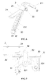
FIG. 7 A schematic view of the collecting of the dust of the invention; -
FIG. 8 A schematic view of the panel of the air conditioner of the invention. - As shown in
FIG.1 , the self-cleaning device of filtering net of the invention which is set in the wall-hanging type air conditioner includes: a filtering net 1 disposed outside of the heat exchanger which includes anupper filtering net 11 and afront filtering net 12, and is used for absorbing the dust of the air passing through the heat exchanger; a dust sweepingassembly 2 with a detachable brush 20 ( shown inFIG. 6 ), which is disposed outside the filtering net 1 and is used for sweeping the dust on the filtering net of the air conditioner; a drive device 3 with adrive motor 31 and a transmission mechanism, which is used for driving the dust sweepingassembly 2 to slide on the filtering net 1 to sweep off the dust; adust box 4 which is used for collecting the dust and is detachably disposed in the air conditioner to clear up the dust in the box; and adust exchanging device 5 which is disposed on the left or right side of the filtering net 1, and is used for transferring the dust swept out by thesweeping assembly 2 into thedust box 4. - In this embodiment, the
dust exchanging device 5 and thedust box 4 are disposed on the left side of the filtering net 1, thedust exchanging device 5 includes two parts which are respectively disposed on the left side of theupper filtering net 11 and the front filteringnet 12, thedust box 4 is located under thedust exchanging device 5 on the left side of thefront filtering net 12; Thedrive motor 31 is disposed on the right side of the filtering net 1. - As shown in
FIG. 6 , the dust sweeping assembly includes abasal body 21 with 'L' in shape and a slide locating device, that the basal body is composed of an upperbasal body 211 and a frontbasal body 212 which are respectively correspondingly located outside theupper filtering net 11 and the front filtering net 12. Thebasal body 21 is holistically covered on the filtering net 1, and is fixedly disposed in the slide way of the upside of theupper filtering net 11 and the downside of the front filteringnet 12 through the slide locating device respectively disposed on the both ends of the basal body. The slide locating device includes asliding wheel 22 that can slide along the slide way and a locatingblock 23 used for preventing the basal body from deviating, which can decrease the vibration of the sliding of the sweeping assembly to reduce the noise. - Wherein, chambers are respectively located in the upper
basal body 211 and the frontbasal body 212 along their length direction. Abrush assembly 20 thrusts into the chambers from the outside of the basal body and is attached with the filtering net inside the basal body to realize best sweeping effects. Turnover covers 24 are provided on thebasal body 21 corresponding to the chambers to prevent thebrush assembly 20 from detaching. The upside of theturnover cover 24 corresponding to the frontbasal body 212 is pin-joined with thebasal body 21, and the downside of theturnover cover 24 corresponding to the upperbasal body 211 is pin-joined with thebasal body 21. Both of the two turnover covers turn up towards the middle of the bend of the 'L' shaped basal body, and theturnover cover 24 is fixed on thebasal body 21 by bolts or buckles. The buckle mechanism (not shown in the FIGs) is non-roundness buttons being usually shape of rectangle or ellipse set on the basal body. An opening matching with the shape of the buttons is disposed on the position of the turnover cover corresponding to the buttons. The buttons passed through the opening are rotated to dislocate the opening and fix the turnover cover after the turnover cover is closed, which makes it easy to change when the brush is frayed. - As shown in
Fig. 2 , thedrive motor 31 is a step motor, , which is located on the right side of the joint of theupper filtering net 11 and the front filteringnet 12 and fixed inside theelectric motor box 311. The transmission mechanism is composed of a drive shaft 32 connected with thedrive motor 31, thewormgear 33 that is freely slidable located on the drive shaft 32 and rotate together with the drive shaft, and the rack 34 meshed with thewormgear 33. Wherein, the drive shaft with the structure of regular polygonal column is parallel with the rack 34 and located at the joint of theupper filtering net 11 and the front filteringnet 12. The rack 34 is smoothly located between the upper filteringnet 11 and the front filteringnet 12, and the drive shaft 32 is located above the rack 34. Thewormgear 33 is pin-jointed inside the bend portion of the 'L' in shape of the basal body 21 (shown asFig.6 ), and both ends of the rack 34 and/or the drive shaft 32 have travel switches( not shown in the figure) which make the step motor to reversely run when the sweeping assembly reaches the designated position, which cooperates with the slide locating device to reduce the driving noise. - In addition, the transmission mechanism is composed of the drive shaft with external thread which is connected with the drive motor, and the internal thread which is located on the basal body and screwed on the external thread, the basal body is slidable located on the screw in parallel with the drive shaft, which has the same principle as the above mentioned drive system (not shown in the figure).
- As shown in
FIG. 4 and FIG. 5 , thedust exchanging device 5 is a rectangular frame in which abrush roll 51 for absorbing the dust is pin-jointed in parallel with the side edge of the filtering net 1, thebrush roll 51 is a circular cylinder or semi-cylinder or elliptical column a reset mechanism 511 set on the brush roll can be made of the spring or tension spring, thedust exchanging device 5 is respectively located in theslots 6 set on the left side of theupper filtering net 11 and the front filtering net 12, and there is a communicateddust passage 7 with downward inclination in the bottom of theslots 6, thedust box slot 8 whose interior is communicated with theslot 6 is located under theslot 6 of the left side of the front filteringnet 12. Thedust box 4 being a box structure with anopening 41 that is communicated with thedust passage 7 is pull-pluggably located in the dust box slot 8.Elastic lugs 50 (shown asFig.4 ) are respectively set on the lateral part of the dust exchanging device and the bottom of the dust box to fix thedust exchanging device 5 and thedust box 4 which are independent each other in the slots and the inner dust box slots to realize the fixing. - The
blocks 52 are pin-jointed at both ends of thebrush roll 51, the blocks can freely rotate to the reverse direction of the filtering net or to the direction of the filtering net to impulse thebrush roll 51 to synchronously rotate, theblocks 52 have thereset mechanism 521, and in the reset state the blocks are oriented to the direction of the hatch of the frame. The block can be reset whenever it rotate to any direction. - The inward
extended baffle 53 with areset mechanism 531 which is parallel with thebrush roll 51 is pin-jointed on the side of thebrush roll 51 near the filtering net 1 in the frame of thedust exchanging device 5, the felt is set on the baffle's side near thebrush roll 51 to realize a second dust exchanging, asoft baffle 54 is aslant set along the tangent outwards on the other side of thebrush roll 51, and is deflected away from the filtering net 1. - The exchanging process of the dust includes: the brush on the duct
sweeping assembly 2 moving the dust on the filtering net 1, thesweeping assembly 2 sliding to thedust exchanging device 5, theblock 52 being pushed to press into the frame by thesweeping assembly 2 when it passes through thedust exchanging device 5, the dust being adsorbed and swept by thebrush roll 51 and thesoft baffle 54 in turn, theblock 52 being reset after passing the sweeping assembly 5 ( shown asFig.7 ), thesweeping assembly 2 driving the blocks on both sides of the dust exchanging device to rotate and pushing the brush roll to rotate when it reversely passing through thedust exchanging device 5, the dust blocked by thebrush roll 51 being put into thedust passage 7 and then into thedust box 4 through adust passage 7, thebrush roll 51 being reset by spring or tension spring after thesweeping assembly 2 slides over thedust exchanging device 5, the residual dust on thebrush roll 51 being cleaned again by thebaffle 53, thebrush roll 51 and thesoft baffle 54 being reset to seal the hatch of the frame to prevent the dust being taken out. - The dust can be stored in the dust box after sweeping each time, which can be cleaned every two to three years according to the operating environment. The invention improves the air-conditioner panel compared with the integral panel of the prior art for the convenience of cleaning the dust in the dust box. In the prior art, the panel must be entirely opened to clean the dust box, which is inconvenient. The present invention adopts a panel which is divided into the upper part and the lower part, the connection relation of the upper fixed panel 9 and the air-conditioner is kept fixed, and the lower panel is the
slide panel 10 which can slide rightward and leftward and cover the outside of thedust box 4. It can be taken out for cleaning only by rightward sliding thepanel 10 for a distance of the dust box in the process of cleaning. The panel can be replaced after cleaning, which is very convenient. - The self-cleaning device of the air conditioner of the invention can clear away the dust on the filtering net in a short time with good dedusting effects, less noise, and simple structure with reliability and durability.
Claims (11)
- A self-cleaning device disposed in the wall-mounted air conditioner, characterized in that the device includes:a filtering net disposed on the outside of a heat exchanger, which includes an upper filtering net and a front filtering net, and is used for absorbing the dust of the air passing through the heat exchanger;a dust sweeping assembly with a detachable brush, which is disposed on the outside of the filtering net and is used for sweeping the dust on the filtering net;a drive device with a drive motor and a transmission mechanism, which is used for driving the dust sweeping assembly to slide on the filtering net to sweep off the dust;a dust box which is used for collecting the dust and is detachably disposed in the air conditioner to clear up the dust in the box;a dust exchanging device which is disposed on the left or right side of the filtering net, and is used for transferring the dust swept out by the sweeping assembly into the dust box.
- The self-cleaning device of filtering net of air conditioner according to Claim 1, characterized in that the dust sweeping assembly includes the basal body with 'L' in shape and a slide locating device, the basal body is composed by an upper basal body and a front basal body which are respectively correspondingly located on the outside of the upper filtering net and the front filtering net, the slide locating device located on both ends of the basal body is respectively located in the slide way of the upside of the upper filtering net and the downside of the front filtering net, the slide locating device includes a sliding wheel that can slide along the slide way and a locating block used for preventing the basal body deviating.
- The self-cleaning device of filtering net of air conditioner according to Claim 1 or 2, characterized in that chambers are respectively located in the upper basal body and the front basal body, a brush assembly thrusts into the chambers from the outside of the basal body, turnover covers are provided on the basal body corresponding to the chambers a to prevent the brush assembly from detaching, and one side of the turnover covers are pin-jointed to the basal body by bolts or buckles.
- The self-cleaning device of filtering net of air conditioner according to Claim 1, characterized in that the drive motor is a step motor, which is located on the left or right side of the joint of the upper filtering net and the front filtering net, the transmission mechanism is composed of a drive shaft connected with the drive motor, a wormgear that is freely slidable located on the drive shaft and rotates together with the drive shaft, and a rack meshed with the wormgear.
- The self-cleaning device of filtering net of air conditioner according to Claim 2 or 4, characterized in that the drive shaft with the structure of regular polygonal column is located at the joint of the upper filtering net and the front filtering net in parallel with the rack and, the rack is smoothly located between the upper filtering net and the front filtering net, the drive shaft is disposed above the rack, the wormgear is pin-jointed inside the bend portion of the 'L'-shape basal body, and both ends of the rack and/or the drive shaft have travel switches
- The self-cleaning device of filtering net of air conditioner according to Claim 1, characterized in that the transmission mechanism is composed of a drive shaft with external thread which is connected with the drive motor, and an internal thread which is located on the basal body and screwed on the external thread, the basal body is slidable located on the screw in parallel with the drive shaft.
- The self-cleaning device of filtering net of air conditioner according to Claim 1, characterized in that the dust exchanging device is a rectangle frame, in which a brush roll for absorbing the dust is pin-jointed in parallel with the side edge of the filtering net, the brush roll is a circular cylinder or semi-cylinder or elliptical column, a reset mechanism set on the brush roll can be made of a spring or a tension spring, the dust exchanging device is respectively located in the slots set on the left or right side of the upper filtering net and front filtering net, and there is a communicated dust passage with downward inclination in the bottom of the slots, a dust box slot whose interior is communicated with the slot is located under the slot set on the side of the front filtering net, the dust box being a box structure with a opening that is communicated with the bottom of the slot is pull-pluggably located in the dust box.
- The self-cleaning device of filtering net of air conditioner according to Claim 7, characterized in that the blocks are pin-jointed at both ends of the brush roll, the blocks can freely rotate to the reverse direction of the filtering net and impulse the brush roll to synchronously rotate to the direction of the filtering net, the blocks have reset mechanism, and in the reset state the blocks are oriented to the direction of the hatch of the frame.
- The self-cleaning device of filtering net of air conditioner according to Claim 7, characterized in that the inward extended baffle with a reset mechanism which is parallel with the brush roll is pin-jointed on the side of the brush roll near the filtering net in the frame of the dust exchanging device, a felt is set on the baffle's side near the brush roll to realize a second dust exchanging, a soft baffle is aslant set along the tangent outwards on the other side of the brush roll, and is deflected away from the filtering net.
- The self-cleaning device of filtering net of air conditioner according to Claim 1 or 7 or 8 or 9, characterized in that the exchanging process of the dust includes: the brush on the duct sweeping assembly moving the dust on the filtering net, the sweeping assembly sliding to the dust exchanging device, the block being pushed to press into the frame by the sweeping assembly when it passes through the dust exchanging device, the dust being adsorbed and swept by the brush and the soft baffle in turn, the block being reset after passing the sweeping assembly, the sweeping assembly driving the blocks on both sides of the dust exchanging device to rotate and pushing the brush roll to rotate when it reversely passing through the dust exchanging device, the dust blocked by the brush roll being put into the dust passage and then into the dust box through a dust passage, the brush roll being reset by spring or tension spring after the sweeping assembly slides over the dust exchanging device, the residual dust on the brush roll being cleaned again by the baffle, the brush roll and the soft baffle being reset to seal the hatch of the frame to prevent the dust from being taken out.
- An air conditioner having the above self-cleaning device of the filtering net includes: a filtering net of an air conditioner disposed outside the heat exchanger, a dust box disposed on the left bottom and right bottom portion of the filtering net, and a panel set on the outside of the filtering net and the dust box, the characteristic is that: the panel includes a upper fixed panel and a lower panel which can slide rightwards or leftwards to conveniently open the dust box.
Applications Claiming Priority (2)
| Application Number | Priority Date | Filing Date | Title |
|---|---|---|---|
| CN200710097812A CN101290152B (en) | 2007-04-18 | 2007-04-18 | Filter self-cleaning device |
| PCT/CN2007/002981 WO2008128402A1 (en) | 2007-04-18 | 2007-10-18 | Self-cleaning device of filtering net and air conditioner having it |
Publications (3)
| Publication Number | Publication Date |
|---|---|
| EP2154442A1 true EP2154442A1 (en) | 2010-02-17 |
| EP2154442A4 EP2154442A4 (en) | 2016-05-25 |
| EP2154442B1 EP2154442B1 (en) | 2018-10-17 |
Family
ID=39875056
Family Applications (1)
| Application Number | Title | Priority Date | Filing Date |
|---|---|---|---|
| EP07816595.8A Active EP2154442B1 (en) | 2007-04-18 | 2007-10-18 | Self-cleaning device of filtering net and air conditioner having it |
Country Status (6)
| Country | Link |
|---|---|
| US (1) | US8241376B2 (en) |
| EP (1) | EP2154442B1 (en) |
| JP (1) | JP2010525286A (en) |
| CN (1) | CN101290152B (en) |
| ES (1) | ES2706019T3 (en) |
| WO (1) | WO2008128402A1 (en) |
Cited By (3)
| Publication number | Priority date | Publication date | Assignee | Title |
|---|---|---|---|---|
| CN107388401A (en) * | 2017-07-12 | 2017-11-24 | 宁波智正伟盈信息科技有限公司 | A kind of air purifier for being easy to clean filter core |
| WO2021227433A1 (en) * | 2020-05-09 | 2021-11-18 | 青岛海尔空调器有限总公司 | Structure for automatically cleaning filtering net of air conditioner, and air conditioner |
| CN118508277A (en) * | 2024-07-18 | 2024-08-16 | 福建艾瑞科电子有限公司 | Intelligent distribution network automation terminal |
Families Citing this family (83)
| Publication number | Priority date | Publication date | Assignee | Title |
|---|---|---|---|---|
| US8303677B2 (en) * | 2007-02-09 | 2012-11-06 | Daikin Industries, Ltd. | Indoor unit of air conditioner |
| KR101173367B1 (en) * | 2007-12-11 | 2012-08-10 | 다이킨 고교 가부시키가이샤 | Indoor unit for air conditioner |
| KR101340528B1 (en) * | 2008-02-04 | 2013-12-11 | 엘지전자 주식회사 | Ceiling type air conditioner |
| WO2010125796A1 (en) * | 2009-04-30 | 2010-11-04 | ダイキン工業株式会社 | Indoor unit for air conditioning device |
| KR101717518B1 (en) * | 2009-09-07 | 2017-03-17 | 엘지전자 주식회사 | Air conditioner |
| WO2012016299A1 (en) * | 2010-08-05 | 2012-02-09 | Ptronik International Pty Ltd | Dust collector control system |
| CN102058347B (en) * | 2010-12-17 | 2012-07-04 | 梁培志 | Household screen window cleaning machine |
| CN102607156A (en) * | 2012-03-19 | 2012-07-25 | 海尔集团公司 | Self-cleaning filtering component of air conditioner and air conditioner indoor unit |
| US20140284027A1 (en) * | 2013-03-22 | 2014-09-25 | Caterpillar Inc. | Heat exchanger cleaning system |
| KR102199380B1 (en) * | 2014-01-17 | 2021-01-06 | 엘지전자 주식회사 | Air conditioner |
| JP6223926B2 (en) * | 2014-08-07 | 2017-11-01 | 三菱電機株式会社 | Filter cleaning device for air conditioner and air conditioner |
| CN105477944B (en) * | 2016-01-21 | 2017-08-29 | 六安同辉智能科技有限公司 | It is a kind of can conveniently treating deposited dust air cleaning unit |
| CN105928071B (en) * | 2016-05-06 | 2019-10-25 | 广东美的制冷设备有限公司 | Air conditioner and cleaning control method thereof |
| CN105953325A (en) * | 2016-05-06 | 2016-09-21 | 广东美的制冷设备有限公司 | Air conditioner and cleaning control method thereof |
| CN106016519A (en) * | 2016-05-06 | 2016-10-12 | 广东美的制冷设备有限公司 | Air conditioner and cleaning control method thereof |
| CN106016521A (en) * | 2016-05-06 | 2016-10-12 | 广东美的制冷设备有限公司 | Air conditioner and self-cleaning control method for air conditioner |
| CN106016520B (en) * | 2016-05-06 | 2019-10-25 | 广东美的制冷设备有限公司 | Air conditioner and cleaning control method thereof |
| CN105972721B (en) * | 2016-05-06 | 2018-12-25 | 广东美的制冷设备有限公司 | Air conditioner and its cleaning control method |
| CN106016475A (en) * | 2016-07-15 | 2016-10-12 | 广东美的制冷设备有限公司 | Indoor air-conditioner |
| CN106091314A (en) * | 2016-08-05 | 2016-11-09 | 珠海格力电器股份有限公司 | Return air subassembly and indoor set panel components |
| CN108120336A (en) * | 2016-11-30 | 2018-06-05 | 国机重工集团常林有限公司 | One kind is from dedusting heat-exchange device |
| CN108224600A (en) * | 2016-12-21 | 2018-06-29 | 苏州昆拓热控系统股份有限公司 | A kind of air conditioner and its compressor assembly method |
| CN107270401B (en) * | 2017-07-01 | 2024-03-19 | 青岛海尔空调器有限总公司 | Wall-mounted air conditioner indoor unit and air conditioner control method |
| CN108105866B (en) * | 2017-12-20 | 2023-04-07 | 青岛海尔空调器有限总公司 | Cleaning device and air conditioner indoor unit with same |
| CN108469880B (en) * | 2018-03-12 | 2020-11-27 | 青岛黄海学院 | A water-cooled circulating dust-removing type computer host chassis structure |
| CN108850151A (en) * | 2018-06-28 | 2018-11-23 | 泉州市顶优优工业设计有限公司 | A kind of paddy mechanical drying device |
| CN109405263A (en) * | 2018-09-30 | 2019-03-01 | 珠海格力电器股份有限公司 | Switchable filter screen structure, air conditioner, filter screen control method, device and medium |
| CN109099520A (en) * | 2018-10-25 | 2018-12-28 | 鞍山奇典生态科技研究所有限公司 | A kind of photocatalyst/absorbent charcoal composite material filtering net air purification reactor |
| CN109140624B (en) * | 2018-11-09 | 2023-09-15 | 珠海格力电器股份有限公司 | Air conditioner filter screen cleaning device, air conditioner and air conditioner filter screen cleaning method |
| CN109289365A (en) * | 2018-11-13 | 2019-02-01 | 徐州赛诺石英有限公司 | A quartz sand dust collector |
| CN111380177A (en) * | 2018-12-29 | 2020-07-07 | 大金工业株式会社 | Air conditioner and cleaning control method thereof |
| CN109546594A (en) * | 2019-01-04 | 2019-03-29 | 杨艳 | Multi-media network cable concentrator with dustproof function and production and preparation method thereof |
| JP7130002B2 (en) * | 2019-01-31 | 2022-09-02 | 広東美的制冷設備有限公司 | Air conditioner indoor unit and air conditioner |
| CN109821318A (en) * | 2019-03-01 | 2019-05-31 | 吴博恩 | Exciter cover automatic cleaning filter air inlet device |
| CN111735231A (en) * | 2019-03-24 | 2020-10-02 | 宁波德业科技股份有限公司 | High-performance corrosion-resistant air conditioner evaporator |
| CN110243087B (en) * | 2019-05-10 | 2020-11-10 | 湖南达道新能源开发有限公司 | Geothermal energy heat exchange device |
| CN111964248A (en) * | 2019-05-20 | 2020-11-20 | 青岛海日高科模型有限公司 | Filter screen, filter screen assembly, air conditioner and filter screen control method |
| CN110486838A (en) * | 2019-08-23 | 2019-11-22 | 青岛海尔空调器有限总公司 | Air conditioner indoor unit and air conditioner |
| CN111013269A (en) * | 2019-12-23 | 2020-04-17 | 范勇 | Utilize unnecessary wind direction of air conditioner vent to shift filter screen structure who gets rid of sweeps |
| CN111151079B (en) * | 2019-12-25 | 2021-09-24 | 安徽美博智能科技有限公司 | A window-mounted air purification device |
| CN111135642B (en) * | 2020-01-07 | 2022-04-22 | 华北电力大学(保定) | Air purifying and filtering mechanism for indoor air conditioner pipeline |
| CN113465038B (en) * | 2020-03-31 | 2026-03-31 | 青岛海尔智能技术研发有限公司 | Structure for self-cleaning air conditioner filters and air conditioners |
| CN113686004B (en) * | 2020-05-19 | 2025-04-22 | 宁波奥克斯电气有限公司 | Cleaning brush driving mechanism and air conditioner |
| CN113686006B (en) * | 2020-05-19 | 2025-04-25 | 宁波奥克斯电气有限公司 | Brush roller cleaning mechanism and air conditioner |
| CN111691706B (en) * | 2020-05-21 | 2025-03-28 | 北京戴纳实验科技股份有限公司 | A modular biosafety buffer corridor |
| CN113899013B (en) * | 2020-07-06 | 2025-01-28 | 宁波奥克斯电气有限公司 | Automatic filter flipping structure and air conditioner |
| CN113345682B (en) * | 2020-09-25 | 2025-06-27 | 怀化市中三源电子有限公司 | A transformer device convenient for heat dissipation |
| CN112628937A (en) * | 2020-12-12 | 2021-04-09 | 安徽美博智能科技有限公司 | Self-cleaning device and self-cleaning method of shared air conditioner |
| CN112902375B (en) * | 2021-01-14 | 2022-07-26 | 山东达洁过滤器有限公司 | Dust cleaning device for air filter |
| CN112933779B (en) * | 2021-04-06 | 2024-08-27 | 华油国新(北京)能源科技有限公司 | Heat supply device of wind-driven compression type heat pump |
| US12474068B2 (en) * | 2021-05-24 | 2025-11-18 | Lg Electronics Inc. | Air-conditioning system |
| US12480667B2 (en) * | 2021-05-24 | 2025-11-25 | Lg Electronics Inc. | Air-conditioning system |
| CN113217069B (en) * | 2021-06-15 | 2023-12-01 | 云南滇东雨汪能源有限公司 | Ventilation device for preventing coal mine gas from exceeding limit |
| CN113617138B (en) * | 2021-09-02 | 2022-08-02 | 北京众鑫兴业大气污染治理有限公司 | Self-cleaning type waste gas purification device |
| CN113654166A (en) * | 2021-10-20 | 2021-11-16 | 南通华信中央空调有限公司 | Air conditioner filter screen with clean warning function |
| CN114275402B (en) * | 2021-11-22 | 2022-10-28 | 浙江微盾环保科技股份有限公司 | Water circulation device for medical waste treatment |
| CN114909763B (en) * | 2022-05-23 | 2024-06-11 | 中国建筑科学研究院有限公司 | An intelligent air purification device for biotechnology |
| CN114992718A (en) * | 2022-05-24 | 2022-09-02 | 青岛海信日立空调系统有限公司 | Indoor unit and air conditioning system |
| CN114811949B (en) * | 2022-05-25 | 2023-05-16 | 江西中聚宏新材料科技有限公司 | High-performance energy-saving air heat pump device |
| CN114963339B (en) * | 2022-05-31 | 2025-11-18 | 海信(广东)空调有限公司 | An air conditioner indoor unit |
| CN115226338B (en) * | 2022-05-31 | 2026-04-07 | 江西百盈高新技术股份有限公司 | A vehicle-mounted inverter with dustproof function |
| CN115144523B (en) * | 2022-06-16 | 2023-05-16 | 苏州工业园区泰智测控技术有限公司 | Wireless interconnection emission data remote transmission composite gas detector |
| CN115264624A (en) * | 2022-08-04 | 2022-11-01 | 珠海格力节能环保制冷技术研究中心有限公司 | Air conditioner indoor unit, air conditioner and control method of air conditioner |
| CN115451754B (en) * | 2022-08-10 | 2025-04-11 | 裕利年电子南通有限公司 | A method and device for removing dust from a condenser inside an air conditioner box |
| CN115399576B (en) * | 2022-09-21 | 2025-06-27 | 江西团团圆家具有限公司 | Automatic cleaning shoe cabinet |
| CN115950002A (en) * | 2022-12-30 | 2023-04-11 | 海信(广东)空调有限公司 | Indoor machine of air conditioner |
| CN116241976B (en) * | 2023-03-24 | 2023-08-25 | 兴化市纪宇塑业有限公司 | A filter device for an air-conditioning outlet |
| CN116558312B (en) * | 2023-05-26 | 2026-04-14 | 南京正领汽车部件有限公司 | Aluminum ingot smelting system for producing hydrogen energy end plate |
| CN117006576B (en) * | 2023-07-14 | 2026-04-07 | 浙江每刻爱尔空气净化科技有限公司 | A micro-electrostatic coupling negative ion purification and disinfection device |
| CN117073179B (en) * | 2023-08-16 | 2024-03-15 | 广州雪源净化工程有限公司 | Purifying control method for room air conditioner for cleaning food industry |
| CN117073089B (en) * | 2023-08-16 | 2024-06-18 | 江苏诺亚净化科技有限公司 | A local ventilation purification treatment device for clean rooms |
| CN117190331A (en) * | 2023-08-17 | 2023-12-08 | 中国通信建设集团有限公司河南省通信服务分公司 | An anti-blocking device for an air conditioner outdoor unit |
| CN116997116A (en) * | 2023-08-22 | 2023-11-03 | 上海勘测设计研究院有限公司 | An energy storage bin that automatically filters impurities |
| CN117295303A (en) * | 2023-09-26 | 2023-12-26 | 深圳市硕洲电子有限公司 | SMT backplate encapsulation box sealed from dust exhaust |
| CN119983397B (en) * | 2023-11-01 | 2025-12-09 | 宁波奥克斯电气有限公司 | Air conditioner |
| CN117205687B (en) * | 2023-11-08 | 2024-04-19 | 江苏迎凯涂装设备有限公司 | But dust collecting equipment of quick assembly disassembly clearance |
| CN117205646B (en) * | 2023-11-08 | 2024-01-26 | 烟台金丝猴食品科技有限公司 | Syrup filter |
| CN117739422B (en) * | 2023-12-20 | 2024-09-13 | 江苏赖氏环保科技有限公司 | Detachable purification structure suitable for evaporative environment-friendly air conditioner |
| CN117628598B (en) * | 2024-01-23 | 2024-04-02 | 中科圣杰(深圳)科技集团有限公司 | Clean canopy supply-air outlet |
| CN118328491B (en) * | 2024-05-17 | 2024-10-22 | 武汉庚泰净化装饰工程有限公司 | Indoor ventilation and air purification circulation system |
| CN118980126B (en) * | 2024-08-23 | 2025-09-19 | 上海麟祥环保股份有限公司 | Central air conditioning new trend system economizer |
| CN119300288A (en) * | 2024-12-10 | 2025-01-10 | 衢州三源汇能电子有限公司 | A mobile voltage regulator |
| CN119436521A (en) * | 2024-12-10 | 2025-02-14 | 布鲁奇维尔通风设备启东有限公司 | A fan duct with a self-cleaning structure |
Family Cites Families (33)
| Publication number | Priority date | Publication date | Assignee | Title |
|---|---|---|---|---|
| US3221479A (en) * | 1961-07-10 | 1965-12-07 | Rockwell Standard Co | Lint arrester |
| JPS5014465B1 (en) * | 1967-07-17 | 1975-05-28 | ||
| JPS52128740A (en) * | 1976-04-19 | 1977-10-28 | Daishiyou Sangiyou Kk | Toothbrush and method of making toothbrush |
| US5215639A (en) * | 1984-10-09 | 1993-06-01 | Genus, Inc. | Composite sputtering target structures and process for producing such structures |
| US4885075A (en) * | 1987-01-27 | 1989-12-05 | Machine Technology, Inc. | Cooling device for a sputter target and source |
| DE3912381A1 (en) * | 1988-04-15 | 1989-10-26 | Sharp Kk | SENSOR UNIT |
| JPH0313570A (en) * | 1989-06-09 | 1991-01-22 | Mitsubishi Electric Corp | Device for producing semiconductor and target for the device |
| JPH0433916U (en) * | 1990-07-11 | 1992-03-19 | ||
| US5693203A (en) * | 1992-09-29 | 1997-12-02 | Japan Energy Corporation | Sputtering target assembly having solid-phase bonded interface |
| US5836506A (en) * | 1995-04-21 | 1998-11-17 | Sony Corporation | Sputter target/backing plate assembly and method of making same |
| US6274015B1 (en) * | 1996-12-13 | 2001-08-14 | Honeywell International, Inc. | Diffusion bonded sputtering target assembly with precipitation hardened backing plate and method of making same |
| US6071389A (en) * | 1998-08-21 | 2000-06-06 | Tosoh Smd, Inc. | Diffusion bonded sputter target assembly and method of making |
| JP4804607B2 (en) * | 1999-12-14 | 2011-11-02 | パナソニック株式会社 | Dust remover |
| US6620296B2 (en) * | 2000-07-17 | 2003-09-16 | Applied Materials, Inc. | Target sidewall design to reduce particle generation during magnetron sputtering |
| US20030178301A1 (en) * | 2001-12-21 | 2003-09-25 | Lynn David Mark | Planar magnetron targets having target material affixed to non-planar backing plates |
| JP4110375B2 (en) * | 2002-06-27 | 2008-07-02 | 株式会社富士通ゼネラル | Air conditioner |
| JP4182328B2 (en) | 2002-07-12 | 2008-11-19 | 株式会社富士通ゼネラル | Air conditioner |
| KR101086607B1 (en) * | 2003-03-04 | 2011-11-23 | 파나소닉 주식회사 | Air conditioner with indoor unit with automatic cleaning function of air filter |
| CN100385175C (en) | 2003-03-11 | 2008-04-30 | 松下电器产业株式会社 | Air Conditioner with Indoor Unit with Air Filter Automatic Cleaning Function |
| JP4107119B2 (en) * | 2003-03-24 | 2008-06-25 | 松下電器産業株式会社 | Air conditioner filter device |
| JP4340850B2 (en) * | 2003-03-28 | 2009-10-07 | 株式会社富士通ゼネラル | Air conditioner |
| KR101065965B1 (en) | 2003-08-18 | 2011-09-19 | 파나소닉 주식회사 | Air conditioner with indoor unit with automatic cleaning of the air filter |
| US7544223B2 (en) * | 2004-09-02 | 2009-06-09 | Fujitsu General Limited | Air conditioner |
| CN100565028C (en) * | 2004-09-03 | 2009-12-02 | 富士通将军股份有限公司 | air conditioner |
| JP4435667B2 (en) * | 2004-11-09 | 2010-03-24 | パナソニック株式会社 | Air conditioner with indoor unit with automatic air filter cleaning function |
| JP4418427B2 (en) * | 2005-07-04 | 2010-02-17 | 三菱重工業株式会社 | Indoor unit and air conditioner |
| US8038517B2 (en) * | 2005-09-13 | 2011-10-18 | Fujitsu General Limited | Air conditioner and method for assembling the same |
| JP4849207B2 (en) | 2005-09-13 | 2012-01-11 | 株式会社富士通ゼネラル | Air conditioner |
| JP4701978B2 (en) * | 2005-10-06 | 2011-06-15 | パナソニック株式会社 | Air conditioner filter device |
| JP2007240114A (en) * | 2006-03-10 | 2007-09-20 | Kowa Co Ltd | Air conditioner cleaning device and air conditioner |
| CN2886399Y (en) * | 2006-03-13 | 2007-04-04 | 广东美的电器股份有限公司 | Automatic dust collector for air conditioner filter mesh |
| JP4287873B2 (en) * | 2006-08-31 | 2009-07-01 | 日立アプライアンス株式会社 | Air conditioner |
| JP2008116122A (en) * | 2006-11-06 | 2008-05-22 | Hitachi Appliances Inc | Air conditioner |
-
2007
- 2007-04-18 CN CN200710097812A patent/CN101290152B/en active Active
- 2007-10-18 ES ES07816595T patent/ES2706019T3/en active Active
- 2007-10-18 JP JP2010503334A patent/JP2010525286A/en active Pending
- 2007-10-18 US US12/596,319 patent/US8241376B2/en not_active Expired - Fee Related
- 2007-10-18 EP EP07816595.8A patent/EP2154442B1/en active Active
- 2007-10-18 WO PCT/CN2007/002981 patent/WO2008128402A1/en not_active Ceased
Non-Patent Citations (1)
| Title |
|---|
| See references of WO2008128402A1 * |
Cited By (3)
| Publication number | Priority date | Publication date | Assignee | Title |
|---|---|---|---|---|
| CN107388401A (en) * | 2017-07-12 | 2017-11-24 | 宁波智正伟盈信息科技有限公司 | A kind of air purifier for being easy to clean filter core |
| WO2021227433A1 (en) * | 2020-05-09 | 2021-11-18 | 青岛海尔空调器有限总公司 | Structure for automatically cleaning filtering net of air conditioner, and air conditioner |
| CN118508277A (en) * | 2024-07-18 | 2024-08-16 | 福建艾瑞科电子有限公司 | Intelligent distribution network automation terminal |
Also Published As
| Publication number | Publication date |
|---|---|
| US8241376B2 (en) | 2012-08-14 |
| EP2154442A4 (en) | 2016-05-25 |
| US20100116463A1 (en) | 2010-05-13 |
| WO2008128402A1 (en) | 2008-10-30 |
| CN101290152B (en) | 2010-05-26 |
| ES2706019T3 (en) | 2019-03-27 |
| EP2154442B1 (en) | 2018-10-17 |
| JP2010525286A (en) | 2010-07-22 |
| CN101290152A (en) | 2008-10-22 |
Similar Documents
| Publication | Publication Date | Title |
|---|---|---|
| US8241376B2 (en) | Self-cleaning device of filtering net and air conditioner having it | |
| AU2006213929B2 (en) | Air conditioner and method for assembling the same | |
| CN101290151B (en) | Air conditioning filter self-cleaning device | |
| CN106705245B (en) | Air conditioner with purification function | |
| CN102203516B (en) | Filters and air adjusting device with same | |
| CN103062880B (en) | Air conditioner | |
| CN208567076U (en) | Dust case assembly, air conditioner indoor unit and air conditioner | |
| CN101278159A (en) | Air conditioning device and filter used therein | |
| CN1932396B (en) | air conditioner | |
| CN215876675U (en) | Ventilation filter device of environment-friendly air purification equipment | |
| CN113685911A (en) | Self-cleaning device and air conditioner | |
| CN114060943A (en) | Air conditioner | |
| CN216620045U (en) | Air conditioner | |
| CN217482969U (en) | Air inlet closing device and air conditioner indoor unit | |
| CN114754457B (en) | Dust collector and have its air conditioning indoor set | |
| CN213019915U (en) | Air conditioner and its casing | |
| CN102384572B (en) | Conditioner and the filter used wherein | |
| CN218296188U (en) | A dustproof subassembly and air conditioner for air conditioner | |
| CN210511986U (en) | Spiral cover assembly and air purifier | |
| JP4119448B2 (en) | Air conditioner | |
| CN211119664U (en) | Air conditioner | |
| KR20090022092A (en) | Air conditioner | |
| CN114738984A (en) | Air Inlet Closure Device and Air Conditioner Indoor Unit | |
| CN113680759B (en) | Air duct cleaning device and air conditioner | |
| JP5216289B2 (en) | Air conditioner |
Legal Events
| Date | Code | Title | Description |
|---|---|---|---|
| PUAI | Public reference made under article 153(3) epc to a published international application that has entered the european phase |
Free format text: ORIGINAL CODE: 0009012 |
|
| 17P | Request for examination filed |
Effective date: 20091118 |
|
| AK | Designated contracting states |
Kind code of ref document: A1 Designated state(s): AT BE BG CH CY CZ DE DK EE ES FI FR GB GR HU IE IS IT LI LT LU LV MC MT NL PL PT RO SE SI SK TR |
|
| AX | Request for extension of the european patent |
Extension state: AL BA HR MK RS |
|
| DAX | Request for extension of the european patent (deleted) | ||
| RA4 | Supplementary search report drawn up and despatched (corrected) |
Effective date: 20160422 |
|
| RIC1 | Information provided on ipc code assigned before grant |
Ipc: F24F 1/00 20110101ALI20160418BHEP Ipc: F24F 3/16 20060101ALI20160418BHEP Ipc: F24F 13/28 20060101AFI20160418BHEP |
|
| GRAP | Despatch of communication of intention to grant a patent |
Free format text: ORIGINAL CODE: EPIDOSNIGR1 |
|
| STAA | Information on the status of an ep patent application or granted ep patent |
Free format text: STATUS: GRANT OF PATENT IS INTENDED |
|
| INTG | Intention to grant announced |
Effective date: 20180508 |
|
| GRAS | Grant fee paid |
Free format text: ORIGINAL CODE: EPIDOSNIGR3 |
|
| GRAA | (expected) grant |
Free format text: ORIGINAL CODE: 0009210 |
|
| STAA | Information on the status of an ep patent application or granted ep patent |
Free format text: STATUS: THE PATENT HAS BEEN GRANTED |
|
| AK | Designated contracting states |
Kind code of ref document: B1 Designated state(s): AT BE BG CH CY CZ DE DK EE ES FI FR GB GR HU IE IS IT LI LT LU LV MC MT NL PL PT RO SE SI SK TR |
|
| REG | Reference to a national code |
Ref country code: GB Ref legal event code: FG4D |
|
| REG | Reference to a national code |
Ref country code: CH Ref legal event code: EP |
|
| REG | Reference to a national code |
Ref country code: IE Ref legal event code: FG4D |
|
| REG | Reference to a national code |
Ref country code: DE Ref legal event code: R096 Ref document number: 602007056538 Country of ref document: DE Ref country code: AT Ref legal event code: REF Ref document number: 1054527 Country of ref document: AT Kind code of ref document: T Effective date: 20181115 |
|
| REG | Reference to a national code |
Ref country code: NL Ref legal event code: MP Effective date: 20181017 |
|
| REG | Reference to a national code |
Ref country code: LT Ref legal event code: MG4D |
|
| REG | Reference to a national code |
Ref country code: AT Ref legal event code: MK05 Ref document number: 1054527 Country of ref document: AT Kind code of ref document: T Effective date: 20181017 |
|
| REG | Reference to a national code |
Ref country code: ES Ref legal event code: FG2A Ref document number: 2706019 Country of ref document: ES Kind code of ref document: T3 Effective date: 20190327 |
|
| PG25 | Lapsed in a contracting state [announced via postgrant information from national office to epo] |
Ref country code: NL Free format text: LAPSE BECAUSE OF FAILURE TO SUBMIT A TRANSLATION OF THE DESCRIPTION OR TO PAY THE FEE WITHIN THE PRESCRIBED TIME-LIMIT Effective date: 20181017 |
|
| PG25 | Lapsed in a contracting state [announced via postgrant information from national office to epo] |
Ref country code: IS Free format text: LAPSE BECAUSE OF FAILURE TO SUBMIT A TRANSLATION OF THE DESCRIPTION OR TO PAY THE FEE WITHIN THE PRESCRIBED TIME-LIMIT Effective date: 20190217 Ref country code: LT Free format text: LAPSE BECAUSE OF FAILURE TO SUBMIT A TRANSLATION OF THE DESCRIPTION OR TO PAY THE FEE WITHIN THE PRESCRIBED TIME-LIMIT Effective date: 20181017 Ref country code: AT Free format text: LAPSE BECAUSE OF FAILURE TO SUBMIT A TRANSLATION OF THE DESCRIPTION OR TO PAY THE FEE WITHIN THE PRESCRIBED TIME-LIMIT Effective date: 20181017 Ref country code: PL Free format text: LAPSE BECAUSE OF FAILURE TO SUBMIT A TRANSLATION OF THE DESCRIPTION OR TO PAY THE FEE WITHIN THE PRESCRIBED TIME-LIMIT Effective date: 20181017 Ref country code: BG Free format text: LAPSE BECAUSE OF FAILURE TO SUBMIT A TRANSLATION OF THE DESCRIPTION OR TO PAY THE FEE WITHIN THE PRESCRIBED TIME-LIMIT Effective date: 20190117 Ref country code: FI Free format text: LAPSE BECAUSE OF FAILURE TO SUBMIT A TRANSLATION OF THE DESCRIPTION OR TO PAY THE FEE WITHIN THE PRESCRIBED TIME-LIMIT Effective date: 20181017 Ref country code: LV Free format text: LAPSE BECAUSE OF FAILURE TO SUBMIT A TRANSLATION OF THE DESCRIPTION OR TO PAY THE FEE WITHIN THE PRESCRIBED TIME-LIMIT Effective date: 20181017 |
|
| PG25 | Lapsed in a contracting state [announced via postgrant information from national office to epo] |
Ref country code: SE Free format text: LAPSE BECAUSE OF FAILURE TO SUBMIT A TRANSLATION OF THE DESCRIPTION OR TO PAY THE FEE WITHIN THE PRESCRIBED TIME-LIMIT Effective date: 20181017 Ref country code: PT Free format text: LAPSE BECAUSE OF FAILURE TO SUBMIT A TRANSLATION OF THE DESCRIPTION OR TO PAY THE FEE WITHIN THE PRESCRIBED TIME-LIMIT Effective date: 20190217 Ref country code: GR Free format text: LAPSE BECAUSE OF FAILURE TO SUBMIT A TRANSLATION OF THE DESCRIPTION OR TO PAY THE FEE WITHIN THE PRESCRIBED TIME-LIMIT Effective date: 20190118 |
|
| REG | Reference to a national code |
Ref country code: CH Ref legal event code: PL |
|
| REG | Reference to a national code |
Ref country code: BE Ref legal event code: MM Effective date: 20181031 |
|
| PG25 | Lapsed in a contracting state [announced via postgrant information from national office to epo] |
Ref country code: LU Free format text: LAPSE BECAUSE OF NON-PAYMENT OF DUE FEES Effective date: 20181018 |
|
| REG | Reference to a national code |
Ref country code: DE Ref legal event code: R097 Ref document number: 602007056538 Country of ref document: DE |
|
| REG | Reference to a national code |
Ref country code: IE Ref legal event code: MM4A |
|
| PG25 | Lapsed in a contracting state [announced via postgrant information from national office to epo] |
Ref country code: DK Free format text: LAPSE BECAUSE OF FAILURE TO SUBMIT A TRANSLATION OF THE DESCRIPTION OR TO PAY THE FEE WITHIN THE PRESCRIBED TIME-LIMIT Effective date: 20181017 Ref country code: CZ Free format text: LAPSE BECAUSE OF FAILURE TO SUBMIT A TRANSLATION OF THE DESCRIPTION OR TO PAY THE FEE WITHIN THE PRESCRIBED TIME-LIMIT Effective date: 20181017 |
|
| PLBE | No opposition filed within time limit |
Free format text: ORIGINAL CODE: 0009261 |
|
| STAA | Information on the status of an ep patent application or granted ep patent |
Free format text: STATUS: NO OPPOSITION FILED WITHIN TIME LIMIT |
|
| PG25 | Lapsed in a contracting state [announced via postgrant information from national office to epo] |
Ref country code: EE Free format text: LAPSE BECAUSE OF FAILURE TO SUBMIT A TRANSLATION OF THE DESCRIPTION OR TO PAY THE FEE WITHIN THE PRESCRIBED TIME-LIMIT Effective date: 20181017 Ref country code: RO Free format text: LAPSE BECAUSE OF FAILURE TO SUBMIT A TRANSLATION OF THE DESCRIPTION OR TO PAY THE FEE WITHIN THE PRESCRIBED TIME-LIMIT Effective date: 20181017 Ref country code: BE Free format text: LAPSE BECAUSE OF NON-PAYMENT OF DUE FEES Effective date: 20181031 Ref country code: LI Free format text: LAPSE BECAUSE OF NON-PAYMENT OF DUE FEES Effective date: 20181031 Ref country code: SK Free format text: LAPSE BECAUSE OF FAILURE TO SUBMIT A TRANSLATION OF THE DESCRIPTION OR TO PAY THE FEE WITHIN THE PRESCRIBED TIME-LIMIT Effective date: 20181017 Ref country code: CH Free format text: LAPSE BECAUSE OF NON-PAYMENT OF DUE FEES Effective date: 20181031 Ref country code: MC Free format text: LAPSE BECAUSE OF FAILURE TO SUBMIT A TRANSLATION OF THE DESCRIPTION OR TO PAY THE FEE WITHIN THE PRESCRIBED TIME-LIMIT Effective date: 20181017 |
|
| 26N | No opposition filed |
Effective date: 20190718 |
|
| PG25 | Lapsed in a contracting state [announced via postgrant information from national office to epo] |
Ref country code: IE Free format text: LAPSE BECAUSE OF NON-PAYMENT OF DUE FEES Effective date: 20181018 Ref country code: SI Free format text: LAPSE BECAUSE OF FAILURE TO SUBMIT A TRANSLATION OF THE DESCRIPTION OR TO PAY THE FEE WITHIN THE PRESCRIBED TIME-LIMIT Effective date: 20181017 |
|
| PG25 | Lapsed in a contracting state [announced via postgrant information from national office to epo] |
Ref country code: MT Free format text: LAPSE BECAUSE OF NON-PAYMENT OF DUE FEES Effective date: 20181018 |
|
| PG25 | Lapsed in a contracting state [announced via postgrant information from national office to epo] |
Ref country code: TR Free format text: LAPSE BECAUSE OF FAILURE TO SUBMIT A TRANSLATION OF THE DESCRIPTION OR TO PAY THE FEE WITHIN THE PRESCRIBED TIME-LIMIT Effective date: 20181017 |
|
| PG25 | Lapsed in a contracting state [announced via postgrant information from national office to epo] |
Ref country code: CY Free format text: LAPSE BECAUSE OF FAILURE TO SUBMIT A TRANSLATION OF THE DESCRIPTION OR TO PAY THE FEE WITHIN THE PRESCRIBED TIME-LIMIT Effective date: 20181017 Ref country code: HU Free format text: LAPSE BECAUSE OF FAILURE TO SUBMIT A TRANSLATION OF THE DESCRIPTION OR TO PAY THE FEE WITHIN THE PRESCRIBED TIME-LIMIT; INVALID AB INITIO Effective date: 20071018 |
|
| PGFP | Annual fee paid to national office [announced via postgrant information from national office to epo] |
Ref country code: DE Payment date: 20251015 Year of fee payment: 19 |
|
| PGFP | Annual fee paid to national office [announced via postgrant information from national office to epo] |
Ref country code: GB Payment date: 20251023 Year of fee payment: 19 |
|
| PGFP | Annual fee paid to national office [announced via postgrant information from national office to epo] |
Ref country code: IT Payment date: 20251007 Year of fee payment: 19 |
|
| PGFP | Annual fee paid to national office [announced via postgrant information from national office to epo] |
Ref country code: FR Payment date: 20251027 Year of fee payment: 19 |
|
| PGFP | Annual fee paid to national office [announced via postgrant information from national office to epo] |
Ref country code: ES Payment date: 20251110 Year of fee payment: 19 |