JP4435667B2 - Air conditioner with indoor unit with automatic air filter cleaning function - Google Patents
Air conditioner with indoor unit with automatic air filter cleaning function Download PDFInfo
- Publication number
- JP4435667B2 JP4435667B2 JP2004325364A JP2004325364A JP4435667B2 JP 4435667 B2 JP4435667 B2 JP 4435667B2 JP 2004325364 A JP2004325364 A JP 2004325364A JP 2004325364 A JP2004325364 A JP 2004325364A JP 4435667 B2 JP4435667 B2 JP 4435667B2
- Authority
- JP
- Japan
- Prior art keywords
- cleaning member
- air
- air conditioner
- filter
- air filter
- Prior art date
- Legal status (The legal status is an assumption and is not a legal conclusion. Google has not performed a legal analysis and makes no representation as to the accuracy of the status listed.)
- Active
Links
- 238000004140 cleaning Methods 0.000 title claims description 44
- 239000000428 dust Substances 0.000 claims description 32
- 230000007246 mechanism Effects 0.000 claims description 24
- 230000007257 malfunction Effects 0.000 claims description 15
- 238000001514 detection method Methods 0.000 claims description 8
- 238000011144 upstream manufacturing Methods 0.000 claims description 8
- 238000004891 communication Methods 0.000 claims description 2
- 238000003780 insertion Methods 0.000 description 7
- 230000037431 insertion Effects 0.000 description 7
- 238000004804 winding Methods 0.000 description 5
- 238000000034 method Methods 0.000 description 4
- 230000008569 process Effects 0.000 description 4
- 230000005540 biological transmission Effects 0.000 description 3
- 230000009467 reduction Effects 0.000 description 3
- 238000007664 blowing Methods 0.000 description 2
- 230000004308 accommodation Effects 0.000 description 1
- 238000005452 bending Methods 0.000 description 1
- 230000008878 coupling Effects 0.000 description 1
- 238000010168 coupling process Methods 0.000 description 1
- 238000005859 coupling reaction Methods 0.000 description 1
- 238000007667 floating Methods 0.000 description 1
- 239000002184 metal Substances 0.000 description 1
- 230000004048 modification Effects 0.000 description 1
- 238000012986 modification Methods 0.000 description 1
- 230000002265 prevention Effects 0.000 description 1
Images


Description
本発明は、室内ユニットの空気吸込口に設けられたエアフィルタを自動的に清掃する機能を備えた空気調和機に関する。 The present invention relates to an air conditioner having a function of automatically cleaning an air filter provided in an air suction port of an indoor unit.
従来の空気調和機の室内ユニットにおいては、本体内部への塵埃の侵入を防止するためのエアフィルタが熱交換器の前面に設けられており、エアフィルタは付着した塵埃を除去できるようにフィルタ枠に着脱自在に取り付けられている。 In a conventional indoor unit of an air conditioner, an air filter for preventing dust from entering the inside of the main body is provided on the front surface of the heat exchanger, and the air filter can remove the adhering dust. Removably attached to.
最近では、エアフィルタをフィルタ枠から取り外すことなくエアフィルタに付着した塵埃を自動的に除去できるようにした空気調和機も提案されている(例えば、特許文献1参照。)。 Recently, an air conditioner has also been proposed in which dust attached to an air filter can be automatically removed without removing the air filter from the filter frame (see, for example, Patent Document 1).
この空気調和機にあっては、エアフィルタを清掃するための清掃装置が、エアフィルタを回動させる回動手段と、エアフィルタ上の塵埃を除去する塵埃除去手段と、塵埃を収納する塵埃収納部とで構成され、塵埃除去手段は、エアフィルタ上を移動自在に取り付けられた塵埃吸引部と、本体内に設けられた吸引ファン部と、塵埃吸引部と吸引ファン部とを連結する吸引ダクト部とで構成されている。また、エアフィルタ上には固定レールが設けられ、固定レールの一端あるいは本体の一部には巻き取りモータが設けられるとともに、巻き取りモータと塵埃吸引部とは巻き取り式の薄板ばねで連結されており、巻き取りモータを駆動することにより薄板ばねが巻き取られ、塵埃吸引部が移動するように構成されている。 In this air conditioner, the cleaning device for cleaning the air filter includes a rotating means for rotating the air filter, a dust removing means for removing dust on the air filter, and a dust container for storing dust. The dust removing means includes a dust suction part movably mounted on the air filter, a suction fan part provided in the main body, and a suction duct connecting the dust suction part and the suction fan part. It consists of parts. In addition, a fixed rail is provided on the air filter, and a winding motor is provided at one end of the fixed rail or a part of the main body, and the winding motor and the dust suction portion are connected by a winding thin plate spring. The thin plate spring is wound up by driving the winding motor, and the dust suction part moves.
特許文献1に記載の空気調和機においては、巻き取りモータによる塵埃吸引部を駆動して塵埃を吸引する構成ではあるが、その駆動機構が十分開示されているとは言い難く、簡素な構成で信頼性の高い駆動機構が求められていた。
The air conditioner described in
本発明は、従来技術の有するこのような問題点に鑑みてなされたものであり、簡素な構成で塵埃吸引部を確実に駆動できる信頼性の高い駆動機構を有する室内ユニットを備えた空気調和機を提供することを目的としている。 The present invention has been made in view of such problems of the prior art, and is an air conditioner including an indoor unit having a highly reliable drive mechanism that can reliably drive a dust suction unit with a simple configuration. The purpose is to provide.
上記目的を達成するために、本発明のうちで請求項1に記載の発明は、熱交換器と該熱交換器で熱交換された空気を室内に吹き出すファンとを本体に収容した室内ユニットを有する空気調和機であって、前記熱交換器の上流側の前記本体にフィルタ枠を介して取り付けられたエアフィルタと、該エアフィルタに対向する吸入口を有しエアフィルタに付着した塵埃を吸入するための摺動自在の吸引ノズルと、該吸引ノズルを駆動機構を介して駆動する駆動源と、前記吸引ノズルに連通し空気と共に塵埃を吸引排気する排気装置と、該排気装置と前記吸引ノズルとを連通する連通手段とを備え、前記駆動機構を、前記駆動源に連結された駆動軸と、前記駆動軸に摺動自在に取り付けられ前記吸引ノズルと一体的に摺動するウォームギヤと、該ウォームギヤと噛み合うラックとにより構成するとともに、前記吸引ノズルが所定の方向に摺動するベルトを備え、該ベルトに所定長さの吸引孔を形成し、空気調和機の停止中に、前記吸引ノズルを1方向に摺動させて前記エアフィルタの一部を清掃し、さらに前記吸引孔を前記1方向と直交する方向に前記吸引孔の長さだけ移動させた後、前記吸引ノズルを前記1方向の逆方向に摺動させて前記エアフィルタの別の一部を清掃し、前記吸引ノズルの作動不良を検出するノズル作動不良検出手段を前記フィルタ枠に取り付けたことを特徴とする。
In order to achieve the above object, the invention according to
また、請求項2に記載の発明は、前記ノズル作動不良検出手段が前記フィルタ枠に取り付けられたリミットスイッチであり、所定時間内に該リミットスイッチに入力がなかった場合に前記吸引ノズルが所定の位置に到達していないと判断するようにしたことを特徴とする。
According to a second aspect of the present invention, the nozzle malfunction detection means is a limit switch attached to the filter frame, and the suction nozzle is predetermined when there is no input to the limit switch within a predetermined time. It is characterized in that it is determined that the position has not been reached .
また、請求項3に記載の発明は、熱交換器と該熱交換器で熱交換された空気を室内に吹き出すファンとを本体に収容した室内ユニットを有する空気調和機であって、前記熱交換器の上流側の前記本体にフィルタ枠を介して取り付けられたエアフィルタと、該エアフィルタに付着した塵埃を除去するための摺動自在の清掃用部材と、該清掃用部材を駆動機構を介して駆動する駆動源とを備え、前記駆動機構は、前記駆動源に連結された駆動軸と、前記駆動軸に摺動自在に取り付けられ前記清掃用部材と一体的に摺動するウォームギヤと、該ウォームギヤと噛み合うラックとにより構成されるとともに、空気調和機の停止中に、前記清掃用部材を1方向に摺動させて前記エアフィルタの一部を清掃し、さらに前記清掃用部材を前記1方向の逆方向に摺動させて前記エアフィルタの別の一部を清掃し、前記清掃用部材の作動不良を検出する清掃用部材作動不良検出手段を前記フィルタ枠に取り付けたことを特徴とする。
The invention according to
また、請求項4に記載の発明は、熱交換器と該熱交換器で熱交換された空気を室内に吹き出すファンとを本体に収容した室内ユニットを有する空気調和機であって、前記熱交換器の上流側の前記本体にフィルタ枠を介して取り付けられたエアフィルタと、該エアフィルタに付着した塵埃を除去するための清掃用部材と、該清掃用部材を駆動機構を介して駆動する駆動源とを備え、前記駆動機構は、前記駆動源に連結され雄ねじが形成された駆動軸と、前記清掃用部材に取り付けられ前記雄ねじと螺合する雌ねじとにより構成されるとともに、空気調和機の停止中に、前記清掃用部材を1方向に摺動させて前記エアフィルタの一部を清掃し、さらに前記清掃用部材を前記1方向の逆方向に摺動させて前記エアフィルタの別の一部を清掃し、前記清掃用部材の作動不良を検出する清掃用部材作動不良検出手段を前記フィルタ枠に取り付けたことを特徴とする。
The invention according to
さらに、請求項5に記載の発明は、前記清掃用部材作動不良検出手段が前記フィルタ枠に取り付けられたリミットスイッチであり、所定時間内に該リミットスイッチに入力がなかった場合に前記清掃用部材が所定の位置に到達していないと判断するようにしたことを特徴とする。
Further, the invention according to claim 5 is that the cleaning member operation failure detecting means is a limit switch attached to the filter frame, and the cleaning member is operated when there is no input to the limit switch within a predetermined time. Is determined not to reach a predetermined position .
また、請求項6に記載の発明は、前記清掃用部材に設けられ前記エアフィルタに付着した塵埃を除去するブラシと、前記フィルタ枠の左右のうちのいずれかの片側に形成され前記エアフィルタの清掃時以外に前記清掃用部材を保持する保持部とをさらに備えたことを特徴とする。
According to a sixth aspect of the present invention, there is provided a brush for removing dust adhering to the air filter provided on the cleaning member and one of the left and right sides of the filter frame. And a holding portion for holding the cleaning member other than during cleaning .
本発明によれば、吸引ノズルを駆動する駆動機構を、駆動源に連結された駆動軸と、駆動軸に摺動自在に取り付けられ吸引ノズルと一体的に摺動するウォームギヤと、このウォームギヤと噛み合うラックとにより、あるいは、駆動源に連結され雄ねじが形成された駆動軸と、吸引ノズルに取り付けられ雄ねじと螺合する雌ねじとにより構成したので、駆動機構の部品点数が少なく構成が簡素で、かつ、吸引ノズルを確実に摺動させることが可能になるとともに、駆動源による駆動軸の回転制御が容易で信頼性の高い駆動機構を備えた空気調和機を提供することができる。 According to the present invention, the drive mechanism for driving the suction nozzle is engaged with the drive shaft connected to the drive source, the worm gear slidably attached to the drive shaft and sliding integrally with the suction nozzle, and the worm gear. Since it is constituted by a rack or a drive shaft connected to a drive source and formed with a male screw, and a female screw attached to the suction nozzle and screwed to the male screw, the number of parts of the drive mechanism is small, and the configuration is simple. In addition, it is possible to provide an air conditioner having a highly reliable drive mechanism in which the suction nozzle can be reliably slid and rotation control of the drive shaft by the drive source is easy.
以下、本発明の実施の形態について、図面を参照しながら説明する。
図1乃至図3は本発明にかかる空気調和機の室内ユニットを示しており、図1は室内ユニットの正面図で、図2及び図3はそれぞれ図1における線I−I及び線II−IIに沿った断面図である。
Hereinafter, embodiments of the present invention will be described with reference to the drawings.
1 to 3 show an indoor unit of an air conditioner according to the present invention, FIG. 1 is a front view of the indoor unit, and FIGS. 2 and 3 are a line II and a line II-II in FIG. 1, respectively. FIG.
図1乃至図3に示されるように、室内ユニット本体2の内部には、熱交換器4と、熱交換器4を通して室内空気を取り入れ、熱交換器4で熱交換された空気を室内に吹き出すためのファン6と、熱交換器4の上流側に配設されたフィルタ装置8とが収容されており、本体2の前面から上面に渡り形成された複数の吸込口からファン6の動作により空気が吸い込まれ、空気中に漂う塵埃は、吸込口と熱交換器4との間に設けられたフィルタ装置8により取り除かれる。
As shown in FIGS. 1 to 3, indoor air is taken into the
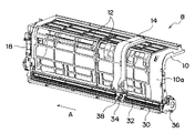
図4及び図5に示されるように、フィルタ装置8は、フィルタ枠10と、フィルタ枠10に着脱自在に取り付けられたエアフィルタ12と、エアフィルタ12の上流側の面に沿って左右方向(水平方向)に摺動自在の吸引ノズル14と、フィルタ枠10の下端部に取り付けられるとともに吸引ノズル14の一端に接続された屈曲自在の吸引ホース16と、吸引ホース16に接続され空気と共に塵埃を吸引して排気及び排塵を行う排気ファン18と、排気ファン18に一端が接続され他端が室外に開口した排気ダクト(図示せず)とを備えている。フィルタ枠10の片側(図4では右側)には、エアフィルタ12の清掃時以外に吸引ノズル14を保持する吸引ノズル保持部10aが形成されており、エアフィルタ12は、吸引ノズル保持部10aを除くフィルタ枠10に着脱自在に取り付けられている。
As shown in FIGS. 4 and 5, the
吸引ホース16は、その一端部が排気ファン18に接続される一方、その他端部は排気ファン18から見て吸引ノズル14の下端部における反対側の側面に接続されており、その中間部は略U字状に屈曲している。また、吸引ホース16の長さは、吸引ノズル14がフィルタ枠10の吸引ノズル保持部10aに位置したとき、吸引ホース16が多少ゆとりをもって屈曲できるように設定されている。なお、排気ファン18に屈曲性のない吸引ダクトの一端を接続するとともに、吸引ダクトを本体2の幅方向における中央部近傍まで延在させ、吸引ダクトの他端に吸引ホース16を接続するようにしてもよい。
One end of the
図4乃至図8に示されるように、吸引ノズル14は、縦長に形成されて中間部が屈曲しており、エアフィルタ12に面する側に所定幅のスリット状の吸入口が設けられている。また、吸引ノズル14の内部には、吸入口に沿って摺動しループ状に形成された所定幅のフィルム状ベルト19が収容され、ベルト19には所定幅の吸引孔19aが形成されるとともに、エアフィルタ12に付着した塵埃の除去効率を向上させるためのブラシ21が吸引孔19aに隣接して設けられている。吸引孔19aは吸入口と重なる位置に形成されており、その長さは、例えば吸入口の全長の1/16に設定されている。ベルト19は、吸引ノズル14に固定されたステッピングモータ20により上下方向のいずれにも自由に駆動できるように構成されている。上述したように、ベルト19はループ状に形成されているが、リール等を設けてベルト19を巻き取るように構成することもできる。
As shown in FIGS. 4 to 8, the
吸引ノズル14はさらに、下端部に取り付けられた二つのローラ22と、上端部に取り付けられた一つのローラ24とを有しており、図9及び図10に示されるように、これら複数のローラ22,24にはガイド溝22a,24aが形成されている。また、下端部のローラ22は、フィルタ枠10の下端部に設けられた略コ字状の下部レール26に摺動自在に取り付けられており、下部レール26に形成された1条の凸部26aがローラ22のガイド溝22aに遊挿されている。一方、上端部のローラ24は、フィルタ枠10の上端部に螺着された板金製保持部材28に摺動自在に保持されており、フィルタ枠10の上端部に形成された1条の凸部10bがローラ24のガイド溝24aに遊挿されている。
The
なお、エアフィルタ12はフィルタ枠10に着脱自在に取り付けられているが、フィルタ枠10は本体2の一部であってもよく、エアフィルタ12を本体2に固定し、着脱できない構成にしてもよい。
Although the
フィルタ枠10の下端部には、幅方向全長にわたって延びるラック30が一体的に形成されており、ラック30の前方には平行に延びる駆動軸32が設けられ、ラック30と噛み合うウォームギヤ34が駆動軸32に摺動自在に取り付けられている。駆動軸32は軸心に直交する方向の断面が六角形を呈しており、その一端はフィルタ枠10の片側(図4では左側)に回動自在に取り付けられるとともに、その他端はフィルタ枠10の反対側に設けられた駆動源としてのギヤボックス36に挿入されている。また、ウォームギヤ34は、その中央部に形成されたギヤ部34aと、その両端部に形成された円筒部34bと、軸心に沿って延びる六角形の駆動軸挿入孔を有し、この駆動軸挿入孔に駆動軸32は遊挿されている。
A
一方、吸引ノズル14の下端部には、駆動連結部材38が取り付けられており、駆動連結部材38は、吸引ノズル14に螺着される基部38aと、基部38aから前方に向かって延びる二つのフック38bとを備えている。二つのフック38bの間にはウォームギヤ34のギヤ部34aが遊挿されるギヤ収容スペース38cが形成されており、ギヤ収容スペース38cの長さはギヤ部34aの長さより僅かに長く設定されている。また、ウォームギヤ34は、その両端部に形成された円筒部34bが駆動連結部材38の二つのフック38bに係止されることで、駆動連結部材38と一体的に左右方向に摺動する。
On the other hand, a
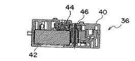
また、ギヤボックス36は、図11乃至図15に示されるように、ケーシング40に収容されたギヤ付きステッピングモータ42と減速機構とを有し、減速機構は、ステッピングモータ42のギヤと噛み合う第1ギヤ44と、第1ギヤ44と噛み合う第2ギヤ46と、第2ギヤ46と噛み合う第3ギヤ48と、第3ギヤ48と噛み合う出力ギヤ50とにより構成されている。出力ギヤ50には六角形の駆動軸挿入孔50aが形成されており、駆動軸32の一端が駆動軸挿入孔50aに挿入されている。
Further, as shown in FIGS. 11 to 15, the
上記構成のフィルタ装置8の動作を以下説明する。
空気調和機の運転停止後に、排気ファン18が運転を開始すると、吸引ホース16に連通する吸引ノズル14の吸入口から空気を吸い込み始める。同時にステッピングモータ42に通電されて、減速機構を介して駆動軸32及びウォームギヤ34が一体的に回転する。ウォームギヤ34はフィルタ枠10の下端部に形成されたラック30と噛み合っていることから、ウォームギヤ34は図4の矢印Aの方向に摺動することになるので、初期位置(フィルタ枠10の吸引ノズル保持部10a)に保持されていた吸引ノズル14はエアフィルタ12の一端側から他端側に向かって矢印Aの方向に摺動しながら、エアフィルタ12の表面に付着した塵埃を吸い取り、排気ダクトを介して室外へ排出する。吸引ノズル14がエアフィルタ12の表面の一部を全面清掃し、エアフィルタ12の他端側に到達すると、ステッピングモータ20が作動して吸引孔19aが形成されたベルト19が所定の長さ(吸引孔19aの長さに相当)だけ上昇した後、ステッピングモータ42が逆回転する。その結果、吸引ノズル14は初期位置に戻る方向に移動して、再度エアフィルタ12の表面を清掃する。
The operation of the
When the
なお、吸引ノズル14の摺動に際し、吸引ノズル14に設けられた複数のローラ22,24が、下部レール26に形成された凸部26a及びフィルタ枠10の上端部に形成された凸部10bに沿ってそれぞれ回転するが、ラック30にウォームギヤ34が嵌合していることから、ラック30から離反する方向の力が駆動軸32に加わる。しかしながら、下部レール26の凸部26aがローラ22のガイド溝22aに遊挿されていることから、ラック30から離反する方向への駆動軸32の撓みが防止され、凸部26aが駆動軸32の撓み防止手段として作用する。
When the
また、フィルタ枠10の両端部にはそれぞれ一つのリミットスイッチ(図示せず)が取り付けられており、リミットスイッチが電気的に接続された制御器(図示せず)により吸引ノズル14の駆動制御を行っている。
In addition, one limit switch (not shown) is attached to each end of the
この駆動制御を下記の数値を例にとり図16のフローチャートを参照しながらさらに詳述する。
・ラック長さ:708mm
・ラックの歯数:224
・ラック全長をノズルが1方向に移動するのに必要なパルス数:26250パルス
・1秒当たりのパルス数:250パルス/秒
This drive control will be further described in detail with reference to the flowchart of FIG.
-Rack length: 708mm
・ Number of teeth on rack: 224
-Number of pulses required for the nozzle to move in one direction over the entire length of the rack: 26250 pulses-Number of pulses per second: 250 pulses / second
この場合、吸引ノズル14が正常に左右方向に摺動すれば、105(26250/250)秒で吸引ノズル14がラック全長を1方向に移動することになる。以下の説明では、エアフィルタ12を上下方向に16等分し、下から順に1段目(最下段)、2段目、3段目、…、16段目(最上段)と呼ぶものとする。
In this case, if the
出荷時あるいはリセット時には吸引孔19aは、フィルタ枠10の初期位置(吸引ノズル保持部10a)の下端部に位置しており、ステップS1において空気調和機が運転された後停止すると、ステップS2において吸引ノズル14がエアフィルタ12の一端側から他端側に向かって矢印Aの方向に摺動しながら、エアフィルタ12の最下段表面に付着した塵埃を吸引し、排気ファン18により排気ダクトを介して排気(排塵)する。
At the time of shipment or reset, the
次のステップS3において所定数のパルス(26250パルス)がステッピングモータ42に印可されたかどうかを判定し、所定数のパルスが印可されていればステップS4に移行する一方、所定数のパルスが印可されていない場合にはステップS3の判定を繰り返す。ステップS4においては、フィルタ枠10の排気ファン18側に配置されたリミットスイッチに入力があったかどうかを判定し、入力があった場合には、ステップS5において吸引孔19aを有するベルト19をステッピングモータ20によりエアフィルタ12の2段目まで上昇させた後、ステッピングモータ42を逆回転させて吸引ノズル14を矢印Aの逆方向に初期位置に向かって摺動させる。
In the next step S3, it is determined whether or not a predetermined number of pulses (26250 pulses) are applied to the stepping
次のステップS6において所定数のパルス(26250パルス)がステッピングモータ42に印可されたかどうかを判定し、所定数のパルスが印可されていればステップS7に移行する一方、所定数のパルスが印可されていない場合にはステップS6の判定を繰り返す。ステップS7においては、フィルタ枠10の初期位置側に配置されたリミットスイッチに入力があったかどうかを判定し、入力があった場合には、ステップS8において吸引ノズル14を停止させる。
In the next step S6, it is determined whether or not a predetermined number of pulses (26250 pulses) are applied to the stepping
ステップS9においては、吸引孔19aがエアフィルタ12の最上段に到達したかどうかを判定し、最上段に到達していると判定されると、ステップS10において吸引孔19aを最下段まで移動させる一方、吸引孔19aがエアフィルタ12の最上段にはまだ到達していないと判定されると、吸引孔19aはその位置(初期位置)に待機する。
In step S9, it is determined whether or not the
ステップS11において空気調和機が再度運転された後停止すると、ステップS12において所定時間(例えば、24時間)経過したかどうかを判定し、所定時間経過したと判定されると、ステップS13においてベルト19を1段上昇させ、ステップS2に戻る。一方、ステップS12において所定時間がまだ経過していないと判定されると、ステップS11に戻る。
When the air conditioner is stopped after being operated again in step S11, it is determined whether or not a predetermined time (for example, 24 hours) has elapsed in step S12. If it is determined that the predetermined time has elapsed, the
なお、ステップS4あるいはステップS7において、リミットスイッチに入力がないと判定されると、ステップS14に移行し、吸引ノズル14が所定時間(105秒)内に所定の位置(フィルタ枠10のいずれかの端部)に到達していないと判断し、吸引ノズル14の作動不良を室内ユニット本体に設けられた表示部に表示するか、あるいは音声告知する。すなわち、二つのリミットスイッチは吸引ノズル14の作動不良を検出するノズル作動不良検出手段として作用し、エアフィルタ12の脱着によりエアフィルタ12がフィルタ枠10に確実に取り付けられていない場合等に吸引ノズル14がエアフィルタ12の一部に当接して作動不能に陥ることがあり、このような場合には、居住者に告知するようにしている。
When it is determined in step S4 or step S7 that there is no input to the limit switch, the process proceeds to step S14, and the
この例では、空気調和機が1日1回運転されると仮定すると、吸引ノズル14はエアフィルタ12上を1日に1往復してエアフィルタ12全面の2/16の面積を清掃することになり、8日間でエアフィルタ12の全面清掃を完了する。
In this example, assuming that the air conditioner is operated once a day, the
また、空気調和機が連続運転される場合、その運転累積時間が所定の時間(例えば、24時間)を超えると、吸引ノズル14を強制的に1往復動作させるように設定することもできる。
In addition, when the air conditioner is continuously operated, the
さらに、遠隔操作装置(リモコン)に清掃ボタンを設け、清掃ボタンを押下することによりエアフィルタ12の全面清掃を行うようにすることもできる。
Furthermore, a cleaning button can be provided on the remote control device (remote control), and the entire surface of the
なお、上記実施の形態において、駆動軸32は軸心に直交する方向の断面が六角形を呈していると記載したが、断面形状は六角形に限定されるものではなく、六角形以外の多角形あるいは略D字状等の断面形状を有するものであってもよい。この場合、駆動軸32が遊挿されるウォームギヤ34の駆動軸挿入孔及び出力ギヤ50の駆動軸挿入孔50aは、駆動軸32の断面形状に対応した断面形状を呈することになる。
In the above embodiment, the
また、上記実施の形態においては、駆動源であるステッピングモータ42からの動力伝達手段として駆動軸32とウォームギヤ34とラック30とを採用したが、図17及び図18に示されるように、減速ギヤの出力ギヤ50に雄ねじを有する駆動軸54を取り付けるとともに、吸引ノズル14の下端部に取り付けられた駆動連結部材56に雌ねじを形成し、駆動軸54と駆動連結部材56とを螺合させて動力伝達手段を構成することもできる。この場合、ステッピングモータ42により駆動軸54を駆動することにより駆動連結部材56と吸引ノズル14とが一体的に摺動する。
In the above embodiment, the
さらに、上記実施の形態において、ラック30はフィルタ枠10の下端部に一体的に形成されているが、フィルタ枠10とは別体のラックを形成し、フィルタ枠10に固定するようにしてもよい。
Furthermore, in the above embodiment, the
本発明にかかる空気調和機によれば、室内ユニットに設けられたフィルタ装置の吸引ノズルの摺動をウォームギヤとラックとの嵌合あるいは雄ねじと雌ねじとの螺合により行うようにしたので、構成が簡素で駆動源からの駆動力伝達が確実に行われることになり、家庭用空気調和機として有用である。 According to the air conditioner of the present invention, the suction nozzle of the filter device provided in the indoor unit is slid by fitting the worm gear and the rack or by screwing the male screw and the female screw. It is simple and driving force transmission from the driving source is surely performed, and is useful as a home air conditioner.
2 室内ユニット本体、 4 熱交換器、 6 ファン、 8 フィルタ装置、
10 フィルタ枠、 10a 吸引ノズル保持部、 10b 凸部、
12 エアフィルタ、 14 吸引ノズル、 16 吸引ホース、
18 排気ファン、 19 ベルト、 19a 吸引孔、
20 ステッピングモータ、 21 ブラシ、 22,24 ローラ、
22a,24a ガイド溝、 26 下部レール、 28 保持部材、
30 ラック、 32 駆動軸、 34 ウォームギヤ、 34a ギヤ部、
34b 円筒部、 36 ギヤボックス、 38 駆動連結部材、 38a 基部、
38b フック、 38c ギヤ収容スペース、 40 ケーシング、
42 ステッピングモータ、 44 第1ギヤ、 46 第2ギヤ、
48 第3ギヤ、 50 出力ギヤ、 50a 駆動軸挿入孔、 54 駆動軸、
56 駆動連結部材。
2 indoor unit body, 4 heat exchanger, 6 fan, 8 filter device,
10 filter frame, 10a suction nozzle holding part, 10b convex part,
12 air filter, 14 suction nozzle, 16 suction hose,
18 exhaust fan, 19 belt, 19a suction hole,
20 stepping motors, 21 brushes, 22, 24 rollers,
22a, 24a guide groove, 26 lower rail, 28 holding member,
30 racks, 32 drive shafts, 34 worm gears, 34a gears,
34b cylindrical part, 36 gear box, 38 drive connecting member, 38a base part,
38b hook, 38c gear accommodation space, 40 casing,
42 stepping motor, 44 first gear, 46 second gear,
48 third gear, 50 output gear, 50a drive shaft insertion hole, 54 drive shaft,
56 Drive coupling member.
Claims (6)
前記熱交換器の上流側の前記本体にフィルタ枠を介して取り付けられたエアフィルタと、該エアフィルタに対向する吸入口を有しエアフィルタに付着した塵埃を吸入するための摺動自在の吸引ノズルと、該吸引ノズルを駆動機構を介して駆動する駆動源と、前記吸引ノズルに連通し空気と共に塵埃を吸引排気する排気装置と、該排気装置と前記吸引ノズルとを連通する連通手段とを備え、前記駆動機構を、前記駆動源に連結された駆動軸と、前記駆動軸に摺動自在に取り付けられ前記吸引ノズルと一体的に摺動するウォームギヤと、該ウォームギヤと噛み合うラックとにより構成するとともに、
前記吸引ノズルが所定の方向に摺動するベルトを備え、該ベルトに所定長さの吸引孔を形成し、空気調和機の停止中に、前記吸引ノズルを1方向に摺動させて前記エアフィルタの一部を清掃し、さらに前記吸引孔を前記1方向と直交する方向に前記吸引孔の長さだけ移動させた後、前記吸引ノズルを前記1方向の逆方向に摺動させて前記エアフィルタの別の一部を清掃し、
前記吸引ノズルの作動不良を検出するノズル作動不良検出手段を前記フィルタ枠に取り付けたことを特徴とする空気調和機。 An air conditioner having an indoor unit that houses a heat exchanger and a fan that blows out the air heat-exchanged in the heat exchanger into the room,
An air filter attached to the main body on the upstream side of the heat exchanger via a filter frame , and a slidable suction for sucking dust adhering to the air filter having a suction port facing the air filter A nozzle, a drive source that drives the suction nozzle via a drive mechanism, an exhaust device that communicates with the suction nozzle and sucks and exhausts dust together with air, and communication means that communicates the exhaust device and the suction nozzle. provided, constituting the drive mechanism, a drive shaft connected to the driving source, a worm gear slidably integrally slid with the suction nozzle attached to the drive shaft by a rack meshing with said worm gear With
The suction nozzle includes a belt that slides in a predetermined direction, a suction hole having a predetermined length is formed in the belt, and the air filter is slid in one direction while the air conditioner is stopped, so that the air filter The air filter is further moved by moving the suction hole in the direction perpendicular to the one direction by the length of the suction hole, and then sliding the suction nozzle in the opposite direction of the one direction. Clean another part of the
An air conditioner characterized in that nozzle malfunction detection means for detecting malfunction of the suction nozzle is attached to the filter frame .
前記熱交換器の上流側の前記本体にフィルタ枠を介して取り付けられたエアフィルタと、該エアフィルタに付着した塵埃を除去するための摺動自在の清掃用部材と、該清掃用部材を駆動機構を介して駆動する駆動源とを備え、前記駆動機構は、前記駆動源に連結された駆動軸と、前記駆動軸に摺動自在に取り付けられ前記清掃用部材と一体的に摺動するウォームギヤと、該ウォームギヤと噛み合うラックとにより構成されるとともに、
空気調和機の停止中に、前記清掃用部材を1方向に摺動させて前記エアフィルタの一部を清掃し、さらに前記清掃用部材を前記1方向の逆方向に摺動させて前記エアフィルタの別の一部を清掃し、
前記清掃用部材の作動不良を検出する清掃用部材作動不良検出手段を前記フィルタ枠に取り付けたことを特徴とする空気調和機。 An air conditioner having an indoor unit that houses a heat exchanger and a fan that blows out the air heat-exchanged in the heat exchanger into the room,
Driving an air filter mounted over the filter frame upstream the body of the heat exchanger, and the cleaning member slidable to remove the dust adhering to the air filter, the cleaning member A drive source that is driven via a mechanism, the drive mechanism being connected to the drive source, and a worm gear that is slidably attached to the drive shaft and slides integrally with the cleaning member And a rack meshing with the worm gear ,
While the air conditioner is stopped, the cleaning member is slid in one direction to clean a part of the air filter, and the cleaning member is slid in the opposite direction to the one direction. Clean another part of the
An air conditioner characterized in that a cleaning member malfunction detection means for detecting malfunction of the cleaning member is attached to the filter frame .
前記熱交換器の上流側の前記本体にフィルタ枠を介して取り付けられたエアフィルタと、該エアフィルタに付着した塵埃を除去するための清掃用部材と、該清掃用部材を駆動機構を介して駆動する駆動源とを備え、前記駆動機構は、前記駆動源に連結され雄ねじが形成された駆動軸と、前記清掃用部材に取り付けられ前記雄ねじと螺合する雌ねじとにより構成されるとともに、
空気調和機の停止中に、前記清掃用部材を1方向に摺動させて前記エアフィルタの一部を清掃し、さらに前記清掃用部材を前記1方向の逆方向に摺動させて前記エアフィルタの別の一部を清掃し、
前記清掃用部材の作動不良を検出する清掃用部材作動不良検出手段を前記フィルタ枠に取り付けたことを特徴とする空気調和機。 An air conditioner having an indoor unit that houses a heat exchanger and a fan that blows out the air heat-exchanged in the heat exchanger into the room,
An air filter attached to the main body upstream of the heat exchanger via a filter frame, a cleaning member for removing dust attached to the air filter, and the cleaning member via a drive mechanism A drive source for driving, and the drive mechanism includes a drive shaft connected to the drive source and formed with a male screw, and a female screw attached to the cleaning member and screwed with the male screw ,
While the air conditioner is stopped, the cleaning member is slid in one direction to clean a part of the air filter, and the cleaning member is slid in the opposite direction to the one direction. Clean another part of the
An air conditioner characterized in that a cleaning member malfunction detection means for detecting malfunction of the cleaning member is attached to the filter frame .
Priority Applications (2)
| Application Number | Priority Date | Filing Date | Title |
|---|---|---|---|
| JP2004325364A JP4435667B2 (en) | 2004-11-09 | 2004-11-09 | Air conditioner with indoor unit with automatic air filter cleaning function |
| CN 200510120265 CN1773185B (en) | 2004-11-09 | 2005-11-09 | Indoor unit air conditioner with automatic cleaning air filter function |
Applications Claiming Priority (1)
| Application Number | Priority Date | Filing Date | Title |
|---|---|---|---|
| JP2004325364A JP4435667B2 (en) | 2004-11-09 | 2004-11-09 | Air conditioner with indoor unit with automatic air filter cleaning function |
Publications (3)
| Publication Number | Publication Date |
|---|---|
| JP2006132903A JP2006132903A (en) | 2006-05-25 |
| JP2006132903A5 JP2006132903A5 (en) | 2007-11-08 |
| JP4435667B2 true JP4435667B2 (en) | 2010-03-24 |
Family
ID=36726594
Family Applications (1)
| Application Number | Title | Priority Date | Filing Date |
|---|---|---|---|
| JP2004325364A Active JP4435667B2 (en) | 2004-11-09 | 2004-11-09 | Air conditioner with indoor unit with automatic air filter cleaning function |
Country Status (2)
| Country | Link |
|---|---|
| JP (1) | JP4435667B2 (en) |
| CN (1) | CN1773185B (en) |
Families Citing this family (25)
| Publication number | Priority date | Publication date | Assignee | Title |
|---|---|---|---|---|
| JP2008032249A (en) * | 2006-07-26 | 2008-02-14 | Tsuchiya Tsco Co Ltd | Cleaning device for filter |
| KR101346830B1 (en) * | 2006-09-20 | 2014-01-22 | 엘지전자 주식회사 | Air conditioner |
| JP4287873B2 (en) * | 2006-08-31 | 2009-07-01 | 日立アプライアンス株式会社 | Air conditioner |
| JP2008194574A (en) * | 2007-02-09 | 2008-08-28 | Matsushita Electric Ind Co Ltd | Air conditioner |
| CN101256024B (en) * | 2007-03-01 | 2010-06-30 | 海尔集团公司 | Sleeve type filtering net dust collector for indoor set of air-conditioner |
| CN101256008B (en) * | 2007-03-01 | 2011-03-02 | 海尔集团公司 | Indoor set of air-conditioner with filtering net dust collector |
| CN101256009B (en) * | 2007-03-01 | 2010-07-07 | 海尔集团公司 | Indoor set of air-conditioner with dust collector |
| CN101270902B (en) * | 2007-03-22 | 2010-06-30 | 海尔集团公司 | Self-cleaning device of air conditioner dirt filtrating screen |
| CN101270913B (en) * | 2007-03-23 | 2012-01-11 | 海尔集团公司 | Cabinet air-conditioner dust gauze self-cleaning device and operation method thereof |
| CN101290152B (en) | 2007-04-18 | 2010-05-26 | 海尔集团公司 | Filter screen self-cleaning device |
| CN101290151B (en) | 2007-04-18 | 2010-05-26 | 海尔集团公司 | Air conditioner filter screen self-cleaning device |
| KR101346832B1 (en) * | 2007-04-19 | 2013-12-31 | 엘지전자 주식회사 | Air conditioner |
| JP4910995B2 (en) * | 2007-11-13 | 2012-04-04 | パナソニック株式会社 | Air conditioner |
| KR100907717B1 (en) * | 2008-01-08 | 2009-07-14 | 엘지전자 주식회사 | Air conditioner |
| CN101338924B (en) * | 2008-08-29 | 2010-06-02 | 广东志高空调有限公司 | Split hanging machine air conditioner with filtering net automatic cleaning device |
| JP2010201364A (en) * | 2009-03-04 | 2010-09-16 | Nippon Spindle Mfg Co Ltd | Air filter |
| JP6330775B2 (en) * | 2015-09-30 | 2018-05-30 | ダイキン工業株式会社 | Air conditioning indoor unit |
| CN105799977A (en) * | 2016-05-26 | 2016-07-27 | 淮南市宜留机械科技有限公司 | Vacuum package machine performing pumping filtration based on vacuum degree control module |
| JP6741915B2 (en) * | 2016-08-26 | 2020-08-19 | パナソニックIpマネジメント株式会社 | Air filter automatic cleaning device and air conditioner and air cleaner using the same |
| MY195128A (en) * | 2016-10-19 | 2023-01-11 | Sharp Kk | Air Purifier |
| CN108361848B (en) * | 2018-05-03 | 2024-03-08 | 广东美的制冷设备有限公司 | Air conditioner |
| CN109316840A (en) * | 2018-09-21 | 2019-02-12 | 安徽中研理工仪器设备有限公司 | A kind of air cleaning system |
| CN109224646A (en) * | 2018-09-21 | 2019-01-18 | 安徽中研理工仪器设备有限公司 | A kind of air cleaning facility with dust-extraction unit |
| CN109224648A (en) * | 2018-09-21 | 2019-01-18 | 安徽中研理工仪器设备有限公司 | A kind of filtering screen dust-cleaning device |
| KR102429373B1 (en) * | 2021-10-21 | 2022-08-04 | 김현민 | Ceiling Air Purifier and Sterilizer |
-
2004
- 2004-11-09 JP JP2004325364A patent/JP4435667B2/en active Active
-
2005
- 2005-11-09 CN CN 200510120265 patent/CN1773185B/en not_active Expired - Fee Related
Also Published As
| Publication number | Publication date |
|---|---|
| JP2006132903A (en) | 2006-05-25 |
| CN1773185B (en) | 2010-08-18 |
| CN1773185A (en) | 2006-05-17 |
Similar Documents
| Publication | Publication Date | Title |
|---|---|---|
| JP4435667B2 (en) | Air conditioner with indoor unit with automatic air filter cleaning function | |
| JP4779771B2 (en) | Recessed ceiling air conditioner | |
| JP4586973B2 (en) | Air conditioner | |
| JP2006132903A5 (en) | ||
| JP4840565B2 (en) | Air conditioner | |
| JP5441851B2 (en) | Air filter cleaning device and air conditioner indoor unit | |
| JP4050774B2 (en) | Air conditioner | |
| JP5334310B2 (en) | Air conditioner indoor unit | |
| JP4040433B2 (en) | Air conditioner indoor unit | |
| WO2008047662A1 (en) | Air conditioner with filter cleaning unit | |
| TWI344531B (en) | Air conditioner with indoor unit having automatic filter cleaning function | |
| JP5333022B2 (en) | Air conditioner indoor unit | |
| JP2020000989A (en) | Filter cleaning unit and air conditioner | |
| JP4269141B2 (en) | Air conditioner | |
| JP4428031B2 (en) | Air conditioner | |
| JP4665604B2 (en) | Air conditioner | |
| JP4165245B2 (en) | Air conditioner | |
| JP4165246B2 (en) | Air conditioner | |
| JP2009030855A (en) | Air conditioner | |
| JP4386544B2 (en) | Air conditioner | |
| KR20110116864A (en) | Air conditioner | |
| JP4014619B2 (en) | Air conditioner | |
| JP5284762B2 (en) | Filter cleaning device and air conditioning device | |
| JP5329166B2 (en) | Air conditioner | |
| JP5239629B2 (en) | Air conditioning indoor unit |
Legal Events
| Date | Code | Title | Description |
|---|---|---|---|
| A521 | Request for written amendment filed |
Free format text: JAPANESE INTERMEDIATE CODE: A523 Effective date: 20070727 |
|
| A621 | Written request for application examination |
Free format text: JAPANESE INTERMEDIATE CODE: A621 Effective date: 20070727 |
|
| RD03 | Notification of appointment of power of attorney |
Free format text: JAPANESE INTERMEDIATE CODE: A7423 Effective date: 20070727 |
|
| A521 | Request for written amendment filed |
Free format text: JAPANESE INTERMEDIATE CODE: A523 Effective date: 20071106 |
|
| A977 | Report on retrieval |
Free format text: JAPANESE INTERMEDIATE CODE: A971007 Effective date: 20090618 |
|
| A131 | Notification of reasons for refusal |
Free format text: JAPANESE INTERMEDIATE CODE: A131 Effective date: 20090630 |
|
| A521 | Request for written amendment filed |
Free format text: JAPANESE INTERMEDIATE CODE: A523 Effective date: 20090820 |
|
| TRDD | Decision of grant or rejection written | ||
| A01 | Written decision to grant a patent or to grant a registration (utility model) |
Free format text: JAPANESE INTERMEDIATE CODE: A01 Effective date: 20091124 |
|
| A01 | Written decision to grant a patent or to grant a registration (utility model) |
Free format text: JAPANESE INTERMEDIATE CODE: A01 |
|
| A61 | First payment of annual fees (during grant procedure) |
Free format text: JAPANESE INTERMEDIATE CODE: A61 Effective date: 20091224 |
|
| R150 | Certificate of patent or registration of utility model |
Ref document number: 4435667 Country of ref document: JP Free format text: JAPANESE INTERMEDIATE CODE: R150 |
|
| FPAY | Renewal fee payment (event date is renewal date of database) |
Free format text: PAYMENT UNTIL: 20130108 Year of fee payment: 3 |
|
| FPAY | Renewal fee payment (event date is renewal date of database) |
Free format text: PAYMENT UNTIL: 20130108 Year of fee payment: 3 |
|
| FPAY | Renewal fee payment (event date is renewal date of database) |
Free format text: PAYMENT UNTIL: 20140108 Year of fee payment: 4 |
|
| R250 | Receipt of annual fees |
Free format text: JAPANESE INTERMEDIATE CODE: R250 |
|
| R250 | Receipt of annual fees |
Free format text: JAPANESE INTERMEDIATE CODE: R250 |
|
| R250 | Receipt of annual fees |
Free format text: JAPANESE INTERMEDIATE CODE: R250 |
|
| R250 | Receipt of annual fees |
Free format text: JAPANESE INTERMEDIATE CODE: R250 |
|
| R250 | Receipt of annual fees |
Free format text: JAPANESE INTERMEDIATE CODE: R250 |
|
| R250 | Receipt of annual fees |
Free format text: JAPANESE INTERMEDIATE CODE: R250 |
|
| R250 | Receipt of annual fees |
Free format text: JAPANESE INTERMEDIATE CODE: R250 |
|
| R250 | Receipt of annual fees |
Free format text: JAPANESE INTERMEDIATE CODE: R250 |
|
| R250 | Receipt of annual fees |
Free format text: JAPANESE INTERMEDIATE CODE: R250 |
|
| R250 | Receipt of annual fees |
Free format text: JAPANESE INTERMEDIATE CODE: R250 |
|
| R250 | Receipt of annual fees |
Free format text: JAPANESE INTERMEDIATE CODE: R250 |
|
| R250 | Receipt of annual fees |
Free format text: JAPANESE INTERMEDIATE CODE: R250 |