EP2152666B1 - Enhanced process for the synthesis of urea - Google Patents
Enhanced process for the synthesis of urea Download PDFInfo
- Publication number
- EP2152666B1 EP2152666B1 EP08758715A EP08758715A EP2152666B1 EP 2152666 B1 EP2152666 B1 EP 2152666B1 EP 08758715 A EP08758715 A EP 08758715A EP 08758715 A EP08758715 A EP 08758715A EP 2152666 B1 EP2152666 B1 EP 2152666B1
- Authority
- EP
- European Patent Office
- Prior art keywords
- stream
- stripper
- reactor
- process according
- fed
- Prior art date
- Legal status (The legal status is an assumption and is not a legal conclusion. Google has not performed a legal analysis and makes no representation as to the accuracy of the status listed.)
- Active
Links
Images
Classifications
-
- C—CHEMISTRY; METALLURGY
- C07—ORGANIC CHEMISTRY
- C07C—ACYCLIC OR CARBOCYCLIC COMPOUNDS
- C07C273/00—Preparation of urea or its derivatives, i.e. compounds containing any of the groups, the nitrogen atoms not being part of nitro or nitroso groups
- C07C273/02—Preparation of urea or its derivatives, i.e. compounds containing any of the groups, the nitrogen atoms not being part of nitro or nitroso groups of urea, its salts, complexes or addition compounds
- C07C273/04—Preparation of urea or its derivatives, i.e. compounds containing any of the groups, the nitrogen atoms not being part of nitro or nitroso groups of urea, its salts, complexes or addition compounds from carbon dioxide and ammonia
-
- B—PERFORMING OPERATIONS; TRANSPORTING
- B01—PHYSICAL OR CHEMICAL PROCESSES OR APPARATUS IN GENERAL
- B01J—CHEMICAL OR PHYSICAL PROCESSES, e.g. CATALYSIS OR COLLOID CHEMISTRY; THEIR RELEVANT APPARATUS
- B01J2219/00—Chemical, physical or physico-chemical processes in general; Their relevant apparatus
- B01J2219/00002—Chemical plants
- B01J2219/00004—Scale aspects
- B01J2219/00006—Large-scale industrial plants
-
- B—PERFORMING OPERATIONS; TRANSPORTING
- B01—PHYSICAL OR CHEMICAL PROCESSES OR APPARATUS IN GENERAL
- B01J—CHEMICAL OR PHYSICAL PROCESSES, e.g. CATALYSIS OR COLLOID CHEMISTRY; THEIR RELEVANT APPARATUS
- B01J2219/00—Chemical, physical or physico-chemical processes in general; Their relevant apparatus
- B01J2219/00002—Chemical plants
- B01J2219/00027—Process aspects
- B01J2219/0004—Processes in series
-
- Y—GENERAL TAGGING OF NEW TECHNOLOGICAL DEVELOPMENTS; GENERAL TAGGING OF CROSS-SECTIONAL TECHNOLOGIES SPANNING OVER SEVERAL SECTIONS OF THE IPC; TECHNICAL SUBJECTS COVERED BY FORMER USPC CROSS-REFERENCE ART COLLECTIONS [XRACs] AND DIGESTS
- Y02—TECHNOLOGIES OR APPLICATIONS FOR MITIGATION OR ADAPTATION AGAINST CLIMATE CHANGE
- Y02P—CLIMATE CHANGE MITIGATION TECHNOLOGIES IN THE PRODUCTION OR PROCESSING OF GOODS
- Y02P20/00—Technologies relating to chemical industry
- Y02P20/50—Improvements relating to the production of bulk chemicals
- Y02P20/582—Recycling of unreacted starting or intermediate materials
Definitions
- the present invention relates to an enhanced process for the synthesis of urea.
- urea is effected by the reaction of ammonia and carbon dioxide at a high pressure and temperature, the subsequent separation of urea from the mixture containing the non-reacted products and recycling of the same to the reactor.
- step (1a) an exothermic equilibrium reaction takes place having a high reaction rate at room temperature, which, however, needs high pressures to reach a favourable equilibrium at the high temperature required by step (1b).
- reaction mixture which therefore includes, urea, water, ammonia, carbon dioxide and ammonium carbamate, with a relative concentration, in the different points of the reactor, depending on the different thermodynamic and kinetic factors which contribute to the process.
- Industrial processes for the production of urea normally carry out the synthesis in a reactor fed with NH 3 , CO 2 and with aqueous solutions of ammonium carbamate and/or carbamates coming from the recycled streams of the unconverted reagents, at temperatures ranging from 150 to 215°C, at pressures of at least 13.2 MPa (130 atm), with a NH 3/ CO 2 molar ratio ranging from 2.5 to 5, calculated with respect to the sum of the feeding streams, including ammonia and CO 2 , in the form of ammonium carbamate/carbonate.
- the effluent from the reactor still has considerable amounts of CO 2 , mainly in the form of unconverted ammonium carbamate.
- the control of the thermal level in the reactor is also an essential aspect for obtaining an optimal conversion, as temperatures which are either too low or too high lead to a reduction in the conversion due to the concurrence of various chemical and thermodynamic factors.
- the separation of urea from the water and unconverted reagents is carried out in several sections operating at decreasing temperatures and pressures, in which the decomposition is effected of ammonium carbamate to NH 3 and CO 2 , which are then made available for recycling to the reactor.
- the carbamate separation and recycling section has investment costs which heavily influence the cost of the final product.
- the urea contained in the aqueous solution leaving the reactor is separated from most of the non-transformed ammonium carbamate and from the excess ammonia used in the synthesis in suitable decomposers or strippers which operate at pressures substantially equal to or slightly lower than the synthesis pressure.
- the decomposition of ammonium carbamate is effected in the decomposers by supplying heat from the outside by means of indirect thermal exchange with a warmer fluid, normally vapour at 1.8 - 3.0 MPa, possibly stripping the decomposition products with inert gasses or ammonia or carbon dioxide or blends of inert gases with ammonia and/or carbon dioxide, the stripping possibly being effected using the excess ammonia, dissolved in the urea solution (self-stripping) consequently without separately feeding the stripping agent.
- a warmer fluid normally vapour at 1.8 - 3.0 MPa
- the carbamate decomposition products together with the possible stripping agents, with the exception of inert products, are normally condensed in condensers, obtaining a liquid which is recycled to the synthesis reactors.
- Particularly delicate steps in the urea synthesis process are those in which the ammonium carbamate is present at the highest temperature and concentration and consequently in the processes mentioned above these steps coincide with the decomposition-stripping steps and condensation of ammonium carbamate.
- One of the problems to be solved in these steps relates to the corrosion of the equipment involved due to the extremely aggressive characteristics which are created in their interior, both for the presence of saline solutions at a high concentration and phenomena due to mechanical stress of the surfaces in the decomposition areas and release of the gaseous phase.
- the known art suggests, for example, the use of special materials in the production of the stripper, particularly Ti, Zr, special stainless steels, urea grade, or a combination of the same. Still according to the state of the art, it is advantageous to feed a certain amount of air or other passivation agent, to prolong the resistance to corrosion of the materials, especially stainless steels, favouring the formation of a stable layer of oxide on the surfaces exposed to contact with the process fluids.
- the present invention can be inserted within the specific field of plants for the synthesis of urea with ammonia stripping, i.e. in plants in which the stripping action is facilitated in the stripper, in which the decomposition of carbamate takes place, by the ammonia present in the synthesis solution and/or by the ammonia fed for the purpose.
- the air which has not participated in the passivation reaction of the reactor flows out of the reactor together with the reaction mixture and is sent to the upper part of the stripper, from which it passes to the carbamate condenser and from there to the carbamate separator, consequently leaving the synthesis loop by means of the valve destined for the control of the pressure of the loop itself.
- the bottom of the stripper is excluded from the passivation action exerted by said air which is mixed at the inlet of the CO 2 compressor and sent to the reactor by means of the compressor itself.
- a further aspect to be considered in these plants is linked to the fact that the heat developed, and, more generally, the thermal level of the reactor in the feeding and reaction step of ammonia and carbon dioxide, with the formation of a liquid mixture containing ammonium carbamate, water, ammonia and urea, is controlled by operating on the thermal level of the CO 2 and/or ammonia streams, fed to the reactor and/or on the basis of the distribution of the same feeding streams between stripper, condenser and reactor and/or on the amount of heat removed in the condenser.
- This control of the thermal level is a further essential aspect for obtaining an optimal conversion in the reactor, as temperatures which are both too low and too high lead to a reduction in the conversion due to the concurrence of various chemical and thermodynamic factors.
- An object of the present invention therefore relates to an enhanced process for the synthesis of urea from ammonia and carbon dioxide, at a high pressure and temperature, with the formation of ammonium carbamate as intermediate product, which includes a high pressure synthesis section, comprising at least one separation step by decomposition-stripping with ammonia of the unconverted ammonium carbamate, carried out in a vertical apparatus, commonly called stripper, characterized in that said step also includes a feeding of a CO 2 stream, in the lower part of said stripper, heated to a temperature ranging from 130 to 230°C, preferably from 150 to 210°C, in a quantity ranging from 1 to 15%, preferably from 3 to 12% by weight, with respect to the total weight of the fresh CO 2 fed to the process, containing a passivating agent in such an amount that its equivalent content of O 2 in moles ranges from 0.05% to 0.80%, preferably from 0.10 to 0.40%, with respect to the moles of CO 2 of said stream.
- heating, heated referring to a stream of CO 2 means that said stream was subjected to an increase in temperature and has a temperature higher than the temperature of the CO 2 stream at the outlet of the final delivery of the compressor.
- the heated CO 2 stream fed to the stripper envisages a temperature ranging from 160 to 200°C.
- the fresh CO 2 not fed to the stripper is preferably sent to the reactor, but can also be partialized between the reactor and other steps of the process, such as the condenser and one or more separation steps at medium and low pressure.
- said heated CO 2 stream fed to the stripper is in a quantity ranging from 4 to 15%, more preferably from 4 to 12% by weight with respect to the total weight of the fresh CO 2 fed to the reactor.
- the compressed CO 2 stream fed to the reactor has a temperature ranging from 100 to 200°C, preferably from 130 to 185°C.
- the total compressed CO 2 can be subjected to heating, or the CO 2 stream alone to be fed to the stripper can be subjected to heating.
- the CO 2 stream fed to the stripper is heated in one or more of the intersteps of the CO 2 compressor.
- the compressed CO 2 stream fed to the reactor can also consist of a mixture in suitable percentages of a stream of compressed CO 2 and of one or more heated streams of CO 2 respectively, in one or more of the intersteps of the CO 2 compressor in delivery to the reactor, even more preferably, of a blend, in suitable percentages, of a compressed CO 2 stream and a heated CO 2 stream, at least in the interstep of the compressor which has the highest thermal level.
- the CO 2 stream sent to the reactor having a temperature ranging from 130 to 185°C, consists, for a quantity ranging from 0 to 40% by weight with respect to the total weight of said stream, of compressed CO 2 leaving the reactor at a temperature ranging from 100 to 120°C and for a quantity ranging from 60 to 100% by weight with respect to the total weight of said stream, of a stream of heated CO 2 in one or more of the heat exchange inter-steps of the compressor up to a temperature ranging from 140 to 200°C.
- the fresh CO 2 stream fed to the stripper which represents from 4 to 12% by weight of the CO 2 sent to the reactor, is heated to a temperature ranging from 160 to 200°C, in one or more of the heat exchange inter-steps of the CO 2 compressor.
- the CO 2 stream subjected to heating is heated in one or more of the intersteps of the CO 2 compressor, in delivery to the reactor, at the external side or tube side.
- the decomposition-stripping step of ammonium carbamate with ammonia is preferably a self-stripping step.
- the passivating agent is generally an oxidant which is preferably selected from air, oxygen, enriched air, hydrogen peroxide or mixtures thereof, preferably air.
- the process according to the present invention preferably comprises a synthesis phase of urea, wherein the ammonia/carbon dioxide molar ratio ranges from 2.7 to 5.0, more preferably from 3.0 to 4.0.
- a fundamental advantage of the enhanced process according to the present invention is that it allows a contemporaneous optimization of the processability of the reactor and stripper.
- the reactor operates at the optimal temperature to maximize the conversion, whereas, by passivation on the part of the passivating agent, in particular air, present in the heated CO 2 stream, the corrosion of the bottom of the stripper is prevented.
- This solution also leads to a recovery of heat, thus allowing a further enthalpic increase which gives an added value to the process according to the invention.
- the reactor can operate at the optimal temperature also heating the ammonia stream being fed to the same.
- a further advantage of the process according to the present invention consists of the elimination of compressors destined for sending passivation air to the bottom of the stripper, which represent a cost and require periodical maintenance.
- the present process also has the advantage of being easily and surprisingly effected by making a few, simple modifications in an already existing traditional plant, provided it has a high-pressure stripping section. In particular, it is sufficient to modify the plant so as to send to said stripping section a heated CO 2 stream in delivery of the CO 2 compressor to the reactor.
- a further advantage is the possibility of using the stripper in any urea-resistant steel material.
- the process according to the present invention is further illustrated by means of the enclosed figures, in which:
- the stream leaving the reactor and, in general, most of the liquid streams formed in the process normally contain ammonia in excess.
- liquid is used with reference to streams of mixtures consisting of a single liquid phase or a mixed liquid-vapour phase.
- gaseous is used, on the contrary, for streams or mixtures in which the liquid phase is substantially absent.
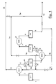
- the successive compression steps can be distinguished, C1, C2, C3 and C4 and the exchangers SC1, SC2, SC3, SC4 and SC5.
- the compression step C1, fed by line 1, is connected, through line 2, to a first exchanger SC1, having the highest thermal level, wherein the compressed CO 2 of the line 9d is heated and sent to the exit line 3 which is directly connected to the stripper S1 through the line 3b (15b in figure 2 ).
- the CO 2 coming from line 2 is cooled and leaves SC1 through line 4 which is connected to the second compression step C2, after passing through the exchanger SC2 (equipped with cooling water).
- the CO 2 leaving the compression step C2 is fed through line 5 to the exchanger SC3 from which it exits through line 6 to be connected with the compression step C3, after passing through the exchanger SC4 (equipped with cooling water). Cooling CO 2 is fed to the other side of the exchanger SC3, through the line 9b, which exits through line 7 and can be sent to the exchanger SC1 by means of lines 7b and 9d, and to the reactor, through line 7a, which is connected to line 3a and, subsequently, to line 9a (corresponding to 15a in figure 2 ).
- Line 3 is also connected to line 3a, which comes from the exchanger SC1 for a possible partialization between the reactor and the CO 2 stripper with the highest thermal level.
- the compression step C3 is then connected, by means of line 8 and after passing through the exchanger SC5 (equipped with cooling water), to the compression step C4, which, in turn, includes an exit line 9 which connects it directly to the exchanger SC3 by means of line 9b and to the reactor R1, through line 9a (15a in figure 2 ).
- Step C4 can also be directly connected to the exchanger SC1 through lines 9, 9c and 9d in succession.
- connection lines schematized in figure 1 allow, through the regulation of the valves indicated by means of the butterfly symbol, various flow compositions to be produced in order to obtain, for the CO 2 being fed to the reactor and stripper, the thermal levels and flow-rates selected in accordance with the present invention.
- some of the lines shown in figure 1 can, when necessary, be unused.
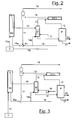
- the scheme of Figure 2 shows the reactor R1, which is connected, through the overflow T and line 10, with the stripper S1.
- the latter is connected, through line 11, with the urea separation and purification section P, from which, through line 12, carbamate is recycled to the condenser CC1 and urea is obtained, pure, solid or in aqueous solution, through line 20.
- the outlet of the gases from the stripper S1 is connected to the condenser CC1 through line 13.
- the outlet of the condenser CC1 is represented by line 14, which is then connected to the separator.
- the compression and heating unit of the carbon dioxide C is connected to the reactor (line 15a) and to the bottom of the stripper (line 15b).
- Line 16a is the feeding line of ammonia to the reactor, consisting of the feeding line of fresh and recovered ammonia 16, and the recycling line of the carbamate 17, at the outlet of the separator V.
- an outlet line 18 is envisaged for the discharge of inert products and for pressure control.
- the process according to the present invention can be effected in a plant having the above-mentioned characteristics, equipped with a synthesis section comprising the equipment and connections previously mentioned with reference to the scheme of figure 2 .
- This plant can be obtained as such starting from a new construction, or it can be simply and conveniently obtained by modifying a pre-existing plant for the synthesis of urea, equipped with a stripper suitable for operating under self-stripping conditions, by means of a connecting line between the CO 2 compressor and the lower section of said stripper, suitable for feeding a CO 2 stream to the stripper, in a quantity ranging from 1 to 15%, preferably from 4 to 12% by weight, with respect to the total weight of the fresh CO 2 fed to the plant.
- the fresh CO 2 stream is fed to the compression and heating unit C represented in detail in Figure 1 .
- This unit which represents the delivery compressor of the reactor, consists of a series of compression steps (normally four), at progressively higher pressures, intervalled by the same number of thermal exchange steps for the regulation of the temperature of the CO 2 .
- the pressures reached in the different compression steps depend on the construction and operative characteristics of the compressors and are normally known to technical experts in the art.
- the methods for the embodiment of the thermal exchange intersteps coupled with the compression steps, are also known.
- all the compressed CO 2 stream, through the four compression steps C1, C2, C3 and C4, by means of lines 2, 4, 5, 6 and 8, is sent, through lines 9 and 9b, to the exchanger SC3.
- the exchanger SC3 envisages that the CO 2 stream at the outlet through line 7, which is further heated, be partially sent, by means of lines 7b, to line 9d which feeds the exchanger SC1, and subsequently to the stripper S1 by means of lines 3 and 3b, and for the most part, through line 7a, it is conveyed to line 3a and from there sent directly to the reactor R1, by means of line 9a.
- the compressed CO 2 stream through passage in the four compression steps C1, C2, C3 and C4, by means of lines 2, 4, 5, 6 and 8, is partially sent, by means of lines 9 and 9a, directly to the reactor R1, and partially, by means of line 9b to the exchanger SC3.
- the CO 2 stream, further heated can follow one of the routes described in the previous paragraphs.
- the compressed CO 2 stream at the outlet of step C4 by means of line 9 is partially sent directly to the exchanger SC3 through lines 9c and 9d, and from this point to the stripper, through lines 3 and 3b,and for the most part to the exchanger SC3 and from there to the reactor R1, through lines 7, 7a, 3a and 9a.
- the fresh and recovered ammonia, compressed and fed through line 16 are sent as force fluids to the ejector E1, and are mixed here with the recovery and recycled stream (line 17), containing ammonia, carbamate and water, coming from the separator V and comprising the condensate produced in CC1 and the recovered product coming from section P.
- the resulting stream is sent to the reactor R1 through line 16a.
- a part of the ammonia can be fed to the stripper S1 (through line 16b).
- the above-mentioned streams mainly contain ammonia in the liquid state.
- the fresh CO 2 containing the passivating agent which can be air, for example, is sent, through lines 15a and 15b, to the reactor R1 and to the stripper S1 respectively.
- the overall feeding of the reactor consists of streams 15a and 16a, in turn fed by the recycled line 17.
- the recovered stream coming from unit P and containing water, ammonia and ammonium carbamate is sent to the condenser CC1, through line 12.
- the liquid stream thus obtained is fed to the separator V through line 14.
- a gaseous stream comprising inert gases and possibly residual oxygen in addition to small amounts of ammonia, CO 2 and H 2 O is flushed from the head of the separator V, through line 18.
- the stream 11 discharged from the bottom of the stripper S1, containing all the urea produced, is sent (line 11) to the subsequent purification and concentration steps, which are schematically combined in section P of Figure 2 .
- the enhanced process for the synthesis of urea from ammonia and carbon dioxide according to the present invention is used, for example, in a synthesis process comprising the following phases:
- This synthesis process is normally carried out in continuous in a suitable plant, fresh ammonia and carbon dioxide are continuously fed to the plant to balance the corresponding amount of reagents transformed into urea and removed at the outflow of the final separation and "prilling" section.
- the fresh ammonia can be fed directly to the reactor, or it can be sent, partially or totally, as stripping fluid into the stripper and/or sent directly to the condenser.
- the ammonia compressed and fed to the reactor has a temperature generally ranging from 0 to 130°C, preferably from 30 to 100°C.
- a greater thermal content of the ammonia stream can be preferred if a quantity of fresh CO 2 ranging from 8 to 15% of the total is fed to the stripper, in order to maintain a satisfactory thermal level in the reactor.
- the synthesis reactor normally operates at temperatures ranging from 150 to 215°C, preferably from 160 to 195°C, and at pressures ranging from 8.9MPa to 20 MPa, preferably from 11 MPa to 18 MPa, with ammonia/carbon dioxide molar ratios preferably ranging from 2.7 to 5.0, more preferably between 3.0 and 4.0.
- the regulation of the temperature of the reactor to the desired level can be effected according to any of the methods known in the art, for example, in addition to the above-mentioned heating of the ammonia stream in the feeding, by providing the reactor with a heating resistance, or by sending part of the gases coming out the stripper, directly to the reactor.
- the reactor is normally equipped with several plates, of a typology selected from those known in the art, in order to provide the optimal plug flow conditions, possibly also in the presence of biphasic systems.
- the reactor can also include various reaction zones, suitably interconnected with each other, possibly having different feeding streams.
- the reactor must have a liquid hold-up which is such as to allow a residence time of the same ranging from a few minutes to several tens of minutes, to allow the ammonium carbamate formed by the reaction of ammonia with carbon dioxide in the condensation step and/or in the reactor itself, to dehydrate to urea.
- the decomposition-stripping step is normally effected in a heated stripper, usually by means of indirect vapour at high pressure.
- the temperature of the stripper normally ranges from 160 to 220°C, preferably from 190 to 210°C, whereas the pressure is the same or slightly lower than that of the reactor.
- the ammonium carbamate tends to rapidly decompose, forming ammonia and carbon dioxide, whereas the urea already formed in the reactor remains substantially unaltered.
- Stripping is carried out using ammonia as carrier gas.
- the decomposition-stripping step is effected using, as carrier gas, the same ammonia which is in excess in the stream leaving the reactor. Further details on this preferred technology can be found, for example, in US patent 3,876,696 of SNAMPROGETTI , whose contents are enclosed herewith as reference. This latter technology is called "self-stripping".
- the decomposition step is generally effected in tube-bundle equipment, vertically oriented, with a liquid film drop.
- the mixture leaving the reactor is preferably fed to the head of the equipment and forms a film falling along the walls of the tube bundle.
- Other known equipment suitable for the purpose can also be used in the process of the present invention.
- the condensation step is normally effected in suitable condensers, for example tube-bundle condensers or surface condensers, in which the condensation heat is used for the heating of other fluids.
- the condensation heat is preferably used for producing vapour, but it can also be used for providing heat to one of the subsequent decomposition steps of the medium- or low-pressure ammonium carbamate.
- the condensation step can be carried out under normal conditions (temperature, pressure and composition) used in the known processes, provided the latter are such as to prevent the formation of solid ammonium carbamate in the condenser and/or in the lines leaving the same.
- the separation of urea from the ammonia and ammonium carbamate still present in the liquid stream leaving the decomposition-stripping step is effected in subsequent decomposition and separation sections, operating at medium (from 1.1 MPa to 2.5 MPa) and/or low pressure (from 0.2 to 0.8 MPa).
- This separation step can be effected by means of any of the methods described in specific literature of the field, which allow a recycled liquid stream containing an aqueous solution of ammonium carbamate and ammonia to be obtained, and possibly also a stream essentially consisting of ammonia.
- Suitable separation and purification sections are, for example, those schematized in figures 1 to 5 of the publication "Encyclopaedia of Chemical Technology" previously mentioned.
- the urea thus separated from the ammonium carbamate and ammonia is generally obtained as an aqueous solution which is subjected to a final vacuum dehydration step (down to 0.001 MPa), obtaining, on the one hand, water and, on the other, substantially pure urea sent to the normal "prilling" processes, etc..
- the final dehydration step and purification section of the wastewater leaving the synthesis plant are also included.
- the recycled ammonia and carbon dioxide can be present as carbonate, bicarbonate or ammonium carbamate, or a blend thereof, according to the temperature and pressure of the blend.
- compositions of the different streams are provided with reference to the base components, urea, ammonia, carbon dioxide and water, regardless of the fact that the carbon dioxide, in the liquid streams containing ammonia, is substantially in the form of ammonium carbamate.
- Air and inert products are indifferently indicated as "air”, as the oxygen consumption under regime conditions in the synthesis cycle is almost negligible.
- a process was carried out for the synthesis of urea, operating according to the present invention, wherein a stream of CO 2 , containing a suitable amount of air, coming from the compression and heating unit C, was fed to the bottom of the stripper S1. No further quantity of air or other passivating agent was introduced separately at the bottom of the stripper. Reference is made to the schemes shown in figure 1 and 2 .
- the liquid stream 10 discharged from the overflow T of the reactor, containing all the urea produced, was sent to the stripper S1.
- the stripper S1 is characterized by the following composition:
- the stripper runs at 15.2 MPa, at a bottom temperature of 205°C under self-stripping conditions.
- This stream was also heated to a temperature of 197°C by passage through the intersteps of the compressor, according to the following scheme, different from that of example 1.
- This stream was also heated to a temperature of 183°C according to the following scheme, different from that of example 1.
Landscapes
- Chemical & Material Sciences (AREA)
- Organic Chemistry (AREA)
- Organic Low-Molecular-Weight Compounds And Preparation Thereof (AREA)
Priority Applications (1)
| Application Number | Priority Date | Filing Date | Title |
|---|---|---|---|
| PL08758715T PL2152666T3 (pl) | 2007-05-22 | 2008-05-19 | Ulepszony sposób syntezy mocznika |
Applications Claiming Priority (2)
| Application Number | Priority Date | Filing Date | Title |
|---|---|---|---|
| IT001029A ITMI20071029A1 (it) | 2007-05-22 | 2007-05-22 | Procedimento migliorato per la sintesi di urea |
| PCT/EP2008/004119 WO2008141832A1 (en) | 2007-05-22 | 2008-05-19 | Enhanced process for the synthesis of urea |
Publications (2)
| Publication Number | Publication Date |
|---|---|
| EP2152666A1 EP2152666A1 (en) | 2010-02-17 |
| EP2152666B1 true EP2152666B1 (en) | 2013-03-27 |
Family
ID=38691998
Family Applications (1)
| Application Number | Title | Priority Date | Filing Date |
|---|---|---|---|
| EP08758715A Active EP2152666B1 (en) | 2007-05-22 | 2008-05-19 | Enhanced process for the synthesis of urea |
Country Status (14)
| Country | Link |
|---|---|
| US (1) | US8106241B2 (enExample) |
| EP (1) | EP2152666B1 (enExample) |
| JP (1) | JP5378361B2 (enExample) |
| CN (1) | CN101679224B (enExample) |
| AR (1) | AR066652A1 (enExample) |
| AU (1) | AU2008253238B2 (enExample) |
| CA (1) | CA2687668C (enExample) |
| EG (1) | EG25867A (enExample) |
| IT (1) | ITMI20071029A1 (enExample) |
| MX (1) | MX2009012541A (enExample) |
| PL (1) | PL2152666T3 (enExample) |
| RU (1) | RU2468002C2 (enExample) |
| UA (1) | UA97980C2 (enExample) |
| WO (1) | WO2008141832A1 (enExample) |
Families Citing this family (14)
| Publication number | Priority date | Publication date | Assignee | Title |
|---|---|---|---|---|
| EP2128129A1 (en) * | 2008-05-20 | 2009-12-02 | Urea Casale S.A. | Method for the modernization of a urea production plant |
| IT1395383B1 (it) * | 2009-09-09 | 2012-09-14 | Saipem Spa | Metodo di separazione di ammoniaca e diossido di carbonio da soluzioni acquose |
| ITMI20110804A1 (it) * | 2011-05-10 | 2012-11-11 | Saipem Spa | "processo ad alta resa per la sintesi dell'urea" |
| ITMI20111299A1 (it) * | 2011-07-12 | 2013-01-13 | Saipem Spa | Piatto di reattore per la produzione di urea, e reattore e processo di produzione di urea |
| ITMI20120013A1 (it) * | 2012-01-09 | 2013-07-10 | Saipem Spa | Procedimento per la sintesi di urea comprendente un flusso di passivazione a fondo stripper |
| CN102635536A (zh) * | 2012-05-03 | 2012-08-15 | 内蒙古乌拉山化肥有限责任公司 | 一种防止五段式co2压缩机中co2液化的方法 |
| NO341768B1 (no) * | 2012-08-29 | 2018-01-15 | Yara Int Asa | Passivert urea og gjødselblandinger |
| ITMI20130268A1 (it) | 2013-02-25 | 2014-08-26 | Saipem Spa | Metodo e sistema per l'abbattimento di ammoniaca da un flusso gassoso di scarico di un impianto urea |
| GB2530447B (en) * | 2013-05-28 | 2020-02-26 | Toyo Engineering Corp | Urea synthesis method |
| ITMI20131139A1 (it) * | 2013-07-05 | 2015-01-06 | Saipem Spa | Sistema e metodo di diffusione di gas per immettere un flusso gassoso, in particolare un flusso gassoso passivante, in un apparato di un impianto urea |
| CN103396343A (zh) * | 2013-07-09 | 2013-11-20 | 内蒙古鄂尔多斯联合化工有限公司 | 二氧化碳气提尿素生产工艺系统防腐方法 |
| IT201700090748A1 (it) * | 2017-08-04 | 2019-02-04 | Saipem Spa | Processo e impianto di produzione di urea facenti uso di co2 prodotta tramite ossi-combustione |
| IL297858A (en) | 2020-05-01 | 2023-01-01 | Monday Com Ltd | Digital processing systems and methods for improved networking and collaborative work management systems, methods and devices |
| JP2023108791A (ja) * | 2022-01-26 | 2023-08-07 | 東洋エンジニアリング株式会社 | 尿素合成方法 |
Family Cites Families (8)
| Publication number | Priority date | Publication date | Assignee | Title |
|---|---|---|---|---|
| US3137724A (en) * | 1956-04-16 | 1964-06-16 | Lonza Electric & Chem Works | Process for the pressure synthesis of urea |
| IL36465A (en) * | 1970-04-02 | 1974-07-31 | Zardi U | Process for the production of urea |
| JPS5746954A (en) * | 1980-09-05 | 1982-03-17 | Mitsui Toatsu Chem Inc | Synthesis of urea |
| NL8500591A (nl) * | 1985-03-04 | 1986-10-01 | Unie Van Kunstmestfab Bv | Werkwijze voor de bereiding van ureum uit kooldioxide en ammoniak. |
| NL8502227A (nl) * | 1985-08-12 | 1987-03-02 | Unie Van Kunstmestfab Bv | Werkwijze voor de bereiding van ureum. |
| IT1245396B (it) * | 1991-03-22 | 1994-09-20 | Snam Progetti | Procedimento per la produzione di urea ad elevata efficienza energetica |
| JP4358428B2 (ja) * | 2000-11-01 | 2009-11-04 | 東洋エンジニアリング株式会社 | 尿素製造方法 |
| RU2396253C2 (ru) * | 2005-03-03 | 2010-08-10 | Уреа Казале С.А. | Способ получения мочевины и установка для его осуществления |
-
2007
- 2007-05-22 IT IT001029A patent/ITMI20071029A1/it unknown
-
2008
- 2008-05-19 WO PCT/EP2008/004119 patent/WO2008141832A1/en not_active Ceased
- 2008-05-19 CN CN2008800194349A patent/CN101679224B/zh not_active Expired - Fee Related
- 2008-05-19 US US12/601,103 patent/US8106241B2/en not_active Expired - Fee Related
- 2008-05-19 UA UAA200911792A patent/UA97980C2/uk unknown
- 2008-05-19 AU AU2008253238A patent/AU2008253238B2/en not_active Ceased
- 2008-05-19 CA CA2687668A patent/CA2687668C/en not_active Expired - Fee Related
- 2008-05-19 MX MX2009012541A patent/MX2009012541A/es active IP Right Grant
- 2008-05-19 RU RU2009145646/04A patent/RU2468002C2/ru active
- 2008-05-19 JP JP2010508743A patent/JP5378361B2/ja not_active Expired - Fee Related
- 2008-05-19 PL PL08758715T patent/PL2152666T3/pl unknown
- 2008-05-19 EP EP08758715A patent/EP2152666B1/en active Active
- 2008-05-21 AR ARP080102142A patent/AR066652A1/es active IP Right Grant
-
2009
- 2009-11-22 EG EG2009111710A patent/EG25867A/xx active
Also Published As
| Publication number | Publication date |
|---|---|
| CA2687668A1 (en) | 2008-11-27 |
| JP5378361B2 (ja) | 2013-12-25 |
| US8106241B2 (en) | 2012-01-31 |
| JP2010527949A (ja) | 2010-08-19 |
| UA97980C2 (uk) | 2012-04-10 |
| CA2687668C (en) | 2016-03-22 |
| PL2152666T3 (pl) | 2013-09-30 |
| US20100217041A1 (en) | 2010-08-26 |
| AR066652A1 (es) | 2009-09-02 |
| CN101679224A (zh) | 2010-03-24 |
| CN101679224B (zh) | 2013-11-06 |
| AU2008253238A1 (en) | 2008-11-27 |
| WO2008141832A8 (en) | 2009-12-17 |
| MX2009012541A (es) | 2010-02-12 |
| AU2008253238B2 (en) | 2013-05-16 |
| WO2008141832A1 (en) | 2008-11-27 |
| ITMI20071029A1 (it) | 2008-11-23 |
| EP2152666A1 (en) | 2010-02-17 |
| RU2009145646A (ru) | 2011-06-27 |
| RU2468002C2 (ru) | 2012-11-27 |
| EG25867A (en) | 2012-09-12 |
Similar Documents
| Publication | Publication Date | Title |
|---|---|---|
| EP2152666B1 (en) | Enhanced process for the synthesis of urea | |
| CA2860715C (en) | Process for the synthesis of urea comprising a passivation stream at the stripper bottom | |
| CN115916745B (zh) | 热汽提尿素装置和方法 | |
| US8927770B2 (en) | High-yield process for the synthesis of urea | |
| US9512069B2 (en) | Urea synthesis process and plant |
Legal Events
| Date | Code | Title | Description |
|---|---|---|---|
| PUAI | Public reference made under article 153(3) epc to a published international application that has entered the european phase |
Free format text: ORIGINAL CODE: 0009012 |
|
| 17P | Request for examination filed |
Effective date: 20091113 |
|
| AK | Designated contracting states |
Kind code of ref document: A1 Designated state(s): AT BE BG CH CY CZ DE DK EE ES FI FR GB GR HR HU IE IS IT LI LT LU LV MC MT NL NO PL PT RO SE SI SK TR |
|
| AX | Request for extension of the european patent |
Extension state: AL BA MK RS |
|
| RAP1 | Party data changed (applicant data changed or rights of an application transferred) |
Owner name: SAIPEM S.P.A. |
|
| DAX | Request for extension of the european patent (deleted) | ||
| 17Q | First examination report despatched |
Effective date: 20110301 |
|
| GRAP | Despatch of communication of intention to grant a patent |
Free format text: ORIGINAL CODE: EPIDOSNIGR1 |
|
| GRAS | Grant fee paid |
Free format text: ORIGINAL CODE: EPIDOSNIGR3 |
|
| GRAA | (expected) grant |
Free format text: ORIGINAL CODE: 0009210 |
|
| AK | Designated contracting states |
Kind code of ref document: B1 Designated state(s): AT BE BG CH CY CZ DE DK EE ES FI FR GB GR HR HU IE IS IT LI LT LU LV MC MT NL NO PL PT RO SE SI SK TR |
|
| REG | Reference to a national code |
Ref country code: GB Ref legal event code: FG4D |
|
| REG | Reference to a national code |
Ref country code: CH Ref legal event code: EP |
|
| REG | Reference to a national code |
Ref country code: AT Ref legal event code: REF Ref document number: 603306 Country of ref document: AT Kind code of ref document: T Effective date: 20130415 |
|
| REG | Reference to a national code |
Ref country code: RO Ref legal event code: EPE |
|
| REG | Reference to a national code |
Ref country code: IE Ref legal event code: FG4D |
|
| REG | Reference to a national code |
Ref country code: CH Ref legal event code: NV Representative=s name: NIIZUMA WASNER GMBH PATENTANWALTSBUERO, CH |
|
| REG | Reference to a national code |
Ref country code: DE Ref legal event code: R096 Ref document number: 602008023253 Country of ref document: DE Effective date: 20130523 |
|
| REG | Reference to a national code |
Ref country code: NL Ref legal event code: T3 |
|
| PG25 | Lapsed in a contracting state [announced via postgrant information from national office to epo] |
Ref country code: NO Free format text: LAPSE BECAUSE OF FAILURE TO SUBMIT A TRANSLATION OF THE DESCRIPTION OR TO PAY THE FEE WITHIN THE PRESCRIBED TIME-LIMIT Effective date: 20130627 Ref country code: BG Free format text: LAPSE BECAUSE OF FAILURE TO SUBMIT A TRANSLATION OF THE DESCRIPTION OR TO PAY THE FEE WITHIN THE PRESCRIBED TIME-LIMIT Effective date: 20130627 Ref country code: SE Free format text: LAPSE BECAUSE OF FAILURE TO SUBMIT A TRANSLATION OF THE DESCRIPTION OR TO PAY THE FEE WITHIN THE PRESCRIBED TIME-LIMIT Effective date: 20130327 Ref country code: LT Free format text: LAPSE BECAUSE OF FAILURE TO SUBMIT A TRANSLATION OF THE DESCRIPTION OR TO PAY THE FEE WITHIN THE PRESCRIBED TIME-LIMIT Effective date: 20130327 |
|
| REG | Reference to a national code |
Ref country code: LT Ref legal event code: MG4D |
|
| PG25 | Lapsed in a contracting state [announced via postgrant information from national office to epo] |
Ref country code: LV Free format text: LAPSE BECAUSE OF FAILURE TO SUBMIT A TRANSLATION OF THE DESCRIPTION OR TO PAY THE FEE WITHIN THE PRESCRIBED TIME-LIMIT Effective date: 20130327 Ref country code: SI Free format text: LAPSE BECAUSE OF FAILURE TO SUBMIT A TRANSLATION OF THE DESCRIPTION OR TO PAY THE FEE WITHIN THE PRESCRIBED TIME-LIMIT Effective date: 20130327 Ref country code: FI Free format text: LAPSE BECAUSE OF FAILURE TO SUBMIT A TRANSLATION OF THE DESCRIPTION OR TO PAY THE FEE WITHIN THE PRESCRIBED TIME-LIMIT Effective date: 20130327 Ref country code: GR Free format text: LAPSE BECAUSE OF FAILURE TO SUBMIT A TRANSLATION OF THE DESCRIPTION OR TO PAY THE FEE WITHIN THE PRESCRIBED TIME-LIMIT Effective date: 20130628 |
|
| PG25 | Lapsed in a contracting state [announced via postgrant information from national office to epo] |
Ref country code: BE Free format text: LAPSE BECAUSE OF FAILURE TO SUBMIT A TRANSLATION OF THE DESCRIPTION OR TO PAY THE FEE WITHIN THE PRESCRIBED TIME-LIMIT Effective date: 20130327 Ref country code: HR Free format text: LAPSE BECAUSE OF FAILURE TO SUBMIT A TRANSLATION OF THE DESCRIPTION OR TO PAY THE FEE WITHIN THE PRESCRIBED TIME-LIMIT Effective date: 20130327 |
|
| REG | Reference to a national code |
Ref country code: PL Ref legal event code: T3 |
|
| PG25 | Lapsed in a contracting state [announced via postgrant information from national office to epo] |
Ref country code: SK Free format text: LAPSE BECAUSE OF FAILURE TO SUBMIT A TRANSLATION OF THE DESCRIPTION OR TO PAY THE FEE WITHIN THE PRESCRIBED TIME-LIMIT Effective date: 20130327 Ref country code: IS Free format text: LAPSE BECAUSE OF FAILURE TO SUBMIT A TRANSLATION OF THE DESCRIPTION OR TO PAY THE FEE WITHIN THE PRESCRIBED TIME-LIMIT Effective date: 20130727 Ref country code: CZ Free format text: LAPSE BECAUSE OF FAILURE TO SUBMIT A TRANSLATION OF THE DESCRIPTION OR TO PAY THE FEE WITHIN THE PRESCRIBED TIME-LIMIT Effective date: 20130327 Ref country code: EE Free format text: LAPSE BECAUSE OF FAILURE TO SUBMIT A TRANSLATION OF THE DESCRIPTION OR TO PAY THE FEE WITHIN THE PRESCRIBED TIME-LIMIT Effective date: 20130327 Ref country code: ES Free format text: LAPSE BECAUSE OF FAILURE TO SUBMIT A TRANSLATION OF THE DESCRIPTION OR TO PAY THE FEE WITHIN THE PRESCRIBED TIME-LIMIT Effective date: 20130708 Ref country code: PT Free format text: LAPSE BECAUSE OF FAILURE TO SUBMIT A TRANSLATION OF THE DESCRIPTION OR TO PAY THE FEE WITHIN THE PRESCRIBED TIME-LIMIT Effective date: 20130729 |
|
| PG25 | Lapsed in a contracting state [announced via postgrant information from national office to epo] |
Ref country code: CY Free format text: LAPSE BECAUSE OF FAILURE TO SUBMIT A TRANSLATION OF THE DESCRIPTION OR TO PAY THE FEE WITHIN THE PRESCRIBED TIME-LIMIT Effective date: 20130327 |
|
| PG25 | Lapsed in a contracting state [announced via postgrant information from national office to epo] |
Ref country code: MC Free format text: LAPSE BECAUSE OF FAILURE TO SUBMIT A TRANSLATION OF THE DESCRIPTION OR TO PAY THE FEE WITHIN THE PRESCRIBED TIME-LIMIT Effective date: 20130327 |
|
| PG25 | Lapsed in a contracting state [announced via postgrant information from national office to epo] |
Ref country code: DK Free format text: LAPSE BECAUSE OF FAILURE TO SUBMIT A TRANSLATION OF THE DESCRIPTION OR TO PAY THE FEE WITHIN THE PRESCRIBED TIME-LIMIT Effective date: 20130327 |
|
| PLBE | No opposition filed within time limit |
Free format text: ORIGINAL CODE: 0009261 |
|
| STAA | Information on the status of an ep patent application or granted ep patent |
Free format text: STATUS: NO OPPOSITION FILED WITHIN TIME LIMIT |
|
| GBPC | Gb: european patent ceased through non-payment of renewal fee |
Effective date: 20130627 |
|
| REG | Reference to a national code |
Ref country code: IE Ref legal event code: MM4A |
|
| 26N | No opposition filed |
Effective date: 20140103 |
|
| REG | Reference to a national code |
Ref country code: DE Ref legal event code: R097 Ref document number: 602008023253 Country of ref document: DE Effective date: 20140103 |
|
| PG25 | Lapsed in a contracting state [announced via postgrant information from national office to epo] |
Ref country code: IE Free format text: LAPSE BECAUSE OF NON-PAYMENT OF DUE FEES Effective date: 20130519 Ref country code: GB Free format text: LAPSE BECAUSE OF NON-PAYMENT OF DUE FEES Effective date: 20130627 |
|
| PG25 | Lapsed in a contracting state [announced via postgrant information from national office to epo] |
Ref country code: MT Free format text: LAPSE BECAUSE OF FAILURE TO SUBMIT A TRANSLATION OF THE DESCRIPTION OR TO PAY THE FEE WITHIN THE PRESCRIBED TIME-LIMIT Effective date: 20130327 |
|
| PG25 | Lapsed in a contracting state [announced via postgrant information from national office to epo] |
Ref country code: TR Free format text: LAPSE BECAUSE OF FAILURE TO SUBMIT A TRANSLATION OF THE DESCRIPTION OR TO PAY THE FEE WITHIN THE PRESCRIBED TIME-LIMIT Effective date: 20130327 |
|
| PG25 | Lapsed in a contracting state [announced via postgrant information from national office to epo] |
Ref country code: HU Free format text: LAPSE BECAUSE OF FAILURE TO SUBMIT A TRANSLATION OF THE DESCRIPTION OR TO PAY THE FEE WITHIN THE PRESCRIBED TIME-LIMIT; INVALID AB INITIO Effective date: 20080519 Ref country code: LU Free format text: LAPSE BECAUSE OF NON-PAYMENT OF DUE FEES Effective date: 20130519 |
|
| REG | Reference to a national code |
Ref country code: FR Ref legal event code: PLFP Year of fee payment: 9 |
|
| PGFP | Annual fee paid to national office [announced via postgrant information from national office to epo] |
Ref country code: FR Payment date: 20160412 Year of fee payment: 9 Ref country code: RO Payment date: 20160405 Year of fee payment: 9 |
|
| PG25 | Lapsed in a contracting state [announced via postgrant information from national office to epo] |
Ref country code: RO Free format text: LAPSE BECAUSE OF NON-PAYMENT OF DUE FEES Effective date: 20170519 |
|
| REG | Reference to a national code |
Ref country code: FR Ref legal event code: ST Effective date: 20180131 |
|
| PG25 | Lapsed in a contracting state [announced via postgrant information from national office to epo] |
Ref country code: FR Free format text: LAPSE BECAUSE OF NON-PAYMENT OF DUE FEES Effective date: 20170531 |
|
| PG25 | Lapsed in a contracting state [announced via postgrant information from national office to epo] |
Ref country code: PL Free format text: LAPSE BECAUSE OF NON-PAYMENT OF DUE FEES Effective date: 20190519 |
|
| P01 | Opt-out of the competence of the unified patent court (upc) registered |
Effective date: 20230420 |
|
| PGFP | Annual fee paid to national office [announced via postgrant information from national office to epo] |
Ref country code: AT Payment date: 20230519 Year of fee payment: 16 |
|
| P02 | Opt-out of the competence of the unified patent court (upc) changed |
Effective date: 20231116 |
|
| REG | Reference to a national code |
Ref country code: AT Ref legal event code: MM01 Ref document number: 603306 Country of ref document: AT Kind code of ref document: T Effective date: 20240519 |
|
| PG25 | Lapsed in a contracting state [announced via postgrant information from national office to epo] |
Ref country code: AT Free format text: LAPSE BECAUSE OF NON-PAYMENT OF DUE FEES Effective date: 20240519 |
|
| PG25 | Lapsed in a contracting state [announced via postgrant information from national office to epo] |
Ref country code: AT Free format text: LAPSE BECAUSE OF NON-PAYMENT OF DUE FEES Effective date: 20240519 |
|
| PGFP | Annual fee paid to national office [announced via postgrant information from national office to epo] |
Ref country code: NL Payment date: 20250526 Year of fee payment: 18 |
|
| PGFP | Annual fee paid to national office [announced via postgrant information from national office to epo] |
Ref country code: DE Payment date: 20250528 Year of fee payment: 18 |
|
| PGFP | Annual fee paid to national office [announced via postgrant information from national office to epo] |
Ref country code: IT Payment date: 20250522 Year of fee payment: 18 |
|
| PGFP | Annual fee paid to national office [announced via postgrant information from national office to epo] |
Ref country code: CH Payment date: 20250601 Year of fee payment: 18 |