EP2152193B1 - Applicator - Google Patents
Applicator Download PDFInfo
- Publication number
- EP2152193B1 EP2152193B1 EP08766962.8A EP08766962A EP2152193B1 EP 2152193 B1 EP2152193 B1 EP 2152193B1 EP 08766962 A EP08766962 A EP 08766962A EP 2152193 B1 EP2152193 B1 EP 2152193B1
- Authority
- EP
- European Patent Office
- Prior art keywords
- applicator
- linkage
- handle
- needle
- shroud
- Prior art date
- Legal status (The legal status is an assumption and is not a legal conclusion. Google has not performed a legal analysis and makes no representation as to the accuracy of the status listed.)
- Active
Links
- 241001465754 Metazoa Species 0.000 claims description 13
- 230000015572 biosynthetic process Effects 0.000 claims description 10
- 239000012530 fluid Substances 0.000 claims description 8
- 230000000295 complement effect Effects 0.000 claims description 4
- 238000000034 method Methods 0.000 description 4
- 230000009471 action Effects 0.000 description 3
- 239000007789 gas Substances 0.000 description 3
- 230000007246 mechanism Effects 0.000 description 3
- 208000012266 Needlestick injury Diseases 0.000 description 2
- 239000003814 drug Substances 0.000 description 2
- 230000008569 process Effects 0.000 description 2
- 241000283690 Bos taurus Species 0.000 description 1
- 206010069803 Injury associated with device Diseases 0.000 description 1
- 241000282887 Suidae Species 0.000 description 1
- 230000002411 adverse Effects 0.000 description 1
- 230000008901 benefit Effects 0.000 description 1
- 230000008859 change Effects 0.000 description 1
- 230000000994 depressogenic effect Effects 0.000 description 1
- 229940079593 drug Drugs 0.000 description 1
- 230000000694 effects Effects 0.000 description 1
- 230000036541 health Effects 0.000 description 1
- 238000002347 injection Methods 0.000 description 1
- 239000007924 injection Substances 0.000 description 1
- 239000003915 liquefied petroleum gas Substances 0.000 description 1
- 230000004048 modification Effects 0.000 description 1
- 238000012986 modification Methods 0.000 description 1
- 230000035515 penetration Effects 0.000 description 1
- 239000004540 pour-on Substances 0.000 description 1
- 230000001225 therapeutic effect Effects 0.000 description 1
- 239000002699 waste material Substances 0.000 description 1
- 230000036642 wellbeing Effects 0.000 description 1
Images


Classifications
-
- A—HUMAN NECESSITIES
- A61—MEDICAL OR VETERINARY SCIENCE; HYGIENE
- A61D—VETERINARY INSTRUMENTS, IMPLEMENTS, TOOLS, OR METHODS
- A61D7/00—Devices or methods for introducing solid, liquid, or gaseous remedies or other materials into or onto the bodies of animals
-
- A—HUMAN NECESSITIES
- A61—MEDICAL OR VETERINARY SCIENCE; HYGIENE
- A61M—DEVICES FOR INTRODUCING MEDIA INTO, OR ONTO, THE BODY; DEVICES FOR TRANSDUCING BODY MEDIA OR FOR TAKING MEDIA FROM THE BODY; DEVICES FOR PRODUCING OR ENDING SLEEP OR STUPOR
- A61M5/00—Devices for bringing media into the body in a subcutaneous, intra-vascular or intramuscular way; Accessories therefor, e.g. filling or cleaning devices, arm-rests
- A61M5/178—Syringes
- A61M5/31—Details
- A61M5/32—Needles; Details of needles pertaining to their connection with syringe or hub; Accessories for bringing the needle into, or holding the needle on, the body; Devices for protection of needles
- A61M5/3205—Apparatus for removing or disposing of used needles or syringes, e.g. containers; Means for protection against accidental injuries from used needles
- A61M5/321—Means for protection against accidental injuries by used needles
- A61M5/3243—Means for protection against accidental injuries by used needles being axially-extensible, e.g. protective sleeves coaxially slidable on the syringe barrel
- A61M5/326—Fully automatic sleeve extension, i.e. in which triggering of the sleeve does not require a deliberate action by the user
- A61M2005/3267—Biased sleeves where the needle is uncovered by insertion of the needle into a patient's body
-
- A—HUMAN NECESSITIES
- A61—MEDICAL OR VETERINARY SCIENCE; HYGIENE
- A61M—DEVICES FOR INTRODUCING MEDIA INTO, OR ONTO, THE BODY; DEVICES FOR TRANSDUCING BODY MEDIA OR FOR TAKING MEDIA FROM THE BODY; DEVICES FOR PRODUCING OR ENDING SLEEP OR STUPOR
- A61M5/00—Devices for bringing media into the body in a subcutaneous, intra-vascular or intramuscular way; Accessories therefor, e.g. filling or cleaning devices, arm-rests
- A61M5/178—Syringes
- A61M5/20—Automatic syringes, e.g. with automatically actuated piston rod, with automatic needle injection, filling automatically
- A61M5/204—Automatic syringes, e.g. with automatically actuated piston rod, with automatic needle injection, filling automatically connected to external reservoirs for multiple refilling
-
- A—HUMAN NECESSITIES
- A61—MEDICAL OR VETERINARY SCIENCE; HYGIENE
- A61M—DEVICES FOR INTRODUCING MEDIA INTO, OR ONTO, THE BODY; DEVICES FOR TRANSDUCING BODY MEDIA OR FOR TAKING MEDIA FROM THE BODY; DEVICES FOR PRODUCING OR ENDING SLEEP OR STUPOR
- A61M5/00—Devices for bringing media into the body in a subcutaneous, intra-vascular or intramuscular way; Accessories therefor, e.g. filling or cleaning devices, arm-rests
- A61M5/178—Syringes
- A61M5/31—Details
- A61M5/32—Needles; Details of needles pertaining to their connection with syringe or hub; Accessories for bringing the needle into, or holding the needle on, the body; Devices for protection of needles
- A61M5/3205—Apparatus for removing or disposing of used needles or syringes, e.g. containers; Means for protection against accidental injuries from used needles
Definitions
- the present invention relates to applicators, and in particular, but not exclusively, to applicators of the type used to inject remedies into animals.
- remedial is used herein to include any drug, medicine, remedy, or therapeutic preparation, when in a form suitable for dispensing from an applicator, or more specifically an injector, as the context requires.
- Some injectors of the prior art attempt to reduce the risk of accidental needle stick by covering the needle of the injector with a retractable shroud.
- the shroud may be spring loaded so that it retracts automatically as the needle is inserted into the animal.
- injectors such as that described in US patent No. 5,951,516 , which discloses an applicator with a needle shroud and a trigger which must be depressed to an intermediate position before the shroud can be retracted.
- a trigger lock provided on the body of the injector prevents the trigger from being moved to an operational position until the shroud has been retracted by a desired amount, corresponding to a desired penetration of the needle into the animal. Only when this has occurred can the trigger be moved to the operational position and the dose injected.
- the injector described in US 5,951,516 is powered by a pressurised gas such as a compressed air or liquid petroleum gas. It would be desirable to develop an injector which had a high level of safety but which did not depend on a pressurised gas as a power source. It would also be advantageous if the safety mechanism did not depend on any sharp edge abutment, as these may be prone to wear.
- the needle has a threaded portion with engages a complementary threaded portion provided on the outlet of the injector.
- the needle is provided with a formation with which a suitable tool, such as a spanner, can be engaged in order to rotate the needle and thereby engage or disengage the needle with the outlet.
- the injectors of the prior art may require the needle shroud, if provided, to be retracted or removed during this process, leaving the sharp end of the needle exposed.
- an applicator including;
- the linkage is biased towards the over-centre locked position.
- the linkage unlocking means includes a trigger.
- At least one of the connections between the ends of the hinged linkage and the first and second members allows relative movement between the linkage and the respective member in addition to the rotational movement.
- the relative movement includes slideable movement between the respective member and the end of the hinged linkage.
- At least one of the connections between the ends of the hinged linkage and the first and second members includes a pin slideably engaged with a slot.
- the applicator is suitable for applying an animal remedy to an animal.
- first and second members are handles.
- the applicator is an injector.
- an applicator including;
- the flow control means includes a second handle, wherein relative movement of the second handle towards the first handle causes the remedy to flow from the outlet
- the applicator includes a second hinged linkage having a first end rotatably engaged with the first handle, a second end rotatably engaged with the second handle, and a hinge intermediate the first and second ends, the second linkage moveable between a collapsed position wherein the hinge is on a first side of a notional axis extending between first and second ends, and an over-centre locked position wherein the hinge is on an opposite side of the notional axis between the first and second ends and the second hinged linkage prevents relative movement of the second handle towards the first handle, the arrangement being such that movement of the first hinged linkage to the collapsed position causes the hinge of the second hinged linkage to move from the over-centre locked position to the first side of the notional axis between the first and second ends of the second hinged linkage, so that the second hinged linkage can be moved to the collapsed position as
- At least one of the connections between the ends of the second hinged linkage and the handles allows relative movement between the linkage and the respective handle in addition to the rotational movement.
- the relative movement includes slideable movement between the end of the second hinged linkage and the respective handle.
- At least one of the connections between the ends of the second hinged linkage and the handles includes a pin slideably engaged with a slot.
- the body is connected to a first end of the first handle.
- the second handle is rotatably connected to the first handle at a distal end to the body.
- the shroud is biased towards the extended position.
- the applicator is an injector and the application means is a needle.
- the shroud is detachable from the injector and is operable in a second mode of operation as a means for removing the needle from the injector, the shroud including a body provided with a cavity shaped and dimensioned to receive the needle when in use in the second mode of operation, the cavity including a formation adapted to engage a complementary formation of the needle so that rotation of the needle shroud causes rotation of the needle, thereby allowing disengagement of the needle from the injector with the needle housed in the cavity.
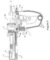
- an applicator is shown according to one embodiment of the present invention.
- the applicator is configured as an injector, generally referenced 100.
- the injector 100 has a body 1 which is provided with a first handle 2.
- the handle 2 is typically formed as an integral component with the body 1.
- the body is provided with a cylinder or barrel 3 within which a plunger 3a is reciprocable in order to move fluid from an inlet 4 to an outlet 5 of the injector 100.
- the plunger is actuated by relative movement of the first handle 2 towards the second handle 6, which causes a remedy in the barrel 3 to move through the outlet 5 and hence through a needle 7 which is attached to the outlet 5.
- a needle shroud 8 is connected to the body 1 so as to be slideable between the extended position shown in Figure 1 , and the retracted position shown in Figures 3 and 4 .
- the needle shroud 8 is preferably biased towards the extended position by a suitable biasing means such as a spring 9 positioned between the needle shroud 8 and the body 1.
- a mechanism is provided to lock the needle shroud 8 in the extended position when the injector 100 is not in use.
- a linkage 10 is rotatably connected to the needle shroud 8 at a first end 11 and to the first handle 2 at a second end 12.
- the linkage 10 is provided with a hinge 13 between the first and second ends which divides the linkage into a first segment 10a connected to the shroud 8 and a second segment 10b connected to the first handle 2.
- a biasing means such as a torsion spring 14 biases the linkage 10 towards an over-centre locked position, as illustrated in Figure 1 .
- a biasing means such as a torsion spring 14 biases the linkage 10 towards an over-centre locked position, as illustrated in Figure 1 .
- Any suitable means of locking the linkage when it is in this position may be used, but in a preferred embodiment the first segment 10a of the linkage 10 is provided with a stop portion 15, best seen in Figure 2 .
- the stop portion 15 engages a portion of the second segment 10b and prevents the hinge 13 from rotating so as to move the hinge 13 any further away from a notional axis A which extends between the centres of the rotatable connections at the first and second ends of the linkage 10.
- the linkage 10 With the linkage 10 in the over-centre locked position the linkage 10 acts as a substantially rigid strut when subject to a force aligned with the notional axis A. The linkage 10 therefore prevents the needle shroud 8 from moving away from its extended position when in the over-centre locked position.
- a linkage unlocking means moves the linkage 10 against the action of the biasing means 14 so that the hinge 13 is on the opposite side of the notional axis A, as shown in Figure 2 .
- the linkage unlocking means is a trigger 16 which is slideably connected to the first handle 2 and is positioned so as to move into engagement with the linkage 10 when operated by the user, thereby moving the hinge 13 away from the locked position.
- other suitable means of moving the linkage 10 away from the over-centre locked position will be apparent to those skilled in the art.
- the needle shroud 8 can be retracted to the position shown in Figure 3 , for example as the needle 7 is inserted into the subject animal.
- a second hinged linkage 17 is provided between the first handle 2 and second handle 6.
- the second linkage 17 is rotatably connected at a first end 18 to the first handle 2 and at a second, opposite end 19 to the second handle 6.
- the second linkage 17 is biased towards the over-centre locked position shown in Figures 1 and 2 by a suitable biasing means such as a torsion spring 20.
- a first segment 17a of the second linkage 17 is provided with a stop portion 21 which engages a suitable portion of a second segment 17b of the linkage 17, and prevents the hinge 22 from rotating so as to move the hinge 22 any further away from a notional axis B which extends between the centres of the rotatable connections at the first and second ends of the linkage 17.
- the second linkage 17 With the second linkage 17 in the over-centre locked position shown in Figures 1 and 2 the second linkage 17 is substantially rigid to forces aligned with axis B, and the first handle 2 and second handle 6 cannot be moved together. In this way the chances of accidental dispensing of the remedy are greatly reduced.
- the needle shroud 8 In order to unlock the handles 2, 6, the needle shroud 8 must be moved to the fully retracted position shown in Figure 3 .
- a second linkage unlocking portion of the first linkage 10 for example the stop portion 15, engages the second linkage 17 and moves it from the over-centre locked position shown in Figures 1 and 2 , to the unlocked position shown in Figure 3 .
- the first linkage 10 and second linkage 17 may have a pivot axis in common, as seen in the figures. This is not essential, but it does assist in positioning the linkages 10, 17 so that the first linkage 10 can be used to unlock the second linkage 17 when the first linkage 10 moves to the collapsed position.
- a dosage control means may be provided to allow adjustment of the dose delivered.
- a suitable dosage control means is described in the applicant's New Zealand patent No. 521084 .
- the needle 7 is withdrawn from the animal and the handles 2, 6 are allowed to move apart under the action of a suitable biasing means such as a torsion spring 23, thereby drawing a new dose of the remedy from a suitable source through the inlet 4 and into the barrel 3.
- Biasing means 9 move the needle shroud 8 back to the extended position, and biasing means 14 and 20 move the linkages 10, 17 back to their over-centre locked positions.
- the injector 100 is therefore reset and ready to dispense a further dose.
- the over-centre action of the linkage 17 may mean that the linkage 17 determines the position of the plunger when in the reset position, rather than the plunger returning to a hard stop. This may lead to small deviations in the dose delivered by the applicator.
- the connection between the end 19 of the second linkage 17 and the second handle 6 may allow a small amount of relative movement.
- an additional linkage (not shown) may be provided between the end 19 and the second handle 6 to allow for this movement.
- the end 19 of the second linkage 17 is provided with an elongate or slotted aperture 26 within which a pin 27 is provided.
- the pin 27 is connected to the second handle.
- the elongate or slotted aperture 26 allows a small amount of sliding movement between handle and the second linkage 17 in addition to allowing rotational movement.
- the second linkage 17 may be provided with projecting pins or similar (not shown) which engage with slots provided in the second handle.
- a similar system may be used at the opposite end of the second linkage.
- the aperture may simply be oversized relative to the pin, rather than slotted.
- the stop portion 15 is connected to the second segment 10b of the first linkage 10, rather than to the first segment 10a as shown in the embodiment shown in Figures 1-4 .
- the second segment 10b of the first linkage is provided with means to unlock the second segment which includes at least one abutment portion 28 which abuts an abutment portion 29 provided on the first segment 17a of the second linkage 17 when the first linkage 10 is collapsed. This abutment causes the second linkage 17 to move away from its over-centre locked position to its collapsed position.
- the injector may be adapted so that the plunger is actuated by an alternative means, such as a pressurised gas.
- the remedy may be supplied to the inlet under pressure and the movement of the handles may actuate a valve which allows the remedy to flow from the inlet to the outlet. Suitable means for controlling the volume of remedy delivered may be required with this embodiment.
- the first linkage 10 may be omitted, and some other means of locking the needle shroud may be provided, if required.
- the second linkage 17 may be unlocked by some other suitable means such as, for example, a trigger. This method of locking the flow control means may also be used with dispensing means other than injectors, for example pour on applicators and the like.
- the applicator may be provided with the first linkage 10, but the second linkage 17 may be omitted.
- This configuration may be useful where the applicator has a particularly delicate application means, such as a needle or a delicate nozzle, but where the remedy being dispensed is not harmful to humans.
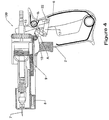
- the needle shroud 8 is provided with means for assisting with the removal of the needle 7.
- the needle shroud 8 is detachable from the body of the injector 100.
- the shroud 8 is also provided with a cavity 30 shaped and dimensioned to receive the needle 7 when the user wishes to remove the needle 7 from the injector 100.
- the cavity 30 has a formation 31, best seen in Figure 1A , preferably provided at or adjacent the mouth 32 of the cavity 30, which is shaped and dimensioned to engage a complementary formation 33 of the needle 7.
- the formation may be a square drive formation as shown in Figure 1A .
- the provision of the cavity 30 and formation 31 allows the point of the needle 7 to covered when the needle 7 is removed from the injector 100.
- the cavity mouth 32 may be provided at either end of the body of the shroud 8. In some embodiments (not shown) the cavity may extend through the body of the shroud 8, but it is preferred that the cavity is shaped so that the needle point 34 can not protrude from the cavity 30.
- Some needles for use with such injectors are supplied in a two-part plastic sheath (not shown).
- One part of the sheath has a socket for the needle hub and the needle sits into the socket with the needle cannula protruding into the sheath so that the sharp end of needle is protected.
- the sheath can be held and used as a tool to attach the needle to the luer lock of an injector.
- the aperture 24 in the needle shroud 8 of the present invention is preferably dimensioned to allow such a sheath to be inserted through the front of the shroud so that the needles can be fitted and removed without having to remove the shroud 8 from the injector 100.
- the needle shroud 8 described above may be used with other injectors of the prior art, but when used in association with the injector 100 described above there is provided an injector which allows a user to inject a remedy into an animal, and to change a needle of the injector, with minimal risk of needle stick or of accidental delivery of the remedy into the user.
- applicator shown in the figures is adapted for use with a remote supply of remedy, for example from a backpack
- those skilled in the art will appreciate that the invention may also be used with applicators which are provided with a bottle mount on which a bottle containing the remedy may be mounted. Still other embodiments may be loaded with a cartridge or vial.
Landscapes
- Health & Medical Sciences (AREA)
- Life Sciences & Earth Sciences (AREA)
- Veterinary Medicine (AREA)
- Engineering & Computer Science (AREA)
- Wood Science & Technology (AREA)
- Zoology (AREA)
- Animal Behavior & Ethology (AREA)
- General Health & Medical Sciences (AREA)
- Public Health (AREA)
- Infusion, Injection, And Reservoir Apparatuses (AREA)
Priority Applications (1)
| Application Number | Priority Date | Filing Date | Title |
|---|---|---|---|
| EP17187344.1A EP3266413B1 (en) | 2007-05-21 | 2008-05-21 | Needle shroud |
Applications Claiming Priority (2)
| Application Number | Priority Date | Filing Date | Title |
|---|---|---|---|
| NZ555327A NZ555327A (en) | 2007-05-21 | 2007-05-21 | An applicator which has a two stage interlock that protects from æneedle stickÆ injuries by covering the needle with a shield which also needs to be retracted before a dose can be administered |
| PCT/NZ2008/000113 WO2008143529A2 (en) | 2007-05-21 | 2008-05-21 | Applicator |
Related Child Applications (2)
| Application Number | Title | Priority Date | Filing Date |
|---|---|---|---|
| EP17187344.1A Division EP3266413B1 (en) | 2007-05-21 | 2008-05-21 | Needle shroud |
| EP17187344.1A Division-Into EP3266413B1 (en) | 2007-05-21 | 2008-05-21 | Needle shroud |
Publications (3)
| Publication Number | Publication Date |
|---|---|
| EP2152193A2 EP2152193A2 (en) | 2010-02-17 |
| EP2152193A4 EP2152193A4 (en) | 2016-09-28 |
| EP2152193B1 true EP2152193B1 (en) | 2017-11-15 |
Family
ID=40032297
Family Applications (2)
| Application Number | Title | Priority Date | Filing Date |
|---|---|---|---|
| EP08766962.8A Active EP2152193B1 (en) | 2007-05-21 | 2008-05-21 | Applicator |
| EP17187344.1A Active EP3266413B1 (en) | 2007-05-21 | 2008-05-21 | Needle shroud |
Family Applications After (1)
| Application Number | Title | Priority Date | Filing Date |
|---|---|---|---|
| EP17187344.1A Active EP3266413B1 (en) | 2007-05-21 | 2008-05-21 | Needle shroud |
Country Status (13)
| Country | Link |
|---|---|
| US (1) | US8641682B2 (pt) |
| EP (2) | EP2152193B1 (pt) |
| JP (1) | JP5399380B2 (pt) |
| CN (1) | CN101765413B (pt) |
| AU (1) | AU2008253832B2 (pt) |
| BR (1) | BRPI0811897B1 (pt) |
| CA (1) | CA2694239C (pt) |
| ES (1) | ES2656796T3 (pt) |
| MX (1) | MX2009012605A (pt) |
| NZ (1) | NZ555327A (pt) |
| RU (1) | RU2009147274A (pt) |
| WO (1) | WO2008143529A2 (pt) |
| ZA (1) | ZA200909137B (pt) |
Families Citing this family (16)
| Publication number | Priority date | Publication date | Assignee | Title |
|---|---|---|---|---|
| US8366679B2 (en) * | 2009-04-16 | 2013-02-05 | Cole Isolation Technique, Llc | Self filling injection device |
| CN102448528B (zh) | 2009-05-28 | 2013-11-27 | 西姆克罗有限公司 | 皮肤夹持装置、包括皮肤夹持装置的注射器和执行皮下注射的方法 |
| CH705153A1 (fr) * | 2011-06-24 | 2012-12-31 | Heidi Hall | Mors et système pour envoyer une substance visqueuse et/ou liquide dans la bouche d'un animal. |
| CA153896S (en) * | 2013-07-17 | 2014-08-06 | Henke Sass Wolf Gmbh | Injector |
| CN104771244B (zh) * | 2014-01-13 | 2017-10-27 | 中国农业科学院饲料研究所 | 一种动物用注射装置 |
| KR101636299B1 (ko) * | 2015-04-02 | 2016-07-05 | 김광현 | 피부시술장치 |
| US10342742B2 (en) * | 2015-04-07 | 2019-07-09 | Kenneth Edward Ruda | Bolus feeding device |
| CN107397606B (zh) * | 2017-08-28 | 2019-01-22 | 信阳农林学院 | 一种兽医用注射器 |
| CN107737390A (zh) * | 2017-11-29 | 2018-02-27 | 林融纲 | 一种脂肪注射枪 |
| AU2019283460A1 (en) * | 2018-06-06 | 2020-11-19 | Datamars Limited | Improvements in, or relating to, applicators |
| CN110051453B (zh) * | 2019-05-31 | 2024-04-16 | 广西壮族自治区畜牧研究所 | 动物皮内注射装置及其注射辅助器 |
| CN110339430B (zh) * | 2019-08-15 | 2024-05-10 | 北京天悦生科技有限公司 | 一种可标记式连续兽药注射器 |
| CN112220582A (zh) * | 2020-10-27 | 2021-01-15 | 青海省大通种牛场 | 一种快速注射枪 |
| CN112641499A (zh) * | 2020-12-31 | 2021-04-13 | 杭州堃博生物科技有限公司 | 推送装置及蒸汽消融设备 |
| CN113331980B (zh) * | 2021-05-10 | 2024-02-23 | 武汉市正华精机技术发展有限公司 | 兽用无针注射器 |
| CN115998989A (zh) * | 2022-12-02 | 2023-04-25 | 北京快舒尔医疗技术有限公司 | 注射设备和包括该注射设备的注射系统 |
Family Cites Families (31)
| Publication number | Priority date | Publication date | Assignee | Title |
|---|---|---|---|---|
| US2624338A (en) * | 1950-10-31 | 1953-01-06 | Frank C Moore | Dispensing gun |
| US3261243A (en) * | 1964-09-18 | 1966-07-19 | Wallace D Ellison | Toggle clamp having a lock mechanism engageable as an over-center position is approached |
| US3517668A (en) * | 1967-10-16 | 1970-06-30 | Bio Neering Inc | Multiple dosage veterinary injection gun |
| IT969196B (it) * | 1972-11-25 | 1974-03-30 | Colombo A | Dispositivo per uso odontoiatrico specificamente atto alla anestesia intraligamentare |
| US4020838A (en) * | 1975-05-06 | 1977-05-03 | N.J. Phillips Pty. Limited | Animal dosing syringe |
| GB1565692A (en) | 1976-03-02 | 1980-04-23 | Wellcome Found | Luquid dispensing device |
| US4318559A (en) * | 1980-03-31 | 1982-03-09 | Johnston & Margolis, P.C. | Lock for sliding members |
| AU572322B2 (en) * | 1984-07-27 | 1988-05-05 | N.J. Phillips Pty. Limited | Tape dispenser |
| NZ212899A (en) * | 1984-07-31 | 1987-10-30 | Phillips Pty Ltd N J | Piston operated adjustable volume dose injector for animals |
| US4695274A (en) * | 1986-01-31 | 1987-09-22 | Fox Richard L | Protected hypodermic needle |
| US4772272A (en) * | 1987-05-11 | 1988-09-20 | Mcfarland Barton C | Needle protective sleeve |
| CN88200415U (zh) * | 1988-01-22 | 1988-12-14 | 张寂勇 | 计数连续刺种注射器 |
| US4850996A (en) * | 1988-02-22 | 1989-07-25 | Cree Ian C | Safety needle |
| US4911693A (en) * | 1988-10-17 | 1990-03-27 | Paris Frassetti R | Hypodermic syringe needle guard |
| US4946446A (en) * | 1989-06-14 | 1990-08-07 | Vadher Dinesh L | Retractable needle |
| US5049136A (en) * | 1990-01-10 | 1991-09-17 | Johnson Gerald W | Hypodermic needle with protective sheath |
| CN2085228U (zh) * | 1991-03-15 | 1991-09-25 | 靳贵 | 兽用全金属连续注射器 |
| FR2693112B1 (fr) * | 1992-07-01 | 1994-09-02 | Raymond Denance | Dispositif électromécanique d'injection à usage médical et vétérinaire actionné par une gâchette. |
| GB2288539B (en) * | 1994-04-21 | 1998-04-15 | Genesis Mfg Ltd | Device for injecting a substance into the body of an animal |
| AUPO742497A0 (en) * | 1997-06-18 | 1997-07-10 | N.J. Phillips Pty. Limited | An applicator |
| AUPO889497A0 (en) | 1997-09-01 | 1997-09-25 | N.J. Phillips Pty. Limited | An applicator |
| WO2000016832A1 (en) * | 1998-09-23 | 2000-03-30 | Koh Lawrence R | Needle point guard safety cap assembly |
| US6460787B1 (en) | 1998-10-22 | 2002-10-08 | Nordson Corporation | Modular fluid spray gun |
| JP2001170090A (ja) * | 1999-12-20 | 2001-06-26 | Fujihira Industry Co Ltd | 生物用注射器 |
| GB0214452D0 (en) | 2002-06-22 | 2002-07-31 | Liversidge Barry P | Medical needle assemblies |
| NZ521084A (en) | 2002-08-28 | 2005-01-28 | Simcro Tech Ltd | Selectable dosage dispensing apparatus |
| NZ524938A (en) * | 2003-03-24 | 2005-10-28 | Simcro Tech Ltd | Dispenser, for treating animals, with damping to avoid shock waves |
| MXPA06003096A (es) * | 2003-09-22 | 2006-05-31 | Smiths Medical Asd Inc | Ensamble de aguja de seguridad y metodo para hacer el mismo. |
| US20050137575A1 (en) * | 2003-12-18 | 2005-06-23 | Duke University | Minimally invasive injection devices and methods |
| GB0517699D0 (en) * | 2005-09-01 | 2005-10-05 | Owen Mumford Ltd | Needle shroud assembly |
| AU2006228045B2 (en) * | 2005-10-14 | 2011-11-24 | Covidien Lp | Apparatus for laparoscopic or endoscopic procedures |
-
2007
- 2007-05-21 NZ NZ555327A patent/NZ555327A/en unknown
-
2008
- 2008-05-21 JP JP2010509292A patent/JP5399380B2/ja active Active
- 2008-05-21 EP EP08766962.8A patent/EP2152193B1/en active Active
- 2008-05-21 WO PCT/NZ2008/000113 patent/WO2008143529A2/en active Application Filing
- 2008-05-21 CN CN2008800231691A patent/CN101765413B/zh active Active
- 2008-05-21 EP EP17187344.1A patent/EP3266413B1/en active Active
- 2008-05-21 US US12/451,566 patent/US8641682B2/en active Active
- 2008-05-21 RU RU2009147274/21A patent/RU2009147274A/ru not_active Application Discontinuation
- 2008-05-21 ES ES08766962.8T patent/ES2656796T3/es active Active
- 2008-05-21 MX MX2009012605A patent/MX2009012605A/es active IP Right Grant
- 2008-05-21 AU AU2008253832A patent/AU2008253832B2/en active Active
- 2008-05-21 BR BRPI0811897-3A patent/BRPI0811897B1/pt active IP Right Grant
- 2008-05-21 CA CA2694239A patent/CA2694239C/en active Active
-
2009
- 2009-12-21 ZA ZA2009/09137A patent/ZA200909137B/en unknown
Non-Patent Citations (1)
| Title |
|---|
| None * |
Also Published As
| Publication number | Publication date |
|---|---|
| CN101765413A (zh) | 2010-06-30 |
| WO2008143529A3 (en) | 2009-01-15 |
| US20100145283A1 (en) | 2010-06-10 |
| NZ555327A (en) | 2009-09-25 |
| EP2152193A4 (en) | 2016-09-28 |
| MX2009012605A (es) | 2010-03-08 |
| EP3266413A1 (en) | 2018-01-10 |
| WO2008143529A2 (en) | 2008-11-27 |
| US8641682B2 (en) | 2014-02-04 |
| JP2010527686A (ja) | 2010-08-19 |
| ZA200909137B (en) | 2014-05-28 |
| EP3266413B1 (en) | 2019-12-18 |
| RU2009147274A (ru) | 2011-06-27 |
| BRPI0811897B1 (pt) | 2019-07-30 |
| BRPI0811897A2 (pt) | 2014-11-18 |
| AU2008253832A1 (en) | 2008-11-27 |
| CA2694239A1 (en) | 2008-11-27 |
| CN101765413B (zh) | 2011-06-15 |
| AU2008253832B2 (en) | 2013-08-29 |
| EP2152193A2 (en) | 2010-02-17 |
| CA2694239C (en) | 2014-09-16 |
| ES2656796T3 (es) | 2018-02-28 |
| JP5399380B2 (ja) | 2014-01-29 |
Similar Documents
| Publication | Publication Date | Title |
|---|---|---|
| EP2152193B1 (en) | Applicator | |
| JP6871216B2 (ja) | 注射可能カートリッジ用自動注射器及びその為の駆動制御機構 | |
| CN101912649B (zh) | 用于注射所分配剂量的液体药物的设备 | |
| US9393369B2 (en) | Stabilized pen injector | |
| JP5718224B2 (ja) | 充填手段を備えた自己注入器 | |
| JP5524197B2 (ja) | 充填手段を備えた再利用可能な自己注入器 | |
| EP2464400B1 (en) | Cap for a portable medical delivery device and such a medical delivery device | |
| US7749201B2 (en) | Device for administering an injectable product with a lockable dose metering mechanism | |
| HUE028698T2 (en) | Automatic syringe | |
| CZ294265B6 (cs) | Injekční zařízení a způsob ovládání jeho pracovní činnosti | |
| EP1683538A1 (en) | Injection evice for administering a medication liquid | |
| US20220379034A1 (en) | Fixed dose injection device | |
| US20070016140A1 (en) | Exchangeable safety needle assembly | |
| EP2285438B1 (en) | Medicament delivery device | |
| NZ577306A (en) | Injector needle shroud | |
| US12097357B2 (en) | Stabilized pen injector | |
| KR20230110782A (ko) | 약물 전달 장치 |
Legal Events
| Date | Code | Title | Description |
|---|---|---|---|
| PUAI | Public reference made under article 153(3) epc to a published international application that has entered the european phase |
Free format text: ORIGINAL CODE: 0009012 |
|
| 17P | Request for examination filed |
Effective date: 20091221 |
|
| AK | Designated contracting states |
Kind code of ref document: A2 Designated state(s): AT BE BG CH CY CZ DE DK EE ES FI FR GB GR HR HU IE IS IT LI LT LU LV MC MT NL NO PL PT RO SE SI SK TR |
|
| AX | Request for extension of the european patent |
Extension state: AL BA MK RS |
|
| DAX | Request for extension of the european patent (deleted) | ||
| RIC1 | Information provided on ipc code assigned before grant |
Ipc: A61D 7/00 20060101AFI20160426BHEP Ipc: A61M 35/00 20060101ALI20160426BHEP Ipc: A61M 5/178 20060101ALI20160426BHEP |
|
| A4 | Supplementary search report drawn up and despatched |
Effective date: 20160826 |
|
| RIC1 | Information provided on ipc code assigned before grant |
Ipc: A61M 35/00 20060101ALI20160822BHEP Ipc: A61M 5/178 20060101ALI20160822BHEP Ipc: A61D 7/00 20060101AFI20160822BHEP |
|
| GRAP | Despatch of communication of intention to grant a patent |
Free format text: ORIGINAL CODE: EPIDOSNIGR1 |
|
| STAA | Information on the status of an ep patent application or granted ep patent |
Free format text: STATUS: GRANT OF PATENT IS INTENDED |
|
| RIN1 | Information on inventor provided before grant (corrected) |
Inventor name: WALKER, RODNEY GORDON Inventor name: EBBETT, TODD DONALD Inventor name: STANDING, COLIN ANTHONY |
|
| INTG | Intention to grant announced |
Effective date: 20170526 |
|
| RAP1 | Party data changed (applicant data changed or rights of an application transferred) |
Owner name: SIMCRO TECH LIMITED |
|
| GRAS | Grant fee paid |
Free format text: ORIGINAL CODE: EPIDOSNIGR3 |
|
| GRAA | (expected) grant |
Free format text: ORIGINAL CODE: 0009210 |
|
| STAA | Information on the status of an ep patent application or granted ep patent |
Free format text: STATUS: THE PATENT HAS BEEN GRANTED |
|
| AK | Designated contracting states |
Kind code of ref document: B1 Designated state(s): AT BE BG CH CY CZ DE DK EE ES FI FR GB GR HR HU IE IS IT LI LT LU LV MC MT NL NO PL PT RO SE SI SK TR |
|
| REG | Reference to a national code |
Ref country code: CH Ref legal event code: EP Ref country code: GB Ref legal event code: FG4D Ref country code: AT Ref legal event code: REF Ref document number: 945524 Country of ref document: AT Kind code of ref document: T Effective date: 20171115 |
|
| REG | Reference to a national code |
Ref country code: IE Ref legal event code: FG4D |
|
| REG | Reference to a national code |
Ref country code: DE Ref legal event code: R096 Ref document number: 602008052982 Country of ref document: DE |
|
| REG | Reference to a national code |
Ref country code: ES Ref legal event code: FG2A Ref document number: 2656796 Country of ref document: ES Kind code of ref document: T3 Effective date: 20180228 |
|
| REG | Reference to a national code |
Ref country code: NL Ref legal event code: MP Effective date: 20171115 |
|
| REG | Reference to a national code |
Ref country code: LT Ref legal event code: MG4D |
|
| REG | Reference to a national code |
Ref country code: AT Ref legal event code: MK05 Ref document number: 945524 Country of ref document: AT Kind code of ref document: T Effective date: 20171115 |
|
| PG25 | Lapsed in a contracting state [announced via postgrant information from national office to epo] |
Ref country code: NO Free format text: LAPSE BECAUSE OF FAILURE TO SUBMIT A TRANSLATION OF THE DESCRIPTION OR TO PAY THE FEE WITHIN THE PRESCRIBED TIME-LIMIT Effective date: 20180215 Ref country code: LT Free format text: LAPSE BECAUSE OF FAILURE TO SUBMIT A TRANSLATION OF THE DESCRIPTION OR TO PAY THE FEE WITHIN THE PRESCRIBED TIME-LIMIT Effective date: 20171115 Ref country code: NL Free format text: LAPSE BECAUSE OF FAILURE TO SUBMIT A TRANSLATION OF THE DESCRIPTION OR TO PAY THE FEE WITHIN THE PRESCRIBED TIME-LIMIT Effective date: 20171115 Ref country code: FI Free format text: LAPSE BECAUSE OF FAILURE TO SUBMIT A TRANSLATION OF THE DESCRIPTION OR TO PAY THE FEE WITHIN THE PRESCRIBED TIME-LIMIT Effective date: 20171115 Ref country code: SE Free format text: LAPSE BECAUSE OF FAILURE TO SUBMIT A TRANSLATION OF THE DESCRIPTION OR TO PAY THE FEE WITHIN THE PRESCRIBED TIME-LIMIT Effective date: 20171115 |
|
| REG | Reference to a national code |
Ref country code: FR Ref legal event code: PLFP Year of fee payment: 11 |
|
| PG25 | Lapsed in a contracting state [announced via postgrant information from national office to epo] |
Ref country code: GR Free format text: LAPSE BECAUSE OF FAILURE TO SUBMIT A TRANSLATION OF THE DESCRIPTION OR TO PAY THE FEE WITHIN THE PRESCRIBED TIME-LIMIT Effective date: 20180216 Ref country code: HR Free format text: LAPSE BECAUSE OF FAILURE TO SUBMIT A TRANSLATION OF THE DESCRIPTION OR TO PAY THE FEE WITHIN THE PRESCRIBED TIME-LIMIT Effective date: 20171115 Ref country code: LV Free format text: LAPSE BECAUSE OF FAILURE TO SUBMIT A TRANSLATION OF THE DESCRIPTION OR TO PAY THE FEE WITHIN THE PRESCRIBED TIME-LIMIT Effective date: 20171115 Ref country code: BG Free format text: LAPSE BECAUSE OF FAILURE TO SUBMIT A TRANSLATION OF THE DESCRIPTION OR TO PAY THE FEE WITHIN THE PRESCRIBED TIME-LIMIT Effective date: 20180215 Ref country code: AT Free format text: LAPSE BECAUSE OF FAILURE TO SUBMIT A TRANSLATION OF THE DESCRIPTION OR TO PAY THE FEE WITHIN THE PRESCRIBED TIME-LIMIT Effective date: 20171115 |
|
| PG25 | Lapsed in a contracting state [announced via postgrant information from national office to epo] |
Ref country code: CZ Free format text: LAPSE BECAUSE OF FAILURE TO SUBMIT A TRANSLATION OF THE DESCRIPTION OR TO PAY THE FEE WITHIN THE PRESCRIBED TIME-LIMIT Effective date: 20171115 Ref country code: SK Free format text: LAPSE BECAUSE OF FAILURE TO SUBMIT A TRANSLATION OF THE DESCRIPTION OR TO PAY THE FEE WITHIN THE PRESCRIBED TIME-LIMIT Effective date: 20171115 Ref country code: EE Free format text: LAPSE BECAUSE OF FAILURE TO SUBMIT A TRANSLATION OF THE DESCRIPTION OR TO PAY THE FEE WITHIN THE PRESCRIBED TIME-LIMIT Effective date: 20171115 Ref country code: DK Free format text: LAPSE BECAUSE OF FAILURE TO SUBMIT A TRANSLATION OF THE DESCRIPTION OR TO PAY THE FEE WITHIN THE PRESCRIBED TIME-LIMIT Effective date: 20171115 Ref country code: CY Free format text: LAPSE BECAUSE OF FAILURE TO SUBMIT A TRANSLATION OF THE DESCRIPTION OR TO PAY THE FEE WITHIN THE PRESCRIBED TIME-LIMIT Effective date: 20171115 |
|
| REG | Reference to a national code |
Ref country code: DE Ref legal event code: R097 Ref document number: 602008052982 Country of ref document: DE |
|
| PG25 | Lapsed in a contracting state [announced via postgrant information from national office to epo] |
Ref country code: RO Free format text: LAPSE BECAUSE OF FAILURE TO SUBMIT A TRANSLATION OF THE DESCRIPTION OR TO PAY THE FEE WITHIN THE PRESCRIBED TIME-LIMIT Effective date: 20171115 Ref country code: IT Free format text: LAPSE BECAUSE OF FAILURE TO SUBMIT A TRANSLATION OF THE DESCRIPTION OR TO PAY THE FEE WITHIN THE PRESCRIBED TIME-LIMIT Effective date: 20171115 Ref country code: PL Free format text: LAPSE BECAUSE OF FAILURE TO SUBMIT A TRANSLATION OF THE DESCRIPTION OR TO PAY THE FEE WITHIN THE PRESCRIBED TIME-LIMIT Effective date: 20171115 |
|
| PLBE | No opposition filed within time limit |
Free format text: ORIGINAL CODE: 0009261 |
|
| STAA | Information on the status of an ep patent application or granted ep patent |
Free format text: STATUS: NO OPPOSITION FILED WITHIN TIME LIMIT |
|
| 26N | No opposition filed |
Effective date: 20180817 |
|
| PG25 | Lapsed in a contracting state [announced via postgrant information from national office to epo] |
Ref country code: SI Free format text: LAPSE BECAUSE OF FAILURE TO SUBMIT A TRANSLATION OF THE DESCRIPTION OR TO PAY THE FEE WITHIN THE PRESCRIBED TIME-LIMIT Effective date: 20171115 |
|
| REG | Reference to a national code |
Ref country code: CH Ref legal event code: PL |
|
| GBPC | Gb: european patent ceased through non-payment of renewal fee |
Effective date: 20180521 |
|
| REG | Reference to a national code |
Ref country code: BE Ref legal event code: MM Effective date: 20180531 |
|
| PG25 | Lapsed in a contracting state [announced via postgrant information from national office to epo] |
Ref country code: MC Free format text: LAPSE BECAUSE OF FAILURE TO SUBMIT A TRANSLATION OF THE DESCRIPTION OR TO PAY THE FEE WITHIN THE PRESCRIBED TIME-LIMIT Effective date: 20171115 |
|
| REG | Reference to a national code |
Ref country code: IE Ref legal event code: MM4A |
|
| PG25 | Lapsed in a contracting state [announced via postgrant information from national office to epo] |
Ref country code: LI Free format text: LAPSE BECAUSE OF NON-PAYMENT OF DUE FEES Effective date: 20180531 Ref country code: CH Free format text: LAPSE BECAUSE OF NON-PAYMENT OF DUE FEES Effective date: 20180531 |
|
| PG25 | Lapsed in a contracting state [announced via postgrant information from national office to epo] |
Ref country code: LU Free format text: LAPSE BECAUSE OF NON-PAYMENT OF DUE FEES Effective date: 20180521 |
|
| PG25 | Lapsed in a contracting state [announced via postgrant information from national office to epo] |
Ref country code: IE Free format text: LAPSE BECAUSE OF NON-PAYMENT OF DUE FEES Effective date: 20180521 Ref country code: GB Free format text: LAPSE BECAUSE OF NON-PAYMENT OF DUE FEES Effective date: 20180521 |
|
| PG25 | Lapsed in a contracting state [announced via postgrant information from national office to epo] |
Ref country code: BE Free format text: LAPSE BECAUSE OF NON-PAYMENT OF DUE FEES Effective date: 20180531 |
|
| PG25 | Lapsed in a contracting state [announced via postgrant information from national office to epo] |
Ref country code: MT Free format text: LAPSE BECAUSE OF NON-PAYMENT OF DUE FEES Effective date: 20180521 |
|
| PG25 | Lapsed in a contracting state [announced via postgrant information from national office to epo] |
Ref country code: TR Free format text: LAPSE BECAUSE OF FAILURE TO SUBMIT A TRANSLATION OF THE DESCRIPTION OR TO PAY THE FEE WITHIN THE PRESCRIBED TIME-LIMIT Effective date: 20171115 |
|
| PG25 | Lapsed in a contracting state [announced via postgrant information from national office to epo] |
Ref country code: HU Free format text: LAPSE BECAUSE OF FAILURE TO SUBMIT A TRANSLATION OF THE DESCRIPTION OR TO PAY THE FEE WITHIN THE PRESCRIBED TIME-LIMIT; INVALID AB INITIO Effective date: 20080521 Ref country code: PT Free format text: LAPSE BECAUSE OF FAILURE TO SUBMIT A TRANSLATION OF THE DESCRIPTION OR TO PAY THE FEE WITHIN THE PRESCRIBED TIME-LIMIT Effective date: 20171115 |
|
| PG25 | Lapsed in a contracting state [announced via postgrant information from national office to epo] |
Ref country code: IS Free format text: LAPSE BECAUSE OF FAILURE TO SUBMIT A TRANSLATION OF THE DESCRIPTION OR TO PAY THE FEE WITHIN THE PRESCRIBED TIME-LIMIT Effective date: 20180315 |
|
| PGFP | Annual fee paid to national office [announced via postgrant information from national office to epo] |
Ref country code: DE Payment date: 20240418 Year of fee payment: 17 |
|
| PGFP | Annual fee paid to national office [announced via postgrant information from national office to epo] |
Ref country code: ES Payment date: 20240603 Year of fee payment: 17 |
|
| PGFP | Annual fee paid to national office [announced via postgrant information from national office to epo] |
Ref country code: FR Payment date: 20240418 Year of fee payment: 17 |