EP3266413B1 - Needle shroud - Google Patents
Needle shroud Download PDFInfo
- Publication number
- EP3266413B1 EP3266413B1 EP17187344.1A EP17187344A EP3266413B1 EP 3266413 B1 EP3266413 B1 EP 3266413B1 EP 17187344 A EP17187344 A EP 17187344A EP 3266413 B1 EP3266413 B1 EP 3266413B1
- Authority
- EP
- European Patent Office
- Prior art keywords
- needle
- shroud
- linkage
- injector
- cavity
- Prior art date
- Legal status (The legal status is an assumption and is not a legal conclusion. Google has not performed a legal analysis and makes no representation as to the accuracy of the status listed.)
- Active
Links
- 230000015572 biosynthetic process Effects 0.000 claims description 14
- 230000000295 complement effect Effects 0.000 claims description 4
- 241001465754 Metazoa Species 0.000 description 10
- 239000012530 fluid Substances 0.000 description 6
- 238000000034 method Methods 0.000 description 4
- 230000009471 action Effects 0.000 description 3
- 239000007789 gas Substances 0.000 description 3
- 230000007246 mechanism Effects 0.000 description 3
- 208000012266 Needlestick injury Diseases 0.000 description 2
- 239000003814 drug Substances 0.000 description 2
- 239000007788 liquid Substances 0.000 description 2
- 230000008569 process Effects 0.000 description 2
- 241000283690 Bos taurus Species 0.000 description 1
- 206010069803 Injury associated with device Diseases 0.000 description 1
- 241000282887 Suidae Species 0.000 description 1
- 230000002411 adverse Effects 0.000 description 1
- 230000008901 benefit Effects 0.000 description 1
- 230000008859 change Effects 0.000 description 1
- 230000007423 decrease Effects 0.000 description 1
- 230000000994 depressogenic effect Effects 0.000 description 1
- 229940079593 drug Drugs 0.000 description 1
- 230000000694 effects Effects 0.000 description 1
- 230000036541 health Effects 0.000 description 1
- 238000002347 injection Methods 0.000 description 1
- 239000007924 injection Substances 0.000 description 1
- 239000003915 liquefied petroleum gas Substances 0.000 description 1
- 230000004048 modification Effects 0.000 description 1
- 238000012986 modification Methods 0.000 description 1
- 230000035515 penetration Effects 0.000 description 1
- 239000004540 pour-on Substances 0.000 description 1
- 239000000126 substance Substances 0.000 description 1
- 230000001225 therapeutic effect Effects 0.000 description 1
- 239000002699 waste material Substances 0.000 description 1
- 230000036642 wellbeing Effects 0.000 description 1
Images


Classifications
-
- A—HUMAN NECESSITIES
- A61—MEDICAL OR VETERINARY SCIENCE; HYGIENE
- A61D—VETERINARY INSTRUMENTS, IMPLEMENTS, TOOLS, OR METHODS
- A61D7/00—Devices or methods for introducing solid, liquid, or gaseous remedies or other materials into or onto the bodies of animals
-
- A—HUMAN NECESSITIES
- A61—MEDICAL OR VETERINARY SCIENCE; HYGIENE
- A61M—DEVICES FOR INTRODUCING MEDIA INTO, OR ONTO, THE BODY; DEVICES FOR TRANSDUCING BODY MEDIA OR FOR TAKING MEDIA FROM THE BODY; DEVICES FOR PRODUCING OR ENDING SLEEP OR STUPOR
- A61M5/00—Devices for bringing media into the body in a subcutaneous, intra-vascular or intramuscular way; Accessories therefor, e.g. filling or cleaning devices, arm-rests
- A61M5/178—Syringes
- A61M5/31—Details
- A61M5/32—Needles; Details of needles pertaining to their connection with syringe or hub; Accessories for bringing the needle into, or holding the needle on, the body; Devices for protection of needles
- A61M5/3205—Apparatus for removing or disposing of used needles or syringes, e.g. containers; Means for protection against accidental injuries from used needles
- A61M5/321—Means for protection against accidental injuries by used needles
- A61M5/3243—Means for protection against accidental injuries by used needles being axially-extensible, e.g. protective sleeves coaxially slidable on the syringe barrel
- A61M5/326—Fully automatic sleeve extension, i.e. in which triggering of the sleeve does not require a deliberate action by the user
- A61M2005/3267—Biased sleeves where the needle is uncovered by insertion of the needle into a patient's body
-
- A—HUMAN NECESSITIES
- A61—MEDICAL OR VETERINARY SCIENCE; HYGIENE
- A61M—DEVICES FOR INTRODUCING MEDIA INTO, OR ONTO, THE BODY; DEVICES FOR TRANSDUCING BODY MEDIA OR FOR TAKING MEDIA FROM THE BODY; DEVICES FOR PRODUCING OR ENDING SLEEP OR STUPOR
- A61M5/00—Devices for bringing media into the body in a subcutaneous, intra-vascular or intramuscular way; Accessories therefor, e.g. filling or cleaning devices, arm-rests
- A61M5/178—Syringes
- A61M5/20—Automatic syringes, e.g. with automatically actuated piston rod, with automatic needle injection, filling automatically
- A61M5/204—Automatic syringes, e.g. with automatically actuated piston rod, with automatic needle injection, filling automatically connected to external reservoirs for multiple refilling
-
- A—HUMAN NECESSITIES
- A61—MEDICAL OR VETERINARY SCIENCE; HYGIENE
- A61M—DEVICES FOR INTRODUCING MEDIA INTO, OR ONTO, THE BODY; DEVICES FOR TRANSDUCING BODY MEDIA OR FOR TAKING MEDIA FROM THE BODY; DEVICES FOR PRODUCING OR ENDING SLEEP OR STUPOR
- A61M5/00—Devices for bringing media into the body in a subcutaneous, intra-vascular or intramuscular way; Accessories therefor, e.g. filling or cleaning devices, arm-rests
- A61M5/178—Syringes
- A61M5/31—Details
- A61M5/32—Needles; Details of needles pertaining to their connection with syringe or hub; Accessories for bringing the needle into, or holding the needle on, the body; Devices for protection of needles
- A61M5/3205—Apparatus for removing or disposing of used needles or syringes, e.g. containers; Means for protection against accidental injuries from used needles
Definitions
- a needle shroud for an injector including a body provided with: connecting means for releasable connection to the injector when in a first mode of operation, the body having an aperture therethrough shaped and dimensioned to allow a needle to extend through the body when the needle shroud is connected to the injector in the first mode of operation; and a cavity shaped and dimensioned to receive the needle when in use in a second mode of operation, the cavity including a formation shaped and dimensioned to be engageable with a complementary formation of the needle when the needle has been received in the cavity, so that rotation of the needle shroud causes rotation of the needle, thereby allowing disengagement of the needle from the injector whilst the needle is housed in the cavity, characterised in that the aperture and the cavity are both provided adjacent one another in the same face of the body of the shroud.
- the injector 100 has a body 1 which is provided with a first handle 2.
- the handle 2 is typically formed as an integral component with the body 1.
- the body is provided with a cylinder or barrel 3 within which a plunger 3a is reciprocable in order to move fluid from an inlet 4 to an outlet 5 of the injector 100.
- the plunger is actuated by relative movement of the first handle 2 towards the second handle 6, which causes a remedy in the barrel 3 to move through the outlet 5 and hence through a needle 7 which is attached to the outlet 5.
- the linkage 10 With the linkage 10 in the over-centre locked position the linkage 10 acts as a substantially rigid strut when subject to a force aligned with the notional axis A. The linkage 10 therefore prevents the needle shroud 8 from moving away from its extended position when in the over-centre locked position.
- the needle shroud 8 In order to unlock the handles 2, 6, the needle shroud 8 must be moved to the fully retracted position shown in Figure 3 .
- a second linkage unlocking portion of the first linkage 10 for example the stop portion 15, engages the second linkage 17 and moves it from the over-centre locked position shown in Figures 1 and 2 , to the unlocked position shown in Figure 3 .
Description
- The present invention relates to applicators, and in particular, but not exclusively, to applicators of the type used to inject remedies into animals.
- In order to optimise yield from farmed animals, in particular pigs and cattle, a number of remedies may be injected into the animal.
- The term "remedy" is used herein to include any drug, medicine, remedy, or therapeutic preparation, when in a form suitable for dispensing from an applicator, or more specifically an injector, as the context requires.
- Injection of the animal can be difficult, and there exists a danger that the user of the injector may be accidentally jabbed with the needle. Accidents of this type are known as "needle stick".
- In extreme cases the user may even receive an accidental dose or partial dose of the remedy. This is particularly undesirable, as some of the remedies used with this type of applicator may have significant adverse effects on the health and wellbeing of a human being.
- Some injectors of the prior art attempt to reduce the risk of accidental needle stick by covering the needle of the injector with a retractable shroud. The shroud may be spring loaded so that it retracts automatically as the needle is inserted into the animal.
- An additional level of safety is provided by injectors such as that described in
US patent No. 5,951,516 , which discloses an applicator with a needle shroud and a trigger which must be depressed to an intermediate position before the shroud can be retracted. A trigger lock provided on the body of the injector prevents the trigger from being moved to an operational position until the shroud has been retracted by a desired amount, corresponding to a desired penetration of the needle into the animal. Only when this has occurred can the trigger be moved to the operational position and the dose injected. - The injector described in
US 5,951,516 is powered by a pressurised gas such as a compressed air or liquid petroleum gas. It would be desirable to develop an injector which had a high level of safety but which did not depend on a pressurised gas as a power source. It would also be advantageous if the safety mechanism did not depend on any sharp edge abutment, as these may be prone to wear. - Other types of applicator may also benefit from a simple and reliable mechanism which prevents doses of fluid from being dispensed accidentally, as this can cause waste of expensive product. In addition, even if a blunt application means such as a nozzle is used, it may still be desirable to shield the application means with a moveable shroud, for example if the application means is particularly delicate and easily damaged.
- With injectors, a further potential source of danger to the user is the process of replacing the needle. The needle has a threaded portion with engages a complementary threaded portion provided on the outlet of the injector. The needle is provided with a formation with which a suitable tool, such as a spanner, can be engaged in order to rotate the needle and thereby engage or disengage the needle with the outlet.
- The injectors of the prior art may require the needle shroud, if provided, to be retracted or removed during this process, leaving the sharp end of the needle exposed.
-
WO2007/026164A2 discloses a needle shroud assembly comprises a barrel, a needle shroud captively telescoped relative to the forward end of the barrel for movement between retracted and extended positions and is biased towards said extended position by a spring. -
US5951516A discloses an applicator to deliver a liquid via a needle. The applicator includes a shroud which cooperates with a trigger and trigger lock so that the needle is only exposed upon actuation of the trigger and liquid is only injected when the shroud is retracted to a position at which a desired length of the needle has penetrated. -
EP0769301A1 discloses a device for injecting a substance into the body of an animal comprises an elongate handle on one end of which is mounted a head enclosing a spring-operated syringe device. -
US2004/200861A1 discloses a dispensing apparatus having a plunger reciprocable in a barrel, the plunger head defining with the barrel a variable volume pump chamber, a way-one fluid inlet valve for allowing fluid to flow into the chamber on increase of the chamber volume and a fluid outlet valve allowing fluid to flow out of the chamber when the volume decreases, a spring biasing the plunger toward a first position and a plunger actuator for actuating the plunger toward a second position, and a plunger damper for decelerating the plunger when moving toward its first position but before it reaches the end of its first position. - It is an object of the present invention to provide an applicator which will overcome or ameliorate problems with applicators of the prior art.
- It is an alternative object of the present invention to provide an injector which will overcome or ameliorate problems with injectors of the prior art.
- It is a further alternative object to provide a needle shroud for an injector which will overcome or ameliorate problems with injector shrouds of the prior art.
- It is a further alternative object to provide a useful choice.
- Other objects of the present invention may become apparent from the following description, which is given by way of example only.
- According to a first aspect of the present invention, there is provided a needle shroud for an injector, the needle shroud including a body provided with: connecting means for releasable connection to the injector when in a first mode of operation, the body having an aperture therethrough shaped and dimensioned to allow a needle to extend through the body when the needle shroud is connected to the injector in the first mode of operation; and a cavity shaped and dimensioned to receive the needle when in use in a second mode of operation, the cavity including a formation shaped and dimensioned to be engageable with a complementary formation of the needle when the needle has been received in the cavity, so that rotation of the needle shroud causes rotation of the needle, thereby allowing disengagement of the needle from the injector whilst the needle is housed in the cavity, characterised in that the aperture and the cavity are both provided adjacent one another in the same face of the body of the shroud.
- Preferably, the cavity is shaped such that a point of the needle does not protrude from the cavity when in use in the second mode of operation.
- Preferably, the formation is adapted to receive a square drive needle.
- Preferably, the formation is provided at or adjacent a mouth of the cavity.
- Further aspects of the invention, which should be considered in all its novel aspects, will become apparent from the following description given by way of example of possible embodiments of the invention.
-
- Figure 1
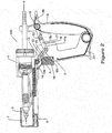
- Is a diagrammatic cross-section side view of an applicator configured as an injector, with the first and second linkages in their over-centre locked positions and the needle shroud in an extended position.
- Figure 1A
- Is a diagrammatic end view of the needle shroud of the injector of
Figure 1 . - Figure 2
- Is a diagrammatic cross-section side view of the injector of
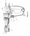
Figure 1 , with the first linkage moved away from the over-centre locked position. - Figure 3
- Is a diagrammatic cross-section side view of the injector of
Figure 1 , with the first linkage in a collapsed position, the needle shroud in the retracted position and the second linkage moved away from the over-centre locked position. - Figure 4
- Is a diagrammatic cross-section side view of the injector of
Figure 1 with both linkages in their collapsed positions, and the handles moved together. - Figure 5
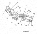
- Is a perspective view of the first and second hinged linkages, both in an over-centre locked position.
- Figure 6
- Is an exploded diagrammatic cross-section side view of the injector of
Figure 1 showing the needle shroud component in position for use in removing the needle from the injector. - Referring first to
Figure 1 , an applicator is shown. The applicator is configured as an injector, generally referenced 100. - The
injector 100 has a body 1 which is provided with afirst handle 2. Thehandle 2 is typically formed as an integral component with the body 1. The body is provided with a cylinder or barrel 3 within which aplunger 3a is reciprocable in order to move fluid from aninlet 4 to anoutlet 5 of theinjector 100. The plunger is actuated by relative movement of thefirst handle 2 towards thesecond handle 6, which causes a remedy in the barrel 3 to move through theoutlet 5 and hence through aneedle 7 which is attached to theoutlet 5. - A
needle shroud 8 is connected to the body 1 so as to be slideable between the extended position shown inFigure 1 , and the retracted position shown inFigures 3 and4 . Theneedle shroud 8 is preferably biased towards the extended position by a suitable biasing means such as aspring 9 positioned between theneedle shroud 8 and the body 1. - In order to reduce the risk of a user accidentally injuring themselves on the
needle 7, a mechanism is provided to lock theneedle shroud 8 in the extended position when theinjector 100 is not in use. - A
linkage 10 is rotatably connected to theneedle shroud 8 at afirst end 11 and to thefirst handle 2 at asecond end 12. Thelinkage 10 is provided with ahinge 13 between the first and second ends which divides the linkage into afirst segment 10a connected to theshroud 8 and asecond segment 10b connected to thefirst handle 2. - With the
needle shroud 8 in the extended position, a biasing means such as atorsion spring 14 biases thelinkage 10 towards an over-centre locked position, as illustrated inFigure 1 . Any suitable means of locking the linkage when it is in this position may be used, but in an example thefirst segment 10a of thelinkage 10 is provided with astop portion 15, best seen inFigure 2 . Thestop portion 15 engages a portion of thesecond segment 10b and prevents thehinge 13 from rotating so as to move thehinge 13 any further away from a notional axis A which extends between the centres of the rotatable connections at the first and second ends of thelinkage 10. With thelinkage 10 in the over-centre locked position thelinkage 10 acts as a substantially rigid strut when subject to a force aligned with the notional axis A. Thelinkage 10 therefore prevents theneedle shroud 8 from moving away from its extended position when in the over-centre locked position. - When the user requires the
needle shroud 8 to be moved to the retracted position, a linkage unlocking means moves thelinkage 10 against the action of the biasing means 14 so that thehinge 13 is on the opposite side of the notional axis A, as shown inFigure 2 . In an example the linkage unlocking means is atrigger 16 which is slideably connected to thefirst handle 2 and is positioned so as to move into engagement with thelinkage 10 when operated by the user, thereby moving thehinge 13 away from the locked position. However, other suitable means of moving thelinkage 10 away from the over-centre locked position will be apparent to those skilled in the art. - With the
linkage 10 in the position shown inFigure 2 theneedle shroud 8 can be retracted to the position shown inFigure 3 , for example as theneedle 7 is inserted into the subject animal. - Referring next to
Figures 1 and2 , in an example a second hingedlinkage 17 is provided between thefirst handle 2 andsecond handle 6. Thesecond linkage 17 is rotatably connected at afirst end 18 to thefirst handle 2 and at a second,opposite end 19 to thesecond handle 6. - The
second linkage 17 is biased towards the over-centre locked position shown inFigures 1 and2 by a suitable biasing means such as atorsion spring 20. Afirst segment 17a of thesecond linkage 17 is provided with astop portion 21 which engages a suitable portion of asecond segment 17b of thelinkage 17, and prevents thehinge 22 from rotating so as to move thehinge 22 any further away from a notional axis B which extends between the centres of the rotatable connections at the first and second ends of thelinkage 17. With thesecond linkage 17 in the over-centre locked position shown inFigures 1 and2 thesecond linkage 17 is substantially rigid to forces aligned with axis B, and thefirst handle 2 andsecond handle 6 cannot be moved together. In this way the chances of accidental dispensing of the remedy are greatly reduced. - In order to unlock the
handles needle shroud 8 must be moved to the fully retracted position shown inFigure 3 . When theneedle shroud 8 reaches the fully retracted position a second linkage unlocking portion of thefirst linkage 10, for example thestop portion 15, engages thesecond linkage 17 and moves it from the over-centre locked position shown inFigures 1 and2 , to the unlocked position shown inFigure 3 . - The
first linkage 10 andsecond linkage 17 may have a pivot axis in common, as seen in the figures. This is not essential, but it does assist in positioning thelinkages first linkage 10 can be used to unlock thesecond linkage 17 when thefirst linkage 10 moves to the collapsed position. - With the
second linkage 17 in the unlocked position thehandles Figure 4 , thereby delivering a dose of the remedy. A dosage control means may be provided to allow adjustment of the dose delivered. A suitable dosage control means is described in the applicant's New Zealand patent No.521084 - Once the dose or remedy has been delivered, the
needle 7 is withdrawn from the animal and thehandles torsion spring 23, thereby drawing a new dose of the remedy from a suitable source through theinlet 4 and into the barrel 3. Biasing means 9 move theneedle shroud 8 back to the extended position, and biasing means 14 and 20 move thelinkages injector 100 is therefore reset and ready to dispense a further dose. - In some examples the over-centre action of the
linkage 17 may mean that thelinkage 17 determines the position of the plunger when in the reset position, rather than the plunger returning to a hard stop. This may lead to small deviations in the dose delivered by the applicator. To prevent this, in an example the connection between theend 19 of thesecond linkage 17 and thesecond handle 6 may allow a small amount of relative movement. In some examples an additional linkage (not shown) may be provided between theend 19 and thesecond handle 6 to allow for this movement. - A more preferred method of allowing relative movement is described with reference to the example of the first and second linkages shown in
Figure 5 , with similar reference numerals indicating similar features as in the other figures. In this example theend 19 of thesecond linkage 17 is provided with an elongate or slottedaperture 26 within which apin 27 is provided. Thepin 27 is connected to the second handle. The elongate or slottedaperture 26 allows a small amount of sliding movement between handle and thesecond linkage 17 in addition to allowing rotational movement. Other variations of this system will be apparent to those skilled in the art. For example thesecond linkage 17 may be provided with projecting pins or similar (not shown) which engage with slots provided in the second handle. In some examples a similar system may be used at the opposite end of the second linkage. In other examples the aperture may simply be oversized relative to the pin, rather than slotted. - In the example of the linkages shown in
Figure 5 , thestop portion 15 is connected to thesecond segment 10b of thefirst linkage 10, rather than to thefirst segment 10a as shown in the examples shown inFigures 1-4 . In the example shown inFigure 5 , thesecond segment 10b of the first linkage is provided with means to unlock the second segment which includes at least oneabutment portion 28 which abuts anabutment portion 29 provided on thefirst segment 17a of thesecond linkage 17 when thefirst linkage 10 is collapsed. This abutment causes thesecond linkage 17 to move away from its over-centre locked position to its collapsed position. - While an example has been described with reference to an example in which the dose is applied by squeezing the
handles - Those skilled in the art will appreciate that in an alternative example of the injector (not shown) the
first linkage 10 may be omitted, and some other means of locking the needle shroud may be provided, if required. In these examples thesecond linkage 17 may be unlocked by some other suitable means such as, for example, a trigger. This method of locking the flow control means may also be used with dispensing means other than injectors, for example pour on applicators and the like. - In a further example (not shown) the applicator may be provided with the
first linkage 10, but thesecond linkage 17 may be omitted. This configuration may be useful where the applicator has a particularly delicate application means, such as a needle or a delicate nozzle, but where the remedy being dispensed is not harmful to humans. - Referring next to
Figures 1, 1 a and in particularFigure 6 , in a preferred embodiment theneedle shroud 8 is provided with means for assisting with the removal of theneedle 7. - In this embodiment the
needle shroud 8 is detachable from the body of theinjector 100. In addition to theaperture 24 in the body 25 of theshroud 8, through which theneedle 7 can extend when theshroud 8 is attached to theinjector 100, theshroud 8 is also provided with acavity 30 shaped and dimensioned to receive theneedle 7 when the user wishes to remove theneedle 7 from theinjector 100. - The
cavity 30 has aformation 31, best seen inFigure 1A , preferably provided at or adjacent themouth 32 of thecavity 30, which is shaped and dimensioned to engage acomplementary formation 33 of theneedle 7. In a preferred embodiment the formation may be a square drive formation as shown inFigure 1A . - The provision of the
cavity 30 andformation 31 allows the point of theneedle 7 to covered when theneedle 7 is removed from theinjector 100. Thecavity mouth 32 may be provided at either end of the body of theshroud 8. In some embodiments (not shown) the cavity may extend through the body of theshroud 8, but it is preferred that the cavity is shaped so that theneedle point 34 can not protrude from thecavity 30. - Some needles for use with such injectors are supplied in a two-part plastic sheath (not shown). One part of the sheath has a socket for the needle hub and the needle sits into the socket with the needle cannula protruding into the sheath so that the sharp end of needle is protected. The sheath can be held and used as a tool to attach the needle to the luer lock of an injector.
- The
aperture 24 in theneedle shroud 8 of the present invention is preferably dimensioned to allow such a sheath to be inserted through the front of the shroud so that the needles can be fitted and removed without having to remove theshroud 8 from theinjector 100. - Those skilled in the art will appreciate that the
needle shroud 8 described above may be used with other injectors of the prior art, but when used in association with theinjector 100 described above there is provided an injector which allows a user to inject a remedy into an animal, and to change a needle of the injector, with minimal risk of needle stick or of accidental delivery of the remedy into the user. - While the applicator shown in the figures is adapted for use with a remote supply of remedy, for example from a backpack, those skilled in the art will appreciate that the invention may also be used with applicators which are provided with a bottle mount on which a bottle containing the remedy may be mounted. Still other examples may be loaded with a cartridge or vial.
- Although this invention has been described by way of example and with reference to possible embodiments thereof, it is to be understood that modifications or improvements may be made thereto without departing from the scope of the appended claims.
Claims (4)
- A needle shroud (8) for an injector (100), the needle shroud (8) including a body (25) provided with: connecting means for releasable connection to the injector (100) when in a first mode of operation, the body (25) having an aperture (24) therethrough shaped and dimensioned to allow a needle (7) to extend through the body (25) when the needle shroud (8) is connected to the injector (100) in the first mode of operation; and a cavity (30) shaped and dimensioned to receive the needle (7) when in use in a second mode of operation, the cavity (30) including a formation (31) shaped and dimensioned to be engageable with a complementary formation (33) of the needle (7) when the needle (7) has been received in the cavity (30), so that rotation of the needle shroud (8) causes rotation of the needle (7), thereby allowing disengagement of the needle (7) from the injector (100) whilst the needle (7) is housed in the cavity (30), characterised in that the aperture (24) and the cavity (30) are both provided adjacent one another in the same face of the body (25) of the shroud (8).
- The needle shroud (8) of claim 1 wherein the cavity (30) is shaped such that a point of the needle (7) does not protrude from the cavity (30) when in use in the second mode of operation.
- The needle shroud (8) of claim 1 or 2, wherein the formation (31) is adapted to receive a square drive needle.
- The needle shroud (8) of any one of the preceding claims, wherein the formation (31) is provided at or adjacent a mouth (32) of the cavity (30).
Applications Claiming Priority (3)
| Application Number | Priority Date | Filing Date | Title |
|---|---|---|---|
| NZ555327A NZ555327A (en) | 2007-05-21 | 2007-05-21 | An applicator which has a two stage interlock that protects from æneedle stickÆ injuries by covering the needle with a shield which also needs to be retracted before a dose can be administered |
| PCT/NZ2008/000113 WO2008143529A2 (en) | 2007-05-21 | 2008-05-21 | Applicator |
| EP08766962.8A EP2152193B1 (en) | 2007-05-21 | 2008-05-21 | Applicator |
Related Parent Applications (2)
| Application Number | Title | Priority Date | Filing Date |
|---|---|---|---|
| EP08766962.8A Division EP2152193B1 (en) | 2007-05-21 | 2008-05-21 | Applicator |
| EP08766962.8A Division-Into EP2152193B1 (en) | 2007-05-21 | 2008-05-21 | Applicator |
Publications (2)
| Publication Number | Publication Date |
|---|---|
| EP3266413A1 EP3266413A1 (en) | 2018-01-10 |
| EP3266413B1 true EP3266413B1 (en) | 2019-12-18 |
Family
ID=40032297
Family Applications (2)
| Application Number | Title | Priority Date | Filing Date |
|---|---|---|---|
| EP17187344.1A Active EP3266413B1 (en) | 2007-05-21 | 2008-05-21 | Needle shroud |
| EP08766962.8A Active EP2152193B1 (en) | 2007-05-21 | 2008-05-21 | Applicator |
Family Applications After (1)
| Application Number | Title | Priority Date | Filing Date |
|---|---|---|---|
| EP08766962.8A Active EP2152193B1 (en) | 2007-05-21 | 2008-05-21 | Applicator |
Country Status (13)
| Country | Link |
|---|---|
| US (1) | US8641682B2 (en) |
| EP (2) | EP3266413B1 (en) |
| JP (1) | JP5399380B2 (en) |
| CN (1) | CN101765413B (en) |
| AU (1) | AU2008253832B2 (en) |
| BR (1) | BRPI0811897B1 (en) |
| CA (1) | CA2694239C (en) |
| ES (1) | ES2656796T3 (en) |
| MX (1) | MX2009012605A (en) |
| NZ (1) | NZ555327A (en) |
| RU (1) | RU2009147274A (en) |
| WO (1) | WO2008143529A2 (en) |
| ZA (1) | ZA200909137B (en) |
Families Citing this family (15)
| Publication number | Priority date | Publication date | Assignee | Title |
|---|---|---|---|---|
| US8366679B2 (en) * | 2009-04-16 | 2013-02-05 | Cole Isolation Technique, Llc | Self filling injection device |
| US9232990B2 (en) | 2009-05-28 | 2016-01-12 | Simcro Limited | Skin gripping means, injector including the skin gripping means and method of performing a subcutaneous injection |
| CH705153A1 (en) * | 2011-06-24 | 2012-12-31 | Heidi Hall | Mors and system to send a viscous substance and / or liquid into the mouth of an animal. |
| CA153896S (en) * | 2013-07-17 | 2014-08-06 | Henke Sass Wolf Gmbh | Injector |
| CN104771244B (en) * | 2014-01-13 | 2017-10-27 | 中国农业科学院饲料研究所 | A kind of animal injection device |
| KR101636299B1 (en) * | 2015-04-02 | 2016-07-05 | 김광현 | Meso therapie apparatus |
| US10342742B2 (en) * | 2015-04-07 | 2019-07-09 | Kenneth Edward Ruda | Bolus feeding device |
| CN107397606B (en) * | 2017-08-28 | 2019-01-22 | 信阳农林学院 | A kind of veterinary syringe |
| CN107737390A (en) * | 2017-11-29 | 2018-02-27 | 林融纲 | A kind of fat injection rifle |
| WO2019235942A1 (en) | 2018-06-06 | 2019-12-12 | Simcro Limited | Improvements in, or relating to, applicators |
| CN110051453B (en) * | 2019-05-31 | 2024-04-16 | 广西壮族自治区畜牧研究所 | Intradermal injection device for animals and injection aid therefor |
| CN110339430A (en) * | 2019-08-15 | 2019-10-18 | 北京天悦生科技有限公司 | One kind can the continuous veterinary drug syringe of making type |
| CN112220582A (en) * | 2020-10-27 | 2021-01-15 | 青海省大通种牛场 | Quick injection gun |
| CN112641499A (en) * | 2020-12-31 | 2021-04-13 | 杭州堃博生物科技有限公司 | Pusher and steam ablation equipment |
| CN113331980B (en) * | 2021-05-10 | 2024-02-23 | 武汉市正华精机技术发展有限公司 | Needleless injector for animals |
Family Cites Families (31)
| Publication number | Priority date | Publication date | Assignee | Title |
|---|---|---|---|---|
| US2624338A (en) * | 1950-10-31 | 1953-01-06 | Frank C Moore | Dispensing gun |
| US3261243A (en) | 1964-09-18 | 1966-07-19 | Wallace D Ellison | Toggle clamp having a lock mechanism engageable as an over-center position is approached |
| US3517668A (en) * | 1967-10-16 | 1970-06-30 | Bio Neering Inc | Multiple dosage veterinary injection gun |
| IT969196B (en) * | 1972-11-25 | 1974-03-30 | Colombo A | DEVICE FOR DENTAL USE SPECIFICALLY SUITABLE FOR INTRALIGAMENTARY ANESTHESIA |
| US4020838A (en) * | 1975-05-06 | 1977-05-03 | N.J. Phillips Pty. Limited | Animal dosing syringe |
| GB1565692A (en) * | 1976-03-02 | 1980-04-23 | Wellcome Found | Luquid dispensing device |
| US4318559A (en) * | 1980-03-31 | 1982-03-09 | Johnston & Margolis, P.C. | Lock for sliding members |
| AU572322B2 (en) * | 1984-07-27 | 1988-05-05 | N.J. Phillips Pty. Limited | Tape dispenser |
| NZ212899A (en) * | 1984-07-31 | 1987-10-30 | Phillips Pty Ltd N J | Piston operated adjustable volume dose injector for animals |
| US4695274A (en) * | 1986-01-31 | 1987-09-22 | Fox Richard L | Protected hypodermic needle |
| US4772272A (en) * | 1987-05-11 | 1988-09-20 | Mcfarland Barton C | Needle protective sleeve |
| CN88200415U (en) * | 1988-01-22 | 1988-12-14 | 张寂勇 | Successive injection syringe with counter |
| US4850996A (en) * | 1988-02-22 | 1989-07-25 | Cree Ian C | Safety needle |
| US4911693A (en) * | 1988-10-17 | 1990-03-27 | Paris Frassetti R | Hypodermic syringe needle guard |
| US4946446A (en) * | 1989-06-14 | 1990-08-07 | Vadher Dinesh L | Retractable needle |
| US5049136A (en) * | 1990-01-10 | 1991-09-17 | Johnson Gerald W | Hypodermic needle with protective sheath |
| CN2085228U (en) * | 1991-03-15 | 1991-09-25 | 靳贵 | Continuous all-metal injector for animal |
| FR2693112B1 (en) * | 1992-07-01 | 1994-09-02 | Raymond Denance | Electromechanical injection device for medical and veterinary use actuated by a trigger. |
| GB2288539B (en) * | 1994-04-21 | 1998-04-15 | Genesis Mfg Ltd | Device for injecting a substance into the body of an animal |
| AUPO742497A0 (en) * | 1997-06-18 | 1997-07-10 | N.J. Phillips Pty. Limited | An applicator |
| AUPO889497A0 (en) * | 1997-09-01 | 1997-09-25 | N.J. Phillips Pty. Limited | An applicator |
| CN1193804C (en) * | 1998-09-23 | 2005-03-23 | L·R·科赫 | Needle point guard safety cap assembly |
| US6460787B1 (en) | 1998-10-22 | 2002-10-08 | Nordson Corporation | Modular fluid spray gun |
| JP2001170090A (en) | 1999-12-20 | 2001-06-26 | Fujihira Industry Co Ltd | Syringe for creature |
| GB0214452D0 (en) | 2002-06-22 | 2002-07-31 | Liversidge Barry P | Medical needle assemblies |
| NZ521084A (en) | 2002-08-28 | 2005-01-28 | Simcro Tech Ltd | Selectable dosage dispensing apparatus |
| NZ524938A (en) * | 2003-03-24 | 2005-10-28 | Simcro Tech Ltd | Dispenser, for treating animals, with damping to avoid shock waves |
| CA2539156C (en) * | 2003-09-22 | 2012-12-11 | Smiths Medical Asd, Inc. | Safety needle assembly and method for making the same |
| US20050137575A1 (en) * | 2003-12-18 | 2005-06-23 | Duke University | Minimally invasive injection devices and methods |
| GB0517699D0 (en) * | 2005-09-01 | 2005-10-05 | Owen Mumford Ltd | Needle shroud assembly |
| AU2006228045B2 (en) * | 2005-10-14 | 2011-11-24 | Covidien Lp | Apparatus for laparoscopic or endoscopic procedures |
-
2007
- 2007-05-21 NZ NZ555327A patent/NZ555327A/en unknown
-
2008
- 2008-05-21 CN CN2008800231691A patent/CN101765413B/en active Active
- 2008-05-21 CA CA2694239A patent/CA2694239C/en active Active
- 2008-05-21 EP EP17187344.1A patent/EP3266413B1/en active Active
- 2008-05-21 AU AU2008253832A patent/AU2008253832B2/en active Active
- 2008-05-21 WO PCT/NZ2008/000113 patent/WO2008143529A2/en active Application Filing
- 2008-05-21 RU RU2009147274/21A patent/RU2009147274A/en not_active Application Discontinuation
- 2008-05-21 EP EP08766962.8A patent/EP2152193B1/en active Active
- 2008-05-21 JP JP2010509292A patent/JP5399380B2/en active Active
- 2008-05-21 MX MX2009012605A patent/MX2009012605A/en active IP Right Grant
- 2008-05-21 US US12/451,566 patent/US8641682B2/en active Active
- 2008-05-21 ES ES08766962.8T patent/ES2656796T3/en active Active
- 2008-05-21 BR BRPI0811897-3A patent/BRPI0811897B1/en active IP Right Grant
-
2009
- 2009-12-21 ZA ZA2009/09137A patent/ZA200909137B/en unknown
Non-Patent Citations (1)
| Title |
|---|
| None * |
Also Published As
| Publication number | Publication date |
|---|---|
| CA2694239C (en) | 2014-09-16 |
| EP2152193A4 (en) | 2016-09-28 |
| EP2152193A2 (en) | 2010-02-17 |
| RU2009147274A (en) | 2011-06-27 |
| WO2008143529A2 (en) | 2008-11-27 |
| ZA200909137B (en) | 2014-05-28 |
| AU2008253832B2 (en) | 2013-08-29 |
| CN101765413B (en) | 2011-06-15 |
| AU2008253832A1 (en) | 2008-11-27 |
| CN101765413A (en) | 2010-06-30 |
| EP3266413A1 (en) | 2018-01-10 |
| JP5399380B2 (en) | 2014-01-29 |
| BRPI0811897B1 (en) | 2019-07-30 |
| MX2009012605A (en) | 2010-03-08 |
| JP2010527686A (en) | 2010-08-19 |
| BRPI0811897A2 (en) | 2014-11-18 |
| US20100145283A1 (en) | 2010-06-10 |
| WO2008143529A3 (en) | 2009-01-15 |
| NZ555327A (en) | 2009-09-25 |
| EP2152193B1 (en) | 2017-11-15 |
| US8641682B2 (en) | 2014-02-04 |
| ES2656796T3 (en) | 2018-02-28 |
| CA2694239A1 (en) | 2008-11-27 |
Similar Documents
| Publication | Publication Date | Title |
|---|---|---|
| EP3266413B1 (en) | Needle shroud | |
| JP6871216B2 (en) | Automatic injector for injectable cartridges and drive control mechanism for it | |
| KR101590658B1 (en) | Veterinary syringe for multiple injections | |
| JP5718224B2 (en) | Self-injector with filling means | |
| DK2654836T3 (en) | autoinjector | |
| US7749201B2 (en) | Device for administering an injectable product with a lockable dose metering mechanism | |
| CZ294265B6 (en) | Injection device and method for its operation | |
| HUE028698T2 (en) | Automatic injector | |
| MXPA01011493A (en) | Injection device and method for its operation. | |
| CA2790188A1 (en) | Auto-injector | |
| HUE025404T2 (en) | Auto-injector | |
| WO2006135615A2 (en) | Exchangeable safety needle assembly | |
| WO2006079898A1 (en) | Injection device for administering a medication liquid | |
| EP2285438B1 (en) | Medicament delivery device | |
| US20090082753A1 (en) | Needle free injector with dose adjustment assembly | |
| NZ577306A (en) | Injector needle shroud |
Legal Events
| Date | Code | Title | Description |
|---|---|---|---|
| PUAI | Public reference made under article 153(3) epc to a published international application that has entered the european phase |
Free format text: ORIGINAL CODE: 0009012 |
|
| STAA | Information on the status of an ep patent application or granted ep patent |
Free format text: STATUS: THE APPLICATION HAS BEEN PUBLISHED |
|
| AC | Divisional application: reference to earlier application |
Ref document number: 2152193 Country of ref document: EP Kind code of ref document: P |
|
| AK | Designated contracting states |
Kind code of ref document: A1 Designated state(s): AT BE BG CH CY CZ DE DK EE ES FI FR GB GR HR HU IE IS IT LI LT LU LV MC MT NL NO PL PT RO SE SI SK TR |
|
| STAA | Information on the status of an ep patent application or granted ep patent |
Free format text: STATUS: REQUEST FOR EXAMINATION WAS MADE |
|
| 17P | Request for examination filed |
Effective date: 20180618 |
|
| RBV | Designated contracting states (corrected) |
Designated state(s): AT BE BG CH CY CZ DE DK EE ES FI FR GB GR HR HU IE IS IT LI LT LU LV MC MT NL NO PL PT RO SE SI SK TR |
|
| GRAP | Despatch of communication of intention to grant a patent |
Free format text: ORIGINAL CODE: EPIDOSNIGR1 |
|
| STAA | Information on the status of an ep patent application or granted ep patent |
Free format text: STATUS: GRANT OF PATENT IS INTENDED |
|
| RIC1 | Information provided on ipc code assigned before grant |
Ipc: A61M 35/00 20060101ALI20190620BHEP Ipc: A61M 5/178 20060101ALI20190620BHEP Ipc: A61D 7/00 20060101AFI20190620BHEP |
|
| INTG | Intention to grant announced |
Effective date: 20190723 |
|
| GRAS | Grant fee paid |
Free format text: ORIGINAL CODE: EPIDOSNIGR3 |
|
| GRAA | (expected) grant |
Free format text: ORIGINAL CODE: 0009210 |
|
| STAA | Information on the status of an ep patent application or granted ep patent |
Free format text: STATUS: THE PATENT HAS BEEN GRANTED |
|
| AC | Divisional application: reference to earlier application |
Ref document number: 2152193 Country of ref document: EP Kind code of ref document: P |
|
| AK | Designated contracting states |
Kind code of ref document: B1 Designated state(s): AT BE BG CH CY CZ DE DK EE ES FI FR GB GR HR HU IE IS IT LI LT LU LV MC MT NL NO PL PT RO SE SI SK TR |
|
| REG | Reference to a national code |
Ref country code: CH Ref legal event code: EP |
|
| REG | Reference to a national code |
Ref country code: IE Ref legal event code: FG4D |
|
| REG | Reference to a national code |
Ref country code: DE Ref legal event code: R096 Ref document number: 602008061862 Country of ref document: DE |
|
| REG | Reference to a national code |
Ref country code: AT Ref legal event code: REF Ref document number: 1213734 Country of ref document: AT Kind code of ref document: T Effective date: 20200115 |
|
| REG | Reference to a national code |
Ref country code: NL Ref legal event code: MP Effective date: 20191218 |
|
| PG25 | Lapsed in a contracting state [announced via postgrant information from national office to epo] |
Ref country code: LV Free format text: LAPSE BECAUSE OF FAILURE TO SUBMIT A TRANSLATION OF THE DESCRIPTION OR TO PAY THE FEE WITHIN THE PRESCRIBED TIME-LIMIT Effective date: 20191218 Ref country code: SE Free format text: LAPSE BECAUSE OF FAILURE TO SUBMIT A TRANSLATION OF THE DESCRIPTION OR TO PAY THE FEE WITHIN THE PRESCRIBED TIME-LIMIT Effective date: 20191218 Ref country code: LT Free format text: LAPSE BECAUSE OF FAILURE TO SUBMIT A TRANSLATION OF THE DESCRIPTION OR TO PAY THE FEE WITHIN THE PRESCRIBED TIME-LIMIT Effective date: 20191218 Ref country code: FI Free format text: LAPSE BECAUSE OF FAILURE TO SUBMIT A TRANSLATION OF THE DESCRIPTION OR TO PAY THE FEE WITHIN THE PRESCRIBED TIME-LIMIT Effective date: 20191218 Ref country code: BG Free format text: LAPSE BECAUSE OF FAILURE TO SUBMIT A TRANSLATION OF THE DESCRIPTION OR TO PAY THE FEE WITHIN THE PRESCRIBED TIME-LIMIT Effective date: 20200318 Ref country code: NO Free format text: LAPSE BECAUSE OF FAILURE TO SUBMIT A TRANSLATION OF THE DESCRIPTION OR TO PAY THE FEE WITHIN THE PRESCRIBED TIME-LIMIT Effective date: 20200318 Ref country code: GR Free format text: LAPSE BECAUSE OF FAILURE TO SUBMIT A TRANSLATION OF THE DESCRIPTION OR TO PAY THE FEE WITHIN THE PRESCRIBED TIME-LIMIT Effective date: 20200319 |
|
| REG | Reference to a national code |
Ref country code: LT Ref legal event code: MG4D |
|
| PG25 | Lapsed in a contracting state [announced via postgrant information from national office to epo] |
Ref country code: HR Free format text: LAPSE BECAUSE OF FAILURE TO SUBMIT A TRANSLATION OF THE DESCRIPTION OR TO PAY THE FEE WITHIN THE PRESCRIBED TIME-LIMIT Effective date: 20191218 |
|
| PG25 | Lapsed in a contracting state [announced via postgrant information from national office to epo] |
Ref country code: CZ Free format text: LAPSE BECAUSE OF FAILURE TO SUBMIT A TRANSLATION OF THE DESCRIPTION OR TO PAY THE FEE WITHIN THE PRESCRIBED TIME-LIMIT Effective date: 20191218 Ref country code: PT Free format text: LAPSE BECAUSE OF FAILURE TO SUBMIT A TRANSLATION OF THE DESCRIPTION OR TO PAY THE FEE WITHIN THE PRESCRIBED TIME-LIMIT Effective date: 20200513 Ref country code: RO Free format text: LAPSE BECAUSE OF FAILURE TO SUBMIT A TRANSLATION OF THE DESCRIPTION OR TO PAY THE FEE WITHIN THE PRESCRIBED TIME-LIMIT Effective date: 20191218 Ref country code: NL Free format text: LAPSE BECAUSE OF FAILURE TO SUBMIT A TRANSLATION OF THE DESCRIPTION OR TO PAY THE FEE WITHIN THE PRESCRIBED TIME-LIMIT Effective date: 20191218 Ref country code: EE Free format text: LAPSE BECAUSE OF FAILURE TO SUBMIT A TRANSLATION OF THE DESCRIPTION OR TO PAY THE FEE WITHIN THE PRESCRIBED TIME-LIMIT Effective date: 20191218 |
|
| PG25 | Lapsed in a contracting state [announced via postgrant information from national office to epo] |
Ref country code: IS Free format text: LAPSE BECAUSE OF FAILURE TO SUBMIT A TRANSLATION OF THE DESCRIPTION OR TO PAY THE FEE WITHIN THE PRESCRIBED TIME-LIMIT Effective date: 20200418 Ref country code: SK Free format text: LAPSE BECAUSE OF FAILURE TO SUBMIT A TRANSLATION OF THE DESCRIPTION OR TO PAY THE FEE WITHIN THE PRESCRIBED TIME-LIMIT Effective date: 20191218 |
|
| REG | Reference to a national code |
Ref country code: DE Ref legal event code: R097 Ref document number: 602008061862 Country of ref document: DE |
|
| REG | Reference to a national code |
Ref country code: AT Ref legal event code: MK05 Ref document number: 1213734 Country of ref document: AT Kind code of ref document: T Effective date: 20191218 |
|
| PLBE | No opposition filed within time limit |
Free format text: ORIGINAL CODE: 0009261 |
|
| STAA | Information on the status of an ep patent application or granted ep patent |
Free format text: STATUS: NO OPPOSITION FILED WITHIN TIME LIMIT |
|
| PG25 | Lapsed in a contracting state [announced via postgrant information from national office to epo] |
Ref country code: ES Free format text: LAPSE BECAUSE OF FAILURE TO SUBMIT A TRANSLATION OF THE DESCRIPTION OR TO PAY THE FEE WITHIN THE PRESCRIBED TIME-LIMIT Effective date: 20191218 Ref country code: DK Free format text: LAPSE BECAUSE OF FAILURE TO SUBMIT A TRANSLATION OF THE DESCRIPTION OR TO PAY THE FEE WITHIN THE PRESCRIBED TIME-LIMIT Effective date: 20191218 |
|
| 26N | No opposition filed |
Effective date: 20200921 |
|
| PG25 | Lapsed in a contracting state [announced via postgrant information from national office to epo] |
Ref country code: AT Free format text: LAPSE BECAUSE OF FAILURE TO SUBMIT A TRANSLATION OF THE DESCRIPTION OR TO PAY THE FEE WITHIN THE PRESCRIBED TIME-LIMIT Effective date: 20191218 Ref country code: SI Free format text: LAPSE BECAUSE OF FAILURE TO SUBMIT A TRANSLATION OF THE DESCRIPTION OR TO PAY THE FEE WITHIN THE PRESCRIBED TIME-LIMIT Effective date: 20191218 |
|
| REG | Reference to a national code |
Ref country code: DE Ref legal event code: R119 Ref document number: 602008061862 Country of ref document: DE |
|
| PG25 | Lapsed in a contracting state [announced via postgrant information from national office to epo] |
Ref country code: IT Free format text: LAPSE BECAUSE OF FAILURE TO SUBMIT A TRANSLATION OF THE DESCRIPTION OR TO PAY THE FEE WITHIN THE PRESCRIBED TIME-LIMIT Effective date: 20191218 Ref country code: LI Free format text: LAPSE BECAUSE OF NON-PAYMENT OF DUE FEES Effective date: 20200531 Ref country code: MC Free format text: LAPSE BECAUSE OF FAILURE TO SUBMIT A TRANSLATION OF THE DESCRIPTION OR TO PAY THE FEE WITHIN THE PRESCRIBED TIME-LIMIT Effective date: 20191218 Ref country code: CH Free format text: LAPSE BECAUSE OF NON-PAYMENT OF DUE FEES Effective date: 20200531 |
|
| PG25 | Lapsed in a contracting state [announced via postgrant information from national office to epo] |
Ref country code: PL Free format text: LAPSE BECAUSE OF FAILURE TO SUBMIT A TRANSLATION OF THE DESCRIPTION OR TO PAY THE FEE WITHIN THE PRESCRIBED TIME-LIMIT Effective date: 20191218 |
|
| REG | Reference to a national code |
Ref country code: BE Ref legal event code: MM Effective date: 20200531 |
|
| GBPC | Gb: european patent ceased through non-payment of renewal fee |
Effective date: 20200521 |
|
| PG25 | Lapsed in a contracting state [announced via postgrant information from national office to epo] |
Ref country code: LU Free format text: LAPSE BECAUSE OF NON-PAYMENT OF DUE FEES Effective date: 20200521 |
|
| PG25 | Lapsed in a contracting state [announced via postgrant information from national office to epo] |
Ref country code: IE Free format text: LAPSE BECAUSE OF NON-PAYMENT OF DUE FEES Effective date: 20200521 Ref country code: GB Free format text: LAPSE BECAUSE OF NON-PAYMENT OF DUE FEES Effective date: 20200521 Ref country code: FR Free format text: LAPSE BECAUSE OF NON-PAYMENT OF DUE FEES Effective date: 20200531 |
|
| PG25 | Lapsed in a contracting state [announced via postgrant information from national office to epo] |
Ref country code: BE Free format text: LAPSE BECAUSE OF NON-PAYMENT OF DUE FEES Effective date: 20200531 Ref country code: DE Free format text: LAPSE BECAUSE OF NON-PAYMENT OF DUE FEES Effective date: 20201201 |
|
| PG25 | Lapsed in a contracting state [announced via postgrant information from national office to epo] |
Ref country code: TR Free format text: LAPSE BECAUSE OF FAILURE TO SUBMIT A TRANSLATION OF THE DESCRIPTION OR TO PAY THE FEE WITHIN THE PRESCRIBED TIME-LIMIT Effective date: 20191218 Ref country code: MT Free format text: LAPSE BECAUSE OF FAILURE TO SUBMIT A TRANSLATION OF THE DESCRIPTION OR TO PAY THE FEE WITHIN THE PRESCRIBED TIME-LIMIT Effective date: 20191218 Ref country code: CY Free format text: LAPSE BECAUSE OF FAILURE TO SUBMIT A TRANSLATION OF THE DESCRIPTION OR TO PAY THE FEE WITHIN THE PRESCRIBED TIME-LIMIT Effective date: 20191218 |