EP2151630B1 - Dispositif de tourbillonnement - Google Patents
Dispositif de tourbillonnement Download PDFInfo
- Publication number
- EP2151630B1 EP2151630B1 EP08013950A EP08013950A EP2151630B1 EP 2151630 B1 EP2151630 B1 EP 2151630B1 EP 08013950 A EP08013950 A EP 08013950A EP 08013950 A EP08013950 A EP 08013950A EP 2151630 B1 EP2151630 B1 EP 2151630B1
- Authority
- EP
- European Patent Office
- Prior art keywords
- swirler
- hub
- fuel
- boundary wall
- air
- Prior art date
- Legal status (The legal status is an assumption and is not a legal conclusion. Google has not performed a legal analysis and makes no representation as to the accuracy of the status listed.)
- Not-in-force
Links
Images

Classifications
-
- F—MECHANICAL ENGINEERING; LIGHTING; HEATING; WEAPONS; BLASTING
- F23—COMBUSTION APPARATUS; COMBUSTION PROCESSES
- F23R—GENERATING COMBUSTION PRODUCTS OF HIGH PRESSURE OR HIGH VELOCITY, e.g. GAS-TURBINE COMBUSTION CHAMBERS
- F23R3/00—Continuous combustion chambers using liquid or gaseous fuel
- F23R3/02—Continuous combustion chambers using liquid or gaseous fuel characterised by the air-flow or gas-flow configuration
- F23R3/04—Air inlet arrangements
- F23R3/10—Air inlet arrangements for primary air
- F23R3/12—Air inlet arrangements for primary air inducing a vortex
- F23R3/14—Air inlet arrangements for primary air inducing a vortex by using swirl vanes
-
- F—MECHANICAL ENGINEERING; LIGHTING; HEATING; WEAPONS; BLASTING
- F23—COMBUSTION APPARATUS; COMBUSTION PROCESSES
- F23C—METHODS OR APPARATUS FOR COMBUSTION USING FLUID FUEL OR SOLID FUEL SUSPENDED IN A CARRIER GAS OR AIR
- F23C7/00—Combustion apparatus characterised by arrangements for air supply
- F23C7/002—Combustion apparatus characterised by arrangements for air supply the air being submitted to a rotary or spinning motion
- F23C7/004—Combustion apparatus characterised by arrangements for air supply the air being submitted to a rotary or spinning motion using vanes
Definitions
- Gas turbines are known to have the following components: a compressor for compressing air; at least one combustion chamber for generating hot gas by burning fuel in the presence of the compressed air supplied by the compressor; and a turbine in which the hot gas supplied from the combustion chamber is expanded.
- NOx nitrogen oxides
- CO carbon monoxide
- One known factor affecting NOx emissions is the combustion temperature. If the combustion temperature is lowered, the amount of NOx released decreases. However, high combustion temperatures are desirable to achieve high efficiency and enhance CO oxidation. It is known that leaner fuel / air mixtures burn cooler and therefore less NOx emissions arise.
- One known technique for producing a leaner fuel mixture is to create turbulence to mix air and fuel as evenly as possible prior to combustion to avoid creating zones of rich mixture in which there are high temperature localities called hot spots).
- combustion engines in particular those which are operated with two different fuels, for example, an injection of the fuel oil via Swirler, in which the oil is mixed with air.
- Swirler in which the oil is mixed with air.
- These swirlers are usually arranged concentrically around a heavily twisted pilot burner. The pilot is followed by a pilot cone, in which the pilot gas combustion takes place. This, downstream in the flow direction, the main combustion takes place. Combustion air flows through the pilot or the Swirler and is mixed there with fuel. To prevent unwanted ignition of the mixture, the intermediate areas between the swirlers are traversed by air or an air / fuel mixture. This air is available for an improvement of the mixture and / or for a reduction of the maximum combustion temperature only limited.
- the US 2004/0163392 A discloses Swirler, which at the Brenn Kunststoffeingahgsseite have a round cross-section. Downstream of a swirler, the cross section transitions from a circular to a trapezoidal shape.
- the US 5,373,693 A discloses a fuel nozzle coaxially associated with an annular swirl means, the swirl means having tangential channels between circumferentially distributed profiles for controllable supply of combustion air.
- the U 6,038,861 discloses Swirler, which have a round cross section at the combustion air inlet side. These expand with increasing flow direction. Adjacent swirlers eventually join together to form an annular gap. However, this is difficult to implement on the production side.
- a swirler with a hub arranged along an axis and with a boundary wall which completely surrounds the hub and which comprises at least one swirl blade which extends radially outward from the hub to the boundary wall.
- the cross section formed by the boundary wall perpendicular to the axis is trapezoidal.
- the invention has thus recognized that in the current geometry of the Swirler an intensive flow through the intermediate areas with air is inevitable, thus avoiding inflammation of these intermediate areas.
- a trapezoidal cross-section can be integrated into the burner much more simply, in particular two swirlers with respect to one another, so that an inflammation of these intermediate regions can be avoided even without intensive flushing with air.
- Trapezoidal includes all geometries that has essentially two parallel sides. These can also have a slight curvature.
- the corners of the boundary wall can also have a rounding. All sides of the boundary wall may have a slight bend.
- the at least one swirl blade preferably has a 3-d geometry.
- corner blades may be present in the corners of the boundary wall. These can be pointed and directed from the hub to the cross section or vice versa.
- the corner vanes must also not consistently enough from the hub to the cross section. This ensures a better aerodynamic flow through the strongly 3-dimensional flow field.
- the corners of the boundary wall can be protected with effusion air. This avoids a flashback.
- fuel can be passed through the hub.
- fuel injections are arranged. These can be arranged on the swirl blades. During operation, fuel is thus injected into the air or the air / fuel mixture.
- FIG. 1 shows a burner 100 with a nozzle housing 6 and a lower part 5.
- a pilot burner 1 which has an injection opening 4 for the pilot fuel, passes through the nozzle housing 6 and is fixed to the lower part 5 of the nozzle housing.
- the main fuel nozzles 2 are parallel to the pilot burner 1 through the nozzle housing 6 and are fixed to the lower part 5 of the nozzle housing.
- the fuel inlets 16 supply the main fuel nozzles 2 with fuel.
- a main combustion zone 9 is formed within the liner 19.
- a pilot cone 20 protrudes from the vicinity of the pilot fuel injection port 4 of the pilot burner 1 and has a widened end 22 adjacent to the main combustion zone 9.
- the pilot cone 20 has an expanding profile forming a zone 23 for the pilot flame.
- the compressed air 101 flows from the compressor 50 between support ribs 7 through the main air swirling devices 8 into the main combustion zone 9.
- Each main air swirling device 8 is parallel to the pilot burner 1 and adjoins the main combustion zone 9.
- a plurality of swirlers 80 surround each main fuel nozzle 2. These generate a swirl to mix compressed air 101 and fuel 102 together.
- a fuel / air mixture 103 is carried to the main combustion zone where it burns.
- the compressed air 101 also enters zone 23 of the pilot flame through a set of stationary sheets 10 located within pilot rotors 11.
- the compressed air 101 mixes within the pilot cone 20 with the pilot fuel 30 and is transported to the zone 23 of the pilot flame, where it burns.
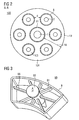
- FIG. 2 shows a view of a combustion chamber 100 along the axes AA.
- the pilot burner 1 of main fuel nozzles 2 is annularly surrounded.
- a main fuel swirling device 8 with swirlers 80 surrounds each main fuel nozzle 2.
- the main fuel nozzles 8 are separated from each other by the distance d.
- the pilot burner 1 is surrounded by main fuel nozzles 2, which are equidistantly spaced, but these distances may also vary.
- the widened end 22 of the pilot cone 20 forms with the liner 19 a circular ring.
- the fuel / air mixture flows through the annulus into the main combustion zone 19.
- gaps In order to prevent an undesired ignition of the mixture between the main fuel nozzles 8, hereinafter referred to as gaps, these spaces of the main fuel nozzles 8 are thoroughly flushed with air. This air is limited for an improvement of the mixture and / or the reduction of the maximum combustion temperature available. Since it is known that leaner mixtures of fuel and air burn cooler and thus reduce the emission of NOx, it is desirable to minimize the required purge air in a simple manner.
- FIG. 3 shows a Swirler 90 in particular for a gas turbine.
- the swirler 90 has a boundary wall (B) which has a cross section formed perpendicular to the axis (A), this cross-section being trapezoidal.
- the Swirler 90 comprises at least one swirl blade 91.
- the swirler 90 is arranged substantially on a central hub 92. Through these takes place, the fuel supply.
- the central hub 92 is connected to a fuel line.
- the swirl blade 91 is preferably formed as a 3-D blade.
- the fuel may be injected from the hub 92 or from the blades. This causes a better aerodynamic flow through the 3-dimensional flow field.
- 3-d blades can be used.
- corner blades 96 can be applied, which taper from the cross-sectional corners. These corner blades 96 are located in the corners of the boundary wall (B) and can reach to the hub 92; but also between the boundary wall (B) and hub 92 end. This achieves a better, more uniform flow behavior. Furthermore, it is advantageous that the corners of the boundary wall (B) are flowed through with effusion air, thus protecting these corners particularly well against flashback.
- the swirl vanes 91 for fuel injection are fixedly connected to the boundary wall (B) of the Swirler 90. Alternatively, the swirl vanes 91 may also be connected only to the hub 92, are suspended as a component only on the hub 92, so to speak. This would be easier to produce in terms of production technology and thus cause lower costs.
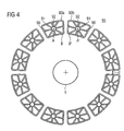
- FIG. 4 schematically shows a Swirleran Aunt 95 comprising the Swirler 90a, 90b. These are arranged centrally and annularly around a pilot burner 1.
- the Swirler 90 a, 90b have a small distance d1 from each other. Due to the trapezoidal geometry of the cross sections, the swirlers can also be set very close to the plane of the pilot cone 20, since the advantageous geometric design precisely joins together the corresponding annular gap contour with segments in the circumferential direction.
- a non-circular Swirler which has a circumferentially segmented flow creates, which is twisted each. Furthermore, it is possible with the aid of the invention to flow through the so-called interstices with substantially less air, so as to avoid unwanted inflammations of the interstices. Thus, more air is available for combustion. Another advantage is the simpler mechanical design and the associated greater robustness and lower production costs.
Landscapes
- Engineering & Computer Science (AREA)
- Chemical & Material Sciences (AREA)
- Combustion & Propulsion (AREA)
- Mechanical Engineering (AREA)
- General Engineering & Computer Science (AREA)
- Pressure-Spray And Ultrasonic-Wave- Spray Burners (AREA)
- Structures Of Non-Positive Displacement Pumps (AREA)
Claims (8)
- Dispositif ( 90 ) de tourbillonnement ayant un moyeu ( 92 ) disposé suivant un axe ( A ) et une paroi ( B ) de délimitation entourant complètement le moyeu ( 92 ) et à distance du moyeu et comprenant au moins une pale ( 91 ) de mise en tourbillonnement, qui s'étend radialement en étant dirigée vers l'extérieur du moyeu ( 92 ) jusqu'à la paroi ( B ) de limitation, caractérisé en ce que la section transversale formée par la paroi ( B ) de limitation perpendiculairement à l'axe ( A ) est trapézoïdale.
- Dispositif ( 90 ) de tourbillonnement suivant la revendication 1,
caractérisé en ce que la au moins une pale ( 91 ) a une géométrie en 3D. - Dispositif ( 90 ) de tourbillonnement suivant l'une des revendications précédentes,
caractérisé en ce qu'il y a des pales ( 96 ) de coin aux coins de la paroi ( B ) de limitation. - Dispositif ( 90 ) de tourbillonnement suivant la revendication 3,
caractérisé en ce que les pales ( 96 ) de coin sont pointues. - Dispositif ( 90 ) de tourbillonnement suivant l'une des revendications précédentes,
caractérisé en ce que du combustible peut passer dans le moyeu ( 92 ). - Dispositif ( 90 ) de tourbillonnement suivant la revendication 5,
caractérisé en ce qu'il est prévu des injections de combustible. - Dispositif ( 90 ) de tourbillonnement suivant l'une des revendications précédentes,
caractérisé en ce que du combustible peut passer par le moyeu ( 92 ) dans les pales ( 91 ) de mise en tourbillonnement et y être projeté et/ou du combustible est projeté supplémentairement à partir du moyeu. - Dispositif ( 90 ) de tourbillonnement suivant l'une des revendications précédentes,
caractérisé en ce que la paroi de limitation et/ou les coins de la paroi ( B ) de limitation sont protégés par de l'air d'effusion.
Priority Applications (3)
| Application Number | Priority Date | Filing Date | Title |
|---|---|---|---|
| AT08013950T ATE528589T1 (de) | 2008-08-04 | 2008-08-04 | Swirler |
| EP08013950A EP2151630B1 (fr) | 2008-08-04 | 2008-08-04 | Dispositif de tourbillonnement |
| JP2009179079A JP5574635B2 (ja) | 2008-08-04 | 2009-07-31 | 旋回翼 |
Applications Claiming Priority (1)
| Application Number | Priority Date | Filing Date | Title |
|---|---|---|---|
| EP08013950A EP2151630B1 (fr) | 2008-08-04 | 2008-08-04 | Dispositif de tourbillonnement |
Publications (2)
| Publication Number | Publication Date |
|---|---|
| EP2151630A1 EP2151630A1 (fr) | 2010-02-10 |
| EP2151630B1 true EP2151630B1 (fr) | 2011-10-12 |
Family
ID=40351605
Family Applications (1)
| Application Number | Title | Priority Date | Filing Date |
|---|---|---|---|
| EP08013950A Not-in-force EP2151630B1 (fr) | 2008-08-04 | 2008-08-04 | Dispositif de tourbillonnement |
Country Status (3)
| Country | Link |
|---|---|
| EP (1) | EP2151630B1 (fr) |
| JP (1) | JP5574635B2 (fr) |
| AT (1) | ATE528589T1 (fr) |
Families Citing this family (3)
| Publication number | Priority date | Publication date | Assignee | Title |
|---|---|---|---|---|
| DE102012002465A1 (de) | 2012-02-08 | 2013-08-08 | Rolls-Royce Deutschland Ltd & Co Kg | Gasturbinenbrennkammer mit unsymmetrischen Kraftstoffdüsen |
| US20180335214A1 (en) * | 2017-05-18 | 2018-11-22 | United Technologies Corporation | Fuel air mixer assembly for a gas turbine engine combustor |
| CN114413284A (zh) * | 2021-12-28 | 2022-04-29 | 北京动力机械研究所 | 一种与环形燃烧室头部匹配的异形旋流器 |
Citations (1)
| Publication number | Priority date | Publication date | Assignee | Title |
|---|---|---|---|---|
| US20040163392A1 (en) * | 2001-06-29 | 2004-08-26 | Mitsubishi Heavy Industries Ltd. | Gas turbine combustor |
Family Cites Families (14)
| Publication number | Priority date | Publication date | Assignee | Title |
|---|---|---|---|---|
| JPS6122127A (ja) * | 1984-07-10 | 1986-01-30 | Hitachi Ltd | ガスタ−ビン燃焼器 |
| JPH02267419A (ja) * | 1989-04-10 | 1990-11-01 | Hitachi Ltd | ガスタービン燃焼器 |
| US5359847B1 (en) * | 1993-06-01 | 1996-04-09 | Westinghouse Electric Corp | Dual fuel ultra-flow nox combustor |
| FR2751054B1 (fr) * | 1996-07-11 | 1998-09-18 | Snecma | Chambre de combustion anti-nox a injection de carburant de type annulaire |
| US6038861A (en) * | 1998-06-10 | 2000-03-21 | Siemens Westinghouse Power Corporation | Main stage fuel mixer with premixing transition for dry low Nox (DLN) combustors |
| US6119459A (en) * | 1998-08-18 | 2000-09-19 | Alliedsignal Inc. | Elliptical axial combustor swirler |
| JP2002031343A (ja) * | 2000-07-13 | 2002-01-31 | Mitsubishi Heavy Ind Ltd | 燃料噴出部材、バーナ、燃焼器の予混合ノズル、燃焼器、ガスタービン及びジェットエンジン |
| JP2002213746A (ja) * | 2001-01-19 | 2002-07-31 | Mitsubishi Heavy Ind Ltd | バーナ、燃焼器の予混合ノズル及び燃焼器 |
| JP4610796B2 (ja) * | 2001-06-13 | 2011-01-12 | 三菱重工業株式会社 | ガスタービン燃焼器 |
| JP3986348B2 (ja) * | 2001-06-29 | 2007-10-03 | 三菱重工業株式会社 | ガスタービン燃焼器の燃料供給ノズルおよびガスタービン燃焼器並びにガスタービン |
| JP2003130351A (ja) * | 2001-10-18 | 2003-05-08 | Mitsubishi Heavy Ind Ltd | 燃焼器、ガスタービン及びジェットエンジン |
| JP4070758B2 (ja) * | 2004-09-10 | 2008-04-02 | 三菱重工業株式会社 | ガスタービン燃焼器 |
| JP4476177B2 (ja) * | 2005-06-06 | 2010-06-09 | 三菱重工業株式会社 | ガスタービンの燃焼バーナー |
| JP4486549B2 (ja) * | 2005-06-06 | 2010-06-23 | 三菱重工業株式会社 | ガスタービンの燃焼器 |
-
2008
- 2008-08-04 EP EP08013950A patent/EP2151630B1/fr not_active Not-in-force
- 2008-08-04 AT AT08013950T patent/ATE528589T1/de active
-
2009
- 2009-07-31 JP JP2009179079A patent/JP5574635B2/ja not_active Expired - Fee Related
Patent Citations (1)
| Publication number | Priority date | Publication date | Assignee | Title |
|---|---|---|---|---|
| US20040163392A1 (en) * | 2001-06-29 | 2004-08-26 | Mitsubishi Heavy Industries Ltd. | Gas turbine combustor |
Also Published As
| Publication number | Publication date |
|---|---|
| JP5574635B2 (ja) | 2014-08-20 |
| EP2151630A1 (fr) | 2010-02-10 |
| JP2010038538A (ja) | 2010-02-18 |
| ATE528589T1 (de) | 2011-10-15 |
Similar Documents
| Publication | Publication Date | Title |
|---|---|---|
| EP3087323B1 (fr) | Injecteur de combustible, brûleur avec un tel injecteur de combustible, et turbine à gaz munie dudit brûleur | |
| DE19533055B4 (de) | Doppelbrennstoffmischer für eine Gasturbinenbrennkammer | |
| DE69617290T2 (de) | Verbrennungsgerät für Gasturbinenmotor | |
| DE102005024062B4 (de) | Brennerrohr und Verfahren zum Mischen von Luft und Gas in einem Gasturbinentriebwerk | |
| DE112014001532B4 (de) | Brenner und Gasturbine | |
| DE102007062896A1 (de) | Mittelkörper für Mischeranordnung einer Gasturbinentriebwerks-Brennkammer | |
| DE102010036488B4 (de) | Gasturbinenbrenner | |
| CH710573A2 (de) | Brennstoffdüse für eine Gasturbinenbrennkammer. | |
| DE102015122927A1 (de) | Pilotdüse in einer Gasturbinenbrennkammer | |
| DE102010017779B4 (de) | Radiale Einlassleitschaufeln für einen Brenner | |
| DE102015122924A1 (de) | Pilotdüse in einer Gasturbinenbrennkammer | |
| DE102007004394A1 (de) | Brenner zum Verbrennen eines Vorgemischs für eine Gasturbine | |
| DE102009003453A1 (de) | Brennrohr-Vormischer und Verfahren zur Gas/Luft-Gemischbildung in einer Gasturbine | |
| DE102014102584A1 (de) | Brennstoffdüse zur Reduktion der modalen Kopplung der Verbrennungsdynamik | |
| DE102014116971A1 (de) | Vormischeranordnung zur Vermischung von Luft und Brennstoff zur Verbrennung | |
| EP2601447A2 (fr) | Chambre de combustion de turbine à gaz | |
| DE112017001173T5 (de) | Brenneranordnung, brennkammer und gasturbine | |
| EP2507557B1 (fr) | Agencement de brûleur | |
| DE112020000262T5 (de) | Brenner, damit ausgestattete brennkammer und gasturbine | |
| EP2703720A2 (fr) | Procédé de fonctionnement d'un brûleur à prémélange maigre d'une turbine à gaz pour l'aéronautique et dispositif permettant de réaliser le procédé | |
| DE102004027702A1 (de) | Injektor für Flüssigbrennstoff sowie gestufter Vormischbrenner mit diesem Injektor | |
| EP2151630B1 (fr) | Dispositif de tourbillonnement | |
| EP3143335B1 (fr) | Brûleur pour un moteur à combustion et moteur à combustion | |
| EP3421885B1 (fr) | Chambre de combustion d'une turbine à gaz, turbine à gaz et son procédé de fonctionnement | |
| DE102015112008A1 (de) | Mehrstufige Brennkammer |
Legal Events
| Date | Code | Title | Description |
|---|---|---|---|
| PUAI | Public reference made under article 153(3) epc to a published international application that has entered the european phase |
Free format text: ORIGINAL CODE: 0009012 |
|
| AK | Designated contracting states |
Kind code of ref document: A1 Designated state(s): AT BE BG CH CY CZ DE DK EE ES FI FR GB GR HR HU IE IS IT LI LT LU LV MC MT NL NO PL PT RO SE SI SK TR |
|
| AX | Request for extension of the european patent |
Extension state: AL BA MK RS |
|
| 17P | Request for examination filed |
Effective date: 20100329 |
|
| 17Q | First examination report despatched |
Effective date: 20100512 |
|
| AKX | Designation fees paid |
Designated state(s): AT BE BG CH CY CZ DE DK EE ES FI FR GB GR HR HU IE IS IT LI LT LU LV MC MT NL NO PL PT RO SE SI SK TR |
|
| GRAP | Despatch of communication of intention to grant a patent |
Free format text: ORIGINAL CODE: EPIDOSNIGR1 |
|
| RTI1 | Title (correction) |
Free format text: SWIRLER |
|
| GRAS | Grant fee paid |
Free format text: ORIGINAL CODE: EPIDOSNIGR3 |
|
| GRAA | (expected) grant |
Free format text: ORIGINAL CODE: 0009210 |
|
| AK | Designated contracting states |
Kind code of ref document: B1 Designated state(s): AT BE BG CH CY CZ DE DK EE ES FI FR GB GR HR HU IE IS IT LI LT LU LV MC MT NL NO PL PT RO SE SI SK TR |
|
| REG | Reference to a national code |
Ref country code: GB Ref legal event code: FG4D Free format text: NOT ENGLISH |
|
| REG | Reference to a national code |
Ref country code: CH Ref legal event code: EP |
|
| REG | Reference to a national code |
Ref country code: IE Ref legal event code: FG4D |
|
| REG | Reference to a national code |
Ref country code: DE Ref legal event code: R096 Ref document number: 502008005123 Country of ref document: DE Effective date: 20120105 |
|
| REG | Reference to a national code |
Ref country code: NL Ref legal event code: VDEP Effective date: 20111012 |
|
| LTIE | Lt: invalidation of european patent or patent extension |
Effective date: 20111012 |
|
| PG25 | Lapsed in a contracting state [announced via postgrant information from national office to epo] |
Ref country code: LT Free format text: LAPSE BECAUSE OF FAILURE TO SUBMIT A TRANSLATION OF THE DESCRIPTION OR TO PAY THE FEE WITHIN THE PRESCRIBED TIME-LIMIT Effective date: 20111012 Ref country code: NO Free format text: LAPSE BECAUSE OF FAILURE TO SUBMIT A TRANSLATION OF THE DESCRIPTION OR TO PAY THE FEE WITHIN THE PRESCRIBED TIME-LIMIT Effective date: 20120112 Ref country code: IS Free format text: LAPSE BECAUSE OF FAILURE TO SUBMIT A TRANSLATION OF THE DESCRIPTION OR TO PAY THE FEE WITHIN THE PRESCRIBED TIME-LIMIT Effective date: 20120212 |
|
| REG | Reference to a national code |
Ref country code: IE Ref legal event code: FD4D |
|
| PG25 | Lapsed in a contracting state [announced via postgrant information from national office to epo] |
Ref country code: NL Free format text: LAPSE BECAUSE OF FAILURE TO SUBMIT A TRANSLATION OF THE DESCRIPTION OR TO PAY THE FEE WITHIN THE PRESCRIBED TIME-LIMIT Effective date: 20111012 Ref country code: HR Free format text: LAPSE BECAUSE OF FAILURE TO SUBMIT A TRANSLATION OF THE DESCRIPTION OR TO PAY THE FEE WITHIN THE PRESCRIBED TIME-LIMIT Effective date: 20111012 Ref country code: SE Free format text: LAPSE BECAUSE OF FAILURE TO SUBMIT A TRANSLATION OF THE DESCRIPTION OR TO PAY THE FEE WITHIN THE PRESCRIBED TIME-LIMIT Effective date: 20111012 Ref country code: GR Free format text: LAPSE BECAUSE OF FAILURE TO SUBMIT A TRANSLATION OF THE DESCRIPTION OR TO PAY THE FEE WITHIN THE PRESCRIBED TIME-LIMIT Effective date: 20120113 Ref country code: LV Free format text: LAPSE BECAUSE OF FAILURE TO SUBMIT A TRANSLATION OF THE DESCRIPTION OR TO PAY THE FEE WITHIN THE PRESCRIBED TIME-LIMIT Effective date: 20111012 Ref country code: PT Free format text: LAPSE BECAUSE OF FAILURE TO SUBMIT A TRANSLATION OF THE DESCRIPTION OR TO PAY THE FEE WITHIN THE PRESCRIBED TIME-LIMIT Effective date: 20120213 Ref country code: SI Free format text: LAPSE BECAUSE OF FAILURE TO SUBMIT A TRANSLATION OF THE DESCRIPTION OR TO PAY THE FEE WITHIN THE PRESCRIBED TIME-LIMIT Effective date: 20111012 |
|
| PG25 | Lapsed in a contracting state [announced via postgrant information from national office to epo] |
Ref country code: CY Free format text: LAPSE BECAUSE OF FAILURE TO SUBMIT A TRANSLATION OF THE DESCRIPTION OR TO PAY THE FEE WITHIN THE PRESCRIBED TIME-LIMIT Effective date: 20111012 |
|
| PG25 | Lapsed in a contracting state [announced via postgrant information from national office to epo] |
Ref country code: CZ Free format text: LAPSE BECAUSE OF FAILURE TO SUBMIT A TRANSLATION OF THE DESCRIPTION OR TO PAY THE FEE WITHIN THE PRESCRIBED TIME-LIMIT Effective date: 20111012 Ref country code: DK Free format text: LAPSE BECAUSE OF FAILURE TO SUBMIT A TRANSLATION OF THE DESCRIPTION OR TO PAY THE FEE WITHIN THE PRESCRIBED TIME-LIMIT Effective date: 20111012 Ref country code: EE Free format text: LAPSE BECAUSE OF FAILURE TO SUBMIT A TRANSLATION OF THE DESCRIPTION OR TO PAY THE FEE WITHIN THE PRESCRIBED TIME-LIMIT Effective date: 20111012 Ref country code: BG Free format text: LAPSE BECAUSE OF FAILURE TO SUBMIT A TRANSLATION OF THE DESCRIPTION OR TO PAY THE FEE WITHIN THE PRESCRIBED TIME-LIMIT Effective date: 20120112 Ref country code: SK Free format text: LAPSE BECAUSE OF FAILURE TO SUBMIT A TRANSLATION OF THE DESCRIPTION OR TO PAY THE FEE WITHIN THE PRESCRIBED TIME-LIMIT Effective date: 20111012 Ref country code: IE Free format text: LAPSE BECAUSE OF FAILURE TO SUBMIT A TRANSLATION OF THE DESCRIPTION OR TO PAY THE FEE WITHIN THE PRESCRIBED TIME-LIMIT Effective date: 20111012 |
|
| PLBE | No opposition filed within time limit |
Free format text: ORIGINAL CODE: 0009261 |
|
| STAA | Information on the status of an ep patent application or granted ep patent |
Free format text: STATUS: NO OPPOSITION FILED WITHIN TIME LIMIT |
|
| PG25 | Lapsed in a contracting state [announced via postgrant information from national office to epo] |
Ref country code: RO Free format text: LAPSE BECAUSE OF FAILURE TO SUBMIT A TRANSLATION OF THE DESCRIPTION OR TO PAY THE FEE WITHIN THE PRESCRIBED TIME-LIMIT Effective date: 20111012 Ref country code: PL Free format text: LAPSE BECAUSE OF FAILURE TO SUBMIT A TRANSLATION OF THE DESCRIPTION OR TO PAY THE FEE WITHIN THE PRESCRIBED TIME-LIMIT Effective date: 20111012 Ref country code: IT Free format text: LAPSE BECAUSE OF FAILURE TO SUBMIT A TRANSLATION OF THE DESCRIPTION OR TO PAY THE FEE WITHIN THE PRESCRIBED TIME-LIMIT Effective date: 20111012 |
|
| 26N | No opposition filed |
Effective date: 20120713 |
|
| REG | Reference to a national code |
Ref country code: DE Ref legal event code: R097 Ref document number: 502008005123 Country of ref document: DE Effective date: 20120713 |
|
| BERE | Be: lapsed |
Owner name: SIEMENS A.G. Effective date: 20120831 |
|
| REG | Reference to a national code |
Ref country code: CH Ref legal event code: PL |
|
| PG25 | Lapsed in a contracting state [announced via postgrant information from national office to epo] |
Ref country code: MC Free format text: LAPSE BECAUSE OF NON-PAYMENT OF DUE FEES Effective date: 20120831 |
|
| GBPC | Gb: european patent ceased through non-payment of renewal fee |
Effective date: 20120804 |
|
| PG25 | Lapsed in a contracting state [announced via postgrant information from national office to epo] |
Ref country code: LI Free format text: LAPSE BECAUSE OF NON-PAYMENT OF DUE FEES Effective date: 20120831 Ref country code: ES Free format text: LAPSE BECAUSE OF FAILURE TO SUBMIT A TRANSLATION OF THE DESCRIPTION OR TO PAY THE FEE WITHIN THE PRESCRIBED TIME-LIMIT Effective date: 20120123 Ref country code: CH Free format text: LAPSE BECAUSE OF NON-PAYMENT OF DUE FEES Effective date: 20120831 |
|
| REG | Reference to a national code |
Ref country code: FR Ref legal event code: ST Effective date: 20130430 |
|
| PG25 | Lapsed in a contracting state [announced via postgrant information from national office to epo] |
Ref country code: BE Free format text: LAPSE BECAUSE OF NON-PAYMENT OF DUE FEES Effective date: 20120831 |
|
| PG25 | Lapsed in a contracting state [announced via postgrant information from national office to epo] |
Ref country code: FI Free format text: LAPSE BECAUSE OF FAILURE TO SUBMIT A TRANSLATION OF THE DESCRIPTION OR TO PAY THE FEE WITHIN THE PRESCRIBED TIME-LIMIT Effective date: 20111012 |
|
| PG25 | Lapsed in a contracting state [announced via postgrant information from national office to epo] |
Ref country code: GB Free format text: LAPSE BECAUSE OF NON-PAYMENT OF DUE FEES Effective date: 20120804 |
|
| PG25 | Lapsed in a contracting state [announced via postgrant information from national office to epo] |
Ref country code: FR Free format text: LAPSE BECAUSE OF NON-PAYMENT OF DUE FEES Effective date: 20120831 |
|
| PG25 | Lapsed in a contracting state [announced via postgrant information from national office to epo] |
Ref country code: MT Free format text: LAPSE BECAUSE OF FAILURE TO SUBMIT A TRANSLATION OF THE DESCRIPTION OR TO PAY THE FEE WITHIN THE PRESCRIBED TIME-LIMIT Effective date: 20111012 |
|
| PG25 | Lapsed in a contracting state [announced via postgrant information from national office to epo] |
Ref country code: TR Free format text: LAPSE BECAUSE OF FAILURE TO SUBMIT A TRANSLATION OF THE DESCRIPTION OR TO PAY THE FEE WITHIN THE PRESCRIBED TIME-LIMIT Effective date: 20111012 |
|
| PG25 | Lapsed in a contracting state [announced via postgrant information from national office to epo] |
Ref country code: LU Free format text: LAPSE BECAUSE OF NON-PAYMENT OF DUE FEES Effective date: 20120804 |
|
| PG25 | Lapsed in a contracting state [announced via postgrant information from national office to epo] |
Ref country code: HU Free format text: LAPSE BECAUSE OF FAILURE TO SUBMIT A TRANSLATION OF THE DESCRIPTION OR TO PAY THE FEE WITHIN THE PRESCRIBED TIME-LIMIT Effective date: 20080804 |
|
| REG | Reference to a national code |
Ref country code: AT Ref legal event code: MM01 Ref document number: 528589 Country of ref document: AT Kind code of ref document: T Effective date: 20130804 |
|
| PG25 | Lapsed in a contracting state [announced via postgrant information from national office to epo] |
Ref country code: AT Free format text: LAPSE BECAUSE OF NON-PAYMENT OF DUE FEES Effective date: 20130804 |
|
| PGFP | Annual fee paid to national office [announced via postgrant information from national office to epo] |
Ref country code: DE Payment date: 20151016 Year of fee payment: 8 |
|
| REG | Reference to a national code |
Ref country code: DE Ref legal event code: R119 Ref document number: 502008005123 Country of ref document: DE |
|
| PG25 | Lapsed in a contracting state [announced via postgrant information from national office to epo] |
Ref country code: DE Free format text: LAPSE BECAUSE OF NON-PAYMENT OF DUE FEES Effective date: 20170301 |