EP2151601B1 - Dispositif de transmission automatique étagée, unité motrice avec le dispositif de transmission et motocyclette avec l'unité motrice - Google Patents
Dispositif de transmission automatique étagée, unité motrice avec le dispositif de transmission et motocyclette avec l'unité motrice Download PDFInfo
- Publication number
- EP2151601B1 EP2151601B1 EP08827990A EP08827990A EP2151601B1 EP 2151601 B1 EP2151601 B1 EP 2151601B1 EP 08827990 A EP08827990 A EP 08827990A EP 08827990 A EP08827990 A EP 08827990A EP 2151601 B1 EP2151601 B1 EP 2151601B1
- Authority
- EP
- European Patent Office
- Prior art keywords
- rotating shaft
- gear
- clutch
- shaft
- gear pair
- Prior art date
- Legal status (The legal status is an assumption and is not a legal conclusion. Google has not performed a legal analysis and makes no representation as to the accuracy of the status listed.)
- Not-in-force
Links
Images


Classifications
-
- F—MECHANICAL ENGINEERING; LIGHTING; HEATING; WEAPONS; BLASTING
- F16—ENGINEERING ELEMENTS AND UNITS; GENERAL MEASURES FOR PRODUCING AND MAINTAINING EFFECTIVE FUNCTIONING OF MACHINES OR INSTALLATIONS; THERMAL INSULATION IN GENERAL
- F16H—GEARING
- F16H3/00—Toothed gearings for conveying rotary motion with variable gear ratio or for reversing rotary motion
- F16H3/02—Toothed gearings for conveying rotary motion with variable gear ratio or for reversing rotary motion without gears having orbital motion
- F16H3/08—Toothed gearings for conveying rotary motion with variable gear ratio or for reversing rotary motion without gears having orbital motion exclusively or essentially with continuously meshing gears, that can be disengaged from their shafts
- F16H3/087—Toothed gearings for conveying rotary motion with variable gear ratio or for reversing rotary motion without gears having orbital motion exclusively or essentially with continuously meshing gears, that can be disengaged from their shafts characterised by the disposition of the gears
- F16H3/093—Toothed gearings for conveying rotary motion with variable gear ratio or for reversing rotary motion without gears having orbital motion exclusively or essentially with continuously meshing gears, that can be disengaged from their shafts characterised by the disposition of the gears with two or more countershafts
-
- B—PERFORMING OPERATIONS; TRANSPORTING
- B62—LAND VEHICLES FOR TRAVELLING OTHERWISE THAN ON RAILS
- B62K—CYCLES; CYCLE FRAMES; CYCLE STEERING DEVICES; RIDER-OPERATED TERMINAL CONTROLS SPECIALLY ADAPTED FOR CYCLES; CYCLE AXLE SUSPENSIONS; CYCLE SIDE-CARS, FORECARS, OR THE LIKE
- B62K2202/00—Motorised scooters
-
- F—MECHANICAL ENGINEERING; LIGHTING; HEATING; WEAPONS; BLASTING
- F16—ENGINEERING ELEMENTS AND UNITS; GENERAL MEASURES FOR PRODUCING AND MAINTAINING EFFECTIVE FUNCTIONING OF MACHINES OR INSTALLATIONS; THERMAL INSULATION IN GENERAL
- F16H—GEARING
- F16H2200/00—Transmissions for multiple ratios
- F16H2200/003—Transmissions for multiple ratios characterised by the number of forward speeds
- F16H2200/0043—Transmissions for multiple ratios characterised by the number of forward speeds the gear ratios comprising four forward speeds
Definitions
- JP-UM-A-62-23349 discloses a motorcycle using a stepped automatic transmission of 3-speed.
- a plurality of clutches on a stepped automatic transmission are arranged in a longitudinal direction. Thereby, a stepped automatic transmission being relatively narrow in width is realized.
- a change speed gear comprising a number of selectable ratio gear-boxes arranged in cascade
- the quotient of any pair of adjacent ratios in any gear-box equals the quotient of any pair of adjacent ratios in a preceding gear-box raised to a power equal to the number of ratios in that preceding gear-box.
- a two speed gear which may form one of the gear-boxes
- a low speed drive from a first shaft passes through gears and an overrunning clutch to a second shaft, and a high speed drive through a clutch, which may be actuated by an electro-hydraulic device and further gears.
- Four of such gear-boxes may be arranged in cascade and the respective clutches are operated by a binary encoding switch to provide sixteen ratios.
- the gearing may be contained within one casing, and the shafts lie in different planes.
- a body cover 13 is mounted to the body frame 10. A part of the body frame 10 is covered by the body cover 13. A seat 14, on which a rider is seated, is mounted to the body cover 13. Also, a side stand 23 is mounted to the body frame 10 substantially centrally of a vehicle.
- An engine unit 20 is suspended from the body frame 10.
- the engine unit 20 is fixed to the body frame 10. That is, the engine unit 20 is a so-called rigid-type engine unit.
- the engine unit 20 according to the embodiment is of a relatively longitudinally short type.
- a transmission 31 of the engine unit 20 according to the embodiment is of a type, in which a distance between an input shaft 52 and an output shaft 33 is relatively short. Accordingly, the engine unit 20 according to the embodiment is especially useful for mopeds, off-road vehicles, on-road vehicles, etc., kinematical performance which is required to be relatively higher than that of scooter type vehicles.
- the balancer shaft 115 is arranged so as to partially overlap the first rotating shaft 53.
- the balancer shaft 115 is positioned centrally of the crank shaft 34, to which the connecting rod 36 is connected, in the vehicle width direction.
- the first rotating shaft 53 is positioned on the right in the vehicle width direction.
- the balancer shaft 115 and the first rotating shaft 53 are made offset in the vehicle width direction. In other words, the balancer shaft 115 and the first rotating shaft 53 are arranged in the vehicle width direction so as not to overlap each other.
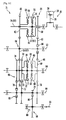
- the transmission 31 is a 4-speed stepped automatic transmission provided with the input shaft 52 and the output shaft 33.
- the transmission 31 is a so-called gear train type stepped transmission, in which power is transmitted to the output shaft 33 from the input shaft 52 through a plurality of change gear pairs.
- crank shaft 34 projects from the crank chamber 35 to reach the transmission chamber 51.
- the crank shaft 34 serves also as the input shaft 52 of the transmission 31.
- the transmission 31 includes the first rotating shaft 53, the second rotating shaft 54, a third rotating shaft 64, and the output shaft 33.
- the first rotating shaft 53, the second rotating shaft 54, the third rotating shaft 64, and the output shaft 33, respectively, are arranged in parallel to the input shaft 52.
- the input shaft 52, the first rotating shaft 53, the second rotating shaft 54, and the third rotating shaft 64 are arranged so that the axis C 1 of the input shaft 52, the axis C2 of the first rotating shaft 53, the axis C3 of the second rotating shaft 54, and the axis C4 of the third rotating shaft 64 constitute a rectangle as viewed in side view.
- the axis C2 of the first rotating shaft 53 is positioned above the plane P
- the axis C4 of the third rotating shaft 64 is positioned below the plane P.
- the axis C2 of the first rotating shaft 53 is positioned on a relatively upper side
- the third rotating shaft 64 is positioned on a relatively lower side. That is, the third rotating shaft 64 is arranged closer to an oil reservoir 99 than the first rotating shaft 53 is.
- the first rotating shaft 53 is arranged in a higher position than that of the oil reservoir 99.
- the third rotating shaft 64 is immersed in the oil reservoir 99.
- the axis C4 of the third rotating shaft 64 is positioned forwardly of the axis C3 of the second rotating shaft 54 in a longitudinal direction. More specifically, the axis C4 of the third rotating shaft 64 is positioned between the axis C3 of the second rotating shaft 54 and the axis C1 of the input shaft 52 in the longitudinal direction.
- the axis C5 of the output shaft 33 is positioned upwardly rearwardly of the axis C4 of the third rotating shaft 64.
- the axis C5 of the output shaft 33 is positioned outside an imaginary rectangle defined by the axis C1 of the input shaft 52, the axis C2 of the first rotating shaft 53, the axis C3 of the second rotating shaft 54, and the axis C4 of the third rotating shaft 64.
- the axis C5 of the output shaft 33 is positioned rearwardly of the axis C3 of the second rotating shaft 54.
- the embodiment will be described with respect to an example, in which the output shaft 33 and the third rotating shaft 64, respectively, are provided separately.
- the invention is not limited to the construction.
- the output shaft 33 and the third rotating shaft 64 may be made common to each other.
- the rear wheel 18 may be mounted to the third rotating shaft 64.
- the third clutch 59 includes an inner 60 as an output side clutch member and an outer 61 as an input side clutch member.
- the inner 60 is provided non-rotatably relative to a ninth gear 62 described later.
- input shaft 52 rotates, its rotation is transmitted to the inner 60 through a first change gear pair 86, the first rotating shaft 53, and a third change gear pair 83. Therefore, the inner 60 rotates together with rotation of the input shaft 52.
- the outer 61 is made rotatable relative to the input shaft 52.
- a centrifugal force acting on the inner 60 brings the inner 60 and the outer 61 into contact with each other. Thereby, the third clutch 59 is connected.
- the outer 57 and the outer 61 are constituted by the same member.
- the invention is not limited to the construction.
- the outer 57 and the outer 61 may comprise a separate member.
- the rotating speed of the input shaft 52 when the first clutch 55 is connected is different from the rotating speed of the input shaft 52 when the third clutch 59 is connected.
- the rotating speed of the inner 56 when the first clutch 55 is connected is different from the rotating speed of the inner 60 when the third clutch 59 is connected.
- the rotating speed of the input shaft 52 when the first clutch 55 is connected is lower than the rotating speed of the input shaft 52 when the third clutch 59 is connected.
- the first clutch 55 is connected when the rotating speed of the input shaft 52 is equal to or more than a first rotating speed.
- the first clutch 55 is put in a disconnected state when the rotating speed of the input shaft 52 is less than the first rotating speed.
- a first gear 58 is provided on the outer 57 of the first clutch 55 to be made non-rotatable relative to the outer 57.
- the first gear 58 rotates together with the outer 57 of the first clutch 55.
- the second gear 63 is provided on the first rotating shaft 53.
- the second gear 63 meshes with the first gear 58.
- the first gear 58 and the second gear 63 constitute a first change gear pair 86.
- the first change gear pair 86 constitutes a 1-speed change gear pair.
- the second gear 63 is a so-called one-way gear. Specifically, the second gear 63 transmits rotation of the first gear 58 to the first rotating shaft 53. On the other hand, the second gear 63 does not transmit rotation of the first rotating shaft 53 to the input shaft 52. That is, the second gear 63 serves as a one-way rotation transmitting mechanism 96.
- the first clutch 55 and the third clutch 59 are positioned between the first change gear pair 86 and the third change gear pair 83. In other words, the first clutch 55 and the third clutch 59 are arranged between the first change gear pair 86 and the third change gear pair 83.
- the sixth gear 78 it is not essential that the sixth gear 78 be a so-called one-way gear.
- the sixth gear 78 may be an ordinary gear and the fifth gear 74 may be a so-called one-way gear.
- the fifth gear 74 may serve as a one-way rotation transmitting mechanism.
- the fifth gear 74 may transmit rotation of the second rotating shaft 54 to the sixth gear 78 but may not transmit rotation of the sixth gear 78 to the second rotating shaft 54.
- the downstream clutch group 82 comprises a second clutch 70 and a fourth clutch 66.
- the fourth clutch 66 is arranged on the right of the second clutch 70. Therefore, a direction, in which the first clutch 55 is positioned relative to the third clutch 59, and a direction, in which the fourth clutch 66 is positioned relative to the second clutch 70, are equal to each other.
- the first clutch 55 and the fourth clutch 66 are arranged to overlap at least partially in the vehicle width direction.
- the first clutch 55 and the fourth clutch 66 are arranged to overlap at least partially in the axial direction of the input shaft 52.
- the third clutch 59 and the second clutch 70 are arranged to overlap at least partially in the vehicle width direction.
- the third clutch 59 and the second clutch 70 are arranged to overlap at least partially in the axial direction of the input shaft 52.
- the first clutch 55 and the fourth clutch 66 are arranged to overlap substantially in the vehicle width direction.
- the third clutch 59 and the second clutch 70 are arranged to overlap substantially in the vehicle width direction.
- one or plural clutches having a relatively large gear ratio, out of the first clutch 55, the third clutch 59, the fourth clutch 66, and the second clutch 70 may comprise a centrifugal clutch and a clutch or clutches having a relatively small gear ratio, other than the clutch or clutches, may comprise a hydraulic clutch.
- the first clutch 55 comprise a centrifugal clutch
- the clutches 59, 66, 70 other than the first clutch may comprise a hydraulic clutch.
- one or plural clutches having a relatively large gear ratio, out of the first clutch 55, the third clutch 59, the fourth clutch 66, and the second clutch 70 may comprise a hydraulic clutch and a clutch or clutches having a relatively small gear ratio, other than the clutch or clutches, may comprise a centrifugal clutch.
- the second clutch 70 comprises the inner 71 as an input side clutch member and an outer 72 as an output side clutch member.
- the inner 71 is provided non-rotatably on the second rotating shaft 54. Therefore, the inner 71 rotates together with rotation of the second rotating shaft 54.
- the outer 72 is rotatable relative to the second rotating shaft 54.
- the seventh gear 73 and the eighth gear 77 constitute a second change gear pair 91.
- the second change gear pair 91 has a different gear ratio from the gear ratio of the first change gear pair 86, the gear ratio of the third change gear pair 83, and the gear ratio of a fourth change gear pair 90.
- the second change gear pair 91 is positioned relative to the second clutch 70 on the same side as that, on which the third change gear pair 83 is positioned relative to the third clutch 59. Specifically, the second change gear pair 91 is positioned on the left of the second clutch 70. Likewise, the third change gear pair 83 is positioned on the left of the third clutch 59.
- downstream clutch group 82 will be described in further detail mainly with reference to Fig. 7 .
- a plate group 136 is provided on the second clutch 70.
- the plate group 136 comprises a plurality of friction plates 134 and a plurality of clutch plates 135.
- the plurality of friction plates 134 and the plurality of clutch plates 135 are alternately laminated in the vehicle width direction.
- the friction plates 134 are non-rotatable relative to the outer 72.
- the clutch plates 135 are non-rotatable relative to the inner 71.
- the inner 71 is rotatable relative to the outer 72.
- a pressure plate 163 is arranged on an opposite side of the inner 71 to the outer 72 in the vehicle width direction.
- the pressure plate 163 is biased rightward in the vehicle width direction by a compression coil spring 92. That is, the pressure plate 163 is biased toward a boss portion 162 by the compression coil spring 92.
- a working chamber 137 is compartmented and formed between the boss portion 162 and the pressure plate 163.
- the working chamber 137 is filled with an oil.
- hydraulic pressure in the working chamber 137 increases, the pressure plate 163 is displaced in a direction away from the boss portion 162. Thereby, a distance between the pressure plate 163 and the inner 71 decreases. Accordingly, the plate group 136 is put in a state of mutual pressure contact. Consequently, the inner 71 and the outer 72 rotate together to put the second clutch 70 in a connected state.
- the inner 67 is rotatable relative to the outer 68 and capable of displacement relative thereto in the vehicle width direction.
- a pressure plate 161 is arranged on an opposite side of the inner 67 to the outer 68 in the vehicle width direction.
- the pressure plate 161 is biased leftward in the vehicle width direction by a compression coil spring 89. That is, the pressure plate 161 is biased toward the boss portion 162 by the compression coil spring 89.
- a working chamber 133 is compartmented and formed between the boss portion 162 and the pressure plate 161.
- the working chamber 133 is filled with an oil.
- hydraulic pressure in the working chamber 133 increases, the pressure plate 161 is displaced in a direction away from the boss portion 162. Thereby, a distance between the pressure plate 161 and the inner 67 decreases. Accordingly, the plate group 132 is put in a state of mutual pressure contact. Consequently, the inner 67 and the outer 68 rotate together to put the fourth clutch 66 in a connected state.
- pressure in the working chamber 133 of the fourth clutch 66 and pressure in the working chamber 137 of the second clutch 70 are given and adjusted by an oil pump 140.
- an oil reservoir 99 is formed on a bottom of the crank chamber 35.
- a strainer 141 is immersed in the oil reservoir 99.
- the strainer 141 is connected to the oil pump 140.
- the oil pump 140 is driven whereby oil accumulated in the oil reservoir 99 is drawn through the strainer 141.
- a relief valve 147 is provided midway through a first oil path 144.
- Oil as drawn is purified by an oil cleaner 142 and regulated to a predetermined pressure by the relief valve 147. Thereafter, a part of the oil as purified is fed to the crank shaft 34 and sliding portions in the cylinder head 40. Also, a part of the oil as purified is also fed to the working chamber 133 of the fourth clutch 66 and the working chamber 137 of the second clutch 70.
- a second oil path 145 and a third oil path 146 are connected to the first oil path 144 extending from the oil cleaner 142.
- the second oil path 145 passes on a side of the transmission cover 50 from a valve 143 and extends into the second rotating shaft 54 from a right end of the second rotating shaft 54.
- the second oil path 145 leads to the working chamber 133. Accordingly, oil is supplied to the working chamber 133 through the second oil path 145 and pressure in the working chamber 133 is regulated.
- the third oil path 146 passes on a side of the crank case 32 from the valve 143 and extends into the second rotating shaft 54 from a left end of the second rotating shaft 54.
- the third oil path 146 leads to the working chamber 137. Accordingly, oil is supplied to the working chamber 137 through the third oil path 146.
- the valve 143 is provided on connections of the first oil path 144 and the second oil path 145 and the third oil path 146.
- the valve 143 provides for opening and closing between the first oil path 144 and the third oil path 146 and opening and closing between the first oil path 144 and the second oil path 145.
- the valve 143 mounts thereto a motor 150, which drives the valve 143.
- the motor 150 drives the valve 143, thereby making the second clutch 70 and the fourth clutch 66 intermittent.
- the oil pump 140, the valve 143, and the motor 150 constitute an actuator 103, which applies hydraulic pressure to the second clutch 70 and the fourth clutch 66, which comprise a hydraulic clutch.
- the actuator 103 is controlled by an ECU 138 shown in Fig. 7 whereby the second clutch 70 and the fourth clutch 66 are regulated in hydraulic pressure.
- the working chamber 133 and the working chamber 137 is regulated in hydraulic pressure.
- the second clutch 70 and the fourth clutch 66 are made intermittent.
- a throttle opening degree sensor 112 and the speed sensor 88 are connected to the ECU 138.
- the ECU 138 as a control unit controls the actuator 103 on the basis of at least one of a throttle opening degree detected by the throttle opening degree sensor 112 and a vehicle speed detected by the speed sensor 88.
- the ECU 138 as a control unit controls the actuator 103 on the basis of both a throttle opening degree detected by the throttle opening degree sensor 112 and a vehicle speed detected by the speed sensor 88.
- the ECU 138 controls the actuator 103 on the basis of information obtained by applying a throttle opening degree output from the throttle opening degree sensor 112 and a vehicle speed output from the speed sensor 88 to a V-N diagram read from a memory 113.
- valve 143 is formed to be substantially columnar-shaped. Formed on the valve 143 are an inner path 148 for opening of the first oil path 144 and the second oil path 145 and an inner path 149 for opening of the first oil path 144 and the third oil path 146.
- the third gear 87 rotates together with the first rotating shaft 53. Therefore, as the first rotating shaft 53 rotates, the first transmission gear pair 84 also rotates. Accordingly, rotation of the first rotating shaft 53 is transmitted to the second rotating shaft 54 through the first transmission gear pair 84.
- the gear ratio of the third change gear pair 83 is smaller than the gear ratio of the first change gear pair 86. Accordingly, the rotating speed of the tenth gear 65 becomes larger than the rotating speed of the second gear 63. Therefore, rotation is transmitted to the first rotating shaft 53 from the input shaft 52 through the third change gear pair 83. On the other hand, rotation of the first rotating shaft 53 is not transmitted to the input shaft 52 by a one-way rotation transmitting mechanism 96.
- Torque is transmitted to the output shaft 33 from the first rotating shaft 53 through the first transmission gear pair 84, the second transmission gear pair 85, and the third transmission gear pair 98 in the same manner as at the time of 1-speed.
- Rotation of the third rotating shaft 64 is transmitted to the output shaft 33 through the third transmission gear pair 98 in the same manner as at the time of 1-speed and at the time of 2-time.
- the embodiment adopts a so-called gear train type transmission 31. Therefore, energy transmission loss is small as compared with, for example, a continuously variable transmission, in which a V-belt is used. Consequently, it is possible to improve a vehicle in fuel consumption.
- the input shaft 52, the first rotating shaft 53, the second rotating shaft 54, the third rotating shaft 64, and the output shaft 33 are arranged in a direction perpendicular to the axial direction of the input shaft 52. That is, the input shaft 52, the first rotating shaft 53, the second rotating shaft 54, the third rotating shaft 64, and the output shaft 33 are arranged to overlap in a direction perpendicular to the axial direction of the input shaft 52.
- the input shaft 52, the first rotating shaft 53, the second rotating shaft 54, the third rotating shaft 64, and the output shaft 33 are arranged to overlap in a direction perpendicular to the axial direction of the input shaft 52. Therefore, it is possible to make the transmission 31 compact in the axial direction of the input shaft 52. Consequently, it is possible to restrict the width of the moped 2 in the vehicle width direction. Accordingly, a bank angle of the moped 2 can be made relatively large.
- the second rotating shaft 54 is preferably arranged so that the axis C3 of the second rotating shaft 54 is positioned to be higher or lower than the axis C1 of the input shaft 52. That is, the input shaft 52 and the second rotating shaft 54 are preferably arranged so that the plane P is inclined to the horizontal. Specifically, the input shaft 52 and the second rotating shaft 54 are preferably arranged so that the plane P becomes rearwardly upward or rearwardly downward. By doing so, a distance between the input shaft 52 and the output shaft 33 can be made further short in a longitudinal direction. Accordingly, it is possible to further lengthen the rear arm 28.
- both the axis C2 of the first rotating shaft 53 and the axis C4 of the third rotating shaft 64 are preferably arranged in other locations than the plane P including the axis C 1 of the input shaft 52 and the axis C3 of the second rotating shaft 54 as in the embodiment.
- the first rotating shaft 53 and the third rotating shaft 64 are especially preferably arranged so that the axis C2 of the first rotating shaft 53 is positioned on one side of the plane P and the axis C4 of the third rotating shaft 64 is positioned on the other side of the plane P.
- the input shaft 52, the first rotating shaft 53, the second rotating shaft 54, and the third rotating shaft 64 adjoin one another.
- a distance between the input shaft 52 and the first rotating shaft 53, a distance between the first rotating shaft 53 and the second rotating shaft 54, and a distance between the second rotating shaft 54 and the third rotating shaft 64, respectively, can be made relatively short. Accordingly, there is no need to separately provide a chain or the like for power transmission between the rotating shafts. Further, there is no need for separate parts such as chain tensioners, chain guides as in case of providing a chain. Therefore, it is possible to make the transmission 31 simple in construction. Also, gears for formation of transmission gear pairs can be made relatively small. Therefore, it is possible to make the transmission 31 light and compact.
- the axis C2 of the first rotating shaft 53 is positioned above the plane P while the axis C4 of the third rotating shaft 64 is positioned below the plane P. Therefore, the first rotating shaft 53, which rotates at a relatively high speed, is arranged in a position relatively distant from the oil reservoir 99 while the third rotating shaft 64, which rotates at a relatively low speed, is arranged in a position relatively close to the oil reservoir 99. In this manner, by arranging the first rotating shaft 53, which rotates at a relatively high speed, in a position distant from the oil reservoir 99, it is possible to inhibit oil in the oil reservoir 99 from being agitated or rippled by rotation of the first rotating shaft 53.
- the first rotating shaft 53 or the third rotating shaft 64 is immersed in the oil reservoir 99, agitation of oil in the oil reservoir 99 can be suppressed and an increase in resistance to rotation of the rotating shaft can be reduced by arranging the third rotating shaft 64, which rotates at a relatively low speed, in the oil reservoir.
- a distance between the input shaft 52 and the second rotating shaft 54 can be made relatively short.
- a rotating shaft arranged in the vicinity of the oil reservoir 99 is preferably as small as possible in rotating speed. This is because resistance to agitation of oil, or the like becomes small.
- the third rotating shaft 64 is a portion, which is reduced in speed relative to the first rotating shaft 53. Therefore, as described above, by positioning the axis C4 of the third rotating shaft 64 below the plane P, it is possible to suppress agitation of oil in the oil reservoir 99 and an increase in resistance to rotation of a rotating shaft (that is, the third rotating shaft 64).
- That technology in which four rotating shafts are provided and a so-called gear train type is adopted, as described in the embodiment is effective for a transmission of 2-speed or more-speed. Further, the technology is effective for a transmission of 3-speed or more-speed, in particular, a transmission of 4-speed or more-speed. The reason for this is that since necessary change gear pairs and clutches are especially many in a transmission of 3-speed, a transmission of 4-speed or more-speed, a whole distance of the engine unit 20 tends to become relatively long.
- the first rotating shaft 53, the second gear 63, or at least a part of the third gear 87 and at least a part of the balancer 115A are arranged so as to overlap each other. Thereby, it is possible to make the transmission 31 slimmer.
- the embodiment has been described with respect to an example, in which the one-way rotation transmitting mechanism 96 is arranged for the second gear 63.
- the invention is not limited to such construction.
- the one-way rotation transmitting mechanism 96 may be arranged for the first gear 58.
- first clutch 55 and the third clutch 59 are arranged between the first change gear pair 86 and the third change gear pair 83.
- the invention is not limited to such construction.
- the first clutch 55 may be arranged on the left of the first change gear pair 86 and the third clutch 59 may also be arranged on the left of the third change gear pair 83.
- the embodiment has been described with respect to an example, in which the second clutch 70 and the fourth clutch 66 are positioned between the second change gear pair 91 and the fourth change gear pair 90.
- the invention is not limited to such construction.
- the second clutch 70 may be arranged on the left of the second change gear pair 91 and the fourth clutch 66 may also be arranged on the left of the fourth change gear pair 90.
- the transmission 31 being relatively small in width can be realized since the input shaft 52, the first rotating shaft 53, the second rotating shaft 54, the third rotating shaft 64, the output shaft 33 are arranged in a longitudinal direction.
- the transmission 31 of 4-speed as an example having a preferred configuration, in which the invention is embodied.
- the invention is not limited to such construction.
- the transmission 31 may be of 5-speed or more-speed.
- the transmission 31 may be one of 3-speed as shown in Fig. 17 .
- a construction, in which the fourth clutch 66 and the second change gear pair 91 of the transmission 31, a construction of which is shown in Fig. 6 , are not provided as shown in Fig. 17 is conceivable.
- the transmission 31 may be one of 2-speed as shown in Fig. 18 .
- a construction, in which the third clutch 59, the fourth change gear pair 90, the one-way rotation transmitting mechanism 96, the fourth clutch 66, and the second change gear pair 91 of the transmission 31, a construction of which is shown in Fig. 6 , are not provided as shown in Fig. 18 is conceivable.
- the engine 30 is a single cylinder engine.
- the engine 30 is not limited to a single cylinder engine.
- the engine 30 may be a multi-cylinder engine such as two cylinder engine.
- the first clutch 55 and the third clutch 59 respectively, comprise a drum type centrifugal clutch.
- the first clutch 55 and the third clutch 59 may comprise a clutch other than a centrifugal clutch.
- the first clutch 55 and the third clutch 59 may comprise a hydraulic clutch.
- the embodiment has been described with respect to an example, in which the first clutch 55 and the third clutch 59, respectively, comprise a disk-type hydraulic clutch.
- the fourth clutch 66 and the second clutch 70 may comprise a clutch other than a hydraulic clutch.
- the fourth clutch 66 and the second clutch 70 may comprise a centrifugal clutch.
- the fourth clutch 66 and the second clutch 70 preferably comprise a hydraulic clutch.
- one or plural clutches having a relatively large gear ratio, out of the first clutch 55, the third clutch 59, the fourth clutch 66, and the second clutch 70 may comprise a centrifugal clutch and a clutch or clutches having a relatively small gear ratio, other than the clutch or clutches, may comprise a hydraulic clutch.
- the first clutch 55 comprise a centrifugal clutch
- the clutches 59, 66, 70 other than the first clutch may comprise a hydraulic clutch.
- the first rotating shaft 53 is arranged so that the axis C2 of the first rotating shaft 53 is positioned to be higher than the axis C4 of the third rotating shaft 64.
- the invention is not limited to the construction.
- the first rotating shaft 53 may be arranged so that the axis C2 of the first rotating shaft 53 is positioned to be lower than the axis C4 of the third rotating shaft 64.
- the first rotating shaft 53 may be arranged so that the axis C2 of the first rotating shaft 53 is positioned below the plane P.
- the third rotating shaft 64 may be arranged so that the axis C4 of the third rotating shaft 64 is positioned above the plane P.
Landscapes
- Engineering & Computer Science (AREA)
- General Engineering & Computer Science (AREA)
- Mechanical Engineering (AREA)
- Structure Of Transmissions (AREA)
- Gear-Shifting Mechanisms (AREA)
- Arrangement Of Transmissions (AREA)
Claims (10)
- Transmission automatique étagée pourvue d'un arbre d'entrée (52) et d'un arbre de sortie (33), comprenant
un premier arbre de rotation (53), un deuxième arbre de rotation (54), et un troisième arbre de rotation (64) connectés à l'arbre de sortie (33), ou constituant l'arbre de sortie (33), chacun de ces arbres étant disposé dans une direction perpendiculaire à une direction axiale de l'arbre d'entrée (52),
un premier embrayage (55) comportant un élément d'embrayage du côté de l'entrée (56) qui tourne ensemble avec l'arbre d'entrée (52), et un élément d'embrayage du côté de la sortie (57) pouvant tourner par rapport à l'arbre d'entrée (52), une première paire d'engrenages de changement de vitesse (86) comportant un premier engrenage (58) qui tourne ensemble avec l'élément d'embrayage du côté de la sortie du premier embrayage (55), et un deuxième engrenage (63) qui engrène le premier engrenage (58) et tourne ensemble avec le premier arbre de rotation (53),
une première paire d'engrenages de transmission (84) comportant un troisième engrenage (87) qui tourne ensemble avec le premier arbre de rotation (53), et un quatrième engrenage (75) qui engrène le troisième engrenage (87) et tourne ensemble avec le deuxième arbre de rotation (54),
une deuxième paire d'engrenages de transmission (85) comportant un cinquième engrenage (74) qui tourne ensemble avec le deuxième arbre de rotation (54), et un sixième engrenage (78) qui engrène le cinquième engrenage (74) et tourne ensemble avec le troisième arbre de rotation (64),
un premier mécanisme de transmission de rotation unidirectionnelle disposé entre le deuxième arbre de rotation (54) et le cinquième engrenage (74), pour transmettre la rotation du deuxième arbre de rotation (54) au cinquième engrenage (74), mais ne pas transmettre la rotation du cinquième engrenage (74) au deuxième arbre de rotation (54), ou un deuxième mécanisme de transmission de rotation unidirectionnelle (93) disposé entre le troisième arbre de rotation (64) et le sixième engrenage (78), pour transmettre la rotation du sixième engrenage (78) au troisième arbre de rotation (64), mais ne pas transmettre la rotation du troisième arbre de rotation (64) au sixième engrenage (78),
un deuxième embrayage (70) comportant un élément d'embrayage du côté de l'entrée (71) qui tourne ensemble avec le deuxième arbre de rotation (54), et un élément d'embrayage du côté de la sortie (72) pouvant tourner par rapport au deuxième arbre de rotation (54), et
une deuxième paire d'engrenages de changement de vitesse (91) comprenant un septième engrenage (73) qui tourne ensemble avec l'élément d'embrayage du côté de la sortie du deuxième embrayage (70), et un huitième engrenage (77) qui engrène le septième engrenage (73) et tourne ensemble avec le troisième arbre de rotation (64), la deuxième paire d'engrenages de changement de vitesse (91) ayant un rapport d'engrenage différent de celui de la première paire d'engrenages de changement de vitesse (86), et
dans laquelle au moins l'un parmi un axe (C2) du premier arbre de rotation (53) et un axe (C4) du troisième arbre de rotation (64) n'est pas présent dans un plan (P) comportant un axe (C1) de l'arbre d'entrée (52) et un axe (C3) du deuxième arbre de rotation (54),
caractérisée par
un troisième embrayage (59) comprenant un élément d'embrayage du côté de l'entrée (56) qui tourne ensemble avec l'arbre d'entrée (52), et un élément d'embrayage du côté de la sortie (57) qui peut tourner par rapport à l'arbre d'entrée (52), et est connecté à la vitesse de rotation de l'arbre d'entrée (52) qui est différente de la vitesse de rotation de l'arbre d'entrée (52) lorsque le premier embrayage (55) est connecté, et
une troisième paire d'engrenages de transmission (83) comportant un neuvième engrenage (62) qui tourne ensemble avec l'élément d'embrayage du côté de la sortie (57) du troisième embrayage (59), et un dixième engrenage (65) qui engrène le neuvième engrenage (62) et tourne ensemble avec le premier arbre de rotation (53), et ayant un rapport d'engrenage différent de ceux de la première paire d'engrenages de transmission (84) et de la deuxième paire d'engrenage de transmission (85). - Transmission automatique étagée selon la revendication 1, dans laquelle l'axe (C2) du premier arbre de rotation (53) est positionné d'un côté du plan et l'axe (C4) du troisième arbre de rotation (64) est positionné de l'autre côté du plan.
- Transmission automatique étagée selon la revendication 2, comprenant par ailleurs un boîtier dans lequel sont logés l'arbre d'entrée (52), l'arbre de sortie (33), le premier arbre de rotation (53), le deuxième arbre de rotation (54), et le troisième arbre de rotation (64), et dont une partie inférieure est formée avec un réservoir d'huile (99), et
dans laquelle l'axe (C2) du premier arbre de rotation (53) est positionné au-dessus du plan (P) et l'axe (C4) du troisième arbre de rotation (64) est positionné au-dessous du plan (P). - Transmission automatique étagée selon la revendication 1, comprenant par ailleurs un quatrième embrayage (66) comportant un élément d'embrayage du côté de l'entrée (61) qui tourne ensemble avec le deuxième arbre de rotation (54), et un élément d'embrayage du côté de la sortie (60) pouvant tourner par rapport au deuxième arbre de rotation (54), le quatrième embrayage (66) étant connecté à une vitesse de rotation différente du deuxième arbre de rotation (54) de celle pour le deuxième embrayage (70), et
une quatrième paire d'engrenages de changement de vitesse (90) comportant un onzième engrenage (69) qui tourne ensemble avec l'élément d'embrayage du côté de la sortie du quatrième d'embrayage (66), et un douzième engrenage (76) qui engrène l'onzième engrenage (69) et tourne ensemble avec le troisième arbre de rotation (64), la quatrième paire d'engrenages de changement de vitesse (90) ayant un rapport d'engrenage différent de ceux de la première paire d'engrenages de changement de vitesse (86), de la deuxième paire d'engrenages de changement de vitesse (91), et de la troisième paire d'engrenages de changement de vitesse (83). - Transmission automatique étagée selon la revendication 1, dans laquelle le troisième arbre de rotation (64) est positionné à l'avant du deuxième arbre de rotation (54) dans une direction longitudinale.
- Unité motrice comprenant une source d'entraînement (30) présentant un vilebrequin (34), et une transmission automatique étagée (31) selon la revendication 1, dans laquelle l'arbre d'entrée (52) est connecté à la source d'entraînement (30).
- Unité motrice selon la revendication 6, dans laquelle la source d'entraînement (30) comprend par ailleurs un balancier comprenant un arbre de balancier (115) connecté au vilebrequin (34), et
le premier arbre de rotation (53), le deuxième engrenage (63), ou au moins une partie du troisième engrenage (87), et au moins une partie du balancier sont disposés de manière à se chevaucher, vu dans la direction axiale du premier arbre de rotation (53). - Motocyclette comprenant l'unité motrice (20) selon la revendication 6.
- Motocyclette selon la revendication 8, dans laquelle un axe (C3) du deuxième arbre de rotation (54) est présent au-dessus ou au-dessous d'un axe (C1) de l'arbre d'entrée (52).
- Motocyclette selon la revendication 8, comprenant par ailleurs un châssis de corps (10), auquel est suspendue l'unité motrice (20) et qui comporte une partie de châssis arrière (10a) positionnée vers l'arrière de l'unité motrice (20),
une roue arrière (18) tournant au fur et à mesure que tourne l'arbre de sortie (33), et
un bras arrière (28) dont une extrémité est montée sur la partie de châssis arrière (10a) de manière à pouvoir osciller, et dont l'autre extrémité est montée de manière rotative sur la roue arrière (18).
Applications Claiming Priority (3)
| Application Number | Priority Date | Filing Date | Title |
|---|---|---|---|
| JP2007214314 | 2007-08-21 | ||
| JP2008204925A JP4327229B2 (ja) | 2007-08-21 | 2008-08-08 | 有段式自動変速装置、それを備えたパワーユニット、及びそれを備えたモーターサイクル |
| PCT/JP2008/064511 WO2009025215A1 (fr) | 2007-08-21 | 2008-08-13 | Dispositif de transmission automatique étagée, unité motrice avec le dispositif de transmission et motocyclette avec l'unité motrice |
Publications (3)
| Publication Number | Publication Date |
|---|---|
| EP2151601A1 EP2151601A1 (fr) | 2010-02-10 |
| EP2151601A4 EP2151601A4 (fr) | 2010-11-03 |
| EP2151601B1 true EP2151601B1 (fr) | 2012-10-17 |
Family
ID=40378121
Family Applications (1)
| Application Number | Title | Priority Date | Filing Date |
|---|---|---|---|
| EP08827990A Not-in-force EP2151601B1 (fr) | 2007-08-21 | 2008-08-13 | Dispositif de transmission automatique étagée, unité motrice avec le dispositif de transmission et motocyclette avec l'unité motrice |
Country Status (11)
| Country | Link |
|---|---|
| EP (1) | EP2151601B1 (fr) |
| JP (1) | JP4327229B2 (fr) |
| CN (1) | CN101779055B (fr) |
| AP (1) | AP2737A (fr) |
| BR (1) | BRPI0814794A2 (fr) |
| CO (1) | CO6261387A2 (fr) |
| ES (1) | ES2397238T3 (fr) |
| MX (1) | MX2010002010A (fr) |
| MY (1) | MY151506A (fr) |
| TW (1) | TWI340214B (fr) |
| WO (1) | WO2009025215A1 (fr) |
Families Citing this family (2)
| Publication number | Priority date | Publication date | Assignee | Title |
|---|---|---|---|---|
| TW201144636A (en) * | 2010-06-11 | 2011-12-16 | meng-hao Ji | Speed-change method and speed-change mechanism for electronic vehicle |
| FR3021594B1 (fr) * | 2014-06-02 | 2017-12-01 | Ifp Energies Now | Dispositif de transmission de vitesse pour le deplacement d'un vehicule automobile, notamment d'un vehicule motorise a deux-roues. |
Family Cites Families (11)
| Publication number | Priority date | Publication date | Assignee | Title |
|---|---|---|---|---|
| BE610636A (fr) | 1960-11-25 | 1962-03-16 | Jean Louis Gratzmuller | Perfectionnements aux changements de vitesse |
| US3219229A (en) * | 1961-09-07 | 1965-11-23 | Ekco Products Company | Sheet metal receptacle |
| JPS5417738Y2 (fr) * | 1973-05-10 | 1979-07-06 | ||
| JPS56142773A (en) * | 1980-04-07 | 1981-11-07 | Yamaha Motor Co Ltd | Power unti for autobicycle, etc. |
| JPS5722448A (en) * | 1980-07-16 | 1982-02-05 | Suzuki Motor Co Ltd | Automatic three-speed gear |
| JPS6028829Y2 (ja) * | 1980-11-18 | 1985-09-02 | ティー・シー・エム株式会社 | 伝導装置 |
| JPS58107927U (ja) * | 1982-01-20 | 1983-07-22 | 本田技研工業株式会社 | 自動二輪車のスイング式パワ−ユニツト |
| JPH0616971Y2 (ja) * | 1986-12-25 | 1994-05-02 | 本田技研工業株式会社 | エンジンのスタ−タ装置 |
| SE467574B (sv) * | 1990-12-10 | 1992-08-10 | Volvo Ab | Stegvaexlad automatvaexellaada foer motorfordon |
| CN2288135Y (zh) * | 1996-04-10 | 1998-08-19 | 李明武 | 无级变速摩托车自动两档变速装置 |
| US6513399B2 (en) * | 2000-12-28 | 2003-02-04 | Case Corp. | Dual power flow counter shaft transmission |
-
2008
- 2008-08-08 JP JP2008204925A patent/JP4327229B2/ja not_active Expired - Fee Related
- 2008-08-13 AP AP2010005125A patent/AP2737A/xx active
- 2008-08-13 WO PCT/JP2008/064511 patent/WO2009025215A1/fr active Application Filing
- 2008-08-13 EP EP08827990A patent/EP2151601B1/fr not_active Not-in-force
- 2008-08-13 ES ES08827990T patent/ES2397238T3/es active Active
- 2008-08-13 MY MYPI20094671 patent/MY151506A/en unknown
- 2008-08-13 CN CN2008800256006A patent/CN101779055B/zh not_active Expired - Fee Related
- 2008-08-13 BR BRPI0814794-9A2A patent/BRPI0814794A2/pt not_active Application Discontinuation
- 2008-08-13 MX MX2010002010A patent/MX2010002010A/es active IP Right Grant
- 2008-08-21 TW TW097131926A patent/TWI340214B/zh not_active IP Right Cessation
-
2010
- 2010-02-02 CO CO10010609A patent/CO6261387A2/es active IP Right Grant
Also Published As
| Publication number | Publication date |
|---|---|
| BRPI0814794A2 (pt) | 2015-02-03 |
| ES2397238T3 (es) | 2013-03-05 |
| EP2151601A1 (fr) | 2010-02-10 |
| EP2151601A4 (fr) | 2010-11-03 |
| AP2010005125A0 (en) | 2010-02-28 |
| CO6261387A2 (es) | 2011-03-22 |
| CN101779055B (zh) | 2013-05-08 |
| TW200928154A (en) | 2009-07-01 |
| JP4327229B2 (ja) | 2009-09-09 |
| WO2009025215A1 (fr) | 2009-02-26 |
| AP2737A (en) | 2013-09-30 |
| MX2010002010A (es) | 2010-03-11 |
| TWI340214B (en) | 2011-04-11 |
| JP2009068698A (ja) | 2009-04-02 |
| CN101779055A (zh) | 2010-07-14 |
| MY151506A (en) | 2014-05-30 |
Similar Documents
| Publication | Publication Date | Title |
|---|---|---|
| AU2014319735B2 (en) | Vehicle power unit | |
| JP2008137417A (ja) | 変速用アクチュエータを備えるエンジン | |
| JP4331785B2 (ja) | パワーユニット及びそれを備えたモーターサイクル | |
| EP2151601B1 (fr) | Dispositif de transmission automatique étagée, unité motrice avec le dispositif de transmission et motocyclette avec l'unité motrice | |
| JP4335960B2 (ja) | 有段式自動変速装置及びそれを備えた車両 | |
| EP2309151B1 (fr) | Transmission automatique séquentielle pour véhicule du type chevauchement de selle, unité de commande équipée de celle-ci, et véhicule du type chevauchement de selle équipé de celle-ci | |
| JP4338764B2 (ja) | 有段式自動変速装置及びそれを備えた車両 | |
| EP2151600B1 (fr) | Dispositif de transmission automatique étagée et motocyclette avec celui-ci | |
| JP5031812B2 (ja) | 変速用アクチュエータを備えるエンジン | |
| JP4319693B2 (ja) | 有段式自動変速装置、それを備えたパワーユニット及び車両 | |
| US8720632B2 (en) | Two-wheeled motor vehicle | |
| JP2009068699A (ja) | 有段式自動変速装置及びそれを備えた車両 | |
| JP4319694B2 (ja) | 鞍乗型車両用の有段式自動変速装置、それを備えたパワーユニット及びそれを備えた鞍乗型車両 | |
| WO2018221410A1 (fr) | Unité de soupape hydraulique, et véhicule de type à selle | |
| JP2011252588A (ja) | 有段式自動変速装置および自動二輪車 |
Legal Events
| Date | Code | Title | Description |
|---|---|---|---|
| PUAI | Public reference made under article 153(3) epc to a published international application that has entered the european phase |
Free format text: ORIGINAL CODE: 0009012 |
|
| 17P | Request for examination filed |
Effective date: 20091207 |
|
| AK | Designated contracting states |
Kind code of ref document: A1 Designated state(s): AT BE BG CH CY CZ DE DK EE ES FI FR GB GR HR HU IE IS IT LI LT LU LV MC MT NL NO PL PT RO SE SI SK TR |
|
| AX | Request for extension of the european patent |
Extension state: AL BA MK RS |
|
| A4 | Supplementary search report drawn up and despatched |
Effective date: 20101005 |
|
| DAX | Request for extension of the european patent (deleted) | ||
| 17Q | First examination report despatched |
Effective date: 20110419 |
|
| REG | Reference to a national code |
Ref country code: DE Ref legal event code: R079 Ref document number: 602008019512 Country of ref document: DE Free format text: PREVIOUS MAIN CLASS: F16H0003083000 Ipc: F16H0003093000 |
|
| RIC1 | Information provided on ipc code assigned before grant |
Ipc: F16H 3/093 20060101AFI20120305BHEP |
|
| GRAP | Despatch of communication of intention to grant a patent |
Free format text: ORIGINAL CODE: EPIDOSNIGR1 |
|
| RIN1 | Information on inventor provided before grant (corrected) |
Inventor name: MURAYAMA, TAKUJI C/O YAMAHA HATSUDOKI KABUSHIKI KA Inventor name: OISHI, AKIFUMIC/O YAMAHA HATSUDOKI KABUSHIKI KAISH |
|
| GRAS | Grant fee paid |
Free format text: ORIGINAL CODE: EPIDOSNIGR3 |
|
| GRAA | (expected) grant |
Free format text: ORIGINAL CODE: 0009210 |
|
| AK | Designated contracting states |
Kind code of ref document: B1 Designated state(s): AT BE BG CH CY CZ DE DK EE ES FI FR GB GR HR HU IE IS IT LI LT LU LV MC MT NL NO PL PT RO SE SI SK TR |
|
| REG | Reference to a national code |
Ref country code: GB Ref legal event code: FG4D |
|
| REG | Reference to a national code |
Ref country code: CH Ref legal event code: EP |
|
| REG | Reference to a national code |
Ref country code: IE Ref legal event code: FG4D |
|
| REG | Reference to a national code |
Ref country code: AT Ref legal event code: REF Ref document number: 580054 Country of ref document: AT Kind code of ref document: T Effective date: 20121115 |
|
| REG | Reference to a national code |
Ref country code: DE Ref legal event code: R096 Ref document number: 602008019512 Country of ref document: DE Effective date: 20121213 |
|
| REG | Reference to a national code |
Ref country code: ES Ref legal event code: FG2A Ref document number: 2397238 Country of ref document: ES Kind code of ref document: T3 Effective date: 20130305 |
|
| REG | Reference to a national code |
Ref country code: AT Ref legal event code: MK05 Ref document number: 580054 Country of ref document: AT Kind code of ref document: T Effective date: 20121017 |
|
| REG | Reference to a national code |
Ref country code: NL Ref legal event code: VDEP Effective date: 20121017 |
|
| REG | Reference to a national code |
Ref country code: LT Ref legal event code: MG4D |
|
| PG25 | Lapsed in a contracting state [announced via postgrant information from national office to epo] |
Ref country code: SE Free format text: LAPSE BECAUSE OF FAILURE TO SUBMIT A TRANSLATION OF THE DESCRIPTION OR TO PAY THE FEE WITHIN THE PRESCRIBED TIME-LIMIT Effective date: 20121017 Ref country code: HR Free format text: LAPSE BECAUSE OF FAILURE TO SUBMIT A TRANSLATION OF THE DESCRIPTION OR TO PAY THE FEE WITHIN THE PRESCRIBED TIME-LIMIT Effective date: 20121017 Ref country code: LT Free format text: LAPSE BECAUSE OF FAILURE TO SUBMIT A TRANSLATION OF THE DESCRIPTION OR TO PAY THE FEE WITHIN THE PRESCRIBED TIME-LIMIT Effective date: 20121017 Ref country code: FI Free format text: LAPSE BECAUSE OF FAILURE TO SUBMIT A TRANSLATION OF THE DESCRIPTION OR TO PAY THE FEE WITHIN THE PRESCRIBED TIME-LIMIT Effective date: 20121017 Ref country code: NO Free format text: LAPSE BECAUSE OF FAILURE TO SUBMIT A TRANSLATION OF THE DESCRIPTION OR TO PAY THE FEE WITHIN THE PRESCRIBED TIME-LIMIT Effective date: 20130117 Ref country code: NL Free format text: LAPSE BECAUSE OF FAILURE TO SUBMIT A TRANSLATION OF THE DESCRIPTION OR TO PAY THE FEE WITHIN THE PRESCRIBED TIME-LIMIT Effective date: 20121017 Ref country code: IS Free format text: LAPSE BECAUSE OF FAILURE TO SUBMIT A TRANSLATION OF THE DESCRIPTION OR TO PAY THE FEE WITHIN THE PRESCRIBED TIME-LIMIT Effective date: 20130217 |
|
| PG25 | Lapsed in a contracting state [announced via postgrant information from national office to epo] |
Ref country code: BE Free format text: LAPSE BECAUSE OF FAILURE TO SUBMIT A TRANSLATION OF THE DESCRIPTION OR TO PAY THE FEE WITHIN THE PRESCRIBED TIME-LIMIT Effective date: 20121017 Ref country code: SI Free format text: LAPSE BECAUSE OF FAILURE TO SUBMIT A TRANSLATION OF THE DESCRIPTION OR TO PAY THE FEE WITHIN THE PRESCRIBED TIME-LIMIT Effective date: 20121017 Ref country code: LV Free format text: LAPSE BECAUSE OF FAILURE TO SUBMIT A TRANSLATION OF THE DESCRIPTION OR TO PAY THE FEE WITHIN THE PRESCRIBED TIME-LIMIT Effective date: 20121017 Ref country code: GR Free format text: LAPSE BECAUSE OF FAILURE TO SUBMIT A TRANSLATION OF THE DESCRIPTION OR TO PAY THE FEE WITHIN THE PRESCRIBED TIME-LIMIT Effective date: 20130118 Ref country code: PT Free format text: LAPSE BECAUSE OF FAILURE TO SUBMIT A TRANSLATION OF THE DESCRIPTION OR TO PAY THE FEE WITHIN THE PRESCRIBED TIME-LIMIT Effective date: 20130218 Ref country code: PL Free format text: LAPSE BECAUSE OF FAILURE TO SUBMIT A TRANSLATION OF THE DESCRIPTION OR TO PAY THE FEE WITHIN THE PRESCRIBED TIME-LIMIT Effective date: 20121017 |
|
| PG25 | Lapsed in a contracting state [announced via postgrant information from national office to epo] |
Ref country code: AT Free format text: LAPSE BECAUSE OF FAILURE TO SUBMIT A TRANSLATION OF THE DESCRIPTION OR TO PAY THE FEE WITHIN THE PRESCRIBED TIME-LIMIT Effective date: 20121017 |
|
| PG25 | Lapsed in a contracting state [announced via postgrant information from national office to epo] |
Ref country code: DK Free format text: LAPSE BECAUSE OF FAILURE TO SUBMIT A TRANSLATION OF THE DESCRIPTION OR TO PAY THE FEE WITHIN THE PRESCRIBED TIME-LIMIT Effective date: 20121017 Ref country code: SK Free format text: LAPSE BECAUSE OF FAILURE TO SUBMIT A TRANSLATION OF THE DESCRIPTION OR TO PAY THE FEE WITHIN THE PRESCRIBED TIME-LIMIT Effective date: 20121017 Ref country code: CZ Free format text: LAPSE BECAUSE OF FAILURE TO SUBMIT A TRANSLATION OF THE DESCRIPTION OR TO PAY THE FEE WITHIN THE PRESCRIBED TIME-LIMIT Effective date: 20121017 Ref country code: EE Free format text: LAPSE BECAUSE OF FAILURE TO SUBMIT A TRANSLATION OF THE DESCRIPTION OR TO PAY THE FEE WITHIN THE PRESCRIBED TIME-LIMIT Effective date: 20121017 Ref country code: BG Free format text: LAPSE BECAUSE OF FAILURE TO SUBMIT A TRANSLATION OF THE DESCRIPTION OR TO PAY THE FEE WITHIN THE PRESCRIBED TIME-LIMIT Effective date: 20130117 |
|
| PLBE | No opposition filed within time limit |
Free format text: ORIGINAL CODE: 0009261 |
|
| STAA | Information on the status of an ep patent application or granted ep patent |
Free format text: STATUS: NO OPPOSITION FILED WITHIN TIME LIMIT |
|
| PG25 | Lapsed in a contracting state [announced via postgrant information from national office to epo] |
Ref country code: RO Free format text: LAPSE BECAUSE OF FAILURE TO SUBMIT A TRANSLATION OF THE DESCRIPTION OR TO PAY THE FEE WITHIN THE PRESCRIBED TIME-LIMIT Effective date: 20121017 |
|
| 26N | No opposition filed |
Effective date: 20130718 |
|
| REG | Reference to a national code |
Ref country code: DE Ref legal event code: R097 Ref document number: 602008019512 Country of ref document: DE Effective date: 20130718 |
|
| PG25 | Lapsed in a contracting state [announced via postgrant information from national office to epo] |
Ref country code: CY Free format text: LAPSE BECAUSE OF FAILURE TO SUBMIT A TRANSLATION OF THE DESCRIPTION OR TO PAY THE FEE WITHIN THE PRESCRIBED TIME-LIMIT Effective date: 20121017 |
|
| REG | Reference to a national code |
Ref country code: CH Ref legal event code: PL |
|
| GBPC | Gb: european patent ceased through non-payment of renewal fee |
Effective date: 20130813 |
|
| PG25 | Lapsed in a contracting state [announced via postgrant information from national office to epo] |
Ref country code: MC Free format text: LAPSE BECAUSE OF FAILURE TO SUBMIT A TRANSLATION OF THE DESCRIPTION OR TO PAY THE FEE WITHIN THE PRESCRIBED TIME-LIMIT Effective date: 20121017 Ref country code: CH Free format text: LAPSE BECAUSE OF NON-PAYMENT OF DUE FEES Effective date: 20130831 Ref country code: LI Free format text: LAPSE BECAUSE OF NON-PAYMENT OF DUE FEES Effective date: 20130831 |
|
| REG | Reference to a national code |
Ref country code: IE Ref legal event code: MM4A |
|
| PG25 | Lapsed in a contracting state [announced via postgrant information from national office to epo] |
Ref country code: IE Free format text: LAPSE BECAUSE OF NON-PAYMENT OF DUE FEES Effective date: 20130813 Ref country code: GB Free format text: LAPSE BECAUSE OF NON-PAYMENT OF DUE FEES Effective date: 20130813 |
|
| PGFP | Annual fee paid to national office [announced via postgrant information from national office to epo] |
Ref country code: DE Payment date: 20140528 Year of fee payment: 7 |
|
| PGFP | Annual fee paid to national office [announced via postgrant information from national office to epo] |
Ref country code: ES Payment date: 20140812 Year of fee payment: 7 Ref country code: FR Payment date: 20140822 Year of fee payment: 7 |
|
| PGFP | Annual fee paid to national office [announced via postgrant information from national office to epo] |
Ref country code: IT Payment date: 20140806 Year of fee payment: 7 |
|
| PG25 | Lapsed in a contracting state [announced via postgrant information from national office to epo] |
Ref country code: MT Free format text: LAPSE BECAUSE OF FAILURE TO SUBMIT A TRANSLATION OF THE DESCRIPTION OR TO PAY THE FEE WITHIN THE PRESCRIBED TIME-LIMIT Effective date: 20121017 Ref country code: TR Free format text: LAPSE BECAUSE OF FAILURE TO SUBMIT A TRANSLATION OF THE DESCRIPTION OR TO PAY THE FEE WITHIN THE PRESCRIBED TIME-LIMIT Effective date: 20121017 |
|
| PG25 | Lapsed in a contracting state [announced via postgrant information from national office to epo] |
Ref country code: LU Free format text: LAPSE BECAUSE OF NON-PAYMENT OF DUE FEES Effective date: 20130813 Ref country code: HU Free format text: LAPSE BECAUSE OF FAILURE TO SUBMIT A TRANSLATION OF THE DESCRIPTION OR TO PAY THE FEE WITHIN THE PRESCRIBED TIME-LIMIT; INVALID AB INITIO Effective date: 20080813 |
|
| REG | Reference to a national code |
Ref country code: DE Ref legal event code: R119 Ref document number: 602008019512 Country of ref document: DE |
|
| PG25 | Lapsed in a contracting state [announced via postgrant information from national office to epo] |
Ref country code: IT Free format text: LAPSE BECAUSE OF NON-PAYMENT OF DUE FEES Effective date: 20150813 |
|
| REG | Reference to a national code |
Ref country code: FR Ref legal event code: ST Effective date: 20160429 |
|
| PG25 | Lapsed in a contracting state [announced via postgrant information from national office to epo] |
Ref country code: DE Free format text: LAPSE BECAUSE OF NON-PAYMENT OF DUE FEES Effective date: 20160301 |
|
| PG25 | Lapsed in a contracting state [announced via postgrant information from national office to epo] |
Ref country code: FR Free format text: LAPSE BECAUSE OF NON-PAYMENT OF DUE FEES Effective date: 20150831 |
|
| REG | Reference to a national code |
Ref country code: ES Ref legal event code: FD2A Effective date: 20160927 |
|
| PG25 | Lapsed in a contracting state [announced via postgrant information from national office to epo] |
Ref country code: ES Free format text: LAPSE BECAUSE OF NON-PAYMENT OF DUE FEES Effective date: 20150814 |