EP2150138B1 - Emptying magazine and transfer mechanism for a hopper emptying apparatus, and hopper emptying apparatus - Google Patents
Emptying magazine and transfer mechanism for a hopper emptying apparatus, and hopper emptying apparatus Download PDFInfo
- Publication number
- EP2150138B1 EP2150138B1 EP08758564.2A EP08758564A EP2150138B1 EP 2150138 B1 EP2150138 B1 EP 2150138B1 EP 08758564 A EP08758564 A EP 08758564A EP 2150138 B1 EP2150138 B1 EP 2150138B1
- Authority
- EP
- European Patent Office
- Prior art keywords
- products
- trays
- discharge hopper
- tray
- emptying
- Prior art date
- Legal status (The legal status is an assumption and is not a legal conclusion. Google has not performed a legal analysis and makes no representation as to the accuracy of the status listed.)
- Not-in-force
Links
Images

Classifications
-
- A—HUMAN NECESSITIES
- A24—TOBACCO; CIGARS; CIGARETTES; SIMULATED SMOKING DEVICES; SMOKERS' REQUISITES
- A24C—MACHINES FOR MAKING CIGARS OR CIGARETTES
- A24C5/00—Making cigarettes; Making tipping materials for, or attaching filters or mouthpieces to, cigars or cigarettes
- A24C5/35—Adaptations of conveying apparatus for transporting cigarettes from making machine to packaging machine
- A24C5/352—Adaptations of conveying apparatus for transporting cigarettes from making machine to packaging machine using containers, i.e. boats
- A24C5/356—Emptying the boats into the hopper of the packaging machine
-
- B—PERFORMING OPERATIONS; TRANSPORTING
- B65—CONVEYING; PACKING; STORING; HANDLING THIN OR FILAMENTARY MATERIAL
- B65B—MACHINES, APPARATUS OR DEVICES FOR, OR METHODS OF, PACKAGING ARTICLES OR MATERIALS; UNPACKING
- B65B19/00—Packaging rod-shaped or tubular articles susceptible to damage by abrasion or pressure, e.g. cigarettes, cigars, macaroni, spaghetti, drinking straws or welding electrodes
- B65B19/02—Packaging cigarettes
- B65B19/04—Arranging, feeding, or orientating the cigarettes
Definitions
- the invention relates to an emptying magazine for a tray emptier for emptying drawer filled with rod-shaped products, comprising a connection means for adapting the drawer to be emptied to the emptying magazine, an at least partially enclosed receiving space for the products flowing out of the tray, wherein the receiving space is in an input area for the product is open at the top and is delimited downwards in a dispensing area for the products, wherein the receiving space in the dispensing area is assigned a sending station which delimits the receiving space for the direct forwarding of the products to downstream devices, so that the sending station is an integral part of the unloading magazine, and wherein a plurality of shaft walls for dividing the receiving space into individual shafts are formed and arranged within the receiving space.
- a tray emptying for emptying filled with rod-shaped products Schragen comprising a feed device for feeding with products filled Schragen, an emptying magazine, arranged above or below the feeder AbtransportINA for transporting emptied Schragen, and a transfer device, by means of the product-filled Schragen of the feeding device in the area of the emptying magazine and the emptied trays are transported from the emptying magazine in the area of Abtransport teeth, part of the invention.
- Such devices or devices are used in particular in the tobacco processing industry. Cigarettes and in particular also filter rods or the like are stored for various reasons in containers, the so-called Schragen.
- the trays are designed as shaft trays in which the products are located in several separate shafts. to Further processing of the products must be reintroduced into the production process or sent to further processing devices or machines.
- tray emptiers usually serve to introduce the products flowing out of the trays into a mass flow.
- the receiving space is downwards, e.g. bounded by a conveyor belt or the like which transports the products from the tray unloader.
- the tray emptiers designed exclusively for emptying the trays have a transfer device, by means of which the trays filled with products can be transported from a feed device into the region of an emptying magazine and the emptied trays from the emptying magazine into the area of a removal device, wherein the transfer device is usually designed as a pivoting device and a closure member which holds the products during the coupling of the trays to the discharge tray in overhead movement in the tray.
- the one-piece closure member is then pivoted away to open the tray or moved to one side so that the products fall out of the tray disorderly and unevenly.
- transmitting stations by means of which products are sent to downstream devices or machines for further processing of the products.
- a device is for example the EP 0 241 789 B1 refer to.
- individual Schragen be placed manually on a pivoting device.
- the pivoting device By means of the pivoting device the trays are emptied overhead in a funnel-shaped magazine of the transmitting device and discharged through arranged at the exit of the magazine transmitting elements or fed to a downstream device.
- the known devices have the drawback that, on the one hand, they require a large amount of space and, in particular, if such devices are combined for emptying and sending, they lead to an unfavorable layout and a complex procedure.
- interfaces are necessarily formed in the combination of the two devices mentioned, which adversely affect process reliability. In other words, every interface in the process increases the risk of errors.
- the known devices have the disadvantage that they tend to so-called transverse flyers.
- the common emptying magazines and transmitting stations are designed in such a way, in particular in the area of the receiving space or the magazine, that the rod-shaped products can cross position during emptying, whereby the entire process comes to a standstill.
- the problem of the mentioned transverse flyers is further enhanced by the fact that known closing elements for the drawer to be emptied is designed such that the products unevenly, so in particular not aligned horizontally, can fall out of the trays.
- An emptying magazine with the features of the preamble of claim 1 is known from DE 41 27 283 A1 known.
- This emptying magazine also has the disadvantages mentioned above. In particular, an orderly transfer and forwarding of the products is problematic.
- an emptying magazine with the features mentioned in the fact that the transmitting station has a plurality of transmitting elements, and each transmitting element for receiving and separating the from the receiving space having flowing rod-shaped products is formed and a connection element for connecting the products forward-conducting pipes, lines or the like.
- the transmitting station By integrating the transmitting station in the emptying magazine, the number of interfaces can be reduced, whereby the reliability is increased.
- the majority and design of the transmitting elements allows the direct and automatic loading of devices for further processing the stored products from the Schragen.
- the emptying of the trays and the forwarding of the products to downstream devices can be performed automatically in a single operation.
- the creation or formation of shafts within the receiving space of the emptying magazine means that the above-described cross-pilots are avoided, since an orderly and uniform emptying of the Schragen is ensured.
- the fact that a shaft wall section of each shaft wall is arranged in the input area of the receiving space, the products are controlled or guided during the transition from Schragen to the emptying magazine.
- the shaft wall portion of each shaft wall in the discharge area ensures that the products are routed safely and evenly to the sending station.
- the combination of the features mentioned ensures that the orderly transfer and forwarding rod-shaped products from Schragen to downstream units is guaranteed safe and reliable.
- each shaft wall is formed within the receiving space of two spaced bay wall sections and a shaft wall portion is in the input area and the other shaft wall portion is arranged in the output area.
- a preferred embodiment is characterized in that each shaft wall section protrudes in the input area of the receiving space in the latter in the direction of the discharge area, such that the drop height of the products is covered by a change of the tray. This means that the shaft wall sections extend into the product reservoir located inside the receiving space. This reliably prevents individual products falling out of the Schrage from becoming transversal flyers.
- a further preferred embodiment is characterized in that each shaft wall section protrudes in the output region of the receiving space in the latter in the direction of the input area, such that the transmission elements of adjacent shafts are completely separated from each other.
- the products are reliably and evenly routed to the individual transmission elements.
- the tray unloader shown in the drawing with the emptying magazine also shown is used for automatic emptying filled with filter rods Schragen and automatic transmission of the filter rods to downstream devices.
- the emptying magazine can also be integrated in other devices or machines.
- other rod-shaped products can be emptied and forwarded.
- the transfer device shown serves to handle the Schragen within the Schragenentleerstation, but can also be used as a single device or in other devices or the like.
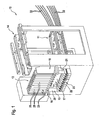
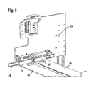
- the tray unloader 10 which essentially comprises a feed device 11 for feeding product-filled trays 12, a discharge magazine 13, a removal device 14 for transporting emptied trays 12 and a transfer device 15 by means of the product-filled trays 12 from the feed device 11 in the Area of the emptying magazine 13 and the emptied trays 12 are transported from the emptying magazine 13 in the area of the removal device 14.
- the feeder 11 and the removal device 14 are arranged one above the other. It does not matter which of the devices 11 and 14 is arranged above or below. In the illustrated embodiment, the feeder 11 is located at the bottom.
- the removal device 14 is arranged directly above and spaced apart by at least one inclined height.
- Both the feed device 11 and the removal device 14 are designed as belt conveyors and extend substantially horizontally.
- the feed device 11 and the removal device 14 may also be designed as chain conveyors or the like and extend depending on the view from the front or from the back into the area of the discharge magazine 13 and are designed and arranged such that a transfer of the tray 12 to the discharge tray 13 by means of Transfer device 15 can be realized.
- the feeding of the full trays 12 and the removal of the empty tray 12 takes place in a substantially horizontal and preferably linear direction.
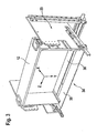
- the emptying magazine 13 which can also be used as a separate unit, serves for emptying the casings 12 filled with products and comprises a connection means 16 for adapting the drawer 12 to be emptied to the emptying hopper 13, an accommodating space 17 at least partially enclosed for the tray 12 flowing products, wherein the receiving space 17 in an input area 18 for the products is open at the top and limited in a discharge area 19 for the products down. At least partially enclosed means that the receiving space 17 does not have to be completely closed.
- the receiving space 17 is defined by two side walls 20, 21 and a rear wall 22 and a boundary described below.
- the receiving space 17 may also have a preferably transparent front wall.
- the opening of the receiving space 17 upward corresponds in cross-section approximately to the cross-sectional opening of the tray 12 is formed in the region of the connecting means 16.
- the connection means 16 may e.g. an adapter frame for at least one tray 12 be.
- Other conventional training for receiving and holding a tray 12 are of course possible.
- the above-mentioned limitation of the receiving space 17 downwards is formed by a transmitting station 23.
- the transmitting station 23 In the output area 19 of the receiving space 17, the transmitting station 23 is arranged for direct forwarding of the products flowing from the receiving space 17 products to downstream devices or machines.
- the emptying magazine 13 with the transmitting station 23 is arranged frontally in front of the feeder 11 or Abtransport nails 14 , so that a supply directly in front of the emptying magazine 13 or a removal is made possible directly from the emptying magazine 13 away.
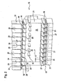
- the receiving space 17 itself is divided in the vertical direction.
- a plurality of shaft walls 24 for dividing the receiving space 17 into individual shafts 25 are formed and arranged within the receiving space 17.
- the shaft walls 24 may be formed continuously. This means that the shaft walls 24 in each case from the input area 18 to the transmitting station 23 in Output area 19 extend.
- each shaft wall 24 is formed from two shaft walls 26, 27 arranged at a distance from one another.
- One of the shaft wall sections 26 is arranged in the input area 18.
- the other shaft wall section is arranged in the region of the output area 19. Between the two aligned well wall sections 26, 27 a distance is provided. In other words, each shaft wall 24 is interrupted in the middle.
- the shaft wall sections 26, 27 of a shaft wall 24 need not be aligned with one another. Rather, the shaft wall sections 26, 27 may be arranged offset to one another.
- the emptying magazine 13 is basically suitable for emptying all embodiments of known trays 12. However, the emptying magazine 13 is particularly preferably designed and set up for emptying shaft trays 12.
- the shaft trays 12 also have a plurality of shafts 29 formed by spaced-apart shaft walls 28.
- the number of shafts 25 within the receiving space 17 of the emptying magazine 13 corresponds to the number of shafts 29 of the tray 12.
- the shaft wall sections 26, 27 of a shaft wall 24, which are preferably aligned with one another, are furthermore preferably aligned or aligned with a corresponding shaft wall 28 of the tray 12 ., So that the shaft wall sections 26 in quasi-input area 18 form an extension of the shaft walls 28. But the shaft walls 24 may be arranged offset to the shaft walls 28.
- each shaft wall 24 is formed in two parts.
- the shaft wall section 26 arranged in the input area 18 projects into the receiving space 17 from top to bottom.
- the length of the shaft wall section 26 may vary, but should be selected at least such that the shaft wall section 26 covers the drop height of the products when the tray 12 is changed.
- the receiving space 17 of the emptying magazine 13 is filled after a first filling with products, wherein the product supply on the one hand continuously discharged from the sending station 23 and on the other hand is continuously refilled from the trays.
- the upper shaft wall sections 26 then reach into the product supply.
- the length of the shaft wall sections 27 in the lower region of the Receiving space 17 is also variable.
- the shaft wall sections 27 protrude from bottom to top into the receiving space 17, whereby individual transmission elements (described further below) of the transmitting station 23 in adjacent shafts 25 are completely separated from one another.
- the shaft wall sections 27 serve quasi las guiding elements to the individual transmitting elements 31st
- Each shaft 25 of the receiving space 17 may optionally be associated with a current regulating means 30.
- Each current regulating means 30 comprises in the described embodiment, for example, an elliptically shaped guide element, which may optionally be mounted or driven stationary or movable. The position of the current regulating means 30 may vary.
- a guide element is preferably arranged between two shaft wall sections 26, 27 of a shaft wall 24.
- each transmitting element 31 is designed to receive and singulate the products flowing out of the receiving space 17.
- each transmitting element 31 comprises a troughed drum, wherein the troughs are adapted to the corresponding shapes of the rod-shaped products.
- Each drum is assigned a scraper element.
- the drums are arranged in or at the bottom of each shaft 25.
- each transmitting element 31 has a connection element (not shown) for connecting pipes 32, lines or the like which forward the products.
- the tubes 32, conduits or the like preferably extend in the same direction as the supply and removal devices 11 and 14, respectively.
- the transfer device 15 within the Schrageentleerers 10 can also be used as a separate unit.
- the transfer device 15 comprises a receptacle 33 for at least one stripping 12.
- the receptacle 33 can be designed and set up for exercising linear movements and / or pivoting movements.
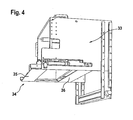
- the receptacle 33 is a pivoting device, by means of which the trays 12 are removed from the feeder 11, pivoted overhead to the emptying magazine 13 and deposited on the Abtransport issued 14. So that the products are held at the overhead pivoting movement in the trays 12, is the transfer device 15 associated with a closing element 34.
- the receptacle 33 is designed for two or more casings 12, correspondingly more closing elements 34 are provided.
- Each closure element 34 is formed in two parts and has two closure elements 35, 36.
- the closure elements 35, 36 are designed to be movable.
- the closure elements 35, 36 are preferably formed as plates movable toward one another and away from one another and the like.
- the oppositely movable closure elements 35, 36 are arranged parallel to the pivot axis of the pivoting device.
- the movement of the closure elements 35, 36 takes place in a common plane holding the products. This plane is preferably oriented horizontally and becomes (see FIG. 3 ) spanned by the X-axis and the Z-axis.
- the movement of the separately drivable closure elements 35, 36 thus takes place in the X direction or counter to the X direction. This direction also corresponds to the orientation of the products within the tray 12.
- the products are also in the X direction in their longitudinal extent.
- the two closure elements 35, 36 are in their (in FIG. 3 shown) closed position preferably spaced from each other. However, the gap or the distance of the two closure elements 35, 36 is in any case less than the length of the products. These are usually with their opposite ends each on a closure element 35 and 36, respectively. From the closed position, the closure elements 35, 36 in the (in FIG. 4 shown) open position brought. For this purpose, the closure elements 35, 36 mounted on movable rotors 37 a linear unit 38 and driven by drive units. The movement of the closure elements 35, 36 can of course be realized in other conventional manner. Within the Schrageentleerers 10, the transfer device 15 may also be formed in a conventional manner.
- the tray emptying device 10 may further be associated with a lifting device (not explicitly shown). This serves in the present embodiment to the fact that the height difference between the feeder 11 and the Abtransport Vietnamese 14 can be compensated.
- the lift device can as be formed separate or independent device.
- the transfer device 15 and the lifting device are formed as an integral unit.
- the transfer device 15 is a pivoting / lifting device.
- the receptacle 33 for example by means of suitable drive means vertically up and down to be movable along guides or the like. Other constructive embodiments of the lift device are also possible.
- emptying magazines 13 is essentially made to the above embodiments, since the structure is basically the same, so that the same reference numerals are used for the same parts.
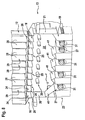
- the embodiment according to FIG. 6 deviates from the in FIG. 2 shown embodiment, that the number of transmitting elements 31 is greater than the number of shafts 25 within the receiving space 17. This can be achieved, for example, that the width in the upper region of the receiving space 17 is less than in the lower region, being used as side walls 20, 21 serving baffles, limiting elements or the like from the top down funnel-shaped.
- the shaft wall sections 26, 27 on the one hand and / or the shaft walls 24 to the shaft walls 28 can also be offset.
- Another embodiment formed according to the principle just described is also the FIG. 7 can be seen, wherein the different number of transmitting elements 31 and shafts 25 by omitting individual shaft walls 24 and shaft wall sections 26 is achieved.
- the embodiment according to FIG. 8 is characterized in that the different number of transmitting elements 31 and shafts 25 is achieved in that are arranged in the region of the transmitting station 23 directly over at least one, but preferably over several transmitting elements 31 covers 41 or the like, so that the underlying transmitting elements 31st are out of order.
- the transmitting elements 31 can also be removed.
- the covers 41 are detachable and thus retrofittable and changeable in particular in the position.
- the number, arrangement and design of the covers 41 may vary.
- the covers 41 are preferably at least partially provided with a downwardly sloping, such that the on the covers 41st falling products in the range of the function of transmitting elements 31 are passed. Other than the training shown are also possible.
- casings 12 filled with rod-shaped products are automatically transported with their broad side in the linear direction by means of the feed device 11 into the region of the emptying magazine 13 or the transfer device 15.
- the transfer device 15 receives an upwardly open tray 12 in the receptacle 33 and pivots it over the top of the discharge tray 13 so that the tray is with the open side down over the connecting means 16 and is adapted to this.
- the closing element 34 holds the products lying on the underlying closure elements 35, 36 in the tray 12.
- another filled tray 12 can be transported by means of the feed device 11 into the region of the discharge magazine 13.
- the closure elements 35, 36 are moved apart in the opposite direction, so that the products over the entire cross section of the opening evenly and in a horizontal orientation down to the receiving space 17.
- the shaft wall sections 26 in the input area 18 ensure that the products are arranged and flow into the receiving space 17 while maintaining their original orientation.
- the receiving space 17 is continuously filled from above. Down the receiving space 17 is continuously emptied by the transmitting elements 31 by the transmitting elements 31 singulate the products and submit via the pipes 32 or the like.
- the closing element 34 is closed and the tray 12 is picked up by means of the transfer device 15 and deposited on the upper removal device 14. This transports the empty tray 12 in a linear direction away from the discharge tray 13.
- the transfer device 15 is selectively moved when picking up the trays from the feeder 11 and / or when delivering the trays to the removal device 14 up and down. While the empty Schragen 12 is removed, the transfer device 15 can receive the next full tray 12 from the feeder 11.
- the emptying and sending of the products is thus carried out in a single fully automated work step, which on the one hand reduces the error rate and on the other hand the costs. Due to the design and arrangement of the Schrageentleerers 10 all process steps are carried out automatically. By horizontally feeding and transporting away the tray 12 in the direction of its broad side, the transfer or otherwise aligning the tray 12 is avoided for emptying. By providing the trays in the position in which they are swiveled over the head in the region of the emptying magazine 13, the travel paths can be shortened and the method as a whole can be carried out in a time- and distance-optimized manner.
Description
Die Erfindung betrifft ein Entleermagazin für einen Schragenentleerer zum Entleeren von mit stabförmigen Produkten gefüllten Schragen, umfassend ein Anschlussmittel zum Adaptieren der zu entleerenden Schragen an das Entleermagazin, einen mindestens teilweise umschlossenen Aufnahmeraum für die aus den Schragen strömenden Produkte, wobei der Aufnahmeraum in einem Eingabebereich für die Produkte nach oben offen und in einem Ausgabebereich für die Produkte nach unten begrenzt ist, wobei dem Aufnahmeraum im Ausgabebereich eine den Aufnahmeraum nach unten begrenzende Sendestation zur direkten Weiterleitung der Produkte an nachgeordnete Vorrichtungen zugeordnet ist, so dass die Sendestation integraler Bestandteil des Entleermagazins ist, und wobei innerhalb des Aufnahmeraums mehrere Schachtwände zur Unterteilung des Aufnahmeraums in einzelne Schächte ausgebildet und angeordnet sind. Weiterhin ist ein Schragenentleerer zum Entleeren von mit stabförmigen Produkten gefüllten Schragen, umfassend eine Zuführeinrichtung zum Zuführen mit Produkten gefüllter Schragen, ein Entleermagazin, eine oberhalb oder unterhalb der Zuführeinrichtung angeordnete Abtransporteinrichtung zum Abtransportieren geleerter Schragen, sowie eine Übergabeeinrichtung, mittels der mit Produkten gefüllte Schragen von der Zuführeinrichtung in den Bereich des Entleermagazins und die entleerten Schragen vom Entleermagazin in den Bereich der Abtransporteinrichtung transportierbar sind, Bestandteil der Erfindung.The invention relates to an emptying magazine for a tray emptier for emptying drawer filled with rod-shaped products, comprising a connection means for adapting the drawer to be emptied to the emptying magazine, an at least partially enclosed receiving space for the products flowing out of the tray, wherein the receiving space is in an input area for the product is open at the top and is delimited downwards in a dispensing area for the products, wherein the receiving space in the dispensing area is assigned a sending station which delimits the receiving space for the direct forwarding of the products to downstream devices, so that the sending station is an integral part of the unloading magazine, and wherein a plurality of shaft walls for dividing the receiving space into individual shafts are formed and arranged within the receiving space. Furthermore, a tray emptying for emptying filled with rod-shaped products Schragen, comprising a feed device for feeding with products filled Schragen, an emptying magazine, arranged above or below the feeder Abtransporteinrichtung for transporting emptied Schragen, and a transfer device, by means of the product-filled Schragen of the feeding device in the area of the emptying magazine and the emptied trays are transported from the emptying magazine in the area of Abtransporteinrichtung, part of the invention.
Solche Einrichtungen bzw. Vorrichtungen kommen insbesondere in der Tabak verarbeitenden Industrie zum Einsatz. Zigaretten und insbesondere auch Filterstäbe oder dergleichen werden aus unterschiedlichen Gründen in Behältern, den so genannten Schragen aufbewahrt. Bevorzugt sind die Schragen als Schachtschragen ausgebildet, in denen die Produkte in mehreren voneinander getrennten Schächten liegen. Zur Weiterverarbeitung der Produkte müssen diese wieder in den Produktionsprozess eingeschleust bzw. an weiter verarbeitende Vorrichtungen bzw. Maschinen gesendet werden.Such devices or devices are used in particular in the tobacco processing industry. Cigarettes and in particular also filter rods or the like are stored for various reasons in containers, the so-called Schragen. Preferably, the trays are designed as shaft trays in which the products are located in several separate shafts. to Further processing of the products must be reintroduced into the production process or sent to further processing devices or machines.
Aus dem Stand der Technik sind unterschiedliche und vor allem separate Vorrichtungen und Maschinen zum Entleeren der Schragen einerseits und zum Senden der Produkte andererseits bekannt. So genannte Schragenentleerer dienen üblicherweise dazu, dass die aus den Schragen strömenden Produkte in einen Massenstrom eingeschleust werden. Hierzu ist der Aufnahmeraum nach unten z.B. durch ein Förderband oder dergleichen begrenzt, das die Produkte aus dem Schragenentleerer transportiert. Die ausschließlich zum Entleeren der Schragen ausgebildeten Schragenentleerer weisen eine Übergabeeinrichtung auf, mittels der die mit Produkten gefüllten Schragen von einer Zuführeinrichtung in den Bereich eines Entleermagazins und die entleerten Schragen vom Entleermagazin in den Bereich einer Abtransporteinrichtung transportierbar sind, wobei die Übergabeeinrichtung üblicherweise als Schwenkeinrichtung ausgebildet ist und ein Schließelement umfasst, das die Produkte während des Koppelns der Schragen an das Entleermagazin bei der über Kopf Bewegung in dem Schragen hält. Das einteilige Schließelement wird dann zum Öffnen der Schragen weggeschwenkt oder zu einer Seite bewegt, so dass die Produkte ungeordnet und ungleichmäßig aus dem Schragen fallen.From the prior art, different and above all separate devices and machines for emptying the Schragen on the one hand and for sending the products on the other hand known. So-called tray emptiers usually serve to introduce the products flowing out of the trays into a mass flow. For this, the receiving space is downwards, e.g. bounded by a conveyor belt or the like which transports the products from the tray unloader. The tray emptiers designed exclusively for emptying the trays have a transfer device, by means of which the trays filled with products can be transported from a feed device into the region of an emptying magazine and the emptied trays from the emptying magazine into the area of a removal device, wherein the transfer device is usually designed as a pivoting device and a closure member which holds the products during the coupling of the trays to the discharge tray in overhead movement in the tray. The one-piece closure member is then pivoted away to open the tray or moved to one side so that the products fall out of the tray disorderly and unevenly.
Aus der
Weiterhin gibt es so genannte Sendestationen, mittels der Produkte an nachgeordnete Vorrichtungen bzw. Maschinen zur Weiterverarbeitung der Produkte gesendet werden. Eine solche Vorrichtung ist z.B. der
Die bekannten Vorrichtungen weisen jedoch den Nachteil auf, dass sie zum einen einen großen Platzbedarf aufweisen, und insbesondere dann, wenn solche Vorrichtungen zum Entleeren und Senden kombiniert werden, zu einem ungünstigen Layout und einem komplexen Verfahren führen. Zum anderen sind bei der Kombination der beiden genannten Vorrichtungen notwendigerweise Schnittstellen gebildet, die die Prozesssicherheit negativ beeinflussen. Anders ausgedrückt steigt mit jeder Schnittstelle im Prozess das Risiko von Fehlern. Weiterhin weisen die bekannten Vorrichtungen den Nachteil auf, dass sie zu so genannten Querfliegern neigen. Mit anderen Worten sind die gängigen Entleermagazine und Sendestationen derart ausgebildet, insbesondere im Bereich des Aufnahmeraumes bzw. des Magazins, dass sich die stabförmigen Produkte beim Entleeren quer stellen können, wodurch der gesamte Prozess zum Stillstand kommt. Die Problematik der erwähnten Querflieger wird noch dadurch verstärkt, dass bekannte Schließelemente für die zu entleerenden Schragen derart ausgebildet ist, dass die Produkte ungleichmäßig, also insbesondere nicht horizontal ausgerichtet, aus den Schragen fallen können.The known devices, however, have the drawback that, on the one hand, they require a large amount of space and, in particular, if such devices are combined for emptying and sending, they lead to an unfavorable layout and a complex procedure. On the other hand, interfaces are necessarily formed in the combination of the two devices mentioned, which adversely affect process reliability. In other words, every interface in the process increases the risk of errors. Furthermore, the known devices have the disadvantage that they tend to so-called transverse flyers. In other words, the common emptying magazines and transmitting stations are designed in such a way, in particular in the area of the receiving space or the magazine, that the rod-shaped products can cross position during emptying, whereby the entire process comes to a standstill. The problem of the mentioned transverse flyers is further enhanced by the fact that known closing elements for the drawer to be emptied is designed such that the products unevenly, so in particular not aligned horizontally, can fall out of the trays.
Ein Entleermagazin mit den Merkmalen des Oberbegriffes des Anspruches 1 ist aus der
Es ist daher Aufgabe der vorliegenden Erfindung, ein kompaktes Entleermagazin bzw. einen kompakten Schragenentleerer zu schaffen, die eine geordnete Übergabe und Weiterleitung stabförmiger Produkte von Schragen an nachgeordnete Einheiten sicher und zuverlässig gewährleisten.It is therefore an object of the present invention to provide a compact discharge magazine or a compact tray emptiers that ensure an orderly transfer and forwarding rod-shaped products of Schragen to downstream units safely and reliably.
Diese Aufgabe wird durch ein Entleermagazin mit den eingangs genannten Merkmalen dadurch gelöst, dass die Sendestation mehrere Sendeelemente aufweist, und jedes Sendeelement zur Aufnahme und Vereinzelung der aus dem Aufnahmeraum strömenden stabförmigen Produkte ausgebildet ist und ein Anschlusselement zum Anschließen von die Produkte weiterleitenden Rohren, Leitungen oder dergleichen aufweist. Dadurch, dass die Sendestation innerhalb des Entleermagazins angeordnet und damit Bestandteil des Entleermagazins ist, kann eine besonders kompakte Einheit zum gleichzeitigen Entleeren und Senden der Produkte bereitgestellt werden. Durch die Integration der Sendestation in das Entleermagazin kann die Anzahl der Schnittstellen reduziert werden, wodurch die Zuverlässigkeit erhöht wird. Die Mehrzahl und Ausbildung der Sendeelemente ermöglicht die direkte und automatische Beschickung von Vorrichtungen zur Weiterverarbeitung der bevorrateten Produkte aus dem Schragen. Anders ausgedrückt kann das Entleeren der Schragen und das Weiterleiten der Produkte an nachgeordnete Vorrichtungen in einem einzigen Arbeitsgang bzw. Prozessschritt automatisch durchgeführt werden. Dadurch, dass sich die Rohre, Leitungen oder dergleichen direkt und unmittelbar an das Entleermagazin anschließen, wird der Entleerungs- und Weiterleitungsprozess vereinfacht und verkürzt.
Die Schaffung bzw. Bildung von Schächten innerhalb des Aufnahmeraumes des Entleermagazins führt dazu, dass die zuvor beschriebenen Querflieger vermieden werden, da eine geordnete und gleichmäßige Entleerung der Schragen sicher gestellt wird. Dadurch, dass ein Schachtwandabschnitt jeder Schachtwand im Eingabebereich des Aufnahmeraums angeordnet ist, werden die Produkte beim Übergang vom Schragen zum Entleermagazin gesteuert bzw. geführt. Der Schachtwandabschnitt jeder Schachtwand im Ausgabebereich stellt sicher, dass die Produkte sicher und gleichmäßig zur Sendestation geleitet werden. Die Kombination der genannten Merkmale stellt sicher, dass die geordnete Übergabe und Weiterleitung stabförmiger Produkte vom Schragen an nachgeordnete Einheiten sicher und zuverlässig gewährleistet ist.This object is achieved by an emptying magazine with the features mentioned in the fact that the transmitting station has a plurality of transmitting elements, and each transmitting element for receiving and separating the from the receiving space having flowing rod-shaped products is formed and a connection element for connecting the products forward-conducting pipes, lines or the like. The fact that the transmitting station is arranged within the emptying magazine and thus is part of the emptying magazine, a particularly compact unit for simultaneous emptying and sending the products can be provided. By integrating the transmitting station in the emptying magazine, the number of interfaces can be reduced, whereby the reliability is increased. The majority and design of the transmitting elements allows the direct and automatic loading of devices for further processing the stored products from the Schragen. In other words, the emptying of the trays and the forwarding of the products to downstream devices can be performed automatically in a single operation. The fact that the pipes, pipes or the like directly and directly connect to the discharge tray, the emptying and forwarding process is simplified and shortened.
The creation or formation of shafts within the receiving space of the emptying magazine means that the above-described cross-pilots are avoided, since an orderly and uniform emptying of the Schragen is ensured. The fact that a shaft wall section of each shaft wall is arranged in the input area of the receiving space, the products are controlled or guided during the transition from Schragen to the emptying magazine. The shaft wall portion of each shaft wall in the discharge area ensures that the products are routed safely and evenly to the sending station. The combination of the features mentioned ensures that the orderly transfer and forwarding rod-shaped products from Schragen to downstream units is guaranteed safe and reliable.
Vorzugsweise ist jede Schachtwand innerhalb des Aufnahmeraums aus zwei beabstandet zueinander angeordneten Schachtwandabschnitten gebildet und ein Schachtwandabschnitt ist im Eingabebereich und der andere Schachtwandabschnitt ist im Ausgabebereich angeordnet. Durch die Unterbrechung der Schachtwand ist ein Ausgleich der Produkte zur Vergleichmäßigung derselben innerhalb des Aufnahmeraums ermöglicht.Preferably, each shaft wall is formed within the receiving space of two spaced bay wall sections and a shaft wall portion is in the input area and the other shaft wall portion is arranged in the output area. By interrupting the shaft wall balancing the products for equalization of the same within the receiving space is possible.
Eine bevorzugte Ausführungsform ist dadurch gekennzeichnet, dass jeder Schachtwandabschnitt im Eingabebereich des Aufnahmeraums in diesen in Richtung des Ausgabebereichs hineinragt, derart, dass die Fallhöhe der Produkte bei einem Wechsel des Schragens überdeckt ist. Das bedeutet, dass die Schachtwandabschnitte in den innerhalb des Aufnahmeraums befindlichen Produktvorrat hineinreichen. Dadurch wird sicher verhindert, dass einzelne aus dem Schragen fallende Produkte zu Querfliegern werden.A preferred embodiment is characterized in that each shaft wall section protrudes in the input area of the receiving space in the latter in the direction of the discharge area, such that the drop height of the products is covered by a change of the tray. This means that the shaft wall sections extend into the product reservoir located inside the receiving space. This reliably prevents individual products falling out of the Schrage from becoming transversal flyers.
Eine weitere bevorzugte Ausführungsform zeichnet sich dadurch aus, dass jeder Schachtwandabschnitt im Ausgabebereich des Aufnahmeraums in diesen in Richtung des Eingabebereichs hineinragt, derart, dass die Sendeelemente benachbarter Schächte vollständig voneinander getrennt sind. Damit werden die Produkte zuverlässig und gleichmäßig zu den einzelnen Sendeelementen geleitet.A further preferred embodiment is characterized in that each shaft wall section protrudes in the output region of the receiving space in the latter in the direction of the input area, such that the transmission elements of adjacent shafts are completely separated from each other. Thus, the products are reliably and evenly routed to the individual transmission elements.
Die Aufgabe wird auch durch einen Schragenentleerer mit den eingangs erwähnten Merkmalen dadurch gelöst, dass das Entleermagazin nach einem der Ansprüche 1 bis 8 ausgebildet ist. Die sich aus der erfindungsgemäßen Ausbildung des Schragenentleerers ergebenden Vorteile wurden bereits im Zusammenhang mit dem Entleermagazin ausführlich erörtert. Zur Vermeidung von Wiederholungen wird auf die entsprechenden Abschnitte verwiesen.The object is also achieved by a tray emptier with the features mentioned in the fact that the emptying magazine is designed according to one of claims 1 to 8. The resulting from the inventive design of Schragenentleerers advantages have already been discussed in detail in connection with the emptying magazine. To avoid repetition, refer to the relevant sections.
Weitere zweckmäßige oder vorteilhafte Merkmale ergeben sich aus den Unteransprüchen und der Beschreibung. Besonders bevorzugte Ausführungsformen sowie das Verfahrensprinzip werden anhand der beigefügten Zeichnung näher erläutert. In der Zeichnung zeigt:
- Fig. 1
- eine perspektivische Darstellung eines Schragenentleerers mit angeschlossenen Rohren/Leitungen zur Weiterleitung der Produkte,
- Fig. 2
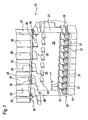
- eine perspektivische Darstellung eines Entleermagazins mit integrierter Sendestation,
- Fig. 3
- eine perspektivische Darstellung einer Übergabeeinrichtung mit geteiltem Schließelement in Schließstellung von schräg oben,
- Fig. 4
- die Übergabeeinrichtung gemäß
Figur 3 mit dem Schließelement in geöffneter Stellung von schräg unten, - Fig. 5
- ein Detail der Übergabeeinrichtung gemäß
Figur 3 , - Fig. 6
- eine weitere Ausführungsform eines Entleermagazins mit integrierter Sendestation,
- Fig. 7
- eine weitere Ausführungsform eines Entleermagazins mit integrierter Sendestation, und
- Fig. 8
- eine weitere Ausführungsform eines Entleermagazins mit integrierter Sendestation.
- Fig. 1
- a perspective view of a Schrägenentleerers with connected pipes / lines for forwarding the products,
- Fig. 2
- a perspective view of an emptying magazine with integrated transmitting station,
- Fig. 3
- a perspective view of a transfer device with shared closing element in the closed position obliquely from above,
- Fig. 4
- the transfer device according to
FIG. 3 with the closing element in the open position obliquely from below, - Fig. 5
- a detail of the transfer device according to
FIG. 3 . - Fig. 6
- a further embodiment of an emptying magazine with integrated transmitting station,
- Fig. 7
- a further embodiment of an emptying magazine with integrated transmitting station, and
- Fig. 8
- Another embodiment of an emptying magazine with integrated transmitting station.
Der in der Zeichnung dargestellte Schragenentleerer mit dem ebenfalls dargestellten Entleermagazin dient zum automatischen Entleeren von mit Filterstäben gefüllten Schragen und automatischen Senden der Filterstäbe an nachgeordnete Vorrichtungen. Selbstverständlich kann das Entleermagazin auch in anderen Vorrichtungen oder Maschinen integriert sein. Auch können andere stabförmige Produkte entleert und weitergeleitet werden. Die gezeigte Übergabeeinrichtung dient zum Handling der Schragen innerhalb der Schragenentleerstation, ist jedoch auch als Einzelvorrichtung oder in anderen Vorrichtungen oder dergleichen einsetzbar.The tray unloader shown in the drawing with the emptying magazine also shown is used for automatic emptying filled with filter rods Schragen and automatic transmission of the filter rods to downstream devices. Of course, the emptying magazine can also be integrated in other devices or machines. Also, other rod-shaped products can be emptied and forwarded. The transfer device shown serves to handle the Schragen within the Schragenentleerstation, but can also be used as a single device or in other devices or the like.
Anhand der
Das Entleermagazin 13, das auch als selbständige Einheit einsetzbar ist, dient zum Entleeren der mit Produkten gefüllten Schragen 12 und umfasst ein Anschlussmittel 16 zum Adaptieren der zu entleerenden Schragen 12 an das Entleermagazin 13, einen mindestens teilweise umschlossenen Aufnahmeraum 17 für die aus dem Schragen 12 strömenden Produkte, wobei der Aufnahmeraum 17 in einem Eingabebereich 18 für die Produkte nach oben offen und in einem Ausgabebereich 19 für die Produkte nach unten begrenzt ist. Mindestens teilweise umschlossen bedeutet, dass der Aufnahmeraum 17 nicht vollständig geschlossen sein muss. In der gezeigten Ausführungsform ist der Aufnahmeraum 17 durch zwei Seitenwände 20, 21 und eine Rückwand 22 sowie eine weiter unten beschriebene Begrenzung definiert. Optional kann der Aufnahmeraum 17 auch eine vorzugsweise transparente Vorderwand aufweisen. Die Öffnung des Aufnahmeraums 17 nach oben entspricht im Querschnitt etwa der Querschnittsöffnung des Schragens 12 ist im Bereich des Anschlussmittels 16 ausgebildet. Das Anschlussmittel 16 kann z.B. ein Adapterrahmen für mindestens einen Schragen 12 sein. Andere übliche Ausbildungen um Aufnehmen und Halten eines Schragens 12 sind selbstverständlich möglich.The emptying
Die oben erwähnte Begrenzung des Aufnahmeraums 17 nach unten wird durch eine Sendestation 23 gebildet. Im Ausgabebereich 19 des Aufnahmeraums 17 ist die Sendestation 23 zur direkten Weiterleitung der aus dem Aufnahmeraum 17 strömenden Produkte an nachgeordnete Vorrichtungen oder Maschinen angeordnet. Dadurch, dass die Sendestation 23 quasi innerhalb des Aufnahmeraums 17 bzw. an dessen Ausgangsbereich 19 angeordnet ist, bildet die Sendestation 23 einen integralen Bestandteil des Entleermagazins 13. Das Entleermagazin 13 mit der Sendestation 23 ist unmittelbar vor der Zuführeinrichtung 11 bzw. Abtransporteinrichtung 14 stirnseitig angeordnet, so dass eine Zuführung unmittelbar vor das Entleermagazin 13 bzw. ein Abtransport unmittelbar vom Entleermagazin 13 weg ermöglicht ist.The above-mentioned limitation of the receiving
Der Aufnahmeraum 17 selbst ist in vertikaler Richtung unterteilt. Vorzugsweise sind innerhalb des Aufnahmeraums 17 mehrere Schachtwände 24 zur Unterteilung des Aufnahmeraums 17 in einzelne Schächte 25 ausgebildet und angeordnet. Die Schachtwände 24 können durchgängig ausgebildet sein. Das bedeutet, dass sich die Schachtwände 24 jeweils vom Eingabebereich 18 bis zur Sendestation 23 im Ausgabebereich 19 erstrecken. Vorzugsweise ist jedoch jede Schachtwand 24 aus zwei beabstandet zueinander angeordneten Schachtwandabschnitten 26, 27 gebildet. Einer der Schachtwandabschnitte 26 ist im Eingabebereich 18 angeordnet. Der andere Schachtwandabschnitt ist im Bereich des Ausgabebereichs 19 angeordnet. Zwischen den beiden fluchtend zueinander ausgerichteten Schachtwandabschnitten 26, 27 ist ein Abstand vorgesehen. Mit anderen Worten ist jede Schachtwand 24 mittig unterbrochen. Alternativ müssen aber die Schachtwandabschnitte 26, 27 einer Schachtwand 24 nicht zueinander fluchtend ausgerichtet sein. Vielmehr können die Schachtwandabschnitte 26, 27 zueinander versetzt angeordnet sein.The receiving
Das Entleermagazin 13 ist grundsätzlich zum Entleeren sämtlicher Ausführungsformen bekannter Schragen 12 geeignet. Besonders bevorzugt ist das Entleermagazin 13 jedoch zum Entleeren von Schachtschragen 12 ausgebildet und eingerichtet. Die Schachtschragen 12 weisen ebenfalls mehrere durch beabstandet zueinander angeordnete Schachtwände 28 gebildete Schächte 29 auf. Die Anzahl der Schächte 25 innerhalb des Aufnahmeraums 17 des Entleermagazins 13 entspricht der Anzahl der Schächte 29 des Schragens 12. Die vorzugsweise zueinander fluchtend angeordneten Schachtwandabschnitte 26, 27 einer Schachtwand 24 sind des Weiteren auch bevorzugt fluchtend zu einer korrespondierenden Schachtwand 28 des Schragens 12 ausgerichtet bzw. angeordnet, so dass die Schachtwandabschnitte 26 im Eingabebereich 18 quasi eine Verlängerung der Schachtwände 28 bilden. Aber auch die Schachtwände 24 können versetzt zu den Schachtwänden 28 angeordnet sein.The emptying
Wie bereits weiter oben beschrieben, ist jede Schachtwand 24 zweiteilig ausgebildet. Der im Eingabebereich 18 angeordnete Schachtwandabschnitt 26 ragt von oben nach unten weisend in den Aufnahmeraum 17 hinein. Die Länge des Schachtwandabschnitts 26 kann variieren, sollte jedoch mindestens so gewählt sein, dass der Schachtwandabschnitt 26 die Fallhöhe der Produkte bei einem Wechsel des Schragens 12 überdeckt. Üblicherweise ist der Aufnahmeraum 17 des Entleermagazins 13 nach einer Erstbefüllung mit Produkten gefüllt, wobei der Produktvorrat einerseits kontinuierlich von der Sendstation 23 abgeführt wird und andererseits kontinuierlich aus den Schragen nachgefüllt wird. Die oberen Schachtwandabschnitte 26 reichen dann bis in den Produktvorrat. Die Länge der Schachtwandabschnitte 27 im unteren Bereich des Aufnahmeraums 17 ist ebenfalls variabel. Die Schachtwandabschnitte 27 ragen von unten nach oben in den Aufnahmeraum 17 hinein, wobei einzelne (weiter unten beschriebenen) Sendeelemente der Sendestation 23 in benachbarten Schächten 25 vollständig voneinander getrennt sind. Die Schachtwandabschnitte 27 dienen quasi las Leitelemente zu den einzelnen Sendeelementen 31.As already described above, each
Jedem Schacht 25 des Aufnahmeraums 17 kann optional ein Stromregulierungsmittel 30 zugeordnet sein. Jedes Stromregulierungsmittel 30 umfasst in der beschriebenen Ausführungsform ein beispielsweise elliptisch geformtes Leitelement, das wahlweise feststehend oder bewegbar gelagert oder angetrieben sein kann. Die Position der Stromregulierungsmittel 30 kann variieren. Bevorzugt ist jeweils ein Leitelement zwischen zwei Schachtwandabschnitten 26, 27 einer Schachtwand 24 angeordnet.Each
Die Sendestation 23 weist wie bereits angedeutet mehrere Sendeelemente 31 auf. Jedes Sendeelement 31 ist zur Aufnahme und Vereinzelung der aus dem Aufnahmeraum 17 strömenden Produkte ausgebildet. Hierzu umfasst jedes Sendeelement 31 eine mit Mulden versehene Trommel, wobei die Mulden an die entsprechenden Formen der stabförmigen Produkte angepasst sind. Jeder Trommel ist ein Abstreiferelement zugeordnet. Die Trommeln sind im bzw. am unteren Bereich jedes Schachtes 25 angeordnet. Des Weiteren verfügt jedes Sendeelement 31 über ein (nicht gezeigtes) Anschlusselement zum Anschließen von die Produkte weiterleitenden Rohre 32, Leitungen oder dergleichen. Die Rohre 32, Leitungen oder dergleichen erstrecken sich vorzugsweise in die gleiche Richtung wie die Zuführ- und Abtransporteinrichtungen 11 bzw. 14.As already indicated, the transmitting
Die Übergabeeinrichtung 15 innerhalb des Schragenentleerers 10 kann auch als selbständige Einheit verwendet werden. Die Übergabeeinrichtung 15 umfasst eine Aufnahme 33 für mindestens einen Schragen 12. Die Aufnahme 33 kann zur Ausübung linearer Bewegungen und/oder Schwenkbewegungen ausgebildet und eingerichtet sein. Vorzugsweise ist die Aufnahme 33 eine Schwenkeinrichtung, mittels der die Schragen 12 von der Zuführeinrichtung 11 abgenommen, über Kopf zum Entleermagazin 13 geschwenkt und auf die Abtransporteinrichtung 14 abgesetzt werden. Damit die Produkte bei der über Kopf Schwenkbewegung in den Schragen 12 gehalten werden, ist der Übergabeeinrichtung 15 ein Schließelement 34 zugeordnet. Für den Fall, dass die Aufnahme 33 für zwei oder mehr Schragen 12 ausgebildet ist, sind entsprechend mehr Schließelemente 34 vorgesehen.The
Jedes Schließelement 34 ist zweiteilig ausgebildet und verfügt über zwei Verschlusselemente 35, 36. Die Verschlusselemente 35, 36 sind bewegbar ausgebildet. Neben der Ausbildung als Schwenkklappen sind die Verschlusselemente 35, 36 vorzugsweise als linear aufeinander zu und voneinander weg bewegliche Platten oder dergleichen ausgebildet. Die entgegengesetzt beweglichen Verschlusselemente 35, 36 sind parallel zur Schwenkachse der Schwenkeinrichtung angeordnet. Die Bewegung der Verschlusselemente 35, 36 erfolgt in einer gemeinsamen die Produkte haltenden Ebene. Diese Ebene ist bevorzugt horizontal ausgerichtet und wird (siehe
Die beiden Verschlusselemente 35, 36 sind in ihrer (in
Dem Schragenentleerer 10 kann des Weiteren eine (nicht explizit dargestellte) Lifteinrichtung zugeordnet sein. Diese dient in der vorliegenden Ausführungsform dazu, dass die Höhendifferenz zwischen der Zuführeinrichtung 11 und der Abtransporteinrichtung 14 ausgeglichen werden kann. Die Lifteinrichtung kann als separate bzw. eigenständige Einrichtung ausgebildet sein. Bevorzugt sind die Übergabeeinrichtung 15 und die Lifteinrichtung als integrale Einheit ausgebildet. Anders ausgedrückt ist die Übergabeeinrichtung 15 eine Schwenk-/Hubeinrichtung. Dabei kann die Aufnahme 33 z.B. mittels geeigneter Antriebsmittel vertikal auf und ab bewegbar entlang von Führungen oder dergleichen sein. Andere konstruktive Ausgestaltungen der Lifteinrichtung sind ebenfalls möglich.The
Bei den in den
Die Ausführungsform gemäß
Im Folgenden wird das Verfahrensprinzip anhand der
Zum Öffnen der Verschlusselemente 35, 36 werden diese in entgegen gesetzter Richtung auseinander gefahren, so das die Produkte über den gesamten Querschnitt der Öffnung gleichmäßig und in horizontaler Ausrichtung nach unten in den Aufnahmeraum 17 gelangen. Dabei stellen die Schachtwandabschnitte 26 im Eingabebereich 18 sicher, dass die Produkte geordnet und unter Beibehaltung ihrer ursprünglichen Ausrichtung in den Aufnahmeraum 17 strömen. Somit wird der Aufnahmeraum 17 von oben kontinuierlich gefüllt. Nach unten wird der Aufnahmeraum 17 kontinuierlich durch die Sendeelemente 31 entleert, indem die Sendeelemente 31 die Produkte vereinzeln und über die Rohre 32 oder dergleichen absenden. Sobald der Schragen 12 vollständig entleert ist, wird das Schließelement 34 geschlossen und der Schragen 12 mittels der Übergabeeinrichtung 15 abgeholt und auf der oberen Abtransporteinrichtung 14 abgesetzt. Diese transportiert die leeren Schragen 12 in linearer Richtung vom Entleermagazin 13 weg. Zur Überwindung der Höhendifferenz zwischen der Zuführeinrichtung 11 und der Abtransporteinrichtung 14 wird die Übergabeeinrichtung 15 wahlweise beim Abholen der Schragen von der Zuführeinrichtung 11 und/oder beim Abgeben der Schragen an die Abtransporteinrichtung 14 nach oben und unten bewegt. Während der leere Schragen 12 abtransportiert wird, kann die Übergabeeinrichtung 15 den nächsten vollen Schragen 12 von der Zuführeinrichtung 11 aufnehmen.To open the
Das Entleeren und Senden der Produkte wird damit in einem einzigen vollautomatischen Arbeitsschritt durchgeführt, was zum einen die Fehlerquote und zum anderen die Kosten senkt. Durch die Ausbildung und Anordnung des Schragenentleerers 10 sind alle Verfahrensschritte automatisch durchzuführen. Durch das horizontale Zuführen und Abtransportieren der Schragen 12 in Richtung ihrer breiten Seite wird das Umsetzen oder anderweitige Ausrichten der Schragen 12 zum Entleeren vermieden. Dadurch, dass die Schragen in der Position, in der sie über Kopf geschwenkt werden, im Bereich des Entleermagazins 13 bereitgestellt werden, können die Verfahrwege verkürzt und das Verfahren insgesamt zeit- und wegoptimiert durchgeführt werden.The emptying and sending of the products is thus carried out in a single fully automated work step, which on the one hand reduces the error rate and on the other hand the costs. Due to the design and arrangement of the
Claims (13)
- A discharge hopper (13) for a tray discharger (10) for emptying trays (12) filled with rod-shaped products, comprising a connecting means (16) for adapting the trays (12) to be emptied to the discharge hopper (13), an at least partially enclosed receiving chamber (17) for the products flowing out of the trays (12), wherein the receiving chamber (17) is open at the top in a input area (18) for the products and is delimited at the bottom in a discharge area (19) for the products, wherein a feed station (23) delimiting the receiving chamber (17) at the bottom is assigned to the receiving chamber (17) in the discharge area (19) for directly forwarding the products to apparatuses arranged downstream, so that the feed station (23) is an integral component of the discharge hopper (13), and wherein a plurality of shaft walls (24) are designed and arranged within the receiving chamber (17) for subdividing the receiving chamber (17) into individual shafts (25), characterised in that the feed station (23) comprises a plurality of feed elements (31) and each feed element (31) is designed to receive and separate the rod-shaped products flowing out of the receiving chamber (17) and has a connecting element for connecting pipes (32), lines or the like forwarding the products.
- Discharge hopper according to claim 1, characterised in that each feed element (31) comprises a drum provided with troughs having at least one scraper element.
- Discharge hopper according to claim 1 or 2, characterised in that the discharge hopper (13) is designed and configured for emptying shaft trays (12).
- Discharge hopper according to claim 3, characterised in that the number of shafts (25) in the receiving chamber (17) corresponds to the number of shafts (29) of a shaft tray (12).
- Discharge hopper according to any one of claims 1 to 4, characterised in that each shaft wall (24) within the receiving chamber (17) is formed from two shaft wall portions (26, 27) arranged spaced apart from one another and one shaft wall portion (26) is arranged in the input area (18) and the other shaft wall portion (27) is arranged in the discharge area (19).
- Discharge hopper according to claim 5, characterised in that the shaft wall portions (26, 27) of a shaft wall (24) within the receiving chamber (17) are aligned with one another and are aligned with a shaft wall (28) of the coupled shaft tray (12).
- Discharge hopper according to claim 5 or 6, characterised in that each shaft wall portion (26) in the input area (18) of the receiving chamber (17) protrudes therein in the direction of the discharge area (19) such that the drop height of the products is covered when changing the tray (12).
- Discharge hopper according to any one of claims 5 to 7, characterised in that each shaft wall portion (27) in the discharge area (19) of the receiving chamber (17) protrudes therein in the direction of the input area (18), such that the feed elements (31) of adjacent shafts (25) are entirely separate from one another.
- A tray discharger (10) for emptying trays (12) filled with rod-shaped products, comprising a feed unit (11) for feeding trays (12) filled with products, a discharge hopper (13), a carry-off device (14) arranged above or below the feed unit (11) for transporting empty trays (12) away as well as a transfer unit (15) by means of which the trays (12) filled with products are able to be transported from the feed unit (11) into the area of the discharge hopper (13) and the empty trays (12) are able to be transported from the discharge hopper (13) into the area of the carry-off device (14), characterised in that the discharge hopper (13) is designed according to any one of claims 1 to 8.
- Tray discharger according to claim 9, characterised in that a lifting device is additionally provided for compensating for the difference in height between the feed unit (11) and the carry-off device (14).
- Tray discharger according to claim 9 or 10, characterised in that the feed unit (11) is arranged below the carry-off device (14).
- Tray discharger according to any one of claims 9 to 11, characterised in that the feed unit (11) and the carry-off device (14) are designed as belt conveyors, chain conveyors or the like for the substantially horizontal conveyance of the trays (12).
- Tray discharger according to any one of claims 9 to 12, characterised in that the transfer unit (15) and the lifting device are designed as an integral unit.
Priority Applications (1)
| Application Number | Priority Date | Filing Date | Title |
|---|---|---|---|
| PL08758564T PL2150138T3 (en) | 2007-05-12 | 2008-05-08 | Emptying magazine and transfer mechanism for a hopper emptying apparatus, and hopper emptying apparatus |
Applications Claiming Priority (2)
| Application Number | Priority Date | Filing Date | Title |
|---|---|---|---|
| DE102007022868A DE102007022868A1 (en) | 2007-05-12 | 2007-05-12 | Emptying magazine and transfer device for a tray emptying, a tray emptying and a method for emptying filled with rod-shaped products Schragen and forwarding the products to downstream devices |
| PCT/EP2008/003930 WO2008138636A2 (en) | 2007-05-12 | 2008-05-08 | Emptying magazine and transfer mechanism for a hopper emptying apparatus, hopper emptying apparatus, and method for emptying hoppers filled with rod-shaped products and forwarding said products to devices located therebehind |
Publications (2)
| Publication Number | Publication Date |
|---|---|
| EP2150138A2 EP2150138A2 (en) | 2010-02-10 |
| EP2150138B1 true EP2150138B1 (en) | 2014-08-20 |
Family
ID=39619390
Family Applications (1)
| Application Number | Title | Priority Date | Filing Date |
|---|---|---|---|
| EP08758564.2A Not-in-force EP2150138B1 (en) | 2007-05-12 | 2008-05-08 | Emptying magazine and transfer mechanism for a hopper emptying apparatus, and hopper emptying apparatus |
Country Status (5)
| Country | Link |
|---|---|
| EP (1) | EP2150138B1 (en) |
| CN (1) | CN101677627B (en) |
| DE (1) | DE102007022868A1 (en) |
| PL (1) | PL2150138T3 (en) |
| WO (1) | WO2008138636A2 (en) |
Families Citing this family (5)
| Publication number | Priority date | Publication date | Assignee | Title |
|---|---|---|---|---|
| PL388251A1 (en) * | 2009-06-10 | 2010-12-20 | International Tobacco Machinery Poland Spółka Z Ograniczoną Odpowiedzialnością | Method for unloading bar-like elements located in a cartridge and a device for unloading cartridges filled with bar-like elements |
| DE102009025568A1 (en) * | 2009-06-13 | 2010-12-16 | Hauni Maschinenbau Ag | Device and method for the successive emptying of containers filled with rod-shaped products |
| PL221043B1 (en) | 2011-08-18 | 2016-02-29 | Int Tobacco Machinery Poland | Filling magazine for multi-segment cartridge filling device |
| DE102013103767A1 (en) * | 2013-04-15 | 2014-10-16 | Hauni Maschinenbau Ag | Slides of conductive plastic and device and method for automatically emptying filled with rod-shaped products Schragen |
| CN106516220A (en) * | 2016-12-06 | 2017-03-22 | 常德瑞华制造有限公司 | Cigarette discharging method and device |
Family Cites Families (11)
| Publication number | Priority date | Publication date | Assignee | Title |
|---|---|---|---|---|
| GB877875A (en) * | 1956-10-18 | 1961-09-20 | James George Edward Hillman | Improvements in or relating to apparatus for collecting cigarettes |
| DE1782884B1 (en) * | 1959-04-02 | 1976-06-24 | Molins Machine Co Ltd | DEVICE FOR PNEUMATIC FEEDING OF FILTER PLUGS |
| DE1915446U (en) * | 1964-03-04 | 1965-05-06 | Hauni Werke Koerber & Co Kg | LOADING DEVICE FOR CIGARETTES OD. DGL. ARTICLE PROCESSING MACHINERY. |
| DE2025657A1 (en) | 1968-11-25 | 1971-12-09 | Hauni Werke Koerber & Co Kg | Arrangement for loading a magazine with rod-shaped articles |
| US3827757A (en) * | 1972-05-05 | 1974-08-06 | Hauni Werke Koerber & Co Kg | Apparatus for transporting rod-shaped articles |
| JPS62230529A (en) | 1986-03-31 | 1987-10-09 | Tokyo Jido Kikai Seisakusho:Kk | Bar feeder in hopper |
| DE3611707A1 (en) * | 1986-04-08 | 1987-10-22 | Hauni Werke Koerber & Co Kg | DEVICE FOR THE PNEUMATIC CONVERSION OF ROD-SHAPED ARTICLES FROM THE TOBACCO-PROCESSING INDUSTRY TO FOLLOW-UP PROCESSING MACHINES |
| DE3612040C2 (en) * | 1986-04-10 | 1995-04-20 | Hauni Werke Koerber & Co Kg | Device for transferring cigarettes from storage containers into a multi-layer article stream |
| DE3708791A1 (en) * | 1987-03-18 | 1988-09-29 | Hauni Werke Koerber & Co Kg | Method and apparatus for filling containers with rod-shaped articles in the tobacco processing industry |
| DE4127283A1 (en) * | 1991-08-03 | 1993-02-04 | Focke & Co | Conveying device for cigarettes in packing machine - has regulated supply and discharge by maintaining horizontal cigarette level in supply chute |
| ITBO20010657A1 (en) * | 2001-10-31 | 2003-05-01 | Gd Spa | METHOD AND SUPPLY EQUIPMENT OF ELONGATED ELEMENTS |
-
2007
- 2007-05-12 DE DE102007022868A patent/DE102007022868A1/en not_active Ceased
-
2008
- 2008-05-08 WO PCT/EP2008/003930 patent/WO2008138636A2/en active Application Filing
- 2008-05-08 PL PL08758564T patent/PL2150138T3/en unknown
- 2008-05-08 CN CN200880015639XA patent/CN101677627B/en not_active Expired - Fee Related
- 2008-05-08 EP EP08758564.2A patent/EP2150138B1/en not_active Not-in-force
Also Published As
| Publication number | Publication date |
|---|---|
| PL2150138T3 (en) | 2015-02-27 |
| CN101677627A (en) | 2010-03-24 |
| WO2008138636A3 (en) | 2009-01-15 |
| DE102007022868A1 (en) | 2008-11-13 |
| WO2008138636A2 (en) | 2008-11-20 |
| EP2150138A2 (en) | 2010-02-10 |
| CN101677627B (en) | 2013-07-10 |
Similar Documents
| Publication | Publication Date | Title |
|---|---|---|
| DE69626731T2 (en) | Granule barrier and granule weighing apparatus with it | |
| EP1952705A2 (en) | Emptying cartridge and method for emptying shaft chamfers filled with rod-shaped products | |
| EP1955604B1 (en) | Method and device for filling containers with rod-shaped objects | |
| EP1952706A1 (en) | Emptying magazine and method for emptying trays filled with rod-shaped objects, in particular shaft trays | |
| EP1900658B1 (en) | Apparatus and method for depositing stacked articles on a conveyor | |
| EP1656841A1 (en) | Device and method for continuously emptying containers filled with articles | |
| EP2150138B1 (en) | Emptying magazine and transfer mechanism for a hopper emptying apparatus, and hopper emptying apparatus | |
| EP2120615B1 (en) | Emptying magazine for a tray emptying device used to empty trays filled with rod-shaped products | |
| EP1743856B1 (en) | Device and method for transporting a stream of articles and device for filling a subsequent device with rod-like articles | |
| EP2220950B1 (en) | Emptying cartridge and method for emptying chamfers filled with rod-shaped objects, in particular shaft chamfers | |
| EP2108271B9 (en) | Emptying cartridge and method for emptying shaft trays filled with rod-shaped products | |
| EP2260732B1 (en) | Device and method for consecutive emptying of containers filled with rod-shaped products | |
| DE2936100A1 (en) | DEVICE FOR LOADING A PACKING MACHINE WITH LONG-STRETCHED ELEMENTS, IN PARTICULAR CIGARETTES | |
| EP2162022B1 (en) | Filling magazine for filling package slots and filling station having such a filling magazine | |
| EP2596708B1 (en) | Handling assembly for transport containers for rod-shaped articles for the tobacco industry and method for changing of the fill level of transport containers | |
| EP2759216A9 (en) | Chute unloading device and method for automatically unloading chutes filled with rod-like articles into a production machine for the tobacco processing industry and a production assembly with a production machine and at least two chute unloading devices | |
| DE10133805A1 (en) | Mechanism for feeding components from store has conveyor, on to which components are fed, gripper removing some components and remainder falling on to third conveyor which recycles them | |
| EP3020287B1 (en) | Arrangement and method for conveying and storing of rod-shaped and/or cuboid products of the processing industry, in particular of the tobacco-processing industry | |
| DE10051790A1 (en) | Cigarette filling system and equipment feeds mass cigarette flow over filling sector whose containers fill with cigarettes at acute angle as container base lowers to maximum fill level | |
| EP2384652A2 (en) | Device for filling chamfers with rod-shaped items and production machine for rod-shaped items with such a device | |
| AT13016U1 (en) | Device and method for selective, unmixed part return | |
| WO1994013161A1 (en) | Storage device | |
| EP3135128A2 (en) | Tray emptying station for emptying trays filled with rod-shaped articles and method for emptying a tray filled with rod-shaped articles by means of a tray emptying station | |
| DE102005034245A1 (en) | Transporting device for e.g. tobacco industry, has trays for accommodating articles transverse to transportation direction, and filling drum and transporting unit that are brought into connection with transferring drum of adjusting device | |
| WO2008138635A1 (en) | Filling magazine for filling package slots and filling station having such a filling magazine |
Legal Events
| Date | Code | Title | Description |
|---|---|---|---|
| PUAI | Public reference made under article 153(3) epc to a published international application that has entered the european phase |
Free format text: ORIGINAL CODE: 0009012 |
|
| 17P | Request for examination filed |
Effective date: 20091208 |
|
| AK | Designated contracting states |
Kind code of ref document: A2 Designated state(s): AT BE BG CH CY CZ DE DK EE ES FI FR GB GR HR HU IE IS IT LI LT LU LV MC MT NL NO PL PT RO SE SI SK TR |
|
| AX | Request for extension of the european patent |
Extension state: AL BA MK RS |
|
| 17Q | First examination report despatched |
Effective date: 20110412 |
|
| DAX | Request for extension of the european patent (deleted) | ||
| GRAP | Despatch of communication of intention to grant a patent |
Free format text: ORIGINAL CODE: EPIDOSNIGR1 |
|
| INTG | Intention to grant announced |
Effective date: 20131004 |
|
| GRAP | Despatch of communication of intention to grant a patent |
Free format text: ORIGINAL CODE: EPIDOSNIGR1 |
|
| INTG | Intention to grant announced |
Effective date: 20140318 |
|
| GRAS | Grant fee paid |
Free format text: ORIGINAL CODE: EPIDOSNIGR3 |
|
| GRAA | (expected) grant |
Free format text: ORIGINAL CODE: 0009210 |
|
| AK | Designated contracting states |
Kind code of ref document: B1 Designated state(s): AT BE BG CH CY CZ DE DK EE ES FI FR GB GR HR HU IE IS IT LI LT LU LV MC MT NL NO PL PT RO SE SI SK TR |
|
| REG | Reference to a national code |
Ref country code: GB Ref legal event code: FG4D Free format text: NOT ENGLISH |
|
| REG | Reference to a national code |
Ref country code: CH Ref legal event code: EP |
|
| REG | Reference to a national code |
Ref country code: AT Ref legal event code: REF Ref document number: 682920 Country of ref document: AT Kind code of ref document: T Effective date: 20140915 |
|
| REG | Reference to a national code |
Ref country code: IE Ref legal event code: FG4D Free format text: LANGUAGE OF EP DOCUMENT: GERMAN |
|
| REG | Reference to a national code |
Ref country code: DE Ref legal event code: R096 Ref document number: 502008012132 Country of ref document: DE Effective date: 20141002 |
|
| REG | Reference to a national code |
Ref country code: NL Ref legal event code: T3 |
|
| REG | Reference to a national code |
Ref country code: LT Ref legal event code: MG4D |
|
| PG25 | Lapsed in a contracting state [announced via postgrant information from national office to epo] |
Ref country code: GR Free format text: LAPSE BECAUSE OF FAILURE TO SUBMIT A TRANSLATION OF THE DESCRIPTION OR TO PAY THE FEE WITHIN THE PRESCRIBED TIME-LIMIT Effective date: 20141121 Ref country code: NO Free format text: LAPSE BECAUSE OF FAILURE TO SUBMIT A TRANSLATION OF THE DESCRIPTION OR TO PAY THE FEE WITHIN THE PRESCRIBED TIME-LIMIT Effective date: 20141120 Ref country code: LT Free format text: LAPSE BECAUSE OF FAILURE TO SUBMIT A TRANSLATION OF THE DESCRIPTION OR TO PAY THE FEE WITHIN THE PRESCRIBED TIME-LIMIT Effective date: 20140820 Ref country code: FI Free format text: LAPSE BECAUSE OF FAILURE TO SUBMIT A TRANSLATION OF THE DESCRIPTION OR TO PAY THE FEE WITHIN THE PRESCRIBED TIME-LIMIT Effective date: 20140820 Ref country code: PT Free format text: LAPSE BECAUSE OF FAILURE TO SUBMIT A TRANSLATION OF THE DESCRIPTION OR TO PAY THE FEE WITHIN THE PRESCRIBED TIME-LIMIT Effective date: 20141222 Ref country code: SE Free format text: LAPSE BECAUSE OF FAILURE TO SUBMIT A TRANSLATION OF THE DESCRIPTION OR TO PAY THE FEE WITHIN THE PRESCRIBED TIME-LIMIT Effective date: 20140820 Ref country code: ES Free format text: LAPSE BECAUSE OF FAILURE TO SUBMIT A TRANSLATION OF THE DESCRIPTION OR TO PAY THE FEE WITHIN THE PRESCRIBED TIME-LIMIT Effective date: 20140820 Ref country code: BG Free format text: LAPSE BECAUSE OF FAILURE TO SUBMIT A TRANSLATION OF THE DESCRIPTION OR TO PAY THE FEE WITHIN THE PRESCRIBED TIME-LIMIT Effective date: 20141120 |
|
| PG25 | Lapsed in a contracting state [announced via postgrant information from national office to epo] |
Ref country code: LV Free format text: LAPSE BECAUSE OF FAILURE TO SUBMIT A TRANSLATION OF THE DESCRIPTION OR TO PAY THE FEE WITHIN THE PRESCRIBED TIME-LIMIT Effective date: 20140820 Ref country code: HR Free format text: LAPSE BECAUSE OF FAILURE TO SUBMIT A TRANSLATION OF THE DESCRIPTION OR TO PAY THE FEE WITHIN THE PRESCRIBED TIME-LIMIT Effective date: 20140820 Ref country code: IS Free format text: LAPSE BECAUSE OF FAILURE TO SUBMIT A TRANSLATION OF THE DESCRIPTION OR TO PAY THE FEE WITHIN THE PRESCRIBED TIME-LIMIT Effective date: 20141220 |
|
| REG | Reference to a national code |
Ref country code: PL Ref legal event code: T3 |
|
| PG25 | Lapsed in a contracting state [announced via postgrant information from national office to epo] |
Ref country code: RO Free format text: LAPSE BECAUSE OF FAILURE TO SUBMIT A TRANSLATION OF THE DESCRIPTION OR TO PAY THE FEE WITHIN THE PRESCRIBED TIME-LIMIT Effective date: 20140820 Ref country code: CZ Free format text: LAPSE BECAUSE OF FAILURE TO SUBMIT A TRANSLATION OF THE DESCRIPTION OR TO PAY THE FEE WITHIN THE PRESCRIBED TIME-LIMIT Effective date: 20140820 Ref country code: DK Free format text: LAPSE BECAUSE OF FAILURE TO SUBMIT A TRANSLATION OF THE DESCRIPTION OR TO PAY THE FEE WITHIN THE PRESCRIBED TIME-LIMIT Effective date: 20140820 Ref country code: EE Free format text: LAPSE BECAUSE OF FAILURE TO SUBMIT A TRANSLATION OF THE DESCRIPTION OR TO PAY THE FEE WITHIN THE PRESCRIBED TIME-LIMIT Effective date: 20140820 Ref country code: SK Free format text: LAPSE BECAUSE OF FAILURE TO SUBMIT A TRANSLATION OF THE DESCRIPTION OR TO PAY THE FEE WITHIN THE PRESCRIBED TIME-LIMIT Effective date: 20140820 |
|
| REG | Reference to a national code |
Ref country code: DE Ref legal event code: R097 Ref document number: 502008012132 Country of ref document: DE |
|
| PLBE | No opposition filed within time limit |
Free format text: ORIGINAL CODE: 0009261 |
|
| STAA | Information on the status of an ep patent application or granted ep patent |
Free format text: STATUS: NO OPPOSITION FILED WITHIN TIME LIMIT |
|
| 26N | No opposition filed |
Effective date: 20150521 |
|
| PG25 | Lapsed in a contracting state [announced via postgrant information from national office to epo] |
Ref country code: SI Free format text: LAPSE BECAUSE OF FAILURE TO SUBMIT A TRANSLATION OF THE DESCRIPTION OR TO PAY THE FEE WITHIN THE PRESCRIBED TIME-LIMIT Effective date: 20140820 |
|
| REG | Reference to a national code |
Ref country code: CH Ref legal event code: PL |
|
| GBPC | Gb: european patent ceased through non-payment of renewal fee |
Effective date: 20150508 |
|
| PG25 | Lapsed in a contracting state [announced via postgrant information from national office to epo] |
Ref country code: LI Free format text: LAPSE BECAUSE OF NON-PAYMENT OF DUE FEES Effective date: 20150531 Ref country code: MC Free format text: LAPSE BECAUSE OF FAILURE TO SUBMIT A TRANSLATION OF THE DESCRIPTION OR TO PAY THE FEE WITHIN THE PRESCRIBED TIME-LIMIT Effective date: 20140820 Ref country code: LU Free format text: LAPSE BECAUSE OF FAILURE TO SUBMIT A TRANSLATION OF THE DESCRIPTION OR TO PAY THE FEE WITHIN THE PRESCRIBED TIME-LIMIT Effective date: 20150508 Ref country code: CH Free format text: LAPSE BECAUSE OF NON-PAYMENT OF DUE FEES Effective date: 20150531 |
|
| REG | Reference to a national code |
Ref country code: IE Ref legal event code: MM4A |
|
| REG | Reference to a national code |
Ref country code: FR Ref legal event code: ST Effective date: 20160129 |
|
| PG25 | Lapsed in a contracting state [announced via postgrant information from national office to epo] |
Ref country code: GB Free format text: LAPSE BECAUSE OF NON-PAYMENT OF DUE FEES Effective date: 20150508 Ref country code: IE Free format text: LAPSE BECAUSE OF NON-PAYMENT OF DUE FEES Effective date: 20150508 |
|
| PG25 | Lapsed in a contracting state [announced via postgrant information from national office to epo] |
Ref country code: FR Free format text: LAPSE BECAUSE OF NON-PAYMENT OF DUE FEES Effective date: 20150601 |
|
| REG | Reference to a national code |
Ref country code: AT Ref legal event code: MM01 Ref document number: 682920 Country of ref document: AT Kind code of ref document: T Effective date: 20150508 |
|
| REG | Reference to a national code |
Ref country code: DE Ref legal event code: R081 Ref document number: 502008012132 Country of ref document: DE Owner name: HAUNI MASCHINENBAU GMBH, DE Free format text: FORMER OWNER: HAUNI MASCHINENBAU AG, 21033 HAMBURG, DE |
|
| PG25 | Lapsed in a contracting state [announced via postgrant information from national office to epo] |
Ref country code: AT Free format text: LAPSE BECAUSE OF NON-PAYMENT OF DUE FEES Effective date: 20150508 |
|
| REG | Reference to a national code |
Ref country code: NL Ref legal event code: PD Owner name: HAUNI MASCHINENBAU GMBH; DE Free format text: DETAILS ASSIGNMENT: VERANDERING VAN EIGENAAR(S), VERANDERING VAN DE JURIDISCHE ENTITEIT; FORMER OWNER NAME: HAUNI MASCHINENBAU AG Effective date: 20160928 |
|
| PG25 | Lapsed in a contracting state [announced via postgrant information from national office to epo] |
Ref country code: MT Free format text: LAPSE BECAUSE OF FAILURE TO SUBMIT A TRANSLATION OF THE DESCRIPTION OR TO PAY THE FEE WITHIN THE PRESCRIBED TIME-LIMIT Effective date: 20140820 |
|
| PG25 | Lapsed in a contracting state [announced via postgrant information from national office to epo] |
Ref country code: HU Free format text: LAPSE BECAUSE OF FAILURE TO SUBMIT A TRANSLATION OF THE DESCRIPTION OR TO PAY THE FEE WITHIN THE PRESCRIBED TIME-LIMIT; INVALID AB INITIO Effective date: 20080508 |
|
| PG25 | Lapsed in a contracting state [announced via postgrant information from national office to epo] |
Ref country code: CY Free format text: LAPSE BECAUSE OF FAILURE TO SUBMIT A TRANSLATION OF THE DESCRIPTION OR TO PAY THE FEE WITHIN THE PRESCRIBED TIME-LIMIT Effective date: 20140820 |
|
| PGFP | Annual fee paid to national office [announced via postgrant information from national office to epo] |
Ref country code: NL Payment date: 20170525 Year of fee payment: 10 |
|
| PG25 | Lapsed in a contracting state [announced via postgrant information from national office to epo] |
Ref country code: BE Free format text: LAPSE BECAUSE OF NON-PAYMENT OF DUE FEES Effective date: 20150531 |
|
| PGFP | Annual fee paid to national office [announced via postgrant information from national office to epo] |
Ref country code: DE Payment date: 20170529 Year of fee payment: 10 |
|
| PG25 | Lapsed in a contracting state [announced via postgrant information from national office to epo] |
Ref country code: TR Free format text: LAPSE BECAUSE OF FAILURE TO SUBMIT A TRANSLATION OF THE DESCRIPTION OR TO PAY THE FEE WITHIN THE PRESCRIBED TIME-LIMIT Effective date: 20140820 |
|
| PGFP | Annual fee paid to national office [announced via postgrant information from national office to epo] |
Ref country code: IT Payment date: 20170531 Year of fee payment: 10 Ref country code: PL Payment date: 20170425 Year of fee payment: 10 |
|
| REG | Reference to a national code |
Ref country code: DE Ref legal event code: R119 Ref document number: 502008012132 Country of ref document: DE |
|
| REG | Reference to a national code |
Ref country code: NL Ref legal event code: MM Effective date: 20180601 |
|
| PG25 | Lapsed in a contracting state [announced via postgrant information from national office to epo] |
Ref country code: IT Free format text: LAPSE BECAUSE OF NON-PAYMENT OF DUE FEES Effective date: 20180508 Ref country code: NL Free format text: LAPSE BECAUSE OF NON-PAYMENT OF DUE FEES Effective date: 20180601 Ref country code: DE Free format text: LAPSE BECAUSE OF NON-PAYMENT OF DUE FEES Effective date: 20181201 |
|
| PG25 | Lapsed in a contracting state [announced via postgrant information from national office to epo] |
Ref country code: PL Free format text: LAPSE BECAUSE OF NON-PAYMENT OF DUE FEES Effective date: 20180508 |