EP2149936B1 - Connector - Google Patents
Connector Download PDFInfo
- Publication number
- EP2149936B1 EP2149936B1 EP08752652.1A EP08752652A EP2149936B1 EP 2149936 B1 EP2149936 B1 EP 2149936B1 EP 08752652 A EP08752652 A EP 08752652A EP 2149936 B1 EP2149936 B1 EP 2149936B1
- Authority
- EP
- European Patent Office
- Prior art keywords
- housing
- engagement locking
- rear holder
- holder
- claw
- Prior art date
- Legal status (The legal status is an assumption and is not a legal conclusion. Google has not performed a legal analysis and makes no representation as to the accuracy of the status listed.)
- Not-in-force
Links
- 210000000078 claw Anatomy 0.000 claims description 41
- 238000000465 moulding Methods 0.000 description 3
- 230000037431 insertion Effects 0.000 description 2
- 238000003780 insertion Methods 0.000 description 2
- 241001071861 Lethrinus genivittatus Species 0.000 description 1
- 239000004020 conductor Substances 0.000 description 1
- 239000000463 material Substances 0.000 description 1
- 239000002184 metal Substances 0.000 description 1
- 238000007789 sealing Methods 0.000 description 1
- 229920003002 synthetic resin Polymers 0.000 description 1
- 239000000057 synthetic resin Substances 0.000 description 1
Images


Classifications
-
- H—ELECTRICITY
- H01—ELECTRIC ELEMENTS
- H01R—ELECTRICALLY-CONDUCTIVE CONNECTIONS; STRUCTURAL ASSOCIATIONS OF A PLURALITY OF MUTUALLY-INSULATED ELECTRICAL CONNECTING ELEMENTS; COUPLING DEVICES; CURRENT COLLECTORS
- H01R13/00—Details of coupling devices of the kinds covered by groups H01R12/70 or H01R24/00 - H01R33/00
- H01R13/40—Securing contact members in or to a base or case; Insulating of contact members
- H01R13/42—Securing in a demountable manner
- H01R13/436—Securing a plurality of contact members by one locking piece or operation
- H01R13/4367—Insertion of locking piece from the rear
- H01R13/4368—Insertion of locking piece from the rear comprising a temporary and a final locking position
-
- H—ELECTRICITY
- H01—ELECTRIC ELEMENTS
- H01R—ELECTRICALLY-CONDUCTIVE CONNECTIONS; STRUCTURAL ASSOCIATIONS OF A PLURALITY OF MUTUALLY-INSULATED ELECTRICAL CONNECTING ELEMENTS; COUPLING DEVICES; CURRENT COLLECTORS
- H01R13/00—Details of coupling devices of the kinds covered by groups H01R12/70 or H01R24/00 - H01R33/00
- H01R13/40—Securing contact members in or to a base or case; Insulating of contact members
- H01R13/42—Securing in a demountable manner
- H01R13/422—Securing in resilient one-piece base or case, e.g. by friction; One-piece base or case formed with resilient locking means
- H01R13/4223—Securing in resilient one-piece base or case, e.g. by friction; One-piece base or case formed with resilient locking means comprising integral flexible contact retaining fingers
- H01R13/4226—Securing in resilient one-piece base or case, e.g. by friction; One-piece base or case formed with resilient locking means comprising integral flexible contact retaining fingers comprising two or more integral flexible retaining fingers acting on a single contact
Definitions
- the present invention relates to a connector including a rear holder for retaining connecting terminals installed within a housing into locked condition.
- a connector has been used in an electric wiring circuit in an automobile.
- a rear holder is detachably provided at a rear portion of a housing, said rear holder being driven into a temporarily engaged position inwhich the rear holder is halfway inserted into the housing as well as into a finally engaged position in which the rear holder is fully inserted into the housing. If the rear holder is fit into the housing after all the necessary connecting terminals have been installed within the housing, it is necessary to pass electric wires having one ends connected to respective connecting terminals through the rear holder. It is apparent that this assembling operation is very cumbersome. Contrary to this, the assembling operation could be performed efficiently by inserting the connecting terminals and electric wires connected to the connecting terminals are inserted into the housing through the rear holder positioned at the temporarily engaged position.
- the locking lances could be formed by molding and the connector could be less expensive, because the locking lances which has to be made of an expensive material having a relatively high durability could be provided in the rear holder having a small size or volume.
- Patent Document 1 Japanese Patent Laid-open Kokai Hei 8-321344
- US5484223 discloses a double terminal stop connector which can prevent a terminal stop frame from being pushed into a connector housing inadvertently.
- DE4328087 discloses a connector of a type in which bolts cannot be fastened until a rear holder is fully inserted into a connecting terminal.
- EP0448476 discloses electrical connectors of a type which has a double lock mechanism for holding electrical terminals in position.
- the rear holders are halfway inserted into the housings up to the temporarily engaged position, and operators of the harness makers insert the connecting terminals into given positions within the housing through the rear holders.
- the present invention has for its object to provide an electrical connector, in which the above mentioned problems can be solved and the rear holder can be stably remained in the temporarily engaged position in which the rear holder is halfway inserted into the housing.
- a connector comprises a housing within which connecting terminals are to be installed, and a rear holder which is inserted into said housing from a rear end of the into a finally engaged position through a temporarily engaged position and includes locking lancers for locking said connecting terminals in position, characterized in that said rear holder includes a temporary engagement locking portion and a final engagement locking portion, said temporary engagement locking portion has a front claw and a rear claw which are separated from each other viewed in an inserting direction of the rear holder, and that said rear holder is locked at the temporarily engaged position by clamping a strip-like temporary engagement locking portion provided on the housing by said front and rear claws.
- the rear holder is locked at the temporarily engaged position by means of the temporary engagement locking portion and could not freely move in the inserting direction with respect to the housing to keep the temporarily engagement state.
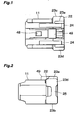
- Figs. 1 and 2 are a plan view and a side view, respectively showing a housing and Figs. 3, 4 and 5 are a plan view, a side view and a front view, respectively illustrating a rear holder.
- the housing 11 is formed to install therein a plurality of connecting terminals and the rear holder 12 is inserted into the housing from a rear portion of the housing and is engaged with the housing such that the connecting terminals installed within the housing are not removed from the housing.
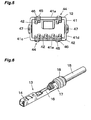
- a connecting terminal 13 shown in Fig. 6 is accommodated within the housing 11.
- the connecting terminal 13 is formed by folding an electrically conductive metal plate.
- a terminal connecting portion 14 of a rectangular cylindrical shape to be connected to a cooperating terminal, a mandrel fixing portion 16 for fixing a core conductor of an electric wire 15 and a sheath fixing portion 17 for fixing an outer sheath of the electric wire 15 are successively provided in the connecting terminal 13 viewed in a front and rear direction.
- a waterproof sealing member 18 At a rear of the sheath fixing portion 17 there may be provided a waterproof sealing member 18.
- the housing 11 and rear holder 12 are formed by molding an electrically insulating synthetic resin.
- the housing 11 is generally formed into a substantially rectangular cylindrical shape, and has formed therein six connecting terminal accommodating rooms 21 for accommodating the connecting terminals 13 independently from one another, two connecting terminal accommodating rooms being formed along an upper row and four connecting terminal accommodating rooms being provided along a lower row. It should be noted that sections and internal structure of the connecting terminal accommodating rooms 21 are not shown in the drawings.
- a rear holder accommodating portion 22 having a size larger than a size of a remaining portion.
- the rear holder 12 has formed therein a rectangular cylindrical shape holder main body 41 which is to be engaged with the rear holder accommodating portion 22 provided at the rear end of the housing 11.
- On a front side of the holder main body 41 there are protruded six locking lances 42 each serving to lock the terminal connecting portion 14 of respective connecting terminals 13 accommodated in the connecting terminal accommodating rooms 21 of the housing 11.
- In a rear wall of the holder main body 41 there are formed five openings, not shown in the figures, through which the connecting terminals 13 having the electric wires 15 connected thereto may be inserted into the housing 11.
- Each of the temporary engagement locking portions 44 includes a pair of front claw 45 and a rear claw 46 which are separated in the rear holder inserting direction. It should be noted that in the present embodiment, the front and rear claws 45 and 46 are also separated in a direction perpendicular to the rear holder inserting direction in relation to the molding. A space between the front and rear claws 45 and 46 in the rear holder inserting direction is set such that the temporary engagement locking ridge 24 of the housing 11 is clamped between the front and rear claws.
- a front side of the front claw 45 is inclined to gradually ascend toward the rear claw 46 and a rear side of the front claw 45 is shaped to form an upright wall.
- a height of the rear claw 46 is smaller than that of the front claw 45 and a front side of the rear claw 46 is formed into an upright wall and a rear side of the rear claw 46 descends toward the rear wall of the rear holder 12. It should be noted that a corner between the front and rear sides of the rear claw46 is somewhat rounded off such that the rear holder can be easily inserted into the final engagedposition without being interrupted by the rear claw 46.
- a final engagement locking claw 47 which is engaged with the final engagement locking ridge 25 of the housing 11.
- a front side of the final engagement locking claw 47 is inclined to gradually ascend toward the rear portion and a rear side of the final engagement locking claw 47 is shaped to form an upright wall.
- the final engagement locking ridge 25 of the housing 11 has an inner surface opposing to the rear holder 12, said inner surface being inclined by an angle identical with an inclined angle of the inclined surface 47a of the final engagement locking claw 47 of the rear holder 12.
- the housing 11 further includes a locking lever provided on a top surface of the housing and a locking claw 48 is provided on the locking lever, said locking claw is to be engaged with a cooperating housing. Upon releasing the locked condition, a push portion 49 formed on the locking lever is pushed downward, and then the locking claw 48 is unlocked from the cooperating housing.
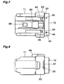
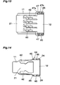
- Figs. 7 and 11 are plan views
- Figs. 8 and 12 are side views
- Figs. 9 and 13 are cross sectional views cut along a horizontal plane
- Figs. 10 and 14 are cross sectional views cut along a vertical plane.
- the temporary engagement locking ridges 24 of the housing 11 are clamped between the front and rear claws 45 and 46 of the temporary engagement locking portions 44 of the rear holder 12 and at the same time, the final engagement locking claws 47 of the rear holder 12 are urged against the final engagement locking ridge 25 of the housing 11. Therefore, the rear holder 12 could not be easily inserted into the housing 11 and the temporarily engaged condition could be remained during the transportation of the connector.
- the connecting terminals 13 having the electric wires 15 connected thereto are inserted into the housing 11 toward respective terminal accommodating rooms 21 of the housing 11 through the openings from in the rear wall of the rear holder 12.
- the terminal connecting portion 14 of the connecting terminal 13 is brought into contact with the locking lance 42 and the locking lance is bent outside.
- the locking lance 42 is bent back toward the original position and is engaged with a rear end of the terminal connecting portion 14. It should be noted that in the temporarily engaged position, the connecting terminals 13 are not fully inserted into the terminal accommodating rooms 21 of the housing 11, but are inserted into temporarily inserted positions.
- the rear holder 12 is further inserted into the housing 11 with a strong force. Then, the rear claws 46 of the temporary engagement locking portion 44 of the rear holder 12 are inserted forwardly beyond the temporary engagement locking ridges 24 of the housing 11 and at the same time, the final engagement locking claws 47 of the rear holder 12 are forcedly moved in the forward direction beyond the final engagement locking ridge 25 of the housing 11. In this manner, the rear holder 12 is completely inserted into the rear holder accommodating portion 22 of the housing 11, and the rear holder 12 is remained in the finally engagedposition shown in Figs. 11-14 by the engagement of the final engagement locking claw 47 with the final engagement locking ridge 25 of the housing 11.
- the connecting terminals 13 are pushed forwardly by the locking lances 42 of the rear holder 12 and are inserted into final positions within the terminal accommodating rooms 21 and are remained therein by means of the locking lances 42.
Landscapes
- Connector Housings Or Holding Contact Members (AREA)
- Details Of Connecting Devices For Male And Female Coupling (AREA)
Applications Claiming Priority (2)
| Application Number | Priority Date | Filing Date | Title |
|---|---|---|---|
| JP2007128873A JP2008287898A (ja) | 2007-05-15 | 2007-05-15 | コネクタ |
| PCT/JP2008/058772 WO2008140082A1 (ja) | 2007-05-15 | 2008-05-13 | コネクタ |
Publications (3)
| Publication Number | Publication Date |
|---|---|
| EP2149936A1 EP2149936A1 (en) | 2010-02-03 |
| EP2149936A4 EP2149936A4 (en) | 2013-08-21 |
| EP2149936B1 true EP2149936B1 (en) | 2014-09-24 |
Family
ID=40002272
Family Applications (1)
| Application Number | Title | Priority Date | Filing Date |
|---|---|---|---|
| EP08752652.1A Not-in-force EP2149936B1 (en) | 2007-05-15 | 2008-05-13 | Connector |
Country Status (6)
| Country | Link |
|---|---|
| US (1) | US8282427B2 (enExample) |
| EP (1) | EP2149936B1 (enExample) |
| JP (1) | JP2008287898A (enExample) |
| KR (1) | KR101459807B1 (enExample) |
| CN (1) | CN101682138B (enExample) |
| WO (1) | WO2008140082A1 (enExample) |
Families Citing this family (10)
| Publication number | Priority date | Publication date | Assignee | Title |
|---|---|---|---|---|
| JP5707252B2 (ja) * | 2011-06-24 | 2015-04-22 | 矢崎総業株式会社 | コネクタ |
| CN108030992A (zh) | 2012-03-15 | 2018-05-15 | 费雪派克医疗保健有限公司 | 呼吸气体加湿系统 |
| DE112013002228T5 (de) | 2012-04-27 | 2015-01-22 | Fisher & Paykel Healthcare Limited | Gebrauchstauglichkeitsfunktionen für ein Atembefeuchtungssystem |
| CA3176652A1 (en) | 2013-09-13 | 2015-03-19 | Fisher And Paykel Healthcare Limited | Circuit connector for a humidification system |
| US10449319B2 (en) | 2014-02-07 | 2019-10-22 | Fisher & Paykel Healthcare Limited | Respiratory humidification system |
| JP6777547B2 (ja) | 2014-06-03 | 2020-10-28 | フィッシャー アンド ペイケル ヘルスケア リミテッド | 呼吸療法システム用の流れ混合器 |
| JP6475669B2 (ja) * | 2016-07-13 | 2019-02-27 | 矢崎総業株式会社 | コネクタ |
| EP3551978B1 (en) | 2016-12-07 | 2022-01-26 | Fisher&Paykel Healthcare Limited | Sensing arrangements for medical devices |
| JP7007724B2 (ja) * | 2018-06-18 | 2022-01-25 | 日本圧着端子製造株式会社 | コネクタ |
| CN110694284B (zh) * | 2019-09-23 | 2021-12-31 | 深圳市优必选科技股份有限公司 | 积木玩具及其连接组件 |
Family Cites Families (14)
| Publication number | Priority date | Publication date | Assignee | Title |
|---|---|---|---|---|
| JPH03106669A (ja) * | 1989-09-20 | 1991-05-07 | Olympus Optical Co Ltd | イオンフロー記録ヘッドアッセンブル |
| JPH03106669U (enExample) * | 1990-02-19 | 1991-11-05 | ||
| US5141452A (en) * | 1990-03-22 | 1992-08-25 | Nissan Motor Co., Ltd. | Electrical connector |
| JPH07114134B2 (ja) * | 1990-10-12 | 1995-12-06 | 矢崎総業株式会社 | 端子係止具付コネクタ |
| JP2651397B2 (ja) * | 1992-04-13 | 1997-09-10 | 矢崎総業株式会社 | 電気コネクタ |
| JP2635486B2 (ja) * | 1992-08-25 | 1997-07-30 | 矢崎総業株式会社 | コネクタ |
| JP2567134Y2 (ja) * | 1993-01-22 | 1998-03-30 | 矢崎総業株式会社 | 二重係止コネクタ |
| JPH06275334A (ja) * | 1993-03-19 | 1994-09-30 | Sumitomo Wiring Syst Ltd | コネクタ |
| JP3534493B2 (ja) * | 1995-05-24 | 2004-06-07 | 菱星電装株式会社 | コネクタ |
| JP4094778B2 (ja) * | 1999-07-27 | 2008-06-04 | 三菱電線工業株式会社 | 電気コネクタ |
| JP4047731B2 (ja) * | 2003-01-10 | 2008-02-13 | 三菱電線工業株式会社 | 電気コネクタ |
| JP4499662B2 (ja) * | 2003-06-18 | 2010-07-07 | 三菱電線工業株式会社 | 電気コネクタ |
| JP3960430B2 (ja) * | 2003-10-16 | 2007-08-15 | タイコエレクトロニクスアンプ株式会社 | 電気コネクタ |
| JP3106669U (ja) | 2004-07-12 | 2005-01-20 | 達隆科技股▲ふん▼有限公司 | ブラシレスファンモータ制御回路 |
-
2007
- 2007-05-15 JP JP2007128873A patent/JP2008287898A/ja active Pending
-
2008
- 2008-05-13 US US12/599,630 patent/US8282427B2/en not_active Expired - Fee Related
- 2008-05-13 KR KR1020097021637A patent/KR101459807B1/ko active Active
- 2008-05-13 WO PCT/JP2008/058772 patent/WO2008140082A1/ja not_active Ceased
- 2008-05-13 CN CN2008800160022A patent/CN101682138B/zh not_active Expired - Fee Related
- 2008-05-13 EP EP08752652.1A patent/EP2149936B1/en not_active Not-in-force
Also Published As
| Publication number | Publication date |
|---|---|
| US20100136853A1 (en) | 2010-06-03 |
| KR20100015644A (ko) | 2010-02-12 |
| WO2008140082A1 (ja) | 2008-11-20 |
| CN101682138B (zh) | 2013-01-02 |
| KR101459807B1 (ko) | 2014-11-07 |
| US8282427B2 (en) | 2012-10-09 |
| EP2149936A4 (en) | 2013-08-21 |
| EP2149936A1 (en) | 2010-02-03 |
| JP2008287898A (ja) | 2008-11-27 |
| CN101682138A (zh) | 2010-03-24 |
Similar Documents
| Publication | Publication Date | Title |
|---|---|---|
| EP2149936B1 (en) | Connector | |
| EP1936749B1 (en) | A terminal fitting, a connector and a forming method | |
| JP3204397B2 (ja) | マイクロピンのコネクタ機構 | |
| EP2101376B1 (en) | Connection member and harness connector | |
| EP2686919B1 (en) | High voltage connector assembly | |
| US7419409B2 (en) | Connection terminal | |
| CN109616829B (zh) | 连接器 | |
| US7074093B2 (en) | Splice absorbing structure for motor vehicle | |
| US20070099520A1 (en) | Connecting terminal | |
| WO2018037904A1 (ja) | ツイストペア線用ジョイントコネクタ | |
| EP1104048A2 (en) | Blind mate electrical connector with mechanical assist means | |
| EP0963009B1 (en) | A construction for preventing an error assembling of a connector housing and a cover and a connector comprising the same | |
| US8021199B2 (en) | Electrical connector having large locking force | |
| US7008254B2 (en) | Connector | |
| EP1548894B1 (en) | A connector | |
| US20060199423A1 (en) | Press-contact connector | |
| EP0393879A2 (en) | Electrical connector system and insulation displacement terminals therefor | |
| EP1134848B1 (en) | A connector and a set of terminal fittings | |
| US7214090B2 (en) | Connector device | |
| JP2008198392A (ja) | ジョイントコネクタ | |
| JP5107004B2 (ja) | 合体コネクタ | |
| EP1746689B1 (en) | A divided connector and a method of assembling it | |
| EP4471995A1 (en) | Integrated terminal position assurance and corresponding electrical connector | |
| EP1577982B1 (en) | Electrical junction box and continuity inspection jig assembly fitted on the electrical junction box | |
| JP3275281B2 (ja) | ジョイントコネクタ |
Legal Events
| Date | Code | Title | Description |
|---|---|---|---|
| PUAI | Public reference made under article 153(3) epc to a published international application that has entered the european phase |
Free format text: ORIGINAL CODE: 0009012 |
|
| 17P | Request for examination filed |
Effective date: 20091214 |
|
| AK | Designated contracting states |
Kind code of ref document: A1 Designated state(s): AT BE BG CH CY CZ DE DK EE ES FI FR GB GR HR HU IE IS IT LI LT LU LV MC MT NL NO PL PT RO SE SI SK TR |
|
| AX | Request for extension of the european patent |
Extension state: AL BA MK RS |
|
| RIN1 | Information on inventor provided before grant (corrected) |
Inventor name: YAMAZAKI, TOMOHIRO |
|
| DAX | Request for extension of the european patent (deleted) | ||
| RAP1 | Party data changed (applicant data changed or rights of an application transferred) |
Owner name: FURUKAWA AUTOMOTIVE SYSTEMS INC. Owner name: FURUKAWA ELECTRIC CO., LTD. |
|
| A4 | Supplementary search report drawn up and despatched |
Effective date: 20130722 |
|
| RIC1 | Information provided on ipc code assigned before grant |
Ipc: H01R 13/422 20060101ALI20130716BHEP Ipc: H01R 13/436 20060101ALI20130716BHEP Ipc: H01R 13/42 20060101AFI20130716BHEP |
|
| GRAP | Despatch of communication of intention to grant a patent |
Free format text: ORIGINAL CODE: EPIDOSNIGR1 |
|
| INTG | Intention to grant announced |
Effective date: 20140416 |
|
| RIN1 | Information on inventor provided before grant (corrected) |
Inventor name: YAMAZAKI, TOMOHIRO |
|
| GRAS | Grant fee paid |
Free format text: ORIGINAL CODE: EPIDOSNIGR3 |
|
| GRAA | (expected) grant |
Free format text: ORIGINAL CODE: 0009210 |
|
| AK | Designated contracting states |
Kind code of ref document: B1 Designated state(s): AT BE BG CH CY CZ DE DK EE ES FI FR GB GR HR HU IE IS IT LI LT LU LV MC MT NL NO PL PT RO SE SI SK TR |
|
| REG | Reference to a national code |
Ref country code: GB Ref legal event code: FG4D |
|
| REG | Reference to a national code |
Ref country code: CH Ref legal event code: EP |
|
| REG | Reference to a national code |
Ref country code: AT Ref legal event code: REF Ref document number: 688969 Country of ref document: AT Kind code of ref document: T Effective date: 20141015 |
|
| REG | Reference to a national code |
Ref country code: IE Ref legal event code: FG4D |
|
| REG | Reference to a national code |
Ref country code: DE Ref legal event code: R096 Ref document number: 602008034561 Country of ref document: DE Effective date: 20141106 |
|
| PG25 | Lapsed in a contracting state [announced via postgrant information from national office to epo] |
Ref country code: GR Free format text: LAPSE BECAUSE OF FAILURE TO SUBMIT A TRANSLATION OF THE DESCRIPTION OR TO PAY THE FEE WITHIN THE PRESCRIBED TIME-LIMIT Effective date: 20141225 Ref country code: SE Free format text: LAPSE BECAUSE OF FAILURE TO SUBMIT A TRANSLATION OF THE DESCRIPTION OR TO PAY THE FEE WITHIN THE PRESCRIBED TIME-LIMIT Effective date: 20140924 Ref country code: NO Free format text: LAPSE BECAUSE OF FAILURE TO SUBMIT A TRANSLATION OF THE DESCRIPTION OR TO PAY THE FEE WITHIN THE PRESCRIBED TIME-LIMIT Effective date: 20141224 Ref country code: FI Free format text: LAPSE BECAUSE OF FAILURE TO SUBMIT A TRANSLATION OF THE DESCRIPTION OR TO PAY THE FEE WITHIN THE PRESCRIBED TIME-LIMIT Effective date: 20140924 Ref country code: LT Free format text: LAPSE BECAUSE OF FAILURE TO SUBMIT A TRANSLATION OF THE DESCRIPTION OR TO PAY THE FEE WITHIN THE PRESCRIBED TIME-LIMIT Effective date: 20140924 |
|
| REG | Reference to a national code |
Ref country code: LT Ref legal event code: MG4D Ref country code: NL Ref legal event code: VDEP Effective date: 20140924 |
|
| PG25 | Lapsed in a contracting state [announced via postgrant information from national office to epo] |
Ref country code: CY Free format text: LAPSE BECAUSE OF FAILURE TO SUBMIT A TRANSLATION OF THE DESCRIPTION OR TO PAY THE FEE WITHIN THE PRESCRIBED TIME-LIMIT Effective date: 20140924 Ref country code: HR Free format text: LAPSE BECAUSE OF FAILURE TO SUBMIT A TRANSLATION OF THE DESCRIPTION OR TO PAY THE FEE WITHIN THE PRESCRIBED TIME-LIMIT Effective date: 20140924 Ref country code: LV Free format text: LAPSE BECAUSE OF FAILURE TO SUBMIT A TRANSLATION OF THE DESCRIPTION OR TO PAY THE FEE WITHIN THE PRESCRIBED TIME-LIMIT Effective date: 20140924 |
|
| REG | Reference to a national code |
Ref country code: AT Ref legal event code: MK05 Ref document number: 688969 Country of ref document: AT Kind code of ref document: T Effective date: 20140924 |
|
| PG25 | Lapsed in a contracting state [announced via postgrant information from national office to epo] |
Ref country code: NL Free format text: LAPSE BECAUSE OF FAILURE TO SUBMIT A TRANSLATION OF THE DESCRIPTION OR TO PAY THE FEE WITHIN THE PRESCRIBED TIME-LIMIT Effective date: 20140924 |
|
| PG25 | Lapsed in a contracting state [announced via postgrant information from national office to epo] |
Ref country code: SK Free format text: LAPSE BECAUSE OF FAILURE TO SUBMIT A TRANSLATION OF THE DESCRIPTION OR TO PAY THE FEE WITHIN THE PRESCRIBED TIME-LIMIT Effective date: 20140924 Ref country code: CZ Free format text: LAPSE BECAUSE OF FAILURE TO SUBMIT A TRANSLATION OF THE DESCRIPTION OR TO PAY THE FEE WITHIN THE PRESCRIBED TIME-LIMIT Effective date: 20140924 Ref country code: ES Free format text: LAPSE BECAUSE OF FAILURE TO SUBMIT A TRANSLATION OF THE DESCRIPTION OR TO PAY THE FEE WITHIN THE PRESCRIBED TIME-LIMIT Effective date: 20140924 Ref country code: EE Free format text: LAPSE BECAUSE OF FAILURE TO SUBMIT A TRANSLATION OF THE DESCRIPTION OR TO PAY THE FEE WITHIN THE PRESCRIBED TIME-LIMIT Effective date: 20140924 Ref country code: RO Free format text: LAPSE BECAUSE OF FAILURE TO SUBMIT A TRANSLATION OF THE DESCRIPTION OR TO PAY THE FEE WITHIN THE PRESCRIBED TIME-LIMIT Effective date: 20140924 Ref country code: PT Free format text: LAPSE BECAUSE OF FAILURE TO SUBMIT A TRANSLATION OF THE DESCRIPTION OR TO PAY THE FEE WITHIN THE PRESCRIBED TIME-LIMIT Effective date: 20150126 Ref country code: IS Free format text: LAPSE BECAUSE OF FAILURE TO SUBMIT A TRANSLATION OF THE DESCRIPTION OR TO PAY THE FEE WITHIN THE PRESCRIBED TIME-LIMIT Effective date: 20150124 |
|
| PG25 | Lapsed in a contracting state [announced via postgrant information from national office to epo] |
Ref country code: AT Free format text: LAPSE BECAUSE OF FAILURE TO SUBMIT A TRANSLATION OF THE DESCRIPTION OR TO PAY THE FEE WITHIN THE PRESCRIBED TIME-LIMIT Effective date: 20140924 Ref country code: PL Free format text: LAPSE BECAUSE OF FAILURE TO SUBMIT A TRANSLATION OF THE DESCRIPTION OR TO PAY THE FEE WITHIN THE PRESCRIBED TIME-LIMIT Effective date: 20140924 |
|
| REG | Reference to a national code |
Ref country code: DE Ref legal event code: R097 Ref document number: 602008034561 Country of ref document: DE |
|
| PG25 | Lapsed in a contracting state [announced via postgrant information from national office to epo] |
Ref country code: DK Free format text: LAPSE BECAUSE OF FAILURE TO SUBMIT A TRANSLATION OF THE DESCRIPTION OR TO PAY THE FEE WITHIN THE PRESCRIBED TIME-LIMIT Effective date: 20140924 |
|
| PLBE | No opposition filed within time limit |
Free format text: ORIGINAL CODE: 0009261 |
|
| STAA | Information on the status of an ep patent application or granted ep patent |
Free format text: STATUS: NO OPPOSITION FILED WITHIN TIME LIMIT |
|
| PG25 | Lapsed in a contracting state [announced via postgrant information from national office to epo] |
Ref country code: IT Free format text: LAPSE BECAUSE OF FAILURE TO SUBMIT A TRANSLATION OF THE DESCRIPTION OR TO PAY THE FEE WITHIN THE PRESCRIBED TIME-LIMIT Effective date: 20140924 |
|
| 26N | No opposition filed |
Effective date: 20150625 |
|
| REG | Reference to a national code |
Ref country code: CH Ref legal event code: PL |
|
| GBPC | Gb: european patent ceased through non-payment of renewal fee |
Effective date: 20150513 |
|
| PG25 | Lapsed in a contracting state [announced via postgrant information from national office to epo] |
Ref country code: CH Free format text: LAPSE BECAUSE OF NON-PAYMENT OF DUE FEES Effective date: 20150531 Ref country code: MC Free format text: LAPSE BECAUSE OF FAILURE TO SUBMIT A TRANSLATION OF THE DESCRIPTION OR TO PAY THE FEE WITHIN THE PRESCRIBED TIME-LIMIT Effective date: 20140924 Ref country code: LU Free format text: LAPSE BECAUSE OF FAILURE TO SUBMIT A TRANSLATION OF THE DESCRIPTION OR TO PAY THE FEE WITHIN THE PRESCRIBED TIME-LIMIT Effective date: 20150513 Ref country code: LI Free format text: LAPSE BECAUSE OF NON-PAYMENT OF DUE FEES Effective date: 20150531 |
|
| REG | Reference to a national code |
Ref country code: IE Ref legal event code: MM4A |
|
| PG25 | Lapsed in a contracting state [announced via postgrant information from national office to epo] |
Ref country code: SI Free format text: LAPSE BECAUSE OF FAILURE TO SUBMIT A TRANSLATION OF THE DESCRIPTION OR TO PAY THE FEE WITHIN THE PRESCRIBED TIME-LIMIT Effective date: 20140924 |
|
| REG | Reference to a national code |
Ref country code: FR Ref legal event code: PLFP Year of fee payment: 9 |
|
| PG25 | Lapsed in a contracting state [announced via postgrant information from national office to epo] |
Ref country code: GB Free format text: LAPSE BECAUSE OF NON-PAYMENT OF DUE FEES Effective date: 20150513 Ref country code: IE Free format text: LAPSE BECAUSE OF NON-PAYMENT OF DUE FEES Effective date: 20150513 |
|
| PG25 | Lapsed in a contracting state [announced via postgrant information from national office to epo] |
Ref country code: MT Free format text: LAPSE BECAUSE OF FAILURE TO SUBMIT A TRANSLATION OF THE DESCRIPTION OR TO PAY THE FEE WITHIN THE PRESCRIBED TIME-LIMIT Effective date: 20140924 |
|
| REG | Reference to a national code |
Ref country code: FR Ref legal event code: PLFP Year of fee payment: 10 |
|
| PG25 | Lapsed in a contracting state [announced via postgrant information from national office to epo] |
Ref country code: HU Free format text: LAPSE BECAUSE OF FAILURE TO SUBMIT A TRANSLATION OF THE DESCRIPTION OR TO PAY THE FEE WITHIN THE PRESCRIBED TIME-LIMIT; INVALID AB INITIO Effective date: 20080513 Ref country code: BG Free format text: LAPSE BECAUSE OF FAILURE TO SUBMIT A TRANSLATION OF THE DESCRIPTION OR TO PAY THE FEE WITHIN THE PRESCRIBED TIME-LIMIT Effective date: 20140924 |
|
| PG25 | Lapsed in a contracting state [announced via postgrant information from national office to epo] |
Ref country code: TR Free format text: LAPSE BECAUSE OF FAILURE TO SUBMIT A TRANSLATION OF THE DESCRIPTION OR TO PAY THE FEE WITHIN THE PRESCRIBED TIME-LIMIT Effective date: 20140924 |
|
| PG25 | Lapsed in a contracting state [announced via postgrant information from national office to epo] |
Ref country code: BE Free format text: LAPSE BECAUSE OF FAILURE TO SUBMIT A TRANSLATION OF THE DESCRIPTION OR TO PAY THE FEE WITHIN THE PRESCRIBED TIME-LIMIT Effective date: 20140924 |
|
| REG | Reference to a national code |
Ref country code: FR Ref legal event code: PLFP Year of fee payment: 11 |
|
| REG | Reference to a national code |
Ref country code: FR Ref legal event code: PLFP Year of fee payment: 16 |
|
| P01 | Opt-out of the competence of the unified patent court (upc) registered |
Effective date: 20230512 |
|
| PGFP | Annual fee paid to national office [announced via postgrant information from national office to epo] |
Ref country code: FR Payment date: 20230411 Year of fee payment: 16 Ref country code: DE Payment date: 20230331 Year of fee payment: 16 |
|
| REG | Reference to a national code |
Ref country code: DE Ref legal event code: R119 Ref document number: 602008034561 Country of ref document: DE |
|
| PG25 | Lapsed in a contracting state [announced via postgrant information from national office to epo] |
Ref country code: DE Free format text: LAPSE BECAUSE OF NON-PAYMENT OF DUE FEES Effective date: 20241203 |
|
| PG25 | Lapsed in a contracting state [announced via postgrant information from national office to epo] |
Ref country code: FR Free format text: LAPSE BECAUSE OF NON-PAYMENT OF DUE FEES Effective date: 20240531 |