EP2149200B1 - Mehrfach-breitband-kommunikation über mehrere medien in einem netzwerk - Google Patents
Mehrfach-breitband-kommunikation über mehrere medien in einem netzwerk Download PDFInfo
- Publication number
- EP2149200B1 EP2149200B1 EP08750760.4A EP08750760A EP2149200B1 EP 2149200 B1 EP2149200 B1 EP 2149200B1 EP 08750760 A EP08750760 A EP 08750760A EP 2149200 B1 EP2149200 B1 EP 2149200B1
- Authority
- EP
- European Patent Office
- Prior art keywords
- powerline
- interface
- network
- communications
- message
- Prior art date
- Legal status (The legal status is an assumption and is not a legal conclusion. Google has not performed a legal analysis and makes no representation as to the accuracy of the status listed.)
- Active
Links
Images


Classifications
-
- H—ELECTRICITY
- H04—ELECTRIC COMMUNICATION TECHNIQUE
- H04B—TRANSMISSION
- H04B3/00—Line transmission systems
- H04B3/54—Systems for transmission via power distribution lines
-
- H—ELECTRICITY
- H04—ELECTRIC COMMUNICATION TECHNIQUE
- H04B—TRANSMISSION
- H04B3/00—Line transmission systems
- H04B3/54—Systems for transmission via power distribution lines
- H04B3/542—Systems for transmission via power distribution lines the information being in digital form
-
- H—ELECTRICITY
- H04—ELECTRIC COMMUNICATION TECHNIQUE
- H04B—TRANSMISSION
- H04B2203/00—Indexing scheme relating to line transmission systems
- H04B2203/54—Aspects of powerline communications not already covered by H04B3/54 and its subgroups
- H04B2203/5429—Applications for powerline communications
- H04B2203/5437—Wired telephone
-
- H—ELECTRICITY
- H04—ELECTRIC COMMUNICATION TECHNIQUE
- H04B—TRANSMISSION
- H04B2203/00—Indexing scheme relating to line transmission systems
- H04B2203/54—Aspects of powerline communications not already covered by H04B3/54 and its subgroups
- H04B2203/5429—Applications for powerline communications
- H04B2203/5445—Local network
-
- H—ELECTRICITY
- H04—ELECTRIC COMMUNICATION TECHNIQUE
- H04B—TRANSMISSION
- H04B2203/00—Indexing scheme relating to line transmission systems
- H04B2203/54—Aspects of powerline communications not already covered by H04B3/54 and its subgroups
- H04B2203/5429—Applications for powerline communications
- H04B2203/545—Audio/video application, e.g. interphone
-
- H—ELECTRICITY
- H04—ELECTRIC COMMUNICATION TECHNIQUE
- H04B—TRANSMISSION
- H04B2203/00—Indexing scheme relating to line transmission systems
- H04B2203/54—Aspects of powerline communications not already covered by H04B3/54 and its subgroups
- H04B2203/5462—Systems for power line communications
- H04B2203/5466—Systems for power line communications using three phases conductors
-
- H—ELECTRICITY
- H04—ELECTRIC COMMUNICATION TECHNIQUE
- H04B—TRANSMISSION
- H04B2203/00—Indexing scheme relating to line transmission systems
- H04B2203/54—Aspects of powerline communications not already covered by H04B3/54 and its subgroups
- H04B2203/5462—Systems for power line communications
- H04B2203/5479—Systems for power line communications using repeaters
-
- H—ELECTRICITY
- H04—ELECTRIC COMMUNICATION TECHNIQUE
- H04B—TRANSMISSION
- H04B2203/00—Indexing scheme relating to line transmission systems
- H04B2203/54—Aspects of powerline communications not already covered by H04B3/54 and its subgroups
- H04B2203/5462—Systems for power line communications
- H04B2203/5483—Systems for power line communications using coupling circuits
-
- H—ELECTRICITY
- H04—ELECTRIC COMMUNICATION TECHNIQUE
- H04B—TRANSMISSION
- H04B2203/00—Indexing scheme relating to line transmission systems
- H04B2203/54—Aspects of powerline communications not already covered by H04B3/54 and its subgroups
- H04B2203/5462—Systems for power line communications
- H04B2203/5491—Systems for power line communications using filtering and bypassing
-
- H—ELECTRICITY
- H04—ELECTRIC COMMUNICATION TECHNIQUE
- H04B—TRANSMISSION
- H04B2203/00—Indexing scheme relating to line transmission systems
- H04B2203/54—Aspects of powerline communications not already covered by H04B3/54 and its subgroups
- H04B2203/5462—Systems for power line communications
- H04B2203/5495—Systems for power line communications having measurements and testing channel
Definitions
- the present application relates generally to communications and more specifically to multi-wideband communications over multiple mediums.
- WO2006074174 A1 discloses an alternating current power strip with network repeating and management functionality used in wireless computer networking technology to include alternating current power supply functionality.
- WO03077443 A1 discloses a method and a device for data transmission in a power supply network, wherein data transmitted on a phasing line of the power supply network is received and then re-transmitted on at least one phasing line different from the phasing line from which it was received.
- US2003129978 A1 discloses a communication system performing communication by selectively switching between a wireless communication system for communicating with a communication partner via a wireless line and a wired communication system for communicating with a communication partner via an electric power line for supplying electric power to a communication terminal, detects the communication quality of the wireless communication system and the wired communication system, and performs system switching to the communication system with the better communication quality.
- residences such as houses, apartments, and condominiums have multiple types of wires for power and/or communications.
- a house may typically have one or more ring mains, or may have multiple spurs configured to supply Personal Computer (PC) or a Personal Video Recorder (PVR) or a Set Top Box (STB), there is a need to create a digital in-home network that can distribute the digital content through network connected devices throughout the home with high performance and reliability.
- PC Personal Computer
- PVR Personal Video Recorder
- STB Set Top Box
- Powerline communication is a technology that encodes digital data in a signal and transmits the signal on existing electricity powerlines in a band of frequencies that are not used for supplying electrical power. Accordingly, PLC leverages the ubiquity of sockets within existing power supply networks to provide an extensive number of possible connection points to form a network.
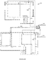
- a powerline network in a household 100 typically has a distributed mains wiring system consisting of one or more ring mains, several stubs or spurs and some distribution back to a junction box 104.
- the household 100 is supplied electrical power from an external line 102.
- the junction box 104 routes the electrical power among ring mains 106, 108, and 110.
- the household 100 further comprises a telephone line network 112.
- the telephone line network 112 does not require a junction box or division among multiple rings. It should be noted that the powerline network is typically more widely distributed to outlets and rooms than the telephone line network 112.
- the outlets most closely located to each other are those on multi-plug strips, and the outlets furthest away from each other are those on the ends of stubs of different ring mains (e.g. power outlets in the first floor and the second floor). Communications between these furthest outlets typically pass through the junction box 104. In some PLC systems, it may be difficult to pass communications through the junction box, particularly if they are on different alternating current (AC) phases.
- AC alternating current
- a communications device for simultaneous multi-wideband communications over multiple mediums may include, for example, a powerline, a telephone line, and/or a coaxial cable.
- a communication may be transmitted or received via any of the mediums.
- a communication may be received via a first medium and forwarded in a second medium.
- a third medium may also be available for reception and/or transmission of the communication.
- a multi-network interface device may receive a communication via a powerline and forward the received communication via a telephone line.
- a communication between two multi-network interface devices may be transmitted, in parallel or sequentially, through two or more mediums within a communications network.
- a video signal may be transmitted from a DVD player to a television via both the powerline and a coaxial cable.
- one medium may be used to bridge two portions of another medium.
- a telephone line may be used as a bridge between sections of mains cable or sections on different AC phases in a powerline network.
- the various media may be used in conjunction with multi-wideband communications.
- the multi-widebands include, for example, a lower frequency range below approximately thirty megahertz and a higher frequency range above approximately thirty megahertz. In some embodiments, the lower frequency range is between two megahertz and twenty-eight megahertz while the higher frequency range is between fifty megahertz and three hundred megahertz.
- the lower frequency band may be conducted via the powerline, and the higher frequency band may be conducted via the powerline and/or another medium such as a telephone wire or coax cabling.
- a single media may be used for communications using both lower and higher frequency ranges.
- higher frequency signals may be moved to another frequency range by mixing, for example to take the signal to above an existing service on the wire, such as in the case of a coaxial cable that already caries analog or digital television information.
- the higher frequency band may be moved, for example, between 1.2 gigahertz and 1.45 gigahertz or between 1.55 gigahertz and 1.8 gigahertz.
- a portion of the higher frequency band may be above 2 gigahertz.
- a signal in the higher frequency bands may comprise an ultra-wideband signal at least 500 megahertz wide.
- the single reference design is optionally a single unit that comprises filters and other components configured to enable connection to different mediums and passing the communications over these mediums.
- the single reference design may comprise multiple interfaces configured to communicate over telephone line, powerline, and/or coaxial cable.
- the single reference design may further allow the different mediums to share a single media access control (MAC) address.
- the single reference design may be powered via the powerline communications interface.
- communications may be received and/or transmitted using powerlines and either telephone lines or coaxial cables.
- the single reference design may comprise a single host interface controller configured to communicate with a networked apparatus.
- a powerline communications device comprises a powerline communications interface, a second communications interface, and a processor.
- the powerline communications interface is configured to transmit a message via a powerline.
- the second communications interface is configured to transmit the message via a second medium.
- the processor is configured to determine, in the alternative, whether to transmit the message via the powerline or the second communications interface based on a quality of service metric associated with the powerline network.
- a powerline communications device comprises a network processor and a host interface controller.
- the network processor comprises logic configured to determine whether to alternatively communicate a message via a powerline communications interface or a second communications interface, the second communications interface being configured to communicate via a telephone line or a coaxial cable, both the powerline communications interface and the second communications interface being associated with a same media access control address.
- the host interface controller is configured to be shared by communications received through the powerline communications interface and the second communications interface.
- a network comprises a first section of mains cable configured to provide AC power, a second section of mains cable configured to provide AC power and connected to the first section of mains cable via a junction box, a telephone network, a first device configured to receive a message via the first section of mains cable and forward the message via the telephone network, and a second device configured to receive the message from the first device via the telephone network, and to forward the message via the second section of mains cable.
- a method comprises generating a message; transmitting the message via a first section of mains cable connected to a second section of mains cable via a junction box; receiving the message at a first device; transmitting the message from the first device, via a telephone line or a coaxial cable; receiving the message from the first device, at a second device; and transmitting the message from the second device, via the second section of mains cable.
- a network comprises a first section of mains cable configured to provide AC power, a second section of mains cable configured to provide AC power and connected to the first section of mains cable via a junction box, a coaxial cable network, a first device configured to receive a message via the first section of mains cable and forward the message via the coaxial cable network, and a second device configured to receive the message from the first device via the coaxial cable network, and to forward the message via the second section of mains cable.
- powerline will be used herein to refer to low voltage household or commercial mains distribution cabling (typically 100-240 V AC power) or any other distributed electrically conductive AC cabling that is capable of passing power to appliances connected to it.
- powerline technology will be used herein to refer to a specification that when implemented as a series of network interface devices connected to a powerline, enables the devices to bidirectionally communicate with each other using signals superimposed on the power distribution AC voltages also present on the powerline.
- multi-network interface device will be used herein to describe an apparatus that implements either fully or partially, at least two communications technologies, such as a powerline technology, a telephone line technology, or a coaxial cable technology to enable the apparatus to communicate with other devices connected via the same communications technology (such as a powerline, telephone line, or coaxial cable) to a network, regardless of whether or not the apparatus is integrated with other apparatuses or functions within a single enclosure.
- the multi-network interface device may be a powerline communications device having additional communications interfaces for communicating via a phone line and/or a coaxial cable.
- a frequency band used in the multi-network interface device comprising a frequency of less than about 30 MHz, will be known herein as a "low band(s)".
- a frequency band(s) used in the powerline communication devices, telephone line communications devices, and coaxial cable communications devices whose frequency is greater than about 30 MHz will be known herein as "high band(s)."
- signal path will be used to refer to the path of a signal transmitted or received from a network apparatus to the powerline, telephone line or coaxial cable.
- Frequency bands are to characterize frequency bands that do not use, except incidentally, the same frequencies for communication data or commands.
- Frequency bands may be separate but interleaved, e.g., overlapping.
- simultaneous is used herein with respect to communicating data to indicate that at least part of first data or commands are communicated using a first frequency band and/or medium at the same time as at least part of second data or commands are communicated using a second frequency band and/or medium.
- simultaneous transmission is contrasted with systems that alternate or interleave the use of frequency ranges, one frequency range after the other or hopping from one frequency range to the other frequency range while not using both frequency ranges at the same moment.
- independent is used herein with respect to data transmitted to indicate that data transmitted using one frequency band does not depend on data transmitted using another frequency band.
- Independent data transmission can include, for example, data sent to or received from different locations.
- Data in which alternative bits are transmitted using different frequencies is not independent because the bits are dependent on each other to form a useful byte.
- Data transmitted in a first frequency band and including communication setup information, decryption keys, communication commands, or the like is considered independent from data sent in a second frequency band, even when the receipt or processing of the data sent in the second frequency band may use the data in the first frequency band. This is because, transmission of the communication setup information, decryption keys, communication commands, or the like does not depend on the data sent in the second frequency band.
- wideband is used herein to refer to a frequency band or range used by a powerline, telephone line, or coaxial cable technology signal, characterized by having a bandwidth of greater than, or equal to, about 5 MHz from the first (lowest) frequency to the last (highest) frequency of the band irrespective of the presence of notches.
- wideband may have bandwidths of at least 5, 7, 10, 12, 15, 20, 100, 250 or 500 MHz.
- a wideband may include many different carrier channels used to convey data.
- widebands include more than 25, 50, 100, 250, 500, or 1000 data carrier frequencies with or without CDMA sequences.
- Various embodiments of the invention may make use of wide or narrow frequency bands.
- section of mains cable is used herein to refer to various sections of cabling in a typical AC electrical wiring system in a home or building or dwelling.
- the various sections may be separated from each other by the electrical distribution means, such as a junction box, fuse box, surge protector, residual current detector, or the like.
- An individual section of mains cable may be on a different AC phase than other sections of mains cable within the dwelling.
- the section of mains cable may comprise two or three core class cables with or without shielding.
- the AC electrical wiring system may transfer electricity having a voltage of approximately 110 Volts, 240 Volts, or other standard voltage levels.
- the section of mains cable may comprise, at least in part, a ring main or loop.
- the section of mains cable may comprise, at least in part, a spur that may be part of a branch-based arrangement.
- Some embodiments of the communications network comprise a plurality of nodes of which some employ a multi-network interface device that enables simultaneous and/or independent communication over two or more mediums.
- a first frequency band optionally comprises frequencies of less than 30 MHz and the other frequency band(s) comprise frequencies of greater than 30 MHz.
- both a first and a second frequency band may comprise frequencies greater than 30 MHz. Because of the multiple frequency bands can be in different ranges, communications can be optimized for each of the mediums such that the trade-off between cost, coverage, and throughput will be superior to that achieved by a network comprising a single medium.
- the computing network comprising powerlines, telephone lines, and/or coaxial cable provides inter-operability with prior art powerline technologies by also supporting communication between multi-medium nodes and single medium nodes (that communicate via a single medium (e.g. powerline).
- a single medium e.g. powerline
- the multi-network interface device may be part of an external modem apparatus or embedded within another apparatus (e.g. computer, television, etc.). However, regardless of the manner in which the multi-network interface device is included within a network node, the device remains connected to electrically conductive cabling (that passes AC power) and is capable of transmitting data across the cabling using the low and/or high bands. Further, the multi-network interface device is capable of communicating over more than one medium (e.g. telephone line, coaxial cable, or powerline).
- medium e.g. telephone line, coaxial cable, or powerline
- the multi-network interface device typically employs an analog signal separation device configured to isolate data communication paths from AC power transmission, prior art telephone line communication, and/or prior art coaxial cable communication, to an apparatus.
- an analog signal separation device configured to isolate data communication paths from AC power transmission, prior art telephone line communication, and/or prior art coaxial cable communication, to an apparatus.
- One of the most efficient ways of providing this isolation is by high-pass filtering or band-pass filtering whilst minimizing out-of band signals in the low band.
- high band signals may be filtered using high linearity components and low band signals may be filtered using analog low-pass smoothing or anti-aliasing. It may not be necessary to perform the isolation on both receiver and transmitter signal paths (depending on the specifications of the analog components and the modulation techniques employed therein).
- Signals in the high band and the low band can use the same or different modulation techniques (e.g. Orthogonal Frequency Division Multiplexing (OFDM), and/or Code Division Multiple Access (CDMA)) or time division schemes to facilitate co-existence and/or bi-directional communication.
- OFDM Orthogonal Frequency Division Multiplexing
- CDMA Code Division Multiple Access
- the low band employs a modulation scheme that is inter-operable with one of the existing powerline modem standards or proposals, whilst the high band on the powerline is used for performance expansion beyond previous standards or in other mediums.
- Data and/or control commands can be passed through one or both of the mediums simultaneously and via a plurality of multi-network interface devices in the form of a repeater (e.g., relay) network.
- a repeater e.g., relay
- different types of signals are communicated in different frequency bands.
- communication setup information, node discovery signals, path discovery signals, encryption or decryption keys, communication commands, and/or other types of command and control signals are communicated in a first frequency band while other types of data (e.g., non-command and control) are communicated in a second frequency band.
- the other types of data communicated in the second frequency band may include video, audio, and/or text, etc.
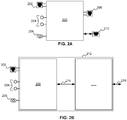
- FIG. 2A is a diagram of an exemplary multi-network interface device 200 comprising a plurality of interfaces for communicating over various mediums.
- the exemplary multi-network interface device 200 may be a separate device, such as an adapter, or embedded into a network apparatus such as a television, stereo, DVD player, personal computer, or the like.
- the multi-network interface device 200 may comprise one or more communications interfaces including a phone line interface 202, a powerline interface 204, and/or a coaxial cable interface 206.
- the communications interfaces are each configured to communicate over their respective mediums.
- the multi-network interface device 200 may further comprise one or more interfaces for communication with an apparatus connected to the multi-network interface device 200.
- the multi-network interface device 200 comprises a second set of communications interfaces including a second phone line interface 208 and an Ethernet interface 210 configured to connect to telephone and an Ethernet network apparatus, respectively.
- the single reference design is optionally a single device that comprises filters and other components configured to enable connection to different mediums and passing the communications over these mediums.
- the single reference design may comprise multiple interfaces configured to communicate over telephone line, powerline, and/or coaxial cable.
- the single reference design may further allow the different mediums to share a single media access control (MAC) address.
- the single reference design may be powered via the powerline communications interface.
- the single reference design may comprise a single host interface controller configured to be shared by communications using the various mediums.
- the telephone interface 202 is configured to communicate over a telephone line network.
- the telephone interface may, in addition to communicating high band signal(s), simultaneously communicate voice signals, DSL signals (including ADSL and VDSL signals), Home Phoneline Networking Alliance (HPNA)-compatible signals, and/or the like. Additionally, the telephone line may already carry these types of signals generated by other sources in other locations.
- DSL signals including ADSL and VDSL signals
- HPNA Home Phoneline Networking Alliance
- the powerline interface 204 may comprise an interface configured to receive electrical power via a powerline.
- the powerline interface 204 may comprise a male and/or female connector.
- the coaxial cable interface 206 is configured to communicate via a coaxial cable network.
- the coaxial cable interface may, in addition to communicating high band communication signal(s), also communicate DSL signals, Data Over Cable Service Interface Specification (DOCSIS)-compatible signals, television broadcast signals (including cable television and/or digital television signals), Multimedia over Coax Alliance (MoCA)-compatible signals, Satellite L-Band signals, and/or the like. Additionally, the coaxial cable may already carry these types of signals generated by other sources in other locations.
- DOCSIS Data Over Cable Service Interface Specification
- MoCA Multimedia over Coax Alliance
- the second telephone interface 208 is configured to communicate a signal between the multi-network interface device 200 and a device.
- the second telephone interface 208 may communicate with a telephone or a DSL modem.
- the multi-network interface device 200 may comprise a second coaxial cable interface 206 and/or a second powerline interface 204.
- Second telephone interface 208 may be connected to a telephone and be used to communicate a telephone call.
- the Ethernet interface 210 is one example of a host interface and is configured to communicate a signal between the multi-network interface device 200 and a device configured to communicate over an Ethernet connection.
- the Ethernet interface may, for example, be connected to a personal computer, media player, or WiFi modem.
- the Ethernet interface 210 may be part of a device compatible with the Universal Plug 'n Play (UPnP) standard, Digital Living Network Alliance (DLNA) standard, or the like.
- UPN Universal Plug 'n Play
- DLNA Digital Living Network Alliance
- the communications signal may travel on one or more of the mediums to reach the multi-network interface device 200 from another node on the network.
- the multi-network interface device 200 may be configured to determine the medium on which to transmit the communications signal based on a Quality of Service (QoS) metric associated with each medium.
- QoS Quality of Service
- the QoS metric may measure network latency, network throughput, available bandwidth, or the like.
- the multi-network interface device 200 may vary which medium is used to transmit signals if the QoS metric changes over time.
- Signals are received at one of the interfaces (telephone line interface 202, the powerline interface 204, the coaxial cable interface 206, the second telephone line interface 208, and/or the Ethernet interface 210) where they may be filtered, converted, frequency shifted, modulated, mixed, or otherwise modified the signal to generate a desirable output signal.
- the output signal may be transmitted via any of the interfaces including the telephone line interface 202, the powerline interface 204, the coaxial cable interface 206, the second telephone line interface 208, and/or the Ethernet interface 210.
- the multi-network interface device 200 is associated with a single media access control (MAC) address. That is, communications received via any of the mediums may be addressed to the same MAC address.
- the multi-network interface device 200 may be associated with two or more MAC addresses and/or have two or more Ethernet interfaces 210.
- the multi-network interface device 200 may comprise a router and routing table, a switch, or the like.
- the signal may substantially "pass through" the communication device 200.
- the multi-network interface device 200 may be connected to the telephone line via the telephone line communications interface 202.
- telephone line connections typically occur less frequently than other connections in a home, a homeowner may wish to install a telephone in the same telephone line connection.
- the homeowner may install the multi-network interface device 200 while still being able to use the same telephone line connection for a telephone.
- FIG. 2B is a diagram of an exemplary apparatus 212 comprising an embedded multi-network interface device 200 having a plurality of interfaces for communicating over various mediums, according to various embodiments.
- the apparatus 212 comprises the multi-network interface device 200, a host subsystem 214, a host interface 216, and an apparatus interface 218.
- the apparatus 212 may comprise a network apparatus such as a set top box, a DSL Home Gateway, a television set, a DVD player, a kitchen appliance (e.g. a refrigerator, microwave, stove, oven, etc.), a wireless access point, a computing device, a data storage device, a stereo, or the like.
- the host subsystem 214 comprises the prior art hardware and/or software included in the network apparatus, e.g., the television receiver or the DVD reader.
- the host interface 206 comprises a communications interface between the multi-network interface device 200 and host subsystem 214.
- the apparatus interface 218 is an output or input of the host subsystem 214 as known in the prior art.
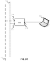
- FIG. 2C is a diagram of an exemplary multi-network interface device 200 connected to a separate network apparatus 220.
- the multi-network interface device 200 is connected to a powerline 106 and a telephone line 112, via the powerline interface 204 and the telephone line interface 202, respectively.
- the multi-network interface device 200 is also connected to the network apparatus 220 via a host interface 216 to the network apparatus 220.
- One example of the host interface 216 is the Ethernet interface 210.
- the network apparatus 220 comprises a laptop computer.
- the network apparatus 220 may comprise a set top box, a DSL Home Gateway, a television set, a DVD player, a kitchen appliance (e.g. a refrigerator, microwave, stove, oven, etc.), a wireless access point, a computing device, a data storage device, a stereo, or the like.
- the host interface 216 is configured to communicate directly with a network apparatus and to act as a first interface between the network apparatus and the rest of the network. In comparison with other interfaces of the multi-network interface device 200, the host interface 216 is optionally connected to just the network apparatus 220 rather than a network including multiple devices and/or mediums. Typically, the host interface 216 is configured to provide communications between the network apparatus 220 and the multi-network interface device 200 over a single medium. As is illustrated in FIGs. 2B and 2C , the host interface 216 may be embedded within an apparatus 212 or may be an interface between the separate devices (e.g., multi-network interface device 200 and the network apparatus 220).
- the host interface 216 is one example of a "host interface.”
- a host interface may be a boundary between two entities that exchange data using Ethernet class II packets and interfaces associated with a direct application endpoint or start point.
- Ethernet class II packets include IEEE 802.3 packets with or without IEEE 802.2 (Logical Link Control (LLC)), IEEE 802.1H (Sub Network Access Protocol (SNAP)) extensions and/or Virtual Local Area Network (VLAN) tagging.
- LLC Logical Link Control
- SNAP Sub Network Access Protocol
- VLAN Virtual Local Area Network
- host interface 216 examples include: Ethernet 10/100/1000, Media Independent Interface (MII), Gigabit Media Independent Interface (GMII), Peripheral Component Interconnect (PCI), Host Processor Interface, Universal Serial Bus (USB) 2.0, Firewire, Peripheral Component Interconnect Extended (PCI-X), Peripheral Component Interconnect Express (PCIe), Universal Asynchronous Receiver Transmitter (UART), Service Provider Interface (SPI), or the like.
- MII Media Independent Interface
- GMII Gigabit Media Independent Interface
- PCI Peripheral Component Interconnect
- USB Universal Serial Bus
- Firewire Peripheral Component Interconnect Extended
- PCIe Peripheral Component Interconnect Express
- UART Universal Asynchronous Receiver Transmitter
- SPI Service Provider Interface
- Examples of host interface 216 associated with a direct application end point or start point include: Serial Advanced Technology Attachment (SATA) I/II/III, Universal Serial Bus (USB) 2.0, Inter-Integrated Circuit Sound (I2S), Universal Asynchronous Receiver Transmitter (UART), Infrared Data Association (IrDA) protocols, Moving Picture Experts Group (MPEG) Transport Stream (TS), High-Definition Multimedia Interface (HDMI), and Video Graphics Array (VGA).
- SATA Serial Advanced Technology Attachment
- USB Universal Serial Bus
- I2S Inter-Integrated Circuit Sound
- UART Universal Asynchronous Receiver Transmitter
- IrDA Infrared Data Association
- MPEG Moving Picture Experts Group
- TS Transport Stream
- HDMI High-Definition Multimedia Interface
- VGA Video Graphics Array
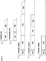
- FIG. 3 includes exemplary communications transmission spectra of three mediums, according to various embodiments. Any or all of the mediums (powerlines, telephone lines, and/or coaxial cable) may be present in a network.
- the various frequency bands depicted in FIG. 3 may comprise widebands and/or narrow bands.
- Other, different, communications spectra may be used in alternative embodiments.
- the x-axis represents frequency.
- a communications transmission spectrum as may be associated with a powerline is shown.
- the spectrum 302 comprises a low band 304 and a high band 306.
- the low band 304 may comprise frequency bands below approximately thirty megahertz.
- the low band 304 may include base band powerline communications frequencies as described in the HomePlug AV standard (i.e. two megahertz to thirty megahertz).
- the high band 306 comprises one or more frequency bands above approximately thirty megahertz (e.g. fifty megahertz to three hundred megahertz).
- the high band 306 may comprise a frequency band above one gigahertz.
- use of the high band 306 is optional. Communications signals may be transmitted on the powerline in both the low band 304 and the high band 306 simultaneously and/or independently.
- a communications transmission spectrum as may be associated with a telephone line is shown.
- the spectrum comprises a lower frequency band 310 on which communications of the prior art are transmitted. These communications include voice telephony, ADSL, VDSL, HPNA, and the like.
- the high band 306, used in powerline communications, may also be used on the telephone line.
- a frequency band 314, for example, is currently associated with DSL standards and DOCSIS.
- a frequency band 316 is associated with television broadcasts, cable television, and digital television.
- Frequency band 318 is associated with the MoCA standard and the Satellite L-Band between three hundred ninety megahertz and 1.55 gigahertz.
- the communication signal associated with a home network is transmitted at a higher frequency than the satellite L-band, namely, above 1.55 gigahertz, in a high band 320.
- the high band 320 may be associated with a bandwidth of approximately two hundred fifty megahertz.
- a service provider can fully exploit the L-band without interference caused by the home network.
- placing the high band 320 above the other frequencies used by a service provider may reduce the likelihood that content, such as downloaded films or television shows, provided by the service provider may be hacked or otherwise stolen by a homeowner.
- the communication signal associated with the home network is communicated at least partially within the L-band in high band 324.
- the high band 324 ranges from approximately one gigahertz to approximately 1.5 gigahertz.
- the high band 324 may range from approximately 1.2 gigahertz and 1.45 gigahertz.
- the high band 324 may use frequencies not lower than 1.1 gigahertz, 1.2 gigahertz, 1.3 gigahertz, 1.4 gigahertz, 1.5 gigahertz, 1.6 gigahertz, 1.7 gigahertz, 1.8 gigahertz, 1.9 gigahertz and 2.0 gigahertz.
- Frequency ranges included in some embodiments are described in nonprovisional U.S. patent application No. 11/536,539 filed September 28, 2006 and entitled "Multi-Wideband Communications over Powerlines.”
- the signal transmit in frequency band 318 and/or the signal transmit in high band 324 maybe encrypted or otherwise protected.
- frequency band 316 associated with television broadcasts, cable television, and digital television is not being used, the communication signal associated with the home network is communicated at least partially within frequency band 328. At least a portion of the frequency band 328 includes frequencies between 50 MHz and 300 MHz.
- FIGs. 4-8 and 10-12 depict various embodiments of multi-network interface device 200.
- the depicted embodiments support communications via a powerline and a telephone line, and via a powerline and a coaxial cable. It is understood that these embodiments may be modified by those skilled in the art to support communications over any combination of the three mediums.
- a multi-network interface device 200 may support communications via a telephone line and a coaxial cable, but not a powerline.
- the embodiments shown may comprise one or more integrated circuit.
- FIG. 4 is a block diagram of a first circuit embodiment of the multi-network interface device 200.
- the multi-network interface device 200 is configured to provide communications interfaces for a powerline and a telephone line.
- a communication may be received and/or transmitted via the telephone line interface 202 and/or the powerline interface 204.
- the telephone line is passively shared with prior art telephone signals.
- the multi-network interface device 200 processes a communications signal received through the telephone line interface 202 and/or powerline interface 204 and provides a resulting output signal via an optional Ethernet interface 210, and vice-versa.
- Ethernet interface 210 is optionally coupled to a network apparatus such as a television set, DVD player, media player, personal computer, speaker, stereo, video game console, personal digital assistant, or the like.
- the multi-network interface device 200 may receive the communications signal from one of the telephone line interface 202 or the powerline interface 204 and transmit the communications signal via the other telephone line interface 202 or the powerline interface 204.
- the telephone line may be used to provide redundancy in a mesh or ad-hoc network.
- a signal is communicated via the telephone line interface 202. These signals may be communicated in the high band 306.
- the signal path from the telephone line interface 202 to the Ethernet interface 210 comprises a surge protector 402, an inductive coupler 404, a high pass filter 406, a network processor 412, and a host interface controller 414.
- the high pass filter 406 may allow only frequencies above approximately thirty megahertz to pass.
- the surge protector 402, the inductive coupler 404, and the high pass filter 406 collectively provide signal communications without significantly impacting services existing on lower frequencies.
- a signal is communicated via the powerline interface 204.
- the signal may be communicated via the low band 304 and/or the high band 306.
- the signal path from the powerline interface 204 to the Ethernet interface 210 comprises an inductive coupler 408, and, depending on the frequency band of the signal, the high pass filter 406 and/or a low pass filter 410.
- the inductive coupler 408, the high pass filter 406 and the low pass filter 410 collectively provide signal communications without significantly impacting prior art signals at lower frequencies.
- the powerline interface 204 may not be configured to communicate via the high band 306. In these embodiments, the high pass filter 406 is optional.
- the network processor 412 and the host interface controller 414 are shared by the signal paths associated with the powerline interface 204 and the telephone line interface 202.
- the network processor 412 comprises processing circuitry to remove noise, amplify the signal, and/or convert an analog signal to a digital signal or vice-versa.
- the network processor 412 may comprise two or more analog front ends (AFE). One of the AFEs is configured to receive and/or transmit a communications signal on the high band 206 and the other of the AFEs is configured to receive and/or transmit a communications signal on the low band 304.
- a communication signal received via the high band 306 passes through the high pass filter 406 and a high frequency AFE 416
- a communication signal received via the low band 304 passes through the low pass filter 410 and a low frequency AFE 418.
- the network processor 412 may further comprise a line driver, programmable gain amplifier, an analog-to-digital converter, and/or a digital-to-analog converter. Possible configurations of the network processor 412 are described in greater detail in nonprovisional U.S. patent application 11/536,539 filed September 28, 2006 and entitled "Multi-Wideband Communications over Powerlines.” Logic within the network processor may determine whether to transmit a communication signal via a certain communications interface based on a quality of service metric of the communications network or a purpose of the communication signal. The network processor 412 may be compatible with the HomePlug AV standard or other standards associated with powerline communications, telephone line communications, or coaxial cable communications. Network processor 412 is optionally configured to process prior art telephone signals, e.g., if the multi-network interface device 200 is included in a telephone.
- the host interface controller (ICONT) 414 allows for communication of data between the Ethernet interface 210 and the network processor 412.
- the ICONT 414 may implement an Ethernet controller as specified by IEEE 802.3.
- the ICONT 414 includes the Physical and Data Link layers as defined in the seven layer OSI reference model for standardizing computer-to-computer communications.
- ICONT 414 may implement a TCP/IP stack that includes the Network, Transport and Application layers of the OSI reference model.
- the multi-network interface device 200 may receive power via the powerline interface 204.
- ICONT 414 is optionally included within network processor 412, host interface PCI driver, or the like.
- FIG. 5 is a block diagram of a second embodiment of the multi-network interface device 200.
- the multi-network interface device 200 is configured to communicate a first signal via the low band 304 over a powerline and to communicate a second signal via the high band 306 over a telephone line.
- the multi-network interface device 200 additionally comprises a second telephone line interface 208.
- the second telephone line interface 208 may be used to communicate voice, ADSL, VDSL, or HPNA signals within band 310.
- an optional second inductive coupler 502 may be placed between the surge protector 402 and the inductive coupler 404.
- the second inductive coupler 502 is coupled to an optional low pass filter 504 to isolate the signal within the band 310 from other communications signals communicated within the high band 306.
- the low pass filter 504 may pass frequencies below approximately thirty megahertz.
- Another surge protector 402 may be placed between the low pass filter 504 and the second telephone line interface 208.
- a user may connect a non-network apparatus such as a telephone, DSL modem, or the like to the second telephone line interface 208.
- the first telephone line interface 202 and the second telephone line interface 208 are connected by a direct pass-through connection.
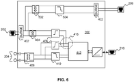
- FIG. 6 is a block diagram of a third embodiment of a multi-network interface device 200.
- the multi-network interface device 200 is configured to communicate a first signal via the low band 304 over a powerline, to communicate a second signal via the high band 306 over the powerline, and optionally to communicate the second signal or a third signal via the high band 306 over a telephone line.
- the multi-network interface device 200 comprises a second telephone interface 208 from which a fourth signal, in band 310, maybe communicated as discussed in connection with FIG. 5 .
- the multi-network interface device 200 comprises a network processor 412 having a single high frequency AFE 416 configured to receive or transmit signals communicated via the high band 306 over both the powerline and the telephone line.
- the single high frequency AFE 416 optionally includes passive sharing of the powerline and the phone line. As such, the single high frequency AFE 416 can only receive or only transmit one signal at any one time.
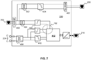
- FIG. 7 is a block diagram of a fourth embodiment of the multi-network interface device 200.
- the embodiment of multi-network interface device 200 illustrated in FIG. 7 is substantially similar to the multi-network interface device 200 illustrated in FIG. 6 except for a dual high frequency AFE 702.
- the dual high frequency AFE 702 includes two separate inputs configured to independently and simultaneously communicate signals in the high band 306 and through both the telephone line interface 202 and the powerline interface 204.
- FIG. 8 is a block diagram of a fifth embodiment of the multi-network interface device 200.
- the multi-network interface device 200 is configured to communicate between an optional Ethernet interface 210, a powerline interface 204, and a coaxial cable interface 206. The communication may pass between any two or all three of these interfaces.
- the multi-network interface device 200 may communicate over a powerline using the low band 304 and over coaxial cable using either band 320 or band 324.
- the powerline signal path may be configured to support communications over the high band 306.
- the multi-network interface device 200 may support communications between the power line interface 204 and the coaxial cable interface 206.
- the signal path from the powerline interface to the Ethernet interface 210 is further discussed herein, for example, in connection with FIG. 4 .
- the signal path from the coaxial cable interface 206 comprises an inductive coupler 802, a band pass filter 804, a receiving signal path, and transmitting signal path, a local oscillator 812, a low pass filter 814, the network processor 412, and the ICONT 414. From the ICONT 414, the signal may be communicated to the Ethernet interface 210 and/or the powerline interface 204.
- the receiving signal path comprises a low noise amplifier 806, a band pass filter 808, and an optional down converter mixer 810.
- the transmitting signal path comprises an optional up converter mixer 816, a band pass filter 818, and a programmable amplifier 820.
- the network processor 412 and the ICONT 414 may be shared with the powerline signal path.
- the coaxial cable may carry signals at frequencies above one gigahertz, as described herein, for example, in connection with FIG. 3 .
- the network processor 412 may be configured to process signals having frequencies within low band 304 and high band 306. Therefore, these signals may be shifted between the high band 306 and the high band 320 or the high band 324 along the coaxial cable signal path using the up converter mixer 816 or the down converter mixer 310, respectively.
- clock error on the coaxial cable may be communicated over the powerline using the powerline interface 204
- the inductive coupler 802 and the band pass filter 804 collectively enable signal communications without impacting prior art services on lower frequencies.
- the low-noise amplifier 806 may amplify a signal received via the coaxial cable interface 206 based on a control signal received from the network processor 412. The signal may then pass through an optional second band pass filter 808 before entering the down converter mixer 810.
- the down converter mixer 810 is controlled by the local oscillator 812, which is, in turn, controlled by the network processor 412.
- the down converter mixer 810 is configured, based on the received signal, to generate two lower frequency sidebands.
- the low pass filter 814 passes one of the two lower frequency sidebands. The passed lower frequency sideband is then processed by the network processor 412.
- An output signal from the network processor 412 via the coaxial cable interface 206 optionally passes through the low pass filter 814, the up converter mixer 816, a band pass filter 818, and a programmable gain amplifier 820.
- the up converter mixer 816 is controlled by the local oscillator 812 and generates two side bands.
- the band pass filter 818 isolates one of the sidebands for transmission via the coaxial cable.
- the isolated sideband may be selected based on the presence or absence of satellite L-band signals on the coaxial cable.
- the isolated sideband is then amplified by programmable amplifier 820.
- the signal passes through the band pass filter 804 and the inductive coupler 802 upon leaving the transmission path.
- FIG. 9 depicts frequency bands associated with the signal used by the fifth integrated circuit embodiment 200 depicted in FIG. 8 , according to various embodiments when the signal is communicated via the coaxial cable.
- Spectra 902, 904, and 906 depict frequency characteristics of a signal received by the multi-network interface device 200 along the receiving signal path.
- Spectra 908, 910, and 912 depict frequency characteristics of the signal transmitted by the multi-network interface device 800 along the transmitting signal path.
- the signals are communicated via the coaxial cable using high band 324. In other embodiments, the signals may be received and/or transmitted over high band 320.
- a signal within the high band 324 is received by the coaxial cable interface 206.
- the down converter mixer 810 In the receiving signal path, the down converter mixer 810 generates two sidebands, in the high band 306 and in another band 914, based on the received signal as depicted in spectra 904. At least one of these sidebands may be within high band 306 or low band 304.
- the lower frequency sideband is shown to be within high band 306.
- the low pass filter 814 isolates the sideband in high band 306 shown in spectrum 906, which can be processed by network processor 412.
- the network processor 412 To transmit a signal via the coaxial cable interface 206, the network processor 412 generates the signal in the high band 306, as shown in spectrum 908.
- the up converter mixer 816 generates two side bands from the generated signal as shown in spectrum 910. In the embodiment shown, at least one of these sidebands is within high bands 320 and 324 as described herein, at least, in connection with FIG. 3 . Other embodiments may generate sidebands in other frequencies.
- the sideband, e.g. in band 324, to be transmitted via the coaxial cable interface 206 is isolated, as shown in spectrum 912, using the band pass filter 818.
- network processor 412 is configured to directly process and/or generate signals in the high band 324 and/or the high band 320.
- the multi-network interface device 200 may comprise a communications interface is associated with a second media access control address.
- the multi-network interface device 200 may comprise a router or switch. The router may access a router table to route communications and/or messages to an appropriate MAC address.
- FIG. 10 is a block diagram of a sixth circuit embodiment of the multi-network interface device 200, according to various embodiments.
- the multi-network interface device 200 is configured to communicate between an optional host interface 216, a powerline interface 204, and a coaxial cable interface 206.
- the multi-network interface device may communicate via the powerline and/or the host interface 216 as described herein, at least, in connection with FIG. 4 .
- the coaxial cable interface 206 may communicate signals within the frequency band 328 described herein, at least, in connection with FIG. 3 .
- the high pass filter 406 may isolate the signals in frequency band 328 from those present on the coaxial cable in band 314.
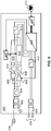
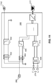
- FIG. 11 is a block diagram of a seventh circuit embodiment of the multi-network interface device 200, according to various embodiments.
- the multi-network interface device 200 is configured to communicate between an optional host interface 216, a powerline interface 204, and a coaxial cable interface 206.
- the multi-network interface device may communicate via the powerline and/or the host interface 216 as described herein, at least, in connection with FIG. 5 .
- the coaxial cable interface 206 may communicate signals within the frequency band 328 described herein, at least, in connection with FIG. 3 .
- the multi-network interface device 200 additionally comprises a second coaxial cable interface 1102.
- the second coaxial line interface 208 maybe used to communicate voice, ADSL, VDSL, or HPNA signals within band 314.
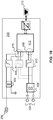
- FIG. 12 is a block diagram of an eighth circuit embodiment of the multi-network interface device 200, according to various embodiments.
- the multi-network interface device 200 is configured to communicate a first signal via the low band 304 over a powerline, to communicate a second signal via the high band 306 over the powerline, and optionally to communicate the second signal or a third signal via the frequency band 328 over a coaxial cable.
- the multi-network interface device may communicate via the powerline and/or the host interface 216 as described herein, at least, in connection with FIG. 6 .
- the coaxial cable interface 206 may communicate signals within the frequency band 328 described herein, at least, in connection with FIG. 3 .
- the multi-network interface device 200 additionally comprises a second coaxial cable interface 1102.
- the second coaxial line interface 208 may be used to communicate voice, ADSL, VDSL, or HPNA signals within band 314.
- FIG. 13 is a flowchart depicting an exemplary method 1300 for communicating within a network, according to various embodiments.
- a multi-network interface device 200 may become known to, and communicate with, other network devices within a communications network. These other network devices may be further instances of multi-network interface device 200 or other network devices known in the art.
- the multi-network interface device 200 may act as a repeater in the network and/or otherwise forward messages to the other network devices via the method 1300.
- the multi-network interface device 200 interrogates the communications network by sending and receiving data packets.
- the powerline interface 204, telephone line interface 202, and/or the coaxial cable interface 206 may be used to send and receive these data packets.
- the interrogation may, in some embodiments, be initiated by network service provider such as a cable provider.
- the interrogation may be configured to determine, for example, types of network devices connected to the communications network, MAC addresses associated with these network devices, which mediums and frequency bands may be used to communicate with each of these network devices, possible bandwidths, and/or the like.
- the interrogation may include obtaining one or more quality of service (QoS) metric.
- QoS metrics may be associated with specific media and/or specific frequency bands.
- multi-network interface device 200 may be able to communication with another network device through more than one media and/or using more than one frequency band.
- the QoS metric may be used to determine which media and/or which frequency bands are preferred for communicating with specific network devices.
- a message is received by the multi-network interface device 200 from another network device or from the Ethernet interface 210.
- the message may be received via an Ethernet cable, the powerline, the telephone line, or the coaxial cable.
- the message may comprise a request for communications, or a video data signal sent from a DVD player to a television.
- a pathway and associated medium for forwarding the message received in step 1304 to another network device is selected. This selection may be based on a QoS requirement, the type of network device to which the message is to be forwarded to, a communication interface associated with the network device, and/or a bandwidth requirement of the message to be sent. This selection may further use information gathered in step 1302. For example, bandwidths and QoS metrics determined in step 1302 may be compared with bandwidth and QoS requirements.
- More than one medium is optionally selected in step 1306. For example, it may be determined that data can be sent via both telephone interface 202 and powerline interface 204 in parallel to achieve a required bandwidth. Alternatively, it may be determined that command and control signals may be sent via powerline interface 204 while high bandwidth video data can be sent via telephone interface 202 and/or a different frequency band of the powerline interface 204.
- the multi-network interface device 200 may select a pathway to a destination. This selection may be made, for example, to avoid passage through a junction box or other pathway associated with a low QoS metric. As such, the selected pathway may include transmitting the received message via the telephone line interface 202 or coaxial cable interface 206, rather than the power line interface 204.
- a step 1308 specific frequency bands associated with the media selected in step 1306 are selected for transmitting the message. For example, if the selected media includes a power line coupled to power line interface 204, then the low band 304 and/or the high band 306 may be selected in step 1308. If the selected media includes a coaxial cable coupled to the coaxial cable interface 206, then the frequency bands 320 and/or 324 may be selected. The selection of frequency bands is typically made based on criteria similar to the criteria used to select media in step 1306. For example, the selection may be made based on comparisons of bandwidth and QoS requirements with metrics determined in step 1302. More than one frequency band may be selected in step 1008. In some embodiments, steps 1306 and 1308 are combined into a single step.
- the message is transmitted via the selected media selected in step 1306 and the frequency bands selected in step 1308.
- the transmission may include using an alternative medium (e.g., the telephone line) and/or shifting the message into another frequency band (e.g., from low band 304 to high band 306).
- FIG. 14 is a flowchart depicting an exemplary method 1400 for bridging between mediums, according to various embodiments.
- bridging between mediums may be performed when there is a section of the network having a low QoS.
- two or more devices communicate the signal across multiple mediums. For example, in some communications networks using a powerline communications network, passing a signal through a junction box to traverse between sections of mains cable is difficult. Therefore, another medium may be used as a bridge between multiple sections of mains cable.
- a signal is generated.
- the signal is associated with one or more destinations.
- the signal is transmitted via a first powerline communications network to a first multi-network interface device 200.
- the first multi-network interface device 200 may be connected to a first section of mains cable.
- the signal is received at the first multi-network interface device 200.
- the signal is shifted into another frequency band for transmission via the telephone line or coaxial cable.
- the signal is transmit from the first multi-network interface device 200 via the telephone line or coaxial cable to a second multi-network interface device 200.
- the signal is received at the second multi-network interface device 200 via the telephone line or coaxial cable.
- the second device may be connected to, for example, a second section of mains cable separated from the first section of mains cable by a junction box.
- the signal is transmitted via the second powerline communications network.
- the signal may be modified in frequency or content by the first or second multi-network interface device 200.
- one of the communications interfaces included in multi-network interface device 200 may be configured to communicate over a wireless network, such as a WiFi network, and comprise a wireless network antenna.
- the multi-network interface device 200 may include a transformer configured to transform AC power received via the powerline to DC power (e.g., 5V, 12V, or 24V) to power a network apparatus.
- the multi-network interface device 200 includes an AC/DC converter.
- Ethernet interface 210 maybe replaced by another computer interface such as a universal serial bus interface, a parallel port interface, a Peripheral Component Interconnect (PCI) interface, an Accelerated Graphics Port (AGP), a wireless interface, and/or other industry standard data interface.
- PCI Peripheral Component Interconnect
- AGP Accelerated Graphics Port
- Some embodiments of the multi-network interface device 200 include external devices that comprise two interfaces configured to communicate via two types of mediums. These devices may or may not include a bypass as described herein, at least, in connection with FIG. 5 .
- One embodiment comprises interfaces configured to communicate via the powerline on a low band and via a telephone line on a high band to one or more host interfaces configured to communicate using Ethernet 10/100/1000, WiFi, UWB, Wireless USB, USB2.0, Firewire, or the like.
- One embodiment comprises interfaces configured to communicate via the powerline on a low band, via the powerline on a high band and via a telephone line on a high band to one or more host interfaces configured to communicate using Ethernet 10/100/1000, WiFi, UWB, Wireless USB, USB2.0, Firewire, or the like.
- One embodiment comprises interfaces configured to communicate via the powerline on a low band and via a coaxial cable on a high band to one or more host interfaces configured to communicate using Ethernet 10/100/1000, WiFi, UWB, Wireless USB, USB2.0, Firewire, or the like.
- One embodiment comprises interfaces configured to communicate via the powerline on a low band, via the powerline on a high band, and via a coaxial cable on a high band to one or more host interfaces configured to communicate using Ethernet 10/100/1000, WiFi, UWB, Wireless USB, USB2.0, Firewire, or the like.
- One embodiment comprises interfaces configured to communicate via the powerline on a low band and via a coaxial cable on a high band using a mixer as described herein, at least, in connection with FIG. 8 to one or more host interfaces configured to communicate using Ethernet 10/100/1000, WiFi, UWB, Wireless USB, USB2.0, Firewire, or the like.
- One embodiment comprises interfaces configured to communicate via the powerline on a low band, via the powerline on a high band, and via coaxial cable on a high band using a mixer as described herein, at least, in connection with FIG. 8 to one or more host interfaces configured to communicate using Ethernet 10/100/1000, WiFi, UWB, Wireless USB, USB2.0, Firewire, or the like.
- Some embodiments of the multi-network interface device 200 include external devices that comprise three interfaces configured to communicate via three types of mediums. These devices may or may not include a bypass as described herein, at least, in connection with FIG. 5 .
- One embodiment comprises interfaces configured to communicate via the powerline on a low band, via a telephone line on a high band, and via a coaxial cable on a high band to one or more host interfaces configured to communicate using Ethernet 10/100/1000, WiFi, UWB, Wireless USB, USB2.0, Firewire, or the like.
- One embodiment comprises interfaces configured to communicate via the powerline on a low band, via the powerline on a high band, via a telephone line on a high band, and via a coaxial cable on a high band to one or more host interfaces configured to communicate using Ethernet 10/100/1000, WiFi, UWB, Wireless USB, USB2.0, Firewire, or the like.
- One embodiment comprises interfaces configured to communicate via the powerline on a low band, via the powerline on a high band, via a telephone line on a high band, and via a coaxial cable on a high band using a mixer as described herein, at least, in connection with FIG. 8 to one or more host interfaces configured to communicate using Ethernet 10/100/1000, WiFi, UWB, Wireless USB, USB2.0, Firewire, or the like.
- Some embodiments of the multi-network interface device 200 include embedded devices that comprise two interfaces configured to communicate via two types of mediums. These devices may or may not communicate over mediums that also have signals for other services in other frequency bands. Examples of these services include DOCSIS, Cable TV, or the like in a coaxial cable modem and/or DSL, Voice, or the like in a DSL Home Gateway device.
- One embodiment comprises interfaces configured to communicate via the powerline on a low band and via a telephone line on a high band to one or more host interfaces such as MII, GMII, PCI, MiniPCI, PCI-X, PCIe, Host Processor Interface, SPI, UART, or the like.
- One embodiment comprises interfaces configured to communicate via the powerline on a low band, via the powerline on a high band, and via a telephone line on a high band to one or more host interfaces such as MII, GMII, PCI, MiniPCI, PCI-X, PCIe, Host Processor Interface, SPI, UART, or the like.
- One embodiment comprises interfaces configured to communicate via the powerline on a low band and via a coaxial cable on a high band to one or more host interfaces such as MII, GMII, PCI, MiniPCI, PCI-X, PCIe, Host Processor Interface, SPI, UART, or the like.
- One embodiment comprises interfaces configured to communicate via the powerline on a low band, via the powerline on a high band, and via a coaxial cable on a high band to one or more host interfaces such as MII, GMII, PCI, MiniPCI, PCI-X, PCIe, Host Processor Interface, SPI, UART, or the like.
- One embodiment comprises interfaces configured to communicate via the powerline on a low band and via a coaxial cable on a high band using a mixer as described herein, at least, in connection with
- FIG. 8 to one or more host interfaces such as MII, GMII, PCI, MiniPCI, PCI-X, PCIe, Host Processor Interface, SPI, UART, or the like.
- One embodiment comprises interfaces configured to communicate via the powerline on a low band, via the powerline on a high band, and via a coaxial cable on a high band using a mixer as described herein, at least, in connection with FIG. 8 to one or more host interfaces such as MII, GMII, PCI, MiniPCI, PCI-X, PCIe, Host Processor Interface, SPI, UART, or the like.
- Some embodiments of the multi-network interface device 200 include embedded devices that comprise three interfaces configured to communicate via three types of mediums. These devices may or may not communicate over mediums that also have signals for other services in other frequency bands. Examples of these services include DOCSIS, Cable TV, or the like in a coaxial cable modem and/or DSL, Voice, or the like in a DSL Home Gateway device.
- One embodiment comprises interfaces configured to communicate via the powerline on a low band, via a telephone line on a high band, and via a coaxial cable on a high band to one or more host interfaces to one or more host interfaces such as MII, GMII, PCI, MiniPCI, PCI-X, PCIe, Host Processor Interface, SPI, UART, or the like.
- host interfaces such as MII, GMII, PCI, MiniPCI, PCI-X, PCIe, Host Processor Interface, SPI, UART, or the like.
- One embodiment comprises interfaces configured to communicate via the powerline on a low band, via the powerline on a high band, via a telephone line on a high band, and via a coaxial cable on a high band to one or more host interfaces to one or more host interfaces such as MII, GMII, PCI, MiniPCI, PCI-X, PCIe, Host Processor Interface, SPI, UART, or the like.
- host interfaces such as MII, GMII, PCI, MiniPCI, PCI-X, PCIe, Host Processor Interface, SPI, UART, or the like.
- One embodiment comprises interfaces configured to communicate via the powerline on a low band, via a telephone line on a high band, and via a coaxial cable on a high band using a mixer as described herein, at least, in connection with FIG. 8 to one or more host interfaces to one or more host interfaces such as MII, GMII, PCI, MiniPCI, PCI-X, PCIe, Host Processor Interface, SPI, UART, or the like.
- One embodiment comprises interfaces configured to communicate via the powerline on a low band, via the powerline on a high band, via a telephone line on a high band, and via a coaxial cable on a high band using a mixer as described herein, at least, in connection with FIG. 8 to one or more host interfaces to one or more host interfaces such as MII, GMII, PCI, MiniPCI, PCI-X, PCIe, Host Processor Interface, SPI, UART, or the like.
- Some embodiments of the multi-network interface device 200 include external repeater devices that comprise two or three interfaces configured to communicate via two or three types of mediums. These devices may or may not include a bypass as described herein, at least, in connection with FIG. 5 .
- One embodiment is configured to repeat signals between the powerline on a low band and the telephone line on a high band.
- One embodiment is configured to repeat signals between the powerline on a low band, the power line on a high band, and the telephone line on a high band.
- One embodiment is configured to repeat signals between the powerline on a low band and the coaxial cable on a high band.
- One embodiment is configured to repeat signals between the powerline on a low band, the power line on a high band, and the coaxial cable on a high band.
- One embodiment is configured to repeat signals between the powerline on a low band and the coaxial cable on a high band using a mixer as described herein, at least, in connection with FIG. 8 .
- One embodiment is configured to repeat signals between the powerline on a low band, the power line on a high band, and the coaxial cable on a high band using a mixer as described herein, at least, in connection with FIG. 8 .
- One embodiment is configured to repeat signals between the powerline on a low band, the telephone line on a high band, and the coaxial cable on the high band.
- One embodiment is configured to repeat signals between the powerline on a low band, the power line on a high band, the telephone line on a high band, and the coaxial cable on the high band.
- One embodiment is configured to repeat signals between the powerline on a low band, the telephone line on a high band, and the coaxial cable on a high band using a mixer as described herein, at least, in connection with FIG. 8 .
- One embodiment is configured to repeat signals between the powerline on a low band, the power line on a high band, the telephone line on a high band, and the coaxial cable on a high band using a mixer as described herein, at least, in connection with FIG. 8 .
- Some embodiments of the multi-network interface device 200 comprise two or three network interfaces and a host interface comprising an I2S or Sony/Philips Digital Interconnect Format (SPDIF) compliant interface for transfer of an audio stream.
- a host interface comprising an I2S or Sony/Philips Digital Interconnect Format (SPDIF) compliant interface for transfer of an audio stream.
- SPDIF Sony/Philips Digital Interconnect Format
- One embodiment comprises interfaces configured to communicate via the powerline on a low band and the telephone line on a high band to the host interface.
- One embodiment comprises interfaces configured to communicate via the powerline on a low band, via the powerline on a high band, and the telephone line on a high band to the host interface.
- One embodiment comprises interfaces configured to communicate via the powerline on a low band and the coaxial cable on a high band to the host interface.
- One embodiment comprises interfaces configured to communicate via the powerline on a low band, via the powerline on a high band, and the coaxial cable on a high band to the host interface.
- One embodiment comprises interfaces configured to communicate via the powerline on a low band, and via the coaxial cable on a high band using a mixer as described herein, at least, in connection with FIG. 8 to the host interface.
- One embodiment comprises interfaces configured to communicate via the powerline on a low band, via the powerline on a high band, and via the coaxial cable on a high band using a mixer as described herein, at least, in connection with FIG. 8 to the host interface.
- One embodiment comprises interfaces configured to communicate via the powerline on a low band, the telephone line on a high band to the host interface, and the coaxial cable on the high band.
- One embodiment comprises interfaces configured to communicate via the powerline on a low band, via the powerline on a high band, via the telephone line on a high band to the host interface, and via the coaxial cable on a high band.
- One embodiment comprises interfaces configured to communicate via the powerline on a low band, via the telephone line on the high band, and via the coaxial cable on a high band using a mixer as described herein, at least, in connection with FIG. 8 to the host interface.
- One embodiment comprises interfaces configured to communicate via the powerline on a low band, via the powerline on a high band, via the telephone line on the high band, and via the coaxial cable on a high band using a mixer as described herein, at least, in connection with FIG. 8 to the host interface.
Claims (15)
- Powerline-Communications- (Datenübertragung über Stromleitung) Vorrichtung, die umfasst:- eine Powerline-Communications-Schnittstelle (204), die dafür ausgelegt ist, über eine Stromleitung (Powerline) als erstes Medium eine Nachricht zu senden, und- eine zweite Kommunikationsschnittstelle (202, 206, 208, 210), die dafür ausgelegt ist, über ein zweites Medium, das sich von Stromleitung unterscheidet, die Nachricht zu senden, gekennzeichnet durch:- einen Prozessor (412), der dafür ausgelegt ist, zu bestimmen, ob die Nachricht über die Powerline-Communications-Schnittstelle (204) und über die zweite Kommunikationsschnittstelle (202, 206, 208, 210) gesendet werden soll, wobei die Bestimmung auf einem oder mehreren der folgenden Kriterien basiert:- einer QoS-Anforderung, der Art der Netzwerkeinrichtung, an die die Nachricht weitergeleitet werden soll, einer der Netzwerkeinrichtung zugeordneten Kommunikationsschnittstelle, einer Bandbreitenanforderung der zu sendenden Nachricht, und- wobei die Nachricht parallel sowohl über die Powerline-Schnittstelle (204) als auch die zweite Kommunikationsschnittstelle (202, 206, 208, 210) gesendet wird, um eine erforderliche Bandbreite zu erzielen.
- Powerline-Communications-Vorrichtung nach Anspruch 1, wobei- der Prozessor (412) ferner dafür ausgelegt ist, zu bestimmen, ob die Nachricht alternativ über die Powerline-Communications-Schnittstelle (204) oder die zweite Kommunikationsschnittstelle (202, 206, 208, 210) kommuniziert werden soll, wobei die zweite Kommunikationsschnittstelle (202, 206, 208, 210) dafür ausgelegt ist, über eine Telefonleitung (112) oder ein Koaxialkabel zu kommunizieren, wobei sowohl die Powerline-Communications-Schnittstelle (204) als auch die zweite Kommunikationsschnittstelle (202, 206, 208, 210) derselben Medienzugriffssteuerungsadresse zugeordnet sind, und- eine Hostschnittstellensteuereinrichtung (414), die dafür ausgelegt ist, durch über die Powerline-Communications-Schnittstelle (204) und die zweite Kommunikationsschnittstelle (202, 206, 208, 210) empfangene Kommunikationen gemeinsam genutzt zu werden.
- Powerline-Communications-Vorrichtung nach Anspruch 1 oder 2, wobei- die Bestimmung auf einer dem ersten Medium des Stromleitungsnetzwerks zugeordneten Dienstgüte- (QoS-/Quality-of-Service-) Metrik basiert, und- die Bestimmung auf einer dem zweiten Medium der zweiten Kommunikationsschnittstelle (202, 206, 208, 210) zugeordneten zweiten Dienstgütemetrik basiert.
- Powerline-Communications-Vorrichtung nach einem der vorhergehenden Ansprüche, die ferner dazu eingerichtet ist, zu bestimmen, dass Befehls- und Steuersignale über die Powerline-Schnittstelle (204) gesendet werden, während Videodaten mit hoher Bandbreite über die zweite Kommunikationsschnittstelle (202, 206, 208, 210) und/oder ein anderes Frequenzband der Powerline-Schnittstelle (204) gesendet werden.
- Powerline-Communications-Vorrichtung nach einem der vorhergehenden Ansprüche, wobei die Nachricht über einen Pfad an ein Ziel gesendet wird, der nicht durch einen Verteilerkasten oder über einen anderen Pfad führt, der einer niedrigen QoS-Metrik zugeordnet ist.
- Powerline-Communications-Vorrichtung nach einem der vorhergehenden Ansprüche, wobei die zweite Kommunikationsschnittstelle (202, 206, 208, 210) eine Koaxialschnittstelle (206) oder eine Telefonkommunikationsschnittstelle (202, 208) umfasst.
- Powerline-Communications-Vorrichtung nach einem der vorhergehenden Ansprüche, wobei mehr als ein der Powerline-Communications-Schnittstelle (204) zugeordnetes Frequenzband vorhanden ist, von denen eines einem der zweiten Kommunikationsschnittstelle (202, 206, 208, 210) zugeordneten zweiten Frequenzband entspricht.
- Powerline-Communications-Vorrichtung nach einem der vorhergehenden Ansprüche, wobei der Prozessor (412) ferner dafür ausgelegt ist, zu bestimmen, ob die Nachricht über eine dritte Kommunikationsschnittstelle (202, 206, 208, 210) kommuniziert werden soll, die einer zweiten Medienzugriffssteuerungsadresse zugeordnet ist.
- Powerline-Communications-Vorrichtung nach einem der vorhergehenden Ansprüche, die dazu eingerichtet ist, mit einem Netzwerk zu kommunizieren, das umfasst:- einen ersten Netzkabelabschnitt, der dafür ausgelegt ist, Wechselstromenergie bereitzustellen,- einen zweiten Netzkabelabschnitt, der dafür ausgelegt ist, Wechselstromenergie bereitzustellen und über einen Verteilerkasten (104) mit dem ersten Netzkabelabschnitt verbunden ist,- einen Kommunikationskanal,- eine erste Einrichtung (200), die dafür ausgelegt ist, über den ersten Netzkabelabschnitt eine Nachricht zu empfangen und die Nachricht über den Kommunikationskanal weiterzuleiten, und- eine zweite Einrichtung (200), die dafür ausgelegt ist, die Nachricht über den Kommunikationskanal von der ersten Einrichtung (200) zu empfangen und die Nachricht über den zweiten Netzkabelabschnitt weiterzuleiten.
- Powerline-Communications-Vorrichtung nach Anspruch 9, wobei die erste Einrichtung (200) dafür ausgelegt ist, die Nachricht von einem ersten Frequenzband in ein zweites Frequenzband zu verschieben.
- Powerline-Communications-Vorrichtung nach Anspruch 9 oder 10, wobei der erste Netzkabelabschnitt auf einer ersten Wechselstromphase und der zweite Netzkabelabschnitt auf einer zweiten Wechselstromphase liegt.
- Powerline-Communications-Vorrichtung nach einem der Ansprüche 7 bis 11, wobei der Kommunikationskanal eine Telefonleitung (112) oder ein Koaxialkabel umfasst.
- Powerline-Communications-Vorrichtung nach einem der Ansprüche 7 bis 12, die ferner dazu eingerichtet ist, die Nachricht in der ersten Einrichtung (200) oder der zweiten Einrichtung (200) von einem ersten Frequenzband in ein zweites Frequenzband zu verschieben.
- Powerline-Communications-Vorrichtung nach Anspruch 13, die ferner dazu eingerichtet ist, Frequenzbänder basierend auf Vergleichen von Bandbreite- und Dienstgüte-(QoS-) Anforderungen, die der Kommunikation durch den Verteilerkasten (104) zugeordnet sind, mit dem Kommunikationskanal zugeordneten Metrik-Dienstgütemetriken auszuwählen.
- Verfahren, das umfasst:- Senden einer Powerline-Communications-Schnittstelle (204) über eine Stromleitung als erstes Medium unter Verwendung einer Powerline-Communications-Schnittstelle (204), oder- Senden der Nachricht über ein zweites Medium, das sich von der Stromleitung unterscheidet, unter Verwendung einer zweiten Kommunikationsschnittstelle (202, 206, 208, 210), gekennzeichnet durch:- Bestimmen, ob die Nachricht über die Powerline-Communications-Schnittstelle (204) und über die zweite Kommunikationsschnittstelle (202, 206, 208, 210) gesendet werden soll, wobei die Bestimmung auf einem oder mehreren der folgenden Kriterien basiert:- einer QoS-Anforderung, der Art der Netzwerkeinrichtung, an die die Nachricht weitergeleitet werden soll, einer der Netzwerkeinrichtung zugeordneten Kommunikationsschnittstelle, einer Bandbreitenanforderung der zu sendenden Nachricht, und- wobei die Nachricht parallel sowohl über die Powerline-Schnittstelle (204) als auch die zweite Kommunikationsschnittstelle (202, 206, 208, 210) gesendet wird, um eine erforderliche Bandbreite zu erzielen.
Applications Claiming Priority (2)
| Application Number | Priority Date | Filing Date | Title |
|---|---|---|---|
| US11/752,865 US8213895B2 (en) | 2005-10-03 | 2007-05-23 | Multi-wideband communications over multiple mediums within a network |
| PCT/GB2008/050365 WO2008142450A1 (en) | 2007-05-23 | 2008-05-21 | Multi-wideband communications over multiple mediums within a network |
Publications (2)
| Publication Number | Publication Date |
|---|---|
| EP2149200A1 EP2149200A1 (de) | 2010-02-03 |
| EP2149200B1 true EP2149200B1 (de) | 2017-12-20 |
Family
ID=39659649
Family Applications (1)
| Application Number | Title | Priority Date | Filing Date |
|---|---|---|---|
| EP08750760.4A Active EP2149200B1 (de) | 2007-05-23 | 2008-05-21 | Mehrfach-breitband-kommunikation über mehrere medien in einem netzwerk |
Country Status (5)
| Country | Link |
|---|---|
| US (2) | US8213895B2 (de) |
| EP (1) | EP2149200B1 (de) |
| JP (1) | JP2010528514A (de) |
| KR (1) | KR101530074B1 (de) |
| WO (1) | WO2008142450A1 (de) |
Families Citing this family (213)
| Publication number | Priority date | Publication date | Assignee | Title |
|---|---|---|---|---|
| US7808985B2 (en) * | 2006-11-21 | 2010-10-05 | Gigle Networks Sl | Network repeater |
| EP1770870B1 (de) * | 2005-10-03 | 2019-04-03 | Avago Technologies International Sales Pte. Limited | Verfahren und Vorrichtung zur Stromleitungskommunikation |
| US20110205918A1 (en) * | 2005-10-03 | 2011-08-25 | Hurwitz Jonathan E D | Apparatus for Power Line and Wireless Communications |
| GB0922091D0 (en) | 2009-12-17 | 2010-02-03 | Gigle Networks Ltd | Communications apparatus |
| US20070076666A1 (en) * | 2005-10-03 | 2007-04-05 | Riveiro Juan C | Multi-Wideband Communications over Power Lines |
| US20080159358A1 (en) * | 2007-01-02 | 2008-07-03 | David Ruiz | Unknown Destination Traffic Repetition |
| US8213582B2 (en) * | 2008-03-14 | 2012-07-03 | Broadcom Europe Limited | Coupling signal processing circuitry with a wireline communications medium |
| US9705562B2 (en) * | 2006-07-25 | 2017-07-11 | Broadcom Europe Limited | Dual transformer communication interface |
| US8885814B2 (en) * | 2006-07-25 | 2014-11-11 | Broadcom Europe Limited | Feedback impedance control for driving a signal |
| US8755309B2 (en) * | 2007-10-02 | 2014-06-17 | Id8 Group R2 Studios, Inc. | System and method for inter-processor communication |
| JP5128234B2 (ja) * | 2007-10-25 | 2013-01-23 | パナソニック株式会社 | 通信装置、及び通信システム |
| US8463228B2 (en) * | 2009-01-30 | 2013-06-11 | Thomson Licensing | System and method for combined home network communications and broadcast reception in a settop box |
| JP5256426B2 (ja) * | 2009-02-13 | 2013-08-07 | ネッツエスアイ東洋株式会社 | 電力線搬送通信装置 |
| EP2471216B1 (de) | 2009-08-25 | 2014-01-08 | Gigle Networks Limited | Netzapparat und verfahren |
| KR101286648B1 (ko) * | 2009-12-21 | 2013-07-16 | 한국전자통신연구원 | 동축 케이블 기반의 댁내 방송통신 융합 장치 및 방법 |
| GB201008633D0 (en) | 2010-05-24 | 2010-07-07 | Gigle Networks Iberia Sl | Communications apparatus |
| US9000897B2 (en) | 2010-09-14 | 2015-04-07 | Texas Instruments Incorporated | Systems and methods for implementing application profiles and device classes in power line communication (PLC) environments |
| US9300491B2 (en) | 2011-02-11 | 2016-03-29 | Qualcomm Incorporated | Frame delivery path selection in hybrid communication networks |
| US9257842B2 (en) | 2011-02-22 | 2016-02-09 | Asoka Usa Corporation | Set-top-box having a built-in master node that provides an external interface for communication and control in a power-line-based residential communication system |
| US8644166B2 (en) | 2011-06-03 | 2014-02-04 | Asoka Usa Corporation | Sensor having an integrated Zigbee® device for communication with Zigbee® enabled appliances to control and monitor Zigbee® enabled appliances |
| US8364326B2 (en) | 2011-02-22 | 2013-01-29 | Asoka Usa Corporation | Set of sensor units for communication enabled for streaming media delivery with monitoring and control of power usage of connected appliances |
| US9736789B2 (en) | 2011-02-22 | 2017-08-15 | Asoka Usa Corporation | Power line communication-based local hotspot with wireless power control capability |
| US8755946B2 (en) * | 2011-02-22 | 2014-06-17 | Asoka Usa Corporation | Method and apparatus for using PLC-based sensor units for communication and streaming media delivery, and for monitoring and control of power usage of connected appliances |
| US8897169B2 (en) | 2011-03-02 | 2014-11-25 | Qualcomm Incorporated | Discovery of conventional devices and bridges in hybrid communication networks |
| US8923339B2 (en) | 2011-03-06 | 2014-12-30 | PCN Technology, Inc. | Systems and methods of data transmission and management |
| US9025603B2 (en) | 2011-03-08 | 2015-05-05 | Qualcomm Incorporated | Addressing scheme for hybrid communication networks |
| KR101494123B1 (ko) | 2011-03-14 | 2015-02-16 | 퀄컴 인코포레이티드 | 프록시 디바이스를 통한 하이브리드 네트워킹 간단한 연결 셋업 |
| JP5632102B2 (ja) | 2011-03-14 | 2014-11-26 | クゥアルコム・インコーポレイテッドQualcomm Incorporated | ハイブリッドネットワーキングマスターパスフレーズ |
| JP5915015B2 (ja) | 2011-07-25 | 2016-05-11 | ソニー株式会社 | 通信装置及び通信方法、並びに通信システム |
| US9059932B2 (en) | 2011-11-03 | 2015-06-16 | Qualcomm Incorporated | Packet ordering based on delivery route changes in communication networks |
| US8824477B2 (en) | 2011-11-03 | 2014-09-02 | Qualcomm Incorporated | Multiple delivery route packet ordering |
| US8813135B2 (en) * | 2011-11-21 | 2014-08-19 | Maxlinear, Inc. | Method and system for providing a home cable network |
| TWI514800B (zh) * | 2012-11-12 | 2015-12-21 | Wistron Neweb Corp | 電力線通訊系統及其控制方法 |
| US9525524B2 (en) | 2013-05-31 | 2016-12-20 | At&T Intellectual Property I, L.P. | Remote distributed antenna system |
| US9999038B2 (en) | 2013-05-31 | 2018-06-12 | At&T Intellectual Property I, L.P. | Remote distributed antenna system |
| US8897697B1 (en) | 2013-11-06 | 2014-11-25 | At&T Intellectual Property I, Lp | Millimeter-wave surface-wave communications |
| US10015720B2 (en) | 2014-03-14 | 2018-07-03 | GoTenna, Inc. | System and method for digital communication between computing devices |
| US10148485B2 (en) * | 2014-09-03 | 2018-12-04 | Honeywell International Inc. | Apparatus and method for on-process migration of industrial control and automation system across disparate network types |
| US9768833B2 (en) | 2014-09-15 | 2017-09-19 | At&T Intellectual Property I, L.P. | Method and apparatus for sensing a condition in a transmission medium of electromagnetic waves |
| US10063280B2 (en) | 2014-09-17 | 2018-08-28 | At&T Intellectual Property I, L.P. | Monitoring and mitigating conditions in a communication network |
| US9628854B2 (en) | 2014-09-29 | 2017-04-18 | At&T Intellectual Property I, L.P. | Method and apparatus for distributing content in a communication network |
| US9615269B2 (en) | 2014-10-02 | 2017-04-04 | At&T Intellectual Property I, L.P. | Method and apparatus that provides fault tolerance in a communication network |
| US9685992B2 (en) | 2014-10-03 | 2017-06-20 | At&T Intellectual Property I, L.P. | Circuit panel network and methods thereof |
| US9503189B2 (en) | 2014-10-10 | 2016-11-22 | At&T Intellectual Property I, L.P. | Method and apparatus for arranging communication sessions in a communication system |
| US9973299B2 (en) | 2014-10-14 | 2018-05-15 | At&T Intellectual Property I, L.P. | Method and apparatus for adjusting a mode of communication in a communication network |
| US9769020B2 (en) | 2014-10-21 | 2017-09-19 | At&T Intellectual Property I, L.P. | Method and apparatus for responding to events affecting communications in a communication network |
| US9780834B2 (en) | 2014-10-21 | 2017-10-03 | At&T Intellectual Property I, L.P. | Method and apparatus for transmitting electromagnetic waves |
| US9627768B2 (en) | 2014-10-21 | 2017-04-18 | At&T Intellectual Property I, L.P. | Guided-wave transmission device with non-fundamental mode propagation and methods for use therewith |
| US9653770B2 (en) | 2014-10-21 | 2017-05-16 | At&T Intellectual Property I, L.P. | Guided wave coupler, coupling module and methods for use therewith |
| US9564947B2 (en) | 2014-10-21 | 2017-02-07 | At&T Intellectual Property I, L.P. | Guided-wave transmission device with diversity and methods for use therewith |
| US9312919B1 (en) | 2014-10-21 | 2016-04-12 | At&T Intellectual Property I, Lp | Transmission device with impairment compensation and methods for use therewith |
| US9577306B2 (en) | 2014-10-21 | 2017-02-21 | At&T Intellectual Property I, L.P. | Guided-wave transmission device and methods for use therewith |
| US11025460B2 (en) | 2014-11-20 | 2021-06-01 | At&T Intellectual Property I, L.P. | Methods and apparatus for accessing interstitial areas of a cable |
| US9742462B2 (en) | 2014-12-04 | 2017-08-22 | At&T Intellectual Property I, L.P. | Transmission medium and communication interfaces and methods for use therewith |
| US9954287B2 (en) | 2014-11-20 | 2018-04-24 | At&T Intellectual Property I, L.P. | Apparatus for converting wireless signals and electromagnetic waves and methods thereof |
| US9544006B2 (en) | 2014-11-20 | 2017-01-10 | At&T Intellectual Property I, L.P. | Transmission device with mode division multiplexing and methods for use therewith |
| US10009067B2 (en) | 2014-12-04 | 2018-06-26 | At&T Intellectual Property I, L.P. | Method and apparatus for configuring a communication interface |
| US9461706B1 (en) | 2015-07-31 | 2016-10-04 | At&T Intellectual Property I, Lp | Method and apparatus for exchanging communication signals |
| US10243784B2 (en) | 2014-11-20 | 2019-03-26 | At&T Intellectual Property I, L.P. | System for generating topology information and methods thereof |
| US9997819B2 (en) | 2015-06-09 | 2018-06-12 | At&T Intellectual Property I, L.P. | Transmission medium and method for facilitating propagation of electromagnetic waves via a core |
| US9800327B2 (en) | 2014-11-20 | 2017-10-24 | At&T Intellectual Property I, L.P. | Apparatus for controlling operations of a communication device and methods thereof |
| US9876570B2 (en) | 2015-02-20 | 2018-01-23 | At&T Intellectual Property I, Lp | Guided-wave transmission device with non-fundamental mode propagation and methods for use therewith |
| US9749013B2 (en) | 2015-03-17 | 2017-08-29 | At&T Intellectual Property I, L.P. | Method and apparatus for reducing attenuation of electromagnetic waves guided by a transmission medium |
| US10135626B2 (en) * | 2015-04-14 | 2018-11-20 | Avago Technologies General Ip (Singapore) Pte. Ltd. | Power coupling circuits for single-pair ethernet with automotive applications |
| US10224981B2 (en) | 2015-04-24 | 2019-03-05 | At&T Intellectual Property I, Lp | Passive electrical coupling device and methods for use therewith |
| US9705561B2 (en) | 2015-04-24 | 2017-07-11 | At&T Intellectual Property I, L.P. | Directional coupling device and methods for use therewith |
| US9793954B2 (en) | 2015-04-28 | 2017-10-17 | At&T Intellectual Property I, L.P. | Magnetic coupling device and methods for use therewith |
| US9490869B1 (en) | 2015-05-14 | 2016-11-08 | At&T Intellectual Property I, L.P. | Transmission medium having multiple cores and methods for use therewith |
| US9748626B2 (en) | 2015-05-14 | 2017-08-29 | At&T Intellectual Property I, L.P. | Plurality of cables having different cross-sectional shapes which are bundled together to form a transmission medium |
| US9871282B2 (en) | 2015-05-14 | 2018-01-16 | At&T Intellectual Property I, L.P. | At least one transmission medium having a dielectric surface that is covered at least in part by a second dielectric |
| US10650940B2 (en) | 2015-05-15 | 2020-05-12 | At&T Intellectual Property I, L.P. | Transmission medium having a conductive material and methods for use therewith |
| US9917341B2 (en) | 2015-05-27 | 2018-03-13 | At&T Intellectual Property I, L.P. | Apparatus and method for launching electromagnetic waves and for modifying radial dimensions of the propagating electromagnetic waves |
| US10348391B2 (en) | 2015-06-03 | 2019-07-09 | At&T Intellectual Property I, L.P. | Client node device with frequency conversion and methods for use therewith |
| US9866309B2 (en) | 2015-06-03 | 2018-01-09 | At&T Intellectual Property I, Lp | Host node device and methods for use therewith |
| US10812174B2 (en) * | 2015-06-03 | 2020-10-20 | At&T Intellectual Property I, L.P. | Client node device and methods for use therewith |
| US10756805B2 (en) | 2015-06-03 | 2020-08-25 | At&T Intellectual Property I, L.P. | Client node device with frequency conversion and methods for use therewith |
| US9912381B2 (en) | 2015-06-03 | 2018-03-06 | At&T Intellectual Property I, Lp | Network termination and methods for use therewith |
| US9913139B2 (en) | 2015-06-09 | 2018-03-06 | At&T Intellectual Property I, L.P. | Signal fingerprinting for authentication of communicating devices |
| US9820146B2 (en) | 2015-06-12 | 2017-11-14 | At&T Intellectual Property I, L.P. | Method and apparatus for authentication and identity management of communicating devices |
| US9865911B2 (en) | 2015-06-25 | 2018-01-09 | At&T Intellectual Property I, L.P. | Waveguide system for slot radiating first electromagnetic waves that are combined into a non-fundamental wave mode second electromagnetic wave on a transmission medium |
| US9509415B1 (en) | 2015-06-25 | 2016-11-29 | At&T Intellectual Property I, L.P. | Methods and apparatus for inducing a fundamental wave mode on a transmission medium |
| US9640850B2 (en) | 2015-06-25 | 2017-05-02 | At&T Intellectual Property I, L.P. | Methods and apparatus for inducing a non-fundamental wave mode on a transmission medium |
| US10044409B2 (en) | 2015-07-14 | 2018-08-07 | At&T Intellectual Property I, L.P. | Transmission medium and methods for use therewith |
| US9882257B2 (en) | 2015-07-14 | 2018-01-30 | At&T Intellectual Property I, L.P. | Method and apparatus for launching a wave mode that mitigates interference |
| US9853342B2 (en) | 2015-07-14 | 2017-12-26 | At&T Intellectual Property I, L.P. | Dielectric transmission medium connector and methods for use therewith |
| US10205655B2 (en) | 2015-07-14 | 2019-02-12 | At&T Intellectual Property I, L.P. | Apparatus and methods for communicating utilizing an antenna array and multiple communication paths |
| US9847566B2 (en) | 2015-07-14 | 2017-12-19 | At&T Intellectual Property I, L.P. | Method and apparatus for adjusting a field of a signal to mitigate interference |
| US10170840B2 (en) | 2015-07-14 | 2019-01-01 | At&T Intellectual Property I, L.P. | Apparatus and methods for sending or receiving electromagnetic signals |
| US10148016B2 (en) | 2015-07-14 | 2018-12-04 | At&T Intellectual Property I, L.P. | Apparatus and methods for communicating utilizing an antenna array |
| US9628116B2 (en) | 2015-07-14 | 2017-04-18 | At&T Intellectual Property I, L.P. | Apparatus and methods for transmitting wireless signals |
| US10090606B2 (en) | 2015-07-15 | 2018-10-02 | At&T Intellectual Property I, L.P. | Antenna system with dielectric array and methods for use therewith |
| US9871283B2 (en) | 2015-07-23 | 2018-01-16 | At&T Intellectual Property I, Lp | Transmission medium having a dielectric core comprised of plural members connected by a ball and socket configuration |
| US9912027B2 (en) | 2015-07-23 | 2018-03-06 | At&T Intellectual Property I, L.P. | Method and apparatus for exchanging communication signals |
| US9948333B2 (en) | 2015-07-23 | 2018-04-17 | At&T Intellectual Property I, L.P. | Method and apparatus for wireless communications to mitigate interference |
| US9749053B2 (en) | 2015-07-23 | 2017-08-29 | At&T Intellectual Property I, L.P. | Node device, repeater and methods for use therewith |
| US9967173B2 (en) | 2015-07-31 | 2018-05-08 | At&T Intellectual Property I, L.P. | Method and apparatus for authentication and identity management of communicating devices |
| US10020587B2 (en) | 2015-07-31 | 2018-07-10 | At&T Intellectual Property I, L.P. | Radial antenna and methods for use therewith |
| US9735833B2 (en) | 2015-07-31 | 2017-08-15 | At&T Intellectual Property I, L.P. | Method and apparatus for communications management in a neighborhood network |
| US9904535B2 (en) | 2015-09-14 | 2018-02-27 | At&T Intellectual Property I, L.P. | Method and apparatus for distributing software |
| US10009063B2 (en) | 2015-09-16 | 2018-06-26 | At&T Intellectual Property I, L.P. | Method and apparatus for use with a radio distributed antenna system having an out-of-band reference signal |
| US9769128B2 (en) | 2015-09-28 | 2017-09-19 | At&T Intellectual Property I, L.P. | Method and apparatus for encryption of communications over a network |
| US9729197B2 (en) | 2015-10-01 | 2017-08-08 | At&T Intellectual Property I, L.P. | Method and apparatus for communicating network management traffic over a network |
| US9876264B2 (en) | 2015-10-02 | 2018-01-23 | At&T Intellectual Property I, Lp | Communication system, guided wave switch and methods for use therewith |
| US10355367B2 (en) | 2015-10-16 | 2019-07-16 | At&T Intellectual Property I, L.P. | Antenna structure for exchanging wireless signals |
| US9860075B1 (en) | 2016-08-26 | 2018-01-02 | At&T Intellectual Property I, L.P. | Method and communication node for broadband distribution |
| US11032819B2 (en) * | 2016-09-15 | 2021-06-08 | At&T Intellectual Property I, L.P. | Method and apparatus for use with a radio distributed antenna system having a control channel reference signal |
| US10135146B2 (en) | 2016-10-18 | 2018-11-20 | At&T Intellectual Property I, L.P. | Apparatus and methods for launching guided waves via circuits |
| US10811767B2 (en) | 2016-10-21 | 2020-10-20 | At&T Intellectual Property I, L.P. | System and dielectric antenna with convex dielectric radome |
| US10374316B2 (en) | 2016-10-21 | 2019-08-06 | At&T Intellectual Property I, L.P. | System and dielectric antenna with non-uniform dielectric |
| US10312567B2 (en) | 2016-10-26 | 2019-06-04 | At&T Intellectual Property I, L.P. | Launcher with planar strip antenna and methods for use therewith |
| US10224634B2 (en) | 2016-11-03 | 2019-03-05 | At&T Intellectual Property I, L.P. | Methods and apparatus for adjusting an operational characteristic of an antenna |
| US10225025B2 (en) | 2016-11-03 | 2019-03-05 | At&T Intellectual Property I, L.P. | Method and apparatus for detecting a fault in a communication system |
| US10291334B2 (en) | 2016-11-03 | 2019-05-14 | At&T Intellectual Property I, L.P. | System for detecting a fault in a communication system |
| US10498044B2 (en) | 2016-11-03 | 2019-12-03 | At&T Intellectual Property I, L.P. | Apparatus for configuring a surface of an antenna |
| US10090594B2 (en) | 2016-11-23 | 2018-10-02 | At&T Intellectual Property I, L.P. | Antenna system having structural configurations for assembly |
| US10535928B2 (en) | 2016-11-23 | 2020-01-14 | At&T Intellectual Property I, L.P. | Antenna system and methods for use therewith |
| US10340603B2 (en) | 2016-11-23 | 2019-07-02 | At&T Intellectual Property I, L.P. | Antenna system having shielded structural configurations for assembly |
| US10178445B2 (en) | 2016-11-23 | 2019-01-08 | At&T Intellectual Property I, L.P. | Methods, devices, and systems for load balancing between a plurality of waveguides |
| US10340601B2 (en) | 2016-11-23 | 2019-07-02 | At&T Intellectual Property I, L.P. | Multi-antenna system and methods for use therewith |
| US10305190B2 (en) | 2016-12-01 | 2019-05-28 | At&T Intellectual Property I, L.P. | Reflecting dielectric antenna system and methods for use therewith |
| US10361489B2 (en) | 2016-12-01 | 2019-07-23 | At&T Intellectual Property I, L.P. | Dielectric dish antenna system and methods for use therewith |
| US10637149B2 (en) | 2016-12-06 | 2020-04-28 | At&T Intellectual Property I, L.P. | Injection molded dielectric antenna and methods for use therewith |
| US10020844B2 (en) | 2016-12-06 | 2018-07-10 | T&T Intellectual Property I, L.P. | Method and apparatus for broadcast communication via guided waves |
| US10755542B2 (en) | 2016-12-06 | 2020-08-25 | At&T Intellectual Property I, L.P. | Method and apparatus for surveillance via guided wave communication |
| US10819035B2 (en) | 2016-12-06 | 2020-10-27 | At&T Intellectual Property I, L.P. | Launcher with helical antenna and methods for use therewith |
| US10727599B2 (en) | 2016-12-06 | 2020-07-28 | At&T Intellectual Property I, L.P. | Launcher with slot antenna and methods for use therewith |
| US10439675B2 (en) | 2016-12-06 | 2019-10-08 | At&T Intellectual Property I, L.P. | Method and apparatus for repeating guided wave communication signals |
| US10382976B2 (en) | 2016-12-06 | 2019-08-13 | At&T Intellectual Property I, L.P. | Method and apparatus for managing wireless communications based on communication paths and network device positions |
| US10326494B2 (en) | 2016-12-06 | 2019-06-18 | At&T Intellectual Property I, L.P. | Apparatus for measurement de-embedding and methods for use therewith |
| US10694379B2 (en) | 2016-12-06 | 2020-06-23 | At&T Intellectual Property I, L.P. | Waveguide system with device-based authentication and methods for use therewith |
| US10135145B2 (en) | 2016-12-06 | 2018-11-20 | At&T Intellectual Property I, L.P. | Apparatus and methods for generating an electromagnetic wave along a transmission medium |
| US9927517B1 (en) | 2016-12-06 | 2018-03-27 | At&T Intellectual Property I, L.P. | Apparatus and methods for sensing rainfall |
| US10139820B2 (en) | 2016-12-07 | 2018-11-27 | At&T Intellectual Property I, L.P. | Method and apparatus for deploying equipment of a communication system |
| US10243270B2 (en) | 2016-12-07 | 2019-03-26 | At&T Intellectual Property I, L.P. | Beam adaptive multi-feed dielectric antenna system and methods for use therewith |
| US9893795B1 (en) | 2016-12-07 | 2018-02-13 | At&T Intellectual Property I, Lp | Method and repeater for broadband distribution |
| US10168695B2 (en) | 2016-12-07 | 2019-01-01 | At&T Intellectual Property I, L.P. | Method and apparatus for controlling an unmanned aircraft |
| US10027397B2 (en) | 2016-12-07 | 2018-07-17 | At&T Intellectual Property I, L.P. | Distributed antenna system and methods for use therewith |
| US10389029B2 (en) | 2016-12-07 | 2019-08-20 | At&T Intellectual Property I, L.P. | Multi-feed dielectric antenna system with core selection and methods for use therewith |
| US10359749B2 (en) | 2016-12-07 | 2019-07-23 | At&T Intellectual Property I, L.P. | Method and apparatus for utilities management via guided wave communication |
| US10446936B2 (en) | 2016-12-07 | 2019-10-15 | At&T Intellectual Property I, L.P. | Multi-feed dielectric antenna system and methods for use therewith |
| US10547348B2 (en) | 2016-12-07 | 2020-01-28 | At&T Intellectual Property I, L.P. | Method and apparatus for switching transmission mediums in a communication system |
| US10069535B2 (en) | 2016-12-08 | 2018-09-04 | At&T Intellectual Property I, L.P. | Apparatus and methods for launching electromagnetic waves having a certain electric field structure |
| US10103422B2 (en) | 2016-12-08 | 2018-10-16 | At&T Intellectual Property I, L.P. | Method and apparatus for mounting network devices |
| US10326689B2 (en) | 2016-12-08 | 2019-06-18 | At&T Intellectual Property I, L.P. | Method and system for providing alternative communication paths |
| US10136255B2 (en) | 2016-12-08 | 2018-11-20 | At&T Intellectual Property I, L.P. | Method and apparatus for proximity sensing on a communication device |
| US10601494B2 (en) | 2016-12-08 | 2020-03-24 | At&T Intellectual Property I, L.P. | Dual-band communication device and method for use therewith |
| US9998870B1 (en) | 2016-12-08 | 2018-06-12 | At&T Intellectual Property I, L.P. | Method and apparatus for proximity sensing |
| US10389037B2 (en) | 2016-12-08 | 2019-08-20 | At&T Intellectual Property I, L.P. | Apparatus and methods for selecting sections of an antenna array and use therewith |
| US10411356B2 (en) | 2016-12-08 | 2019-09-10 | At&T Intellectual Property I, L.P. | Apparatus and methods for selectively targeting communication devices with an antenna array |
| US10938108B2 (en) | 2016-12-08 | 2021-03-02 | At&T Intellectual Property I, L.P. | Frequency selective multi-feed dielectric antenna system and methods for use therewith |
| US10530505B2 (en) | 2016-12-08 | 2020-01-07 | At&T Intellectual Property I, L.P. | Apparatus and methods for launching electromagnetic waves along a transmission medium |
| US10777873B2 (en) | 2016-12-08 | 2020-09-15 | At&T Intellectual Property I, L.P. | Method and apparatus for mounting network devices |
| US10916969B2 (en) | 2016-12-08 | 2021-02-09 | At&T Intellectual Property I, L.P. | Method and apparatus for providing power using an inductive coupling |
| US9911020B1 (en) | 2016-12-08 | 2018-03-06 | At&T Intellectual Property I, L.P. | Method and apparatus for tracking via a radio frequency identification device |
| US10264586B2 (en) | 2016-12-09 | 2019-04-16 | At&T Mobility Ii Llc | Cloud-based packet controller and methods for use therewith |
| US9838896B1 (en) | 2016-12-09 | 2017-12-05 | At&T Intellectual Property I, L.P. | Method and apparatus for assessing network coverage |
| US10340983B2 (en) | 2016-12-09 | 2019-07-02 | At&T Intellectual Property I, L.P. | Method and apparatus for surveying remote sites via guided wave communications |
| US9973940B1 (en) | 2017-02-27 | 2018-05-15 | At&T Intellectual Property I, L.P. | Apparatus and methods for dynamic impedance matching of a guided wave launcher |
| US10298293B2 (en) | 2017-03-13 | 2019-05-21 | At&T Intellectual Property I, L.P. | Apparatus of communication utilizing wireless network devices |
| US10097241B1 (en) | 2017-04-11 | 2018-10-09 | At&T Intellectual Property I, L.P. | Machine assisted development of deployment site inventory |
| US10051488B1 (en) | 2017-10-19 | 2018-08-14 | At&T Intellectual Property I, L.P. | Dual mode communications device with remote device feedback and methods for use therewith |
| US10374277B2 (en) | 2017-09-05 | 2019-08-06 | At&T Intellectual Property I, L.P. | Multi-arm dielectric coupling system and methods for use therewith |
| US10374278B2 (en) | 2017-09-05 | 2019-08-06 | At&T Intellectual Property I, L.P. | Dielectric coupling system with mode control and methods for use therewith |
| US10244408B1 (en) | 2017-10-19 | 2019-03-26 | At&T Intellectual Property I, L.P. | Dual mode communications device with null steering and methods for use therewith |
| US10446899B2 (en) | 2017-09-05 | 2019-10-15 | At&T Intellectual Property I, L.P. | Flared dielectric coupling system and methods for use therewith |
| US10498589B2 (en) | 2017-10-04 | 2019-12-03 | At&T Intellectual Property I, L.P. | Apparatus and methods for mitigating a fault that adversely affects ultra-wideband transmissions |
| US10553960B2 (en) | 2017-10-26 | 2020-02-04 | At&T Intellectual Property I, L.P. | Antenna system with planar antenna and methods for use therewith |
| US10553959B2 (en) | 2017-10-26 | 2020-02-04 | At&T Intellectual Property I, L.P. | Antenna system with planar antenna and directors and methods for use therewith |
| US10554235B2 (en) | 2017-11-06 | 2020-02-04 | At&T Intellectual Property I, L.P. | Multi-input multi-output guided wave system and methods for use therewith |
| US10389419B2 (en) | 2017-12-01 | 2019-08-20 | At&T Intellectual Property I, L.P. | Methods and apparatus for generating and receiving electromagnetic waves |
| US11018525B2 (en) | 2017-12-07 | 2021-05-25 | At&T Intellectual Property 1, L.P. | Methods and apparatus for increasing a transfer of energy in an inductive power supply |
| US10944669B1 (en) | 2018-02-09 | 2021-03-09 | GoTenna, Inc. | System and method for efficient network-wide broadcast in a multi-hop wireless network using packet echos |
| US10530647B2 (en) | 2018-03-26 | 2020-01-07 | At&T Intellectual Property I, L.P. | Processing of electromagnetic waves and methods thereof |
| US10547545B2 (en) | 2018-03-30 | 2020-01-28 | At&T Intellectual Property I, L.P. | Method and apparatus for switching of data channels provided in electromagnetic waves |
| US10419074B1 (en) | 2018-05-16 | 2019-09-17 | At&T Intellectual Property I, L.P. | Method and apparatus for communications using electromagnetic waves and an insulator |
| EP3831021A1 (de) | 2018-07-27 | 2021-06-09 | Gotenna Inc. | Vinetm: zero-control-routing mittels datenpaketinspektion für drahtlose mesh-netzwerke |
| US10833727B2 (en) | 2018-10-02 | 2020-11-10 | At&T Intellectual Property I, L.P. | Methods and apparatus for launching or receiving electromagnetic waves |
| US10587310B1 (en) | 2018-10-10 | 2020-03-10 | At&T Intellectual Property I, L.P. | Methods and apparatus for selectively controlling energy consumption of a waveguide system |
| US10516197B1 (en) | 2018-10-18 | 2019-12-24 | At&T Intellectual Property I, L.P. | System and method for launching scattering electromagnetic waves |
| US10957977B2 (en) | 2018-11-14 | 2021-03-23 | At&T Intellectual Property I, L.P. | Device with virtual reflector for transmitting or receiving electromagnetic waves |
| US10931012B2 (en) | 2018-11-14 | 2021-02-23 | At&T Intellectual Property I, L.P. | Device with programmable reflector for transmitting or receiving electromagnetic waves |
| US10938104B2 (en) | 2018-11-16 | 2021-03-02 | At&T Intellectual Property I, L.P. | Method and apparatus for mitigating a change in an orientation of an antenna |
| US11082091B2 (en) | 2018-11-29 | 2021-08-03 | At&T Intellectual Property I, L.P. | Method and apparatus for communication utilizing electromagnetic waves and a power line |
| US10965344B2 (en) | 2018-11-29 | 2021-03-30 | At&T Intellectual Property 1, L.P. | Methods and apparatus for exchanging wireless signals utilizing electromagnetic waves having differing characteristics |
| US11283182B2 (en) | 2018-12-03 | 2022-03-22 | At&T Intellectual Property I, L.P. | Guided wave launcher with lens and methods for use therewith |
| US11171960B2 (en) | 2018-12-03 | 2021-11-09 | At&T Intellectual Property I, L.P. | Network security management based on collection and cataloging of network-accessible device information |
| US11362438B2 (en) | 2018-12-04 | 2022-06-14 | At&T Intellectual Property I, L.P. | Configurable guided wave launcher and methods for use therewith |
| US10977932B2 (en) | 2018-12-04 | 2021-04-13 | At&T Intellectual Property I, L.P. | Method and apparatus for electromagnetic wave communications associated with vehicular traffic |
| US11205857B2 (en) | 2018-12-04 | 2021-12-21 | At&T Intellectual Property I, L.P. | System and method for launching guided electromagnetic waves with channel feedback |
| US10581522B1 (en) | 2018-12-06 | 2020-03-03 | At&T Intellectual Property I, L.P. | Free-space, twisted light optical communication system |
| WO2020185707A1 (en) | 2019-03-08 | 2020-09-17 | goTenna Inc. | Method for utilization-based traffic throttling in a wireless mesh network |
| US11057306B2 (en) * | 2019-03-14 | 2021-07-06 | Intel Corporation | Traffic overload protection of virtual network functions |
| US11283177B2 (en) | 2019-12-02 | 2022-03-22 | At&T Intellectual Property I, L.P. | Surface wave transmission device with RF housing and methods for use therewith |
| US10951265B1 (en) | 2019-12-02 | 2021-03-16 | At&T Intellectual Property I, L.P. | Surface wave repeater with cancellation and methods for use therewith |
| US10886589B1 (en) | 2019-12-02 | 2021-01-05 | At&T Intellectual Property I, L.P. | Guided wave coupling system for telephony cable messenger wire and methods for use therewith |
| US10951266B1 (en) | 2019-12-03 | 2021-03-16 | At&T Intellectual Property I, L.P. | Guided wave coupling system for telephony cable wrap wire and methods for use therewith |
| US11277159B2 (en) | 2019-12-03 | 2022-03-15 | At&T Intellectual Property I, L.P. | Method and apparatus for managing propagation delays of electromagnetic waves |
| US11502724B2 (en) | 2019-12-03 | 2022-11-15 | At&T Intellectual Property I, L.P. | Method and apparatus for transitioning between electromagnetic wave modes |
| US11070250B2 (en) | 2019-12-03 | 2021-07-20 | At&T Intellectual Property I, L.P. | Method and apparatus for calibrating waveguide systems to manage propagation delays of electromagnetic waves |
| US10804959B1 (en) | 2019-12-04 | 2020-10-13 | At&T Intellectual Property I, L.P. | Transmission device with corona discharge mitigation and methods for use therewith |
| US10992343B1 (en) | 2019-12-04 | 2021-04-27 | At&T Intellectual Property I, L.P. | Guided electromagnetic wave communications via an underground cable |
| US11356208B2 (en) | 2019-12-04 | 2022-06-07 | At&T Intellectual Property I, L.P. | Transmission device with hybrid ARQ and methods for use therewith |
| US11223098B2 (en) | 2019-12-04 | 2022-01-11 | At&T Intellectual Property I, L.P. | Waveguide system comprising a scattering device for generating a second non-fundamental wave mode from a first non-fundamental wave mode |
| US10951267B1 (en) | 2019-12-04 | 2021-03-16 | At&T Intellectual Property I, L.P. | Method and apparatus for adapting a waveguide to properties of a physical transmission medium |
| US11063334B2 (en) | 2019-12-05 | 2021-07-13 | At&T Intellectual Property I, L.P. | Method and apparatus having one or more adjustable structures for launching or receiving electromagnetic waves having a desired wavemode |
| US10812123B1 (en) | 2019-12-05 | 2020-10-20 | At&T Intellectual Property I, L.P. | Magnetic coupler for launching and receiving electromagnetic waves and methods thereof |
| US11581917B2 (en) | 2019-12-05 | 2023-02-14 | At&T Intellectual Property I, L.P. | Method and apparatus adapted to a characteristic of an outer surface of a transmission medium for launching or receiving electromagnetic waves |
| US11171764B1 (en) | 2020-08-21 | 2021-11-09 | At&T Intellectual Property I, L.P. | Method and apparatus for automatically retransmitting corrupted data |
| US11456771B1 (en) | 2021-03-17 | 2022-09-27 | At&T Intellectual Property I, L.P. | Apparatuses and methods for facilitating a conveyance of status in communication systems and networks |
| US11569868B2 (en) | 2021-03-17 | 2023-01-31 | At&T Intellectual Property I, L.P. | Apparatuses and methods for enhancing a reliability of power available to communicaton devices via an insulator |
| US11533079B2 (en) | 2021-03-17 | 2022-12-20 | At&T Intellectual Property I, L.P. | Methods and apparatuses for facilitating guided wave communications with an enhanced flexibility in parameters |
| US11671926B2 (en) | 2021-03-17 | 2023-06-06 | At&T Intellectual Property I, L.P. | Methods and apparatuses for facilitating signaling and power in a communication system |
| US11664883B2 (en) | 2021-04-06 | 2023-05-30 | At&T Intellectual Property I, L.P. | Time domain duplexing repeater using envelope detection |
Citations (1)
| Publication number | Priority date | Publication date | Assignee | Title |
|---|---|---|---|---|
| WO2005032158A2 (en) * | 2003-09-23 | 2005-04-07 | Arkados, Inc. | Integrated universal network adapter |
Family Cites Families (121)
| Publication number | Priority date | Publication date | Assignee | Title |
|---|---|---|---|---|
| US3445763A (en) * | 1965-10-06 | 1969-05-20 | Gen Electric | Digital reading impedance measuring arrangement |
| US3379973A (en) * | 1966-01-10 | 1968-04-23 | Halliburton Co | Impedance measuring circuit having the unknown impedance in the feedback path of an amplifier |
| US4096361A (en) * | 1977-06-20 | 1978-06-20 | Bell Telephone Laboratories, Incorporated | Test apparatus for obtaining impedance settings for hybrid balance networks |
| US4224483A (en) * | 1979-03-12 | 1980-09-23 | Bell Telephone Laboratories, Incorporated | Electronic loaded/nonloaded telephone loop identification circuit |
| CA1158738A (en) * | 1980-04-30 | 1983-12-13 | Manitoba Telephone System (The) | Video and data distribution module with subscriber terminal |
| US4636711A (en) * | 1984-12-04 | 1987-01-13 | Airborne Electronics, Inc. | Pulse width modulation control circuit with a variable zero to one hundred percent duty cycle |
| US4636771A (en) * | 1984-12-10 | 1987-01-13 | Westinghouse Electric Corp. | Power line communications terminal and interface circuit associated therewith |
| US4772870A (en) * | 1986-11-20 | 1988-09-20 | Reyes Ronald R | Power line communication system |
| US6104707A (en) * | 1989-04-28 | 2000-08-15 | Videocom, Inc. | Transformer coupler for communication over various lines |
| US5090024A (en) * | 1989-08-23 | 1992-02-18 | Intellon Corporation | Spread spectrum communications system for networks |
| US6014386A (en) * | 1989-10-30 | 2000-01-11 | Videocom, Inc. | System and method for high speed communication of video, voice and error-free data over in-wall wiring |
| IL100127A0 (en) * | 1991-03-11 | 1992-08-18 | Future Domain Corp | Scsi controller |
| FR2691863B1 (fr) | 1992-05-27 | 1995-06-23 | Koubi Denis | Methode et systeme de transmission d'informations et de signaux analogiques et/ou numeriques a large bande utilisant le reseau de distribution de l'energie electrique comme support de transmission. |
| GB9222205D0 (en) * | 1992-10-22 | 1992-12-02 | Norweb Plc | Low voltage filter |
| US5880631A (en) * | 1996-02-28 | 1999-03-09 | Qualcomm Incorporated | High dynamic range variable gain amplifier |
| US6697415B1 (en) * | 1996-06-03 | 2004-02-24 | Broadcom Corporation | Spread spectrum transceiver module utilizing multiple mode transmission |
| US5777544A (en) * | 1997-03-17 | 1998-07-07 | Intellon Corporation | Apparatus and method for controlling data communications having combination of wide and narrow band frequency protocols |
| US5978371A (en) * | 1997-03-31 | 1999-11-02 | Abb Power T&D Company Inc. | Communications module base repeater |
| JP3171141B2 (ja) * | 1997-06-06 | 2001-05-28 | 日本電気株式会社 | 移動体通信用送信機およびその制御方法 |
| US6243413B1 (en) * | 1998-04-03 | 2001-06-05 | International Business Machines Corporation | Modular home-networking communication system and method using disparate communication channels |
| US6353628B1 (en) * | 1998-12-15 | 2002-03-05 | Nortel Networks Limited | Apparatus, method and system having reduced power consumption in a multi-carrier wireline environment |
| US6560234B1 (en) * | 1999-03-17 | 2003-05-06 | At&T Corp. | Universal premises distribution platform |
| EP1672811A1 (de) | 2000-03-14 | 2006-06-21 | Biwave Technologies | Einzelkabelübertragungsvorrichtung für Signale und Stromversorgung eines Überwachungssystems |
| DE10014676C2 (de) * | 2000-03-24 | 2002-02-07 | Polytrax Inf Technology Ag | Datenübertragung über ein Stromversorgungsnetz |
| US7054279B2 (en) * | 2000-04-07 | 2006-05-30 | Broadcom Corporation | Method and apparatus for optimizing signal transformation in a frame-based communications network |
| US6965302B2 (en) * | 2000-04-14 | 2005-11-15 | Current Technologies, Llc | Power line communication system and method of using the same |
| US6998962B2 (en) * | 2000-04-14 | 2006-02-14 | Current Technologies, Llc | Power line communication apparatus and method of using the same |
| US7103240B2 (en) * | 2001-02-14 | 2006-09-05 | Current Technologies, Llc | Method and apparatus for providing inductive coupling and decoupling of high-frequency, high-bandwidth data signals directly on and off of a high voltage power line |
| US20020110311A1 (en) * | 2001-02-14 | 2002-08-15 | Kline Paul A. | Apparatus and method for providing a power line communication device for safe transmission of high-frequency, high-bandwidth signals over existing power distribution lines |
| US7079537B1 (en) * | 2000-04-25 | 2006-07-18 | Advanced Micro Devices, Inc. | Layer 3 switching logic architecture in an integrated network switch |
| AU2001259674A1 (en) * | 2000-05-08 | 2001-11-20 | Broadcom Corporation | System and method for supporting multiple voice channels |
| US20020010870A1 (en) * | 2000-06-07 | 2002-01-24 | Gardner Steven Holmsen | Method and apparatus for dual-band modulation in powerline communication network systems |
| KR100348625B1 (ko) * | 2000-06-16 | 2002-08-13 | 엘지전자 주식회사 | 네트워크 인프라 통합 시스템 |
| US20040213237A1 (en) * | 2000-06-29 | 2004-10-28 | Toshikazu Yasue | Network authentication apparatus and network authentication system |
| DE10038372C2 (de) * | 2000-08-07 | 2003-03-13 | Infineon Technologies Ag | Differentieller Digital/Analog-Wandler |
| US7248148B2 (en) * | 2000-08-09 | 2007-07-24 | Current Technologies, Llc | Power line coupling device and method of using the same |
| US6411163B1 (en) * | 2000-08-14 | 2002-06-25 | Intersil Americas Inc. | Transconductance amplifier circuit |
| BR0113283A (pt) * | 2000-08-14 | 2004-07-20 | Main Net Comm Ltd | Sistema de comunicação de linha elétrica |
| JP4520032B2 (ja) * | 2000-08-17 | 2010-08-04 | パナソニック株式会社 | ヘッダ圧縮装置およびヘッダ圧縮方法 |
| EP1330721A4 (de) * | 2000-08-24 | 2009-08-19 | 2Wire Inc | System und verfahren zum selektiven überbrücken und routen von datenpaketen zwischen mehreren netzwerken |
| JP2002077251A (ja) * | 2000-08-28 | 2002-03-15 | Nec Corp | データ伝送システム、データ中継装置、およびデータ中継方法 |
| US6373377B1 (en) * | 2000-10-05 | 2002-04-16 | Conexant Systems, Inc. | Power supply with digital data coupling for power-line networking |
| ES2184587B1 (es) | 2000-12-18 | 2004-08-01 | Diseño De Sistemas En Silicio, S.A. | Sistema y procedimiento de transmision digital de datos punto a multipunto sobre red electrica. |
| DE10063675C1 (de) * | 2000-12-20 | 2002-06-20 | Siemens Ag | Verfahren und Vorrichtung zur Übertragung von Daten auf wenigstens einer elektrischen Energieversorgungsleitung |
| EP1371219A4 (de) * | 2001-02-14 | 2006-06-21 | Current Tech Llc | Datenkommunikation über eine stromversorgungsleitung |
| ES2186531B1 (es) | 2001-04-19 | 2005-03-16 | Diseño De Sistemas En Silicio, S.A. | Procedimiento de acceso multiple y multiple transmision de datos para un sistema multiusuario de transmision digital de datos punto a multipunto sobre red electrica. |
| EP2068488A3 (de) * | 2001-04-26 | 2011-05-04 | NTT DoCoMo, Inc. | Steuerverfahren für Datenübertragungsverbindung, mobile Kommunikationssysteme, Steuervorrichtung für Datenübertragungsverbindung, Basisstationen, Mobilstationen, Steuerprogramme für die Mobilstationen und computerlesbare Aufzeichnungsmedien |
| US8296817B2 (en) * | 2001-05-17 | 2012-10-23 | Broadcom Corporation | Apparatus for transporting home networking frame-based communications signals over coaxial cables |
| US7245472B2 (en) * | 2001-05-18 | 2007-07-17 | Curretn Grid, Llc | Medium voltage signal coupling structure for last leg power grid high-speed data network |
| WO2002101952A1 (en) * | 2001-06-12 | 2002-12-19 | Main.Net Communications Ltd. | Coupling circuits for power line communications |
| WO2003009083A2 (en) * | 2001-07-17 | 2003-01-30 | Main.Net Communications Ltd. | Dual purpose power line modem |
| US20030133473A1 (en) * | 2001-08-04 | 2003-07-17 | Manis Constantine N. | Power line communication system |
| WO2003015291A2 (en) | 2001-08-04 | 2003-02-20 | Enikia Llc | Frequency management and policing |
| US20030062990A1 (en) * | 2001-08-30 | 2003-04-03 | Schaeffer Donald Joseph | Powerline bridge apparatus |
| US6947736B2 (en) * | 2001-11-20 | 2005-09-20 | Texas Instruments Incorporated | Universal broadband home network for scalable IEEE 802.11 based wireless and wireline networking |
| JP4075461B2 (ja) * | 2001-11-27 | 2008-04-16 | ソニー株式会社 | 通信システム、通信端末及び通信方法 |
| US7053756B2 (en) * | 2001-12-21 | 2006-05-30 | Current Technologies, Llc | Facilitating communication of data signals on electric power systems |
| US7320070B2 (en) * | 2002-01-08 | 2008-01-15 | Verizon Services Corp. | Methods and apparatus for protecting against IP address assignments based on a false MAC address |
| EP1486010B1 (de) | 2002-03-12 | 2006-06-07 | Philips Intellectual Property & Standards GmbH | Repeater für versorgungsleitungssystem |
| US7450604B2 (en) * | 2002-04-20 | 2008-11-11 | Conexant Systems, Inc. | Method and apparatus for establishing circuit connections over local area networks with frequency selective impairments |
| US6847678B2 (en) * | 2002-04-25 | 2005-01-25 | Raytheon Company | Adaptive air interface waveform |
| US6957086B2 (en) * | 2002-05-01 | 2005-10-18 | Microsoft Corporation | Method for wireless capability discovery and protocol negotiation, and wireless device including same |
| US7649885B1 (en) * | 2002-05-06 | 2010-01-19 | Foundry Networks, Inc. | Network routing system for enhanced efficiency and monitoring capability |
| US7113763B2 (en) * | 2002-06-03 | 2006-09-26 | Nokia Corporation | Bluetooth access point and remote bluetooth modules for powerline based networking |
| US7027483B2 (en) * | 2002-06-21 | 2006-04-11 | Pulse-Link, Inc. | Ultra-wideband communication through local power lines |
| US7120847B2 (en) * | 2002-06-26 | 2006-10-10 | Intellon Corporation | Powerline network flood control restriction |
| US7616608B2 (en) | 2002-08-23 | 2009-11-10 | Panasonic Corporation | OFDM-CDMA transmission device and OFDM-CDMA transmission method |
| CA2502107A1 (en) * | 2002-10-17 | 2004-04-29 | Ambient Corporation | Repeaters sharing a common medium for communications |
| US6751879B1 (en) * | 2002-12-06 | 2004-06-22 | Jian-Hua Pu | Laser meter |
| US6980091B2 (en) * | 2002-12-10 | 2005-12-27 | Current Technologies, Llc | Power line communication system and method of operating the same |
| US7075414B2 (en) * | 2003-05-13 | 2006-07-11 | Current Technologies, Llc | Device and method for communicating data signals through multiple power line conductors |
| US6980090B2 (en) * | 2002-12-10 | 2005-12-27 | Current Technologies, Llc | Device and method for coupling with electrical distribution network infrastructure to provide communications |
| DE60206402T2 (de) | 2002-12-19 | 2006-07-06 | Laboratoire Europeen Adsl | Vorrichtung und Verfahren zur Verteilung von digitalen Daten |
| JP4686445B2 (ja) * | 2003-04-08 | 2011-05-25 | エーシーエヌ・アドヴァンスト・コミュニケーションズ・ネットワークス・エスエー | データ通信のための方法 |
| US6985715B2 (en) * | 2003-05-29 | 2006-01-10 | Amperion, Inc. | Method and device for frequency translation in powerline communications |
| ES2221803B1 (es) * | 2003-06-18 | 2006-03-01 | Diseño De Sistemas En Silicio, S.A. | Procedimiento de acceso al medio de transmision de multiples nodos de comunicaciones sobre red electrica. |
| US20060291575A1 (en) * | 2003-07-03 | 2006-12-28 | Berkman William H | Power Line Communication System and Method |
| US7321291B2 (en) * | 2004-10-26 | 2008-01-22 | Current Technologies, Llc | Power line communications system and method of operating the same |
| US8451817B2 (en) * | 2003-07-24 | 2013-05-28 | Cisco Technology, Inc. | Method and apparatus for processing duplicate packets |
| US7286609B2 (en) * | 2003-08-08 | 2007-10-23 | Intel Corporation | Adaptive multicarrier wireless communication system, apparatus and associated methods |
| US20050089061A1 (en) * | 2003-08-28 | 2005-04-28 | Oleg Logvinov | Joint powerline/ultra-wide band system |
| US7493100B2 (en) | 2003-10-15 | 2009-02-17 | General Electric Company | Compensating for dynamic nulls in a power line communication system |
| US7457885B2 (en) * | 2005-02-10 | 2008-11-25 | Asoka Usa Corporation | Powerline communication system and method using coupler design for additional users |
| US7221196B2 (en) * | 2003-12-05 | 2007-05-22 | Aquantia Corporation | Low-power low-voltage multi-level variable-resistor line driver |
| DE602004020860D1 (de) | 2003-12-25 | 2009-06-10 | Ntt Docomo Inc | Funkkommunikationssystem, Sender, Empfänger und Funkkommunikationsverfahren |
| KR100534594B1 (ko) * | 2003-12-27 | 2005-12-07 | 한국전자통신연구원 | 다중반송파 코드분할다중접속 시스템에서 적응형 하향링크패킷 전송방법 |
| US20050174950A1 (en) * | 2004-02-09 | 2005-08-11 | Sharp Laboratories Of America, Inc. | Distributed network organization and topology discovery in ad-hoc network |
| EP1569402A1 (de) * | 2004-02-26 | 2005-08-31 | Alcatel | Digitales Teilnehmerleitungs-(DSL)-modem mit adaptiver Bitverteilung, welcher ein Modell der Qualität des Komunikationskanals verwendet |
| IL161869A (en) * | 2004-05-06 | 2014-05-28 | Serconet Ltd | A system and method for carrying a signal originating is wired using wires |
| US7269403B1 (en) * | 2004-06-03 | 2007-09-11 | Miao George J | Dual-mode wireless and wired power line communications |
| US7660345B2 (en) * | 2004-06-18 | 2010-02-09 | Aboundi, Inc. | Transceiver apparatus and method having ethernet-over-power and power-over-ethernet capability |
| US7227451B2 (en) | 2004-08-04 | 2007-06-05 | Quadlogic Controls Corporation | Method and system for radio-frequency signal coupling to medium tension power lines with auto-tuning device |
| KR100555711B1 (ko) * | 2004-08-31 | 2006-03-03 | 삼성전자주식회사 | 애드 혹 네트워크에서 플러딩 방법 |
| US7391317B2 (en) | 2004-09-08 | 2008-06-24 | Satius, Inc. | Apparatus and method for transmitting digital data over various communication media |
| US7307568B1 (en) * | 2004-11-19 | 2007-12-11 | Analog Devices, Inc. | Return-to-hold switching scheme for DAC output stage |
| US7345998B2 (en) * | 2004-12-15 | 2008-03-18 | Smart Labs, Inc. | Mesh network of intelligent devices communicating via powerline and radio frequency |
| US7239892B2 (en) | 2005-01-03 | 2007-07-03 | Monster Cable Products, Inc. | Alternating current power strip with network repeating and management |
| US7265664B2 (en) * | 2005-04-04 | 2007-09-04 | Current Technologies, Llc | Power line communications system and method |
| US7558206B2 (en) * | 2005-06-21 | 2009-07-07 | Current Technologies, Llc | Power line communication rate limiting system and method |
| US20060291378A1 (en) * | 2005-06-28 | 2006-12-28 | Alcatel | Communication path redundancy protection systems and methods |
| US7545773B2 (en) * | 2005-06-29 | 2009-06-09 | Intel Corporation | Multiple media access control apparatus and methods |
| US7787477B2 (en) * | 2005-07-11 | 2010-08-31 | Mks Instruments, Inc. | Address-transparent device and method |
| US8737420B2 (en) * | 2005-07-27 | 2014-05-27 | Sigma Designs Israel S.D.I. Ltd. | Bandwidth management in a powerline network |
| US20070060151A1 (en) * | 2005-09-09 | 2007-03-15 | Huitai Development Corporation | Power Line Communication System |
| KR100750173B1 (ko) * | 2005-09-30 | 2007-08-17 | 삼성전자주식회사 | 전력선 통신 방법 및 장치 |
| US20070076666A1 (en) * | 2005-10-03 | 2007-04-05 | Riveiro Juan C | Multi-Wideband Communications over Power Lines |
| US7808985B2 (en) | 2006-11-21 | 2010-10-05 | Gigle Networks Sl | Network repeater |
| EP1770870B1 (de) | 2005-10-03 | 2019-04-03 | Avago Technologies International Sales Pte. Limited | Verfahren und Vorrichtung zur Stromleitungskommunikation |
| US8406239B2 (en) * | 2005-10-03 | 2013-03-26 | Broadcom Corporation | Multi-wideband communications over multiple mediums |
| US20080159358A1 (en) | 2007-01-02 | 2008-07-03 | David Ruiz | Unknown Destination Traffic Repetition |
| US20070248085A1 (en) * | 2005-11-12 | 2007-10-25 | Cranite Systems | Method and apparatus for managing hardware address resolution |
| US7889737B2 (en) * | 2005-12-02 | 2011-02-15 | Texas Instruments Incorporated | Locally administered MAC address based method for selectively and efficiently identifying enhanced version nodes of standards |
| US7756035B2 (en) * | 2006-01-31 | 2010-07-13 | Nortel Networks Limited | Planning routes and allocating identifiers to routes in a managed frame-forwarding network |
| US7860146B2 (en) | 2006-07-06 | 2010-12-28 | Gigle Networks, Inc. | Adaptative multi-carrier code division multiple access |
| US8885814B2 (en) * | 2006-07-25 | 2014-11-11 | Broadcom Europe Limited | Feedback impedance control for driving a signal |
| US9705562B2 (en) | 2006-07-25 | 2017-07-11 | Broadcom Europe Limited | Dual transformer communication interface |
| US8213582B2 (en) | 2008-03-14 | 2012-07-03 | Broadcom Europe Limited | Coupling signal processing circuitry with a wireline communications medium |
| US7417463B1 (en) | 2007-09-13 | 2008-08-26 | Gigle Semiconductor Limited | Wireline transmission circuit |
| US7747739B2 (en) * | 2006-08-10 | 2010-06-29 | Gridpoint, Inc. | Connection locator in a power aggregation system for distributed electric resources |
| US7616635B2 (en) * | 2006-09-29 | 2009-11-10 | Intel Corporation | Address mapping for data packet routing |
| US7602220B1 (en) | 2008-06-24 | 2009-10-13 | Gigle Semiconductor, Ltd. | Resistor-input transconductor including common-mode compensation |
-
2007
- 2007-05-23 US US11/752,865 patent/US8213895B2/en active Active
-
2008
- 2008-05-21 WO PCT/GB2008/050365 patent/WO2008142450A1/en active Application Filing
- 2008-05-21 EP EP08750760.4A patent/EP2149200B1/de active Active
- 2008-05-21 KR KR1020097026549A patent/KR101530074B1/ko active IP Right Grant
- 2008-05-21 JP JP2010508907A patent/JP2010528514A/ja active Pending
-
2012
- 2012-05-31 US US13/485,133 patent/US20120243621A1/en not_active Abandoned
Patent Citations (1)
| Publication number | Priority date | Publication date | Assignee | Title |
|---|---|---|---|---|
| WO2005032158A2 (en) * | 2003-09-23 | 2005-04-07 | Arkados, Inc. | Integrated universal network adapter |
Also Published As
| Publication number | Publication date |
|---|---|
| JP2010528514A (ja) | 2010-08-19 |
| US20120243621A1 (en) | 2012-09-27 |
| US8213895B2 (en) | 2012-07-03 |
| WO2008142450A1 (en) | 2008-11-27 |
| KR20100045953A (ko) | 2010-05-04 |
| EP2149200A1 (de) | 2010-02-03 |
| KR101530074B1 (ko) | 2015-06-18 |
| US20070229231A1 (en) | 2007-10-04 |
Similar Documents
| Publication | Publication Date | Title |
|---|---|---|
| EP2149200B1 (de) | Mehrfach-breitband-kommunikation über mehrere medien in einem netzwerk | |
| US8406239B2 (en) | Multi-wideband communications over multiple mediums | |
| EP1932249B1 (de) | Mehr-breitband-kommunikation auf stromleitungen | |
| US8538369B2 (en) | Multi-wideband communications over power lines | |
| EP2383902B1 (de) | Mehrfach-Breitbandkommunikationen über Stromnetze | |
| US20050034159A1 (en) | Implementing a hybrid wireless and coaxial cable network | |
| US20060193336A1 (en) | Local area network above cable television methods and devices | |
| TW201014225A (en) | Power line communication using frequency hopping | |
| TW201306506A (zh) | 電力線通訊裝置及用於操作它之方法 | |
| JP2009510867A (ja) | 電力線を通じての複数の広帯域による通信 |
Legal Events
| Date | Code | Title | Description |
|---|---|---|---|
| PUAI | Public reference made under article 153(3) epc to a published international application that has entered the european phase |
Free format text: ORIGINAL CODE: 0009012 |
|
| 17P | Request for examination filed |
Effective date: 20091119 |
|
| AK | Designated contracting states |
Kind code of ref document: A1 Designated state(s): AT BE BG CH CY CZ DE DK EE ES FI FR GB GR HR HU IE IS IT LI LT LU LV MC MT NL NO PL PT RO SE SI SK TR |
|
| AX | Request for extension of the european patent |
Extension state: AL BA MK RS |
|
| RAP1 | Party data changed (applicant data changed or rights of an application transferred) |
Owner name: GIGLE NETWORKS LIMITED |
|
| RAP1 | Party data changed (applicant data changed or rights of an application transferred) |
Owner name: GIGLE NETWORKS LIMITED |
|
| DAX | Request for extension of the european patent (deleted) | ||
| RAP1 | Party data changed (applicant data changed or rights of an application transferred) |
Owner name: BROADCOM EUROPE LIMITED |
|
| 17Q | First examination report despatched |
Effective date: 20141203 |
|
| GRAP | Despatch of communication of intention to grant a patent |
Free format text: ORIGINAL CODE: EPIDOSNIGR1 |
|
| INTG | Intention to grant announced |
Effective date: 20170705 |
|
| GRAS | Grant fee paid |
Free format text: ORIGINAL CODE: EPIDOSNIGR3 |
|
| GRAA | (expected) grant |
Free format text: ORIGINAL CODE: 0009210 |
|
| AK | Designated contracting states |
Kind code of ref document: B1 Designated state(s): AT BE BG CH CY CZ DE DK EE ES FI FR GB GR HR HU IE IS IT LI LT LU LV MC MT NL NO PL PT RO SE SI SK TR |
|
| REG | Reference to a national code |
Ref country code: GB Ref legal event code: FG4D |
|
| REG | Reference to a national code |
Ref country code: CH Ref legal event code: EP |
|
| REG | Reference to a national code |
Ref country code: IE Ref legal event code: FG4D |
|
| REG | Reference to a national code |
Ref country code: AT Ref legal event code: REF Ref document number: 957257 Country of ref document: AT Kind code of ref document: T Effective date: 20180115 |
|
| REG | Reference to a national code |
Ref country code: DE Ref legal event code: R096 Ref document number: 602008053420 Country of ref document: DE |
|
| REG | Reference to a national code |
Ref country code: DE Ref legal event code: R082 Ref document number: 602008053420 Country of ref document: DE Representative=s name: BOSCH JEHLE PATENTANWALTSGESELLSCHAFT MBH, DE Ref country code: DE Ref legal event code: R081 Ref document number: 602008053420 Country of ref document: DE Owner name: AVAGO TECHNOLOGIES GENERAL IP (SINGAPORE) PTE., SG Free format text: FORMER OWNER: BROADCOM EUROPE LTD., CAMBRIDGE, CAMBRIDGESHIRE, GB Ref country code: DE Ref legal event code: R081 Ref document number: 602008053420 Country of ref document: DE Owner name: AVAGO TECHNOLOGIES INTERNATIONAL SALES PTE. LT, SG Free format text: FORMER OWNER: BROADCOM EUROPE LTD., CAMBRIDGE, CAMBRIDGESHIRE, GB |
|
| REG | Reference to a national code |
Ref country code: NL Ref legal event code: MP Effective date: 20171220 |
|
| PG25 | Lapsed in a contracting state [announced via postgrant information from national office to epo] |
Ref country code: LT Free format text: LAPSE BECAUSE OF FAILURE TO SUBMIT A TRANSLATION OF THE DESCRIPTION OR TO PAY THE FEE WITHIN THE PRESCRIBED TIME-LIMIT Effective date: 20171220 Ref country code: FI Free format text: LAPSE BECAUSE OF FAILURE TO SUBMIT A TRANSLATION OF THE DESCRIPTION OR TO PAY THE FEE WITHIN THE PRESCRIBED TIME-LIMIT Effective date: 20171220 Ref country code: SE Free format text: LAPSE BECAUSE OF FAILURE TO SUBMIT A TRANSLATION OF THE DESCRIPTION OR TO PAY THE FEE WITHIN THE PRESCRIBED TIME-LIMIT Effective date: 20171220 Ref country code: NO Free format text: LAPSE BECAUSE OF FAILURE TO SUBMIT A TRANSLATION OF THE DESCRIPTION OR TO PAY THE FEE WITHIN THE PRESCRIBED TIME-LIMIT Effective date: 20180320 |
|
| REG | Reference to a national code |
Ref country code: LT Ref legal event code: MG4D |
|
| REG | Reference to a national code |
Ref country code: AT Ref legal event code: MK05 Ref document number: 957257 Country of ref document: AT Kind code of ref document: T Effective date: 20171220 |
|
| PG25 | Lapsed in a contracting state [announced via postgrant information from national office to epo] |
Ref country code: LV Free format text: LAPSE BECAUSE OF FAILURE TO SUBMIT A TRANSLATION OF THE DESCRIPTION OR TO PAY THE FEE WITHIN THE PRESCRIBED TIME-LIMIT Effective date: 20171220 Ref country code: HR Free format text: LAPSE BECAUSE OF FAILURE TO SUBMIT A TRANSLATION OF THE DESCRIPTION OR TO PAY THE FEE WITHIN THE PRESCRIBED TIME-LIMIT Effective date: 20171220 Ref country code: BG Free format text: LAPSE BECAUSE OF FAILURE TO SUBMIT A TRANSLATION OF THE DESCRIPTION OR TO PAY THE FEE WITHIN THE PRESCRIBED TIME-LIMIT Effective date: 20180320 Ref country code: GR Free format text: LAPSE BECAUSE OF FAILURE TO SUBMIT A TRANSLATION OF THE DESCRIPTION OR TO PAY THE FEE WITHIN THE PRESCRIBED TIME-LIMIT Effective date: 20180321 |
|
| PG25 | Lapsed in a contracting state [announced via postgrant information from national office to epo] |
Ref country code: NL Free format text: LAPSE BECAUSE OF FAILURE TO SUBMIT A TRANSLATION OF THE DESCRIPTION OR TO PAY THE FEE WITHIN THE PRESCRIBED TIME-LIMIT Effective date: 20171220 |
|
| PG25 | Lapsed in a contracting state [announced via postgrant information from national office to epo] |
Ref country code: CZ Free format text: LAPSE BECAUSE OF FAILURE TO SUBMIT A TRANSLATION OF THE DESCRIPTION OR TO PAY THE FEE WITHIN THE PRESCRIBED TIME-LIMIT Effective date: 20171220 Ref country code: EE Free format text: LAPSE BECAUSE OF FAILURE TO SUBMIT A TRANSLATION OF THE DESCRIPTION OR TO PAY THE FEE WITHIN THE PRESCRIBED TIME-LIMIT Effective date: 20171220 Ref country code: CY Free format text: LAPSE BECAUSE OF FAILURE TO SUBMIT A TRANSLATION OF THE DESCRIPTION OR TO PAY THE FEE WITHIN THE PRESCRIBED TIME-LIMIT Effective date: 20171220 Ref country code: ES Free format text: LAPSE BECAUSE OF FAILURE TO SUBMIT A TRANSLATION OF THE DESCRIPTION OR TO PAY THE FEE WITHIN THE PRESCRIBED TIME-LIMIT Effective date: 20171220 Ref country code: SK Free format text: LAPSE BECAUSE OF FAILURE TO SUBMIT A TRANSLATION OF THE DESCRIPTION OR TO PAY THE FEE WITHIN THE PRESCRIBED TIME-LIMIT Effective date: 20171220 |
|
| PG25 | Lapsed in a contracting state [announced via postgrant information from national office to epo] |
Ref country code: IT Free format text: LAPSE BECAUSE OF FAILURE TO SUBMIT A TRANSLATION OF THE DESCRIPTION OR TO PAY THE FEE WITHIN THE PRESCRIBED TIME-LIMIT Effective date: 20171220 Ref country code: RO Free format text: LAPSE BECAUSE OF FAILURE TO SUBMIT A TRANSLATION OF THE DESCRIPTION OR TO PAY THE FEE WITHIN THE PRESCRIBED TIME-LIMIT Effective date: 20171220 Ref country code: IS Free format text: LAPSE BECAUSE OF FAILURE TO SUBMIT A TRANSLATION OF THE DESCRIPTION OR TO PAY THE FEE WITHIN THE PRESCRIBED TIME-LIMIT Effective date: 20180420 Ref country code: AT Free format text: LAPSE BECAUSE OF FAILURE TO SUBMIT A TRANSLATION OF THE DESCRIPTION OR TO PAY THE FEE WITHIN THE PRESCRIBED TIME-LIMIT Effective date: 20171220 Ref country code: PL Free format text: LAPSE BECAUSE OF FAILURE TO SUBMIT A TRANSLATION OF THE DESCRIPTION OR TO PAY THE FEE WITHIN THE PRESCRIBED TIME-LIMIT Effective date: 20171220 |
|
| REG | Reference to a national code |
Ref country code: DE Ref legal event code: R097 Ref document number: 602008053420 Country of ref document: DE |
|
| PLBE | No opposition filed within time limit |
Free format text: ORIGINAL CODE: 0009261 |
|
| STAA | Information on the status of an ep patent application or granted ep patent |
Free format text: STATUS: NO OPPOSITION FILED WITHIN TIME LIMIT |
|
| REG | Reference to a national code |
Ref country code: DE Ref legal event code: R082 Ref document number: 602008053420 Country of ref document: DE Representative=s name: BOSCH JEHLE PATENTANWALTSGESELLSCHAFT MBH, DE Ref country code: DE Ref legal event code: R081 Ref document number: 602008053420 Country of ref document: DE Owner name: AVAGO TECHNOLOGIES INTERNATIONAL SALES PTE. LT, SG Free format text: FORMER OWNER: AVAGO TECHNOLOGIES GENERAL IP (SINGAPORE) PTE. LTD., SINGAPUR, SG |
|
| 26N | No opposition filed |
Effective date: 20180921 |
|
| PG25 | Lapsed in a contracting state [announced via postgrant information from national office to epo] |
Ref country code: DK Free format text: LAPSE BECAUSE OF FAILURE TO SUBMIT A TRANSLATION OF THE DESCRIPTION OR TO PAY THE FEE WITHIN THE PRESCRIBED TIME-LIMIT Effective date: 20171220 |
|
| REG | Reference to a national code |
Ref country code: CH Ref legal event code: PL |
|
| GBPC | Gb: european patent ceased through non-payment of renewal fee |
Effective date: 20180521 |
|
| REG | Reference to a national code |
Ref country code: BE Ref legal event code: MM Effective date: 20180531 |
|
| PG25 | Lapsed in a contracting state [announced via postgrant information from national office to epo] |
Ref country code: MC Free format text: LAPSE BECAUSE OF FAILURE TO SUBMIT A TRANSLATION OF THE DESCRIPTION OR TO PAY THE FEE WITHIN THE PRESCRIBED TIME-LIMIT Effective date: 20171220 |
|
| REG | Reference to a national code |
Ref country code: IE Ref legal event code: MM4A |
|
| PG25 | Lapsed in a contracting state [announced via postgrant information from national office to epo] |
Ref country code: LI Free format text: LAPSE BECAUSE OF NON-PAYMENT OF DUE FEES Effective date: 20180531 Ref country code: SI Free format text: LAPSE BECAUSE OF FAILURE TO SUBMIT A TRANSLATION OF THE DESCRIPTION OR TO PAY THE FEE WITHIN THE PRESCRIBED TIME-LIMIT Effective date: 20171220 Ref country code: CH Free format text: LAPSE BECAUSE OF NON-PAYMENT OF DUE FEES Effective date: 20180531 |
|
| PG25 | Lapsed in a contracting state [announced via postgrant information from national office to epo] |
Ref country code: LU Free format text: LAPSE BECAUSE OF NON-PAYMENT OF DUE FEES Effective date: 20180521 |
|
| PG25 | Lapsed in a contracting state [announced via postgrant information from national office to epo] |
Ref country code: IE Free format text: LAPSE BECAUSE OF NON-PAYMENT OF DUE FEES Effective date: 20180521 Ref country code: GB Free format text: LAPSE BECAUSE OF NON-PAYMENT OF DUE FEES Effective date: 20180521 Ref country code: FR Free format text: LAPSE BECAUSE OF NON-PAYMENT OF DUE FEES Effective date: 20180531 |
|
| PG25 | Lapsed in a contracting state [announced via postgrant information from national office to epo] |
Ref country code: BE Free format text: LAPSE BECAUSE OF NON-PAYMENT OF DUE FEES Effective date: 20180531 |
|
| PG25 | Lapsed in a contracting state [announced via postgrant information from national office to epo] |
Ref country code: MT Free format text: LAPSE BECAUSE OF NON-PAYMENT OF DUE FEES Effective date: 20180521 |
|
| PG25 | Lapsed in a contracting state [announced via postgrant information from national office to epo] |
Ref country code: TR Free format text: LAPSE BECAUSE OF FAILURE TO SUBMIT A TRANSLATION OF THE DESCRIPTION OR TO PAY THE FEE WITHIN THE PRESCRIBED TIME-LIMIT Effective date: 20171220 |
|
| PG25 | Lapsed in a contracting state [announced via postgrant information from national office to epo] |
Ref country code: HU Free format text: LAPSE BECAUSE OF FAILURE TO SUBMIT A TRANSLATION OF THE DESCRIPTION OR TO PAY THE FEE WITHIN THE PRESCRIBED TIME-LIMIT; INVALID AB INITIO Effective date: 20080521 Ref country code: PT Free format text: LAPSE BECAUSE OF FAILURE TO SUBMIT A TRANSLATION OF THE DESCRIPTION OR TO PAY THE FEE WITHIN THE PRESCRIBED TIME-LIMIT Effective date: 20171220 |
|
| PGFP | Annual fee paid to national office [announced via postgrant information from national office to epo] |
Ref country code: DE Payment date: 20230510 Year of fee payment: 16 |