EP2149191B1 - Procédé pour bloquer des barres d'enroulement dans des encoches de machines électriques ou de générateurs - Google Patents
Procédé pour bloquer des barres d'enroulement dans des encoches de machines électriques ou de générateurs Download PDFInfo
- Publication number
- EP2149191B1 EP2149191B1 EP08759690.4A EP08759690A EP2149191B1 EP 2149191 B1 EP2149191 B1 EP 2149191B1 EP 08759690 A EP08759690 A EP 08759690A EP 2149191 B1 EP2149191 B1 EP 2149191B1
- Authority
- EP
- European Patent Office
- Prior art keywords
- wedge
- insert element
- groove
- insert
- conductor bars
- Prior art date
- Legal status (The legal status is an assumption and is not a legal conclusion. Google has not performed a legal analysis and makes no representation as to the accuracy of the status listed.)
- Active
Links
- 238000000034 method Methods 0.000 title claims description 22
- 238000004804 winding Methods 0.000 title description 5
- 239000004020 conductor Substances 0.000 claims description 53
- 230000001070 adhesive effect Effects 0.000 claims description 12
- 239000000853 adhesive Substances 0.000 claims description 8
- 230000000694 effects Effects 0.000 claims description 8
- 239000002318 adhesion promoter Substances 0.000 claims description 6
- 238000006243 chemical reaction Methods 0.000 claims description 5
- 238000012545 processing Methods 0.000 claims description 2
- 230000035939 shock Effects 0.000 claims description 2
- 239000010410 layer Substances 0.000 description 13
- 238000013459 approach Methods 0.000 description 6
- 238000010276 construction Methods 0.000 description 5
- XLYOFNOQVPJJNP-UHFFFAOYSA-N water Chemical compound O XLYOFNOQVPJJNP-UHFFFAOYSA-N 0.000 description 5
- 238000012423 maintenance Methods 0.000 description 4
- 239000000463 material Substances 0.000 description 4
- 239000002904 solvent Substances 0.000 description 4
- 239000002253 acid Substances 0.000 description 3
- 230000009477 glass transition Effects 0.000 description 3
- 238000004519 manufacturing process Methods 0.000 description 3
- 238000002844 melting Methods 0.000 description 3
- 230000008018 melting Effects 0.000 description 3
- 230000005855 radiation Effects 0.000 description 3
- 230000009467 reduction Effects 0.000 description 3
- 230000009471 action Effects 0.000 description 2
- 239000012790 adhesive layer Substances 0.000 description 2
- 238000010438 heat treatment Methods 0.000 description 2
- 238000003780 insertion Methods 0.000 description 2
- 230000037431 insertion Effects 0.000 description 2
- 238000009413 insulation Methods 0.000 description 2
- 238000003825 pressing Methods 0.000 description 2
- 230000008569 process Effects 0.000 description 2
- 239000011347 resin Substances 0.000 description 2
- 229920005989 resin Polymers 0.000 description 2
- 239000000243 solution Substances 0.000 description 2
- 206010016352 Feeling of relaxation Diseases 0.000 description 1
- 230000000712 assembly Effects 0.000 description 1
- 238000000429 assembly Methods 0.000 description 1
- 239000007767 bonding agent Substances 0.000 description 1
- 230000008859 change Effects 0.000 description 1
- 230000003247 decreasing effect Effects 0.000 description 1
- 230000001419 dependent effect Effects 0.000 description 1
- 239000012895 dilution Substances 0.000 description 1
- 238000010790 dilution Methods 0.000 description 1
- 238000006073 displacement reaction Methods 0.000 description 1
- 239000000945 filler Substances 0.000 description 1
- 230000003993 interaction Effects 0.000 description 1
- 238000003754 machining Methods 0.000 description 1
- 229920000642 polymer Polymers 0.000 description 1
- 230000008707 rearrangement Effects 0.000 description 1
- 230000008439 repair process Effects 0.000 description 1
- 230000001960 triggered effect Effects 0.000 description 1
Images


Classifications
-
- H—ELECTRICITY
- H02—GENERATION; CONVERSION OR DISTRIBUTION OF ELECTRIC POWER
- H02K—DYNAMO-ELECTRIC MACHINES
- H02K15/00—Methods or apparatus specially adapted for manufacturing, assembling, maintaining or repairing of dynamo-electric machines
- H02K15/0018—Applying slot closure means in the core; Manufacture of slot closure means
-
- H—ELECTRICITY
- H02—GENERATION; CONVERSION OR DISTRIBUTION OF ELECTRIC POWER
- H02K—DYNAMO-ELECTRIC MACHINES
- H02K3/00—Details of windings
- H02K3/46—Fastening of windings on the stator or rotor structure
- H02K3/48—Fastening of windings on the stator or rotor structure in slots
- H02K3/487—Slot-closing devices
Definitions
- the present invention relates to a method for fixing conductors or winding bars in slots of electric machines or of generators and to an apparatus for carrying out this method.
- the conductor bars are inserted into slots in the stator.
- the conductor bars themselves are electrically isolated and sealed in these grooves. The same applies to the conductor bars in a rotor of an electric machine or a generator.
- the wedge described here consists of an upper prismatic body, on the lower part of which a surface is inclined longitudinally and a lower prismatic body whose upper surface facing the upper prismatic body is opposite to the slope of the lower surface of the upper prismatic body Direction inclined.
- the inclination of these two parts of the wedge is in the direction of the groove, that is typically arranged parallel to the axis of the electric machine, and depending on which either the upper part of the wedge is inserted first and then pushed the lower under successive pressing under this upper wedge , or the other way around.
- a similar construction is in the U.S. 5,598,049 described here, the lower part of the wedge, for example, convexly formed and the upper part of the wedge concave respectively in the inclined portion, which apparently allows to further increase the attachment of the conductor bars.
- a third further approach is to provide pre-stressed NutenverBankmaschine between the conductors and the slot closure wedge, as for example.
- a biased NutenverBankteil which consists of a corrugated leaf spring which is fixed against a holding this in a biased state counter element with a thermally activated adhesive in its voltage.
- This preloaded NutenverBankteil is placed after inserting the conductor bars in the groove on this and then inserted the Nutver gleichkeil. Subsequent heating of the construction and in particular of the glued Nutenver gleichmaschine causes the connection of the heat-activated adhesive dissolves and the tension is released to some extent.
- a similar construction is in the US 5,325,008 described.
- the invention is therefore u.a.
- the object of the invention is to provide an improved method for fixing conductors or winding rods in slots of electrical machines or of generators. Furthermore, the corresponding aids for this process should be made available, in particular an improved wedge for carrying out the process.
- this method is characterized in that the clamping element is one or more threaded bolts or screws, which are embedded in one or more threaded bores essentially in the groove direction in the wedge and which are screwed in the direction of the groove bottom.
- the clamping element is one or more threaded bolts or screws, which are embedded in one or more threaded bores essentially in the groove direction in the wedge and which are screwed in the direction of the groove bottom.
- the tensioning element prefferably be one or more eccentrics arranged in or on the wedge, which can be rotated, so that the tension is increased.
- the wedge on its bottom side facing the bottom of the groove at least partially has an inclined bottom surface, and that it is also formed with a counter-inclined, the inclined surface of the wedge upper surface facing clamping wedge, which is inserted, and / or that the insert element on its side facing away from the groove bottom at least partially has an inclined upper surface, and that it is also formed with a counter-inclined, the inclined surface of the insert element facing lower surface Spannkeil the clamping element, which is inserted.
- clamping elements can Of course, also be used in combination, it is possible to provide both threaded bolts and clamping wedges, for example, depending on the position along the direction of the groove, it is advantageous, for example, if on the edge of the groove in the direction, where the groove from the side is accessible to arrange such clamping wedges, and in the intermediate area threaded bolts respectively screws.
- the insert element is preferably an element comprising an upper surface element and a lower surface element, wherein at least one of these surface elements is formed as a parallel or perpendicular to the direction of the groove one or more corrugated leaf spring (only one of these elements is designed as a leaf spring, so is the other element preferably, for example, a simple sheet or a plate), and wherein said leaf spring is formed substantially flat in the prestressed state. It is particularly advantageous if both surface elements are designed as a corrugated leaf spring which is corrugated in the opposite direction.
- a further preferred embodiment is characterized in that the two surface elements in the prestressed state via an at least one of the action, in particular preferably by heat, releasable adhesive layer, screw (s), rivet (s), clamp (s) and or a combination held together by it.
- a primer layer of a material which essentially loses the adhesion properties above a defined temperature or temperature range is preferred, but a primer layer made of a material which is added when water is added is preferred or any other solvent loses the adhesion properties, whether due to the dilution or solution resulting therefrom, or due to a chemical reaction.
- the additional step is only performed when the tension ensured by the insert element intervenes Conductor bars and wedge has degraded by use and / or further processing of stator or rotor or has completely disappeared to form a distance between the wedge and insert element.
- the present invention relates to a wedge and insert element for carrying out a method as described above.
- a wedge resp. such insert element is characterized in that in or on the wedge resp. or in or on the insert element, a clamping element is arranged so displaceable and / or rotatable that either an optionally existing distance between the wedge and insert element can be bridged by this clamping element and / or the voltage of the insert element can be increased.
- this wedge and of the insert element are configured such that the clamping element is one or more threaded bolts or screws essentially recessed in the groove in the wedge in one or more threaded bores, which can be screwed in the direction of the groove bottom and / or that the clamping element is one or more eccentrics arranged in or on the wedge, which can be rotated, and / or the wedge has an inclined bottom surface at least in portions on its underside facing the groove bottom, and in that the clamping element is a also with a counter-inclined, the inclined surface of the wedge facing upper surface formed clamping wedge, which can be inserted.
- the present invention relates to a stator or rotor, which can be readjusted in its voltage by a method as described above, in particular with a wedge, as described above.
- FIGS. 1 and 2 show the attachment of conductor bars 4 in grooves 2 of a stator 1.
- FIG. 1 is the situation shown, which is present when the conductor bars 4 were inserted into the groove, that is pushed through to the groove bottom, then an insert element 6 was placed and then the wedge 3, which towards the slot opening against corresponding flanks on both sides of the Nut supported, was pushed.
- insert element 6 When insert element 6 is a resp. in this specific case by two surface elements, an upper surface element 7 and a lower surface element 8, which are formed as arcuate in opposite radial direction leaf springs. These two flat leaf springs, which extend essentially over the entire course length of the groove, are glued to one another at the adjoining surfaces via a bonding agent layer 9.
- This adhesion promoter layer is a layer of an adhesive which substantially loses its adhesive effect when it exceeds a certain temperature.
- This adhesive may, for example, be a resin or a similar polymeric component whose melting point resp. Glass transition point is at a temperature as it can be set briefly during assembly.
- connection the two leaf springs 7, 8 via other means with each other, so that these means 6 can be selectively released after inserting the insert element.
- a connection which is formed by mechanical vibrations, shockwaves, electromagnetic waves (for example microwaves, ultraviolet, visible or IR radiation) or by a chemical reaction (for example addition of water, solvent or acid) in the holding effect can be resolved. It can therefore not only be a material connection with the help of a primer layer, but it is also possible to provide appropriate screws, rivets, bolts, etc., which solve under the above effects, respectively. dissolve.
- connection between the two leaf springs 7, 8 is now dissolved in a final step, that is, the structure is, for example.
- the adhesive resp. the adhesive layer 9 loses its adhesive action and according to the two leaf springs 7 and 8 build up a voltage on the one hand against the top of the conductor bars 4 and on the other hand against the underside of the wedge 3.
- the insert element 6 is relaxed to an extent that the leaf springs can not even ensure a contact between the conductor bars 4 and the bottom of the wedge in the fully relaxed state. In the worst case, therefore, forms a distance 11, which can be arranged either at the wedge or at the conductor bars, and which leads to an insufficient fixation of the conductor bars 4 in the groove 2.
- this step can either be triggered immediately after assembly or even in the context of maintenance work, the tension in the insert element is created or increased again.
- This is effected by a clamping element, which in the resp. is arranged on the wedge 3.
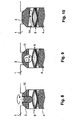
- the clamping element also be arranged in the respective on the insert element. In the FIGS. 5 to 7 different possible embodiments of such clamping elements are shown.
- the possibility is provided in the wedge, that is, in a through hole with thread in the wedge, screws or, as shown here, engage threaded bolt 12, via which targeted again a contact between the bottom of the wedge and the top of the insert element 6 can be made respectively , the tension of the insert element can be increased again and built up.
- the clamping element resp. in this case, the threaded bolt 12 thus serves to lower the distance between the wedge 3 and the upper leaf spring 7 again and accordingly restore the voltage and / or increase.
- FIG. 6 An alternative embodiment is in FIG. 6 shown.
- the clamping element is designed as an eccentric 13, which also makes it possible to reduce the distance between the lower level of the wedge and the upper surface element 7.
- Such an eccentric may, for example, be accessible laterally from the groove.
- FIG. 7 A third embodiment is in FIG. 7 shown.
- the underside of the wedge 3 is either perpendicular to the direction of the groove as in FIG. 7 represented or inclined parallel to the direction of the groove configured, and there is provided an additional clamping wedge 14, which in turn allows to reduce the distance between the underside of the wedge and the upper leaf spring 7.
- clamping element 12, 13, 14 according to the FIGS. 5 to 7 can also be used in combination, it is, for example, possible to provide at the terminal end in the direction of extension, for example, in each case a clamping wedge, since you can access better at these locations under certain circumstances.
- a plurality of threaded bolts 12 arranged in one or more rows can be arranged over the course of the groove, via which, optionally also in different masses at different points along the groove, the tension of the insert element can be readjusted.
- the voltage over the course of the groove can be kept substantially constant by using a torque wrench on the various threaded bolts an equal force is set.
- this insert element is not formed by one or more leaf springs but by a plurality of disc springs.
- the insert element 6 according to the description of Fig. 8-10 is analogous to the insert element according to the description of Fig. 1-7 used.
- each plate spring pair is shown in sectional view.
- Each plate spring pair in turn - as the insert element according to Fig. 1-7 - Two surface elements, wherein one plate spring, an upper surface element 7 and the other plate spring forms a lower surface element 8.
- the two plate springs of each disc spring pair are bent or biased in the opposite direction.
- the disc springs of each disc spring pair are glued to each other at the adjacent surfaces via a primer layer 9 so that the disc spring pair is substantially flat and thus the two disc springs are biased.
- This adhesion promoter layer is a layer of an adhesive which substantially loses its adhesive effect when it exceeds a certain temperature.
- This adhesive may, for example, be a resin or a similar polymeric component whose melting point resp. Glass transition point is at a temperature as it can be set briefly during assembly.
- the two disc springs 7, 8 of each pair of disc springs via other means with each other, so that these means 6 can be selectively released after inserting the insert element.
- a connection which is formed by mechanical vibrations, shockwaves, electromagnetic waves (for example microwaves, ultraviolet, visible or IR radiation) or by a chemical reaction (for example addition of water, solvent or acid) in the holding effect can be resolved. It can therefore not only be a material connection with the help of a primer layer, but it is also possible to provide appropriate screws, rivets, bolts, etc., which solve under the above effects, respectively. dissolve.
- each clamping element 12-14 cooperates with a pair of disc springs to adjust the tension of the disc spring pair, in particular to create or increase the voltage again.
Landscapes
- Engineering & Computer Science (AREA)
- Power Engineering (AREA)
- Manufacturing & Machinery (AREA)
- Insulation, Fastening Of Motor, Generator Windings (AREA)
Claims (22)
- Procédé pour fixer des barres conductrices (4) dans une encoche (2) dans un stator (1) ou un rotor d'une machine électrique ou d'un générateur, selon lequel une ou plusieurs barres conductrices (4) sont insérées dans l'encoche (2), puis au moins un élément d'insertion précontraint (6) est introduit dans l'encoche (2), l'élément d'insertion (6) comportant un élément plan supérieur (7) et un élément plan inférieur (8),
et l'élément plan supérieur (7) ainsi que l'élément plan inférieur (8), à l'état précontraint de l'élément d'insertion (6), étant réalisés respectivement sous forme d'éléments plans formant ressort fléchis l'un par rapport à l'autre dans des directions radiales opposées, lesquels éléments formant ressort étant maintenus ensemble au moyen d'une couche amovible d'agent d'adhérence (9),
l'encoche (2) étant fermée par des cales (3) disposées dans la région de l'ouverture de l'encoche,
et ensuite l'élément d'insertion (6) est relâché de telle sorte que les deux éléments plans (7, 8) fléchissent à l'écart l'un de l'autre dans des directions radiales opposées et une contrainte agissant à l'encontre des barres conductrices (4) peut ainsi être établie, de sorte que les barres conductrices (4) soient pressées dans l'encoche (2) par la cale (3), par l'intermédiaire de l'élément d'insertion (6) sans contrainte. - Procédé selon la revendication 1, caractérisé en ce qu'ensuite, lors d'une étape supplémentaire, on fait glisser et/ou tourner un élément de serrage (12, 13, 14) dans ou sur la cale (3) et/ou dans ou sur l'élément d'insertion (6) de telle sorte qu'un espacement (11) éventuellement présent entre la cale (3) et l'élément d'insertion (6) soit enjambé par cet élément de serrage et/ou que la contrainte de l'élément d'insertion (6) soit accrue.
- Procédé selon la revendication 2, caractérisé en ce que l'élément de serrage (12-14) consiste en un ou plusieurs goujons filetés (12) ou vis encastrés, essentiellement dans la direction de l'encoche, dans un ou plusieurs alésages filetés dans la cale (3), lesquels goujons filetés ou vis sont vissés en direction du fond de l'encoche.
- Procédé selon l'une quelconque des revendications précédentes, caractérisé en ce que l'élément de serrage (12, 13, 14) consiste en un ou plusieurs excentriques (13), que l'on fait tourner, disposés dans ou sur la cale (3).
- Procédé selon l'une quelconque des revendications précédentes, caractérisé en ce que la cale (3) présente sur sa face inférieure tournée vers le fond de l'encoche, au moins par sections, une surface inférieure inclinée, et en ce que l'élément de serrage (12-14) est une cale de serrage (14) réalisée également avec une surface supérieure inclinée en sens inverse et tournée vers la surface inclinée de la cale (3), laquelle cale de serrage est insérée, et/ou en ce que l'élément d'insertion (6) présente sur sa face supérieure opposée au fond de l'encoche, au moins par sections, une surface supérieure inclinée, et en ce que l'élément de serrage (12-14) est une cale de serrage (14) réalisée également avec une surface inférieure inclinée en sens inverse et
tournée vers la surface incliné de l'élément d'insertion (6), laquelle cale de serrage est insérée. - Procédé selon l'une quelconque des revendications précédentes, caractérisé en ce que l'élément d'insertion (6) s'étend dans la direction d'étendue de l'encoche (2).
- Procédé selon l'une quelconque des revendications précédentes, caractérisé en ce que l'élément d'insertion (6) est un élément comportant un élément plan supérieur (7) et un élément plan inférieur (8), au moins l'un de ces éléments plans (7, 8) étant réalisé sous forme de ressort à lame, à une seule ou à plusieurs ondulations, parallèlement ou perpendiculairement à la direction d'étendue de l'encoche (2), et ce ressort à lame étant réalisé de manière essentiellement plane à l'état précontraint, les deux éléments plans (7, 8) étant de préférence réalisés sous forme de ressorts à lame ondulés dans des directions opposées.
- Procédé selon l'une quelconque des revendications 1 à 6, caractérisé en ce que l'élément d'insertion (6) comprend un ou plusieurs éléments parmi lesquels chacun comprend un élément plan supérieur (7) et un élément plan inférieur (8), au moins l'un de ces éléments plans (7, 8) étant réalisé sous forme de ressort Belleville et ce ressort Belleville étant réalisé de manière essentiellement plane à l'état précontraint, les deux éléments plans (7, 8) étant de préférence réalisés sous forme de ressorts Belleville.
- Procédé selon la revendication 8, caractérisé en ce que les multiples éléments sont disposés les uns derrière les autres dans la direction d'étendue de l'encoche (2).
- Procédé selon l'une quelconque des revendications 7 à 9, caractérisé en ce que les deux éléments plans (7, 8) sont maintenus ensemble, à l'état précontraint, au moyen d'une couche d'agent d'adhérence amovible sous au moins une influencé, en particulier de préférence sous l'influence de la chaleur, d'une/de vis, d'un/de rivet(s), d'une/d'agrafe(s) et/ou d'une combinaison de ceux-ci.
- Procédé selon l'une quelconque des revendications précédentes, caractérisé en ce que l'étape supplémentaire n'est effectuée que si la contrainte entre les barres conductrices (4) et la cale (3), assurée par l'élément d'insertion (6), a diminué du fait de l'utilisation et/ou d'un traitement ultérieur du stator ou du rotor.
- Procédé selon l'une quelconque des revendications précédentes, caractérisé en ce que la contrainte de l'élément d'insertion (6) peut être relâchée sous l'influence de la chaleur, de vibrations mécaniques, sous l'influence d'ondes de choc et/ou par une réaction chimique.
- Élément d'insertion (6) pour fixer des barres conductrices (4) dans une encoche (2) dans un stator ou un rotor d'une machine électrique ou d'un générateur, caractérisé en ce que l'élément d'insertion (6) comporte un élément plan supérieur (7) et un élément plan inférieur (8),
l'élément plan supérieur (7) ainsi que l'élément plan inférieur (8), à l'état précontraint de l'élément d'insertion (6), étant réalisés respectivement sous forme d'élémènts plans formant ressort fléchis l'un par rapport à l'autre dans des directions radiales opposées, lesquels éléments formant ressort étant maintenus ensemble au moyen d'une couche amovible, d'agent d'adhérence (9),
et l'élément d'insertion (6) étant relâché dans un état introduit dans l'encoche (2) de telle sorte que les deux éléments plans (7, 8) fléchissent à l'écart l'un de l'autre dans des directions radiales opposées et qu'une contrainte agissant à l'encontre des barres conductrices (4) puisse ainsi être établie, de sorte qu'un espace libre (5) éventuellement présent entre les barres conductrices (4) et la cale (3) puisse être enjambé au moins partiellement par l'élément d'insertion relâché (6) et que les barres conductrices (4) puissent être fixées dans l'encoche (2) au moyen de l'élément d'insertion (6) sans contrainte. - Élément d'insertion (6) selon la revendication 13, caractérisé en ce qu'au moins l'un des éléments plans formant ressort (7, 8) est réalisé sous forme de ressort Belleville.
- Élément d'insertion (6) selon la revendication 13, caractérisé en ce qu'au moins l'un des éléments plans formant ressort (7, 8) est réalisé sous forme de ressort à lame.
- Élément d'insertion (6) selon la revendication 15, caractérisé en ce qu'au moins l'un des éléments plans formant ressort (7, 8) est réalisé sous la forme d'un ressort à lame ondulé.
- Élément d'insertion (6) selon l'une quelconque des revendications 13 à 16, caractérisé en ce que la couche d'agent d'adhérence comporte un adhésif qui perd son adhésivité lorsqu'une température déterminée est dépassée.
- Stator ou rotor, dans lequel une ou plusieurs barres conductrices (4) sont insérées dans une encoche (2), et comprenant une cale (3) et un élément d'insertion (6) selon l'une quelconque des revendications 13 à 17.
- Stator ou rotor selon la revendication 18, caractérisé en ce qu'un élément de serrage (12, 13, 14) est disposé de manière à pouvoir glisser et/ou tourner dans la cale (3) ou sur la cale (3), respectivement dans l'élément d'insertion (6) ou sur l'élément d'insertion (6), de telle sorte que la contrainte de l'élément d'insertion (6) puisse être accrue.
- Stator ou rotor selon la revendication 19, caractérisé en ce que l'élément de serrage (12, 13, 14) consiste en un ou plusieurs goujons filetés (12) ou vis encastrés, essentiellement dans la direction de l'encoche, dans un ou plusieurs alésages filetés dans la cale (3), lesquels goujons filetés ou vis sont vissés en direction du fond de l'encoche.
- Stator ou rotor selon la revendication 19, caractérisé en ce que l'élément de serrage (12, 13, 14) consiste en un ou plusieurs excentriques (13), que l'on peut faire tourner, disposés dans ou sur la cale (3).
- Stator ou rotor selon la revendication 19, caractérisé en ce que la cale (3) présente sur sa face inférieure tournée vers le fond de l'encoche, au moins par sections, une surface inférieure inclinée, et en ce que l'élément de serrage (12-14) est une cale de serrage (14) réalisée également avec une surface supérieure inclinée en sens inverse et tournée vers la surface inclinée de la cale (3), laquelle cale de serrage peut être insérée.
Applications Claiming Priority (2)
| Application Number | Priority Date | Filing Date | Title |
|---|---|---|---|
| PCT/CH2007/000256 WO2008141467A1 (fr) | 2007-05-18 | 2007-05-18 | Procédé de blocage de barres d'enroulement dans des encoches de machines électriques ou de générateurs |
| PCT/EP2008/056053 WO2008142024A1 (fr) | 2007-05-18 | 2008-05-16 | Procédé pour bloquer des barres d'enroulement dans des encoches de machines électriques ou de générateurs |
Publications (2)
| Publication Number | Publication Date |
|---|---|
| EP2149191A1 EP2149191A1 (fr) | 2010-02-03 |
| EP2149191B1 true EP2149191B1 (fr) | 2014-01-08 |
Family
ID=39027277
Family Applications (1)
| Application Number | Title | Priority Date | Filing Date |
|---|---|---|---|
| EP08759690.4A Active EP2149191B1 (fr) | 2007-05-18 | 2008-05-16 | Procédé pour bloquer des barres d'enroulement dans des encoches de machines électriques ou de générateurs |
Country Status (2)
| Country | Link |
|---|---|
| EP (1) | EP2149191B1 (fr) |
| WO (2) | WO2008141467A1 (fr) |
Families Citing this family (3)
| Publication number | Priority date | Publication date | Assignee | Title |
|---|---|---|---|---|
| PL2187504T3 (pl) | 2008-11-18 | 2019-04-30 | Abb Schweiz Ag | Układ do zamykania rowków |
| EP2662956A1 (fr) * | 2012-05-09 | 2013-11-13 | ABB Research Ltd. | Agencement de fermeture à encoche et procédé de fixation de tiges d'enroulement dans des encoches de machines électriques |
| EP2894769A1 (fr) * | 2014-01-10 | 2015-07-15 | Siemens Aktiengesellschaft | Calage rapide de stator |
Family Cites Families (7)
| Publication number | Priority date | Publication date | Assignee | Title |
|---|---|---|---|---|
| US3243622A (en) * | 1963-08-15 | 1966-03-29 | Gen Electric | Retainer for conductors in slots |
| GB1044574A (en) * | 1964-04-17 | 1966-10-05 | Lancashire Dynamo And Crypto L | Improvements in or relating to rotary electric machines |
| JPS6091835A (ja) * | 1983-10-21 | 1985-05-23 | Toshiba Corp | 回転電機 |
| FR2708803B1 (fr) * | 1993-07-30 | 1995-10-20 | Jeumont Ind | Machine tournante chemisée. |
| JPH08116638A (ja) * | 1994-10-18 | 1996-05-07 | Toshiba Corp | 回転電機の円筒形回転子 |
| DE10157582A1 (de) * | 2001-11-23 | 2003-06-05 | Alstom Switzerland Ltd | Dynamoelektrische Maschine mit verkeilten Wicklungsstäben |
| DE10244202A1 (de) * | 2002-09-23 | 2004-03-25 | Alstom (Switzerland) Ltd. | Elektrische Maschine mit einem Stator mit gekühlten Wicklungsstäben |
-
2007
- 2007-05-18 WO PCT/CH2007/000256 patent/WO2008141467A1/fr active Application Filing
-
2008
- 2008-05-16 WO PCT/EP2008/056053 patent/WO2008142024A1/fr active Application Filing
- 2008-05-16 EP EP08759690.4A patent/EP2149191B1/fr active Active
Also Published As
| Publication number | Publication date |
|---|---|
| EP2149191A1 (fr) | 2010-02-03 |
| WO2008141467A1 (fr) | 2008-11-27 |
| WO2008142024A1 (fr) | 2008-11-27 |
Similar Documents
| Publication | Publication Date | Title |
|---|---|---|
| EP2666197B1 (fr) | Batterie avec plusieurs de cellules de batteries | |
| EP2619823A1 (fr) | Système de cadre pour éléments de batterie et module de batterie | |
| WO2011110693A2 (fr) | Pion, cadre et ensemble pour la fixation de modules photovoltaïques ou collecteurs et procédé de fixation de cadres | |
| WO2009083450A2 (fr) | Procédé de montage pour encastrer un aimant permanent dans un élément de retenue | |
| DE202008011312U1 (de) | Verriegelungssystem zum Verriegeln von flächigen Solarmodulen | |
| EP1490554A1 (fr) | Dispositif d'ancrage pour un element de traction protege contre la corrosion, notamment un cable incline de pont haubane | |
| WO2019242925A1 (fr) | Système de support pour l'agencement d'une unité photovoltaïque présentant au moins un module photovoltaïque | |
| EP0952655B1 (fr) | Machine électrique avec rotor muni de barres d'amortisseur | |
| EP2208280B1 (fr) | Procédé pour fixer un ensemble de segments annulaires à paroi externe cylindrique dans un boîtier annulaire | |
| EP2149191B1 (fr) | Procédé pour bloquer des barres d'enroulement dans des encoches de machines électriques ou de générateurs | |
| EP2011949B1 (fr) | Joint d'angle pour cadre de porte et de fenêtre | |
| WO1992010021A1 (fr) | Noyau polaire | |
| EP2252807B1 (fr) | Terminaison pour un câble plat, câble plat avec terminaison, et procédé de fabrication d'un câble plat comportant une terminaison | |
| EP0293614B1 (fr) | Boîte d'installation électrique dans des parois creuses, notamment pour interrupteurs, prises de courant et choses similaires | |
| DE202010012937U1 (de) | Befestigungssystem | |
| DE102013012085A1 (de) | Presse zur Herstellung eines Presslings aus pulverförmigem Material | |
| WO2014108276A2 (fr) | Système pour fermer des rainures | |
| EP1699986B1 (fr) | Construction de parois en bois, du type a madriers en blocs | |
| WO1998006912A1 (fr) | Element de type plaque portante en bois pour constructions de planchers ou de ponts et utilisation d'une vis pour assembler des planches pour former un element de type plaque | |
| DE102018112634A1 (de) | Fugenprofil | |
| EP1551090B1 (fr) | Elément de machine portant un bobinage électrique | |
| EP1980676A2 (fr) | Composant en bois doté d'un élément de liaison ou de protection destiné à être encastré dans le béton ou la terre ou relié à d'autres composants | |
| CH620060A5 (en) | Device for fixing slot wedges for the attachment of electric windings in the longitudinal grooves of the magnetic core of an electric machine | |
| AT525718A1 (de) | Rotor | |
| DE1638274A1 (de) | Anordnung zur Befestigung der Staenderstaebe elektrischer Maschinen in den Nuten des Staenderblechpakets |
Legal Events
| Date | Code | Title | Description |
|---|---|---|---|
| PUAI | Public reference made under article 153(3) epc to a published international application that has entered the european phase |
Free format text: ORIGINAL CODE: 0009012 |
|
| 17P | Request for examination filed |
Effective date: 20091103 |
|
| AK | Designated contracting states |
Kind code of ref document: A1 Designated state(s): AT BE BG CH CY CZ DE DK EE ES FI FR GB GR HR HU IE IS IT LI LT LU LV MC MT NL NO PL PT RO SE SI SK TR |
|
| AX | Request for extension of the european patent |
Extension state: AL BA MK RS |
|
| RIN1 | Information on inventor provided before grant (corrected) |
Inventor name: SCHAAL, STEPHANE Inventor name: PIUR, ARMIN Inventor name: STOLL, DIETER |
|
| DAX | Request for extension of the european patent (deleted) | ||
| 17Q | First examination report despatched |
Effective date: 20120302 |
|
| REG | Reference to a national code |
Ref country code: DE Ref legal event code: R079 Ref document number: 502008010329 Country of ref document: DE Free format text: PREVIOUS MAIN CLASS: H02K0003487000 Ipc: H02K0015000000 |
|
| RIC1 | Information provided on ipc code assigned before grant |
Ipc: H02K 3/487 20060101ALI20121018BHEP Ipc: H02K 15/00 20060101AFI20121018BHEP |
|
| GRAP | Despatch of communication of intention to grant a patent |
Free format text: ORIGINAL CODE: EPIDOSNIGR1 |
|
| GRAS | Grant fee paid |
Free format text: ORIGINAL CODE: EPIDOSNIGR3 |
|
| GRAP | Despatch of communication of intention to grant a patent |
Free format text: ORIGINAL CODE: EPIDOSNIGR1 |
|
| GRAA | (expected) grant |
Free format text: ORIGINAL CODE: 0009210 |
|
| INTG | Intention to grant announced |
Effective date: 20130612 |
|
| AK | Designated contracting states |
Kind code of ref document: B1 Designated state(s): AT BE BG CH CY CZ DE DK EE ES FI FR GB GR HR HU IE IS IT LI LT LU LV MC MT NL NO PL PT RO SE SI SK TR |
|
| REG | Reference to a national code |
Ref country code: GB Ref legal event code: FG4D Free format text: NOT ENGLISH |
|
| REG | Reference to a national code |
Ref country code: CH Ref legal event code: EP |
|
| REG | Reference to a national code |
Ref country code: IE Ref legal event code: FG4D Free format text: LANGUAGE OF EP DOCUMENT: GERMAN |
|
| REG | Reference to a national code |
Ref country code: AT Ref legal event code: REF Ref document number: 622727 Country of ref document: AT Kind code of ref document: T Effective date: 20130815 |
|
| APBM | Appeal reference recorded |
Free format text: ORIGINAL CODE: EPIDOSNREFNO |
|
| APBW | Interlocutory revision of appeal recorded |
Free format text: ORIGINAL CODE: EPIDOSNIRAPO |
|
| REG | Reference to a national code |
Ref country code: DE Ref legal event code: R096 Ref document number: 502008010329 Country of ref document: DE Effective date: 20130912 |
|
| PUAC | Information related to the publication of a b1 document modified or deleted |
Free format text: ORIGINAL CODE: 0009299EPPU |
|
| REG | Reference to a national code |
Ref country code: CH Ref legal event code: NV Representative=s name: ABB SCHWEIZ AG INTELLECTUAL PROPERTY (CH-LC/IP, CH |
|
| GRAJ | Information related to disapproval of communication of intention to grant by the applicant or resumption of examination proceedings by the epo deleted |
Free format text: ORIGINAL CODE: EPIDOSDIGR1 |
|
| GRAS | Grant fee paid |
Free format text: ORIGINAL CODE: EPIDOSNIGR3 |
|
| GRAP | Despatch of communication of intention to grant a patent |
Free format text: ORIGINAL CODE: EPIDOSNIGR1 |
|
| REG | Reference to a national code |
Ref country code: CH Ref legal event code: PK Free format text: BERICHTIGUNG. |
|
| B1DE | Publication of patent cancelled |
Effective date: 20131011 |
|
| DB1 | Publication of patent cancelled | ||
| REG | Reference to a national code |
Ref country code: NL Ref legal event code: GRER Effective date: 20131113 |
|
| INTG | Intention to grant announced |
Effective date: 20131028 |
|
| GRAA | (expected) grant |
Free format text: ORIGINAL CODE: 0009210 |
|
| AK | Designated contracting states |
Kind code of ref document: B1 Designated state(s): AT BE BG CH CY CZ DE DK EE ES FI FR GB GR HR HU IE IS IT LI LT LU LV MC MT NL NO PL PT RO SE SI SK TR |
|
| REG | Reference to a national code |
Ref country code: GB Ref legal event code: FG4D Free format text: NOT ENGLISH |
|
| REG | Reference to a national code |
Ref country code: CH Ref legal event code: PK Free format text: DIE ERTEILUNG VOM 17.07.2013 WURDE VOM EPA WIDERRUFEN Ref country code: CH Ref legal event code: NV Representative=s name: ABB SCHWEIZ AG INTELLECTUAL PROPERTY (CH-LC/IP, CH Ref country code: CH Ref legal event code: EP |
|
| REG | Reference to a national code |
Ref country code: DE Ref legal event code: R107 Ref document number: 502008010329 Country of ref document: DE Effective date: 20140123 |
|
| REG | Reference to a national code |
Ref country code: IE Ref legal event code: FG4D Free format text: LANGUAGE OF EP DOCUMENT: GERMAN |
|
| PG25 | Lapsed in a contracting state [announced via postgrant information from national office to epo] |
Ref country code: SE Free format text: LAPSE BECAUSE OF FAILURE TO SUBMIT A TRANSLATION OF THE DESCRIPTION OR TO PAY THE FEE WITHIN THE PRESCRIBED TIME-LIMIT Effective date: 20130717 Ref country code: AT Free format text: THE PATENT HAS BEEN ANNULLED BY A DECISION OF A NATIONAL AUTHORITY Effective date: 20130717 Ref country code: CY Free format text: LAPSE BECAUSE OF FAILURE TO SUBMIT A TRANSLATION OF THE DESCRIPTION OR TO PAY THE FEE WITHIN THE PRESCRIBED TIME-LIMIT Effective date: 20130821 Ref country code: IS Free format text: LAPSE BECAUSE OF FAILURE TO SUBMIT A TRANSLATION OF THE DESCRIPTION OR TO PAY THE FEE WITHIN THE PRESCRIBED TIME-LIMIT Effective date: 20131117 Ref country code: NO Free format text: LAPSE BECAUSE OF FAILURE TO SUBMIT A TRANSLATION OF THE DESCRIPTION OR TO PAY THE FEE WITHIN THE PRESCRIBED TIME-LIMIT Effective date: 20131017 Ref country code: PT Free format text: LAPSE BECAUSE OF FAILURE TO SUBMIT A TRANSLATION OF THE DESCRIPTION OR TO PAY THE FEE WITHIN THE PRESCRIBED TIME-LIMIT Effective date: 20131118 |
|
| PG25 | Lapsed in a contracting state [announced via postgrant information from national office to epo] |
Ref country code: FI Free format text: LAPSE BECAUSE OF FAILURE TO SUBMIT A TRANSLATION OF THE DESCRIPTION OR TO PAY THE FEE WITHIN THE PRESCRIBED TIME-LIMIT Effective date: 20130717 Ref country code: LV Free format text: LAPSE BECAUSE OF FAILURE TO SUBMIT A TRANSLATION OF THE DESCRIPTION OR TO PAY THE FEE WITHIN THE PRESCRIBED TIME-LIMIT Effective date: 20130717 Ref country code: ES Free format text: LAPSE BECAUSE OF FAILURE TO SUBMIT A TRANSLATION OF THE DESCRIPTION OR TO PAY THE FEE WITHIN THE PRESCRIBED TIME-LIMIT Effective date: 20131028 Ref country code: GR Free format text: LAPSE BECAUSE OF FAILURE TO SUBMIT A TRANSLATION OF THE DESCRIPTION OR TO PAY THE FEE WITHIN THE PRESCRIBED TIME-LIMIT Effective date: 20131018 |
|
| REG | Reference to a national code |
Ref country code: DE Ref legal event code: R096 Ref document number: 502008010329 Country of ref document: DE Effective date: 20140306 |
|
| PG25 | Lapsed in a contracting state [announced via postgrant information from national office to epo] |
Ref country code: CY Free format text: LAPSE BECAUSE OF FAILURE TO SUBMIT A TRANSLATION OF THE DESCRIPTION OR TO PAY THE FEE WITHIN THE PRESCRIBED TIME-LIMIT Effective date: 20130717 |
|
| PG25 | Lapsed in a contracting state [announced via postgrant information from national office to epo] |
Ref country code: RO Free format text: LAPSE BECAUSE OF FAILURE TO SUBMIT A TRANSLATION OF THE DESCRIPTION OR TO PAY THE FEE WITHIN THE PRESCRIBED TIME-LIMIT Effective date: 20130717 Ref country code: EE Free format text: LAPSE BECAUSE OF FAILURE TO SUBMIT A TRANSLATION OF THE DESCRIPTION OR TO PAY THE FEE WITHIN THE PRESCRIBED TIME-LIMIT Effective date: 20130717 |
|
| REG | Reference to a national code |
Ref country code: NL Ref legal event code: VDEP Effective date: 20140108 |
|
| PG25 | Lapsed in a contracting state [announced via postgrant information from national office to epo] |
Ref country code: IT Free format text: LAPSE BECAUSE OF FAILURE TO SUBMIT A TRANSLATION OF THE DESCRIPTION OR TO PAY THE FEE WITHIN THE PRESCRIBED TIME-LIMIT Effective date: 20130717 |
|
| REG | Reference to a national code |
Ref country code: AT Ref legal event code: REF Ref document number: 670140 Country of ref document: AT Kind code of ref document: T Effective date: 20140615 |
|
| REG | Reference to a national code |
Ref country code: LT Ref legal event code: MG4D |
|
| PG25 | Lapsed in a contracting state [announced via postgrant information from national office to epo] |
Ref country code: LT Free format text: LAPSE BECAUSE OF FAILURE TO SUBMIT A TRANSLATION OF THE DESCRIPTION OR TO PAY THE FEE WITHIN THE PRESCRIBED TIME-LIMIT Effective date: 20140108 Ref country code: NO Free format text: LAPSE BECAUSE OF FAILURE TO SUBMIT A TRANSLATION OF THE DESCRIPTION OR TO PAY THE FEE WITHIN THE PRESCRIBED TIME-LIMIT Effective date: 20140408 |
|
| PG25 | Lapsed in a contracting state [announced via postgrant information from national office to epo] |
Ref country code: NL Free format text: LAPSE BECAUSE OF FAILURE TO SUBMIT A TRANSLATION OF THE DESCRIPTION OR TO PAY THE FEE WITHIN THE PRESCRIBED TIME-LIMIT Effective date: 20140108 Ref country code: FI Free format text: LAPSE BECAUSE OF FAILURE TO SUBMIT A TRANSLATION OF THE DESCRIPTION OR TO PAY THE FEE WITHIN THE PRESCRIBED TIME-LIMIT Effective date: 20140108 Ref country code: ES Free format text: LAPSE BECAUSE OF FAILURE TO SUBMIT A TRANSLATION OF THE DESCRIPTION OR TO PAY THE FEE WITHIN THE PRESCRIBED TIME-LIMIT Effective date: 20140108 Ref country code: PL Free format text: LAPSE BECAUSE OF FAILURE TO SUBMIT A TRANSLATION OF THE DESCRIPTION OR TO PAY THE FEE WITHIN THE PRESCRIBED TIME-LIMIT Effective date: 20140108 |
|
| PG25 | Lapsed in a contracting state [announced via postgrant information from national office to epo] |
Ref country code: LV Free format text: LAPSE BECAUSE OF FAILURE TO SUBMIT A TRANSLATION OF THE DESCRIPTION OR TO PAY THE FEE WITHIN THE PRESCRIBED TIME-LIMIT Effective date: 20140108 Ref country code: HR Free format text: LAPSE BECAUSE OF FAILURE TO SUBMIT A TRANSLATION OF THE DESCRIPTION OR TO PAY THE FEE WITHIN THE PRESCRIBED TIME-LIMIT Effective date: 20140108 |
|
| REG | Reference to a national code |
Ref country code: DE Ref legal event code: R097 Ref document number: 502008010329 Country of ref document: DE |
|
| PG25 | Lapsed in a contracting state [announced via postgrant information from national office to epo] |
Ref country code: EE Free format text: LAPSE BECAUSE OF FAILURE TO SUBMIT A TRANSLATION OF THE DESCRIPTION OR TO PAY THE FEE WITHIN THE PRESCRIBED TIME-LIMIT Effective date: 20140108 Ref country code: DK Free format text: LAPSE BECAUSE OF FAILURE TO SUBMIT A TRANSLATION OF THE DESCRIPTION OR TO PAY THE FEE WITHIN THE PRESCRIBED TIME-LIMIT Effective date: 20140108 Ref country code: CZ Free format text: LAPSE BECAUSE OF FAILURE TO SUBMIT A TRANSLATION OF THE DESCRIPTION OR TO PAY THE FEE WITHIN THE PRESCRIBED TIME-LIMIT Effective date: 20140108 |
|
| PLBE | No opposition filed within time limit |
Free format text: ORIGINAL CODE: 0009261 |
|
| STAA | Information on the status of an ep patent application or granted ep patent |
Free format text: STATUS: NO OPPOSITION FILED WITHIN TIME LIMIT |
|
| PG25 | Lapsed in a contracting state [announced via postgrant information from national office to epo] |
Ref country code: SK Free format text: LAPSE BECAUSE OF FAILURE TO SUBMIT A TRANSLATION OF THE DESCRIPTION OR TO PAY THE FEE WITHIN THE PRESCRIBED TIME-LIMIT Effective date: 20140108 |
|
| 26N | No opposition filed |
Effective date: 20141009 |
|
| PG25 | Lapsed in a contracting state [announced via postgrant information from national office to epo] |
Ref country code: LU Free format text: LAPSE BECAUSE OF FAILURE TO SUBMIT A TRANSLATION OF THE DESCRIPTION OR TO PAY THE FEE WITHIN THE PRESCRIBED TIME-LIMIT Effective date: 20140516 |
|
| REG | Reference to a national code |
Ref country code: DE Ref legal event code: R097 Ref document number: 502008010329 Country of ref document: DE Effective date: 20141009 |
|
| PG25 | Lapsed in a contracting state [announced via postgrant information from national office to epo] |
Ref country code: AT Free format text: THE PATENT HAS BEEN ANNULLED BY A DECISION OF A NATIONAL AUTHORITY Effective date: 20140121 Ref country code: MC Free format text: LAPSE BECAUSE OF FAILURE TO SUBMIT A TRANSLATION OF THE DESCRIPTION OR TO PAY THE FEE WITHIN THE PRESCRIBED TIME-LIMIT Effective date: 20140108 |
|
| REG | Reference to a national code |
Ref country code: IE Ref legal event code: MM4A |
|
| PG25 | Lapsed in a contracting state [announced via postgrant information from national office to epo] |
Ref country code: IE Free format text: LAPSE BECAUSE OF NON-PAYMENT OF DUE FEES Effective date: 20140516 |
|
| PG25 | Lapsed in a contracting state [announced via postgrant information from national office to epo] |
Ref country code: SI Free format text: LAPSE BECAUSE OF FAILURE TO SUBMIT A TRANSLATION OF THE DESCRIPTION OR TO PAY THE FEE WITHIN THE PRESCRIBED TIME-LIMIT Effective date: 20140108 |
|
| PG25 | Lapsed in a contracting state [announced via postgrant information from national office to epo] |
Ref country code: MT Free format text: LAPSE BECAUSE OF FAILURE TO SUBMIT A TRANSLATION OF THE DESCRIPTION OR TO PAY THE FEE WITHIN THE PRESCRIBED TIME-LIMIT Effective date: 20140108 |
|
| REG | Reference to a national code |
Ref country code: FR Ref legal event code: PLFP Year of fee payment: 9 |
|
| PG25 | Lapsed in a contracting state [announced via postgrant information from national office to epo] |
Ref country code: BG Free format text: LAPSE BECAUSE OF FAILURE TO SUBMIT A TRANSLATION OF THE DESCRIPTION OR TO PAY THE FEE WITHIN THE PRESCRIBED TIME-LIMIT Effective date: 20140108 |
|
| PG25 | Lapsed in a contracting state [announced via postgrant information from national office to epo] |
Ref country code: TR Free format text: LAPSE BECAUSE OF FAILURE TO SUBMIT A TRANSLATION OF THE DESCRIPTION OR TO PAY THE FEE WITHIN THE PRESCRIBED TIME-LIMIT Effective date: 20140108 Ref country code: HU Free format text: LAPSE BECAUSE OF FAILURE TO SUBMIT A TRANSLATION OF THE DESCRIPTION OR TO PAY THE FEE WITHIN THE PRESCRIBED TIME-LIMIT; INVALID AB INITIO Effective date: 20080516 Ref country code: BE Free format text: LAPSE BECAUSE OF FAILURE TO SUBMIT A TRANSLATION OF THE DESCRIPTION OR TO PAY THE FEE WITHIN THE PRESCRIBED TIME-LIMIT Effective date: 20140531 |
|
| REG | Reference to a national code |
Ref country code: FR Ref legal event code: PLFP Year of fee payment: 10 |
|
| REG | Reference to a national code |
Ref country code: FR Ref legal event code: PLFP Year of fee payment: 11 |
|
| REG | Reference to a national code |
Ref country code: CH Ref legal event code: PFUS Owner name: ABB SCHWEIZ AG, CH Free format text: FORMER OWNER: ABB RESEARCH LTD., CH |
|
| REG | Reference to a national code |
Ref country code: DE Ref legal event code: R081 Ref document number: 502008010329 Country of ref document: DE Owner name: HITACHI ENERGY SWITZERLAND AG, CH Free format text: FORMER OWNER: ABB RESEARCH LTD., ZUERICH, CH Ref country code: DE Ref legal event code: R082 Ref document number: 502008010329 Country of ref document: DE Representative=s name: DENNEMEYER & ASSOCIATES S.A., DE Ref country code: DE Ref legal event code: R082 Ref document number: 502008010329 Country of ref document: DE Representative=s name: ZIMMERMANN & PARTNER PATENTANWAELTE MBB, DE Ref country code: DE Ref legal event code: R081 Ref document number: 502008010329 Country of ref document: DE Owner name: ABB POWER GRIDS SWITZERLAND AG, CH Free format text: FORMER OWNER: ABB RESEARCH LTD., ZUERICH, CH Ref country code: DE Ref legal event code: R081 Ref document number: 502008010329 Country of ref document: DE Owner name: ABB SCHWEIZ AG, CH Free format text: FORMER OWNER: ABB RESEARCH LTD., ZUERICH, CH |
|
| REG | Reference to a national code |
Ref country code: GB Ref legal event code: 732E Free format text: REGISTERED BETWEEN 20200206 AND 20200212 |
|
| REG | Reference to a national code |
Ref country code: CH Ref legal event code: PUE Owner name: ABB POWER GRIDS SWITZERLAND AG, CH Free format text: FORMER OWNER: ABB SCHWEIZ AG, CH |
|
| REG | Reference to a national code |
Ref country code: AT Ref legal event code: PC Ref document number: 670140 Country of ref document: AT Kind code of ref document: T Owner name: ABB SCHWEIZ AG, CH Effective date: 20200128 |
|
| REG | Reference to a national code |
Ref country code: DE Ref legal event code: R081 Ref document number: 502008010329 Country of ref document: DE Owner name: HITACHI ENERGY SWITZERLAND AG, CH Free format text: FORMER OWNER: ABB SCHWEIZ AG, BADEN, CH Ref country code: DE Ref legal event code: R082 Ref document number: 502008010329 Country of ref document: DE Representative=s name: DENNEMEYER & ASSOCIATES S.A., DE Ref country code: DE Ref legal event code: R081 Ref document number: 502008010329 Country of ref document: DE Owner name: ABB POWER GRIDS SWITZERLAND AG, CH Free format text: FORMER OWNER: ABB SCHWEIZ AG, BADEN, CH Ref country code: DE Ref legal event code: R081 Ref document number: 502008010329 Country of ref document: DE Owner name: HITACHI ENERGY LTD, CH Free format text: FORMER OWNER: ABB SCHWEIZ AG, BADEN, CH |
|
| REG | Reference to a national code |
Ref country code: AT Ref legal event code: PC Ref document number: 670140 Country of ref document: AT Kind code of ref document: T Owner name: ABB POWER GRIDS SWITZERLAND AG, CH Effective date: 20210708 |
|
| REG | Reference to a national code |
Ref country code: GB Ref legal event code: 732E Free format text: REGISTERED BETWEEN 20210826 AND 20210901 |
|
| REG | Reference to a national code |
Ref country code: DE Ref legal event code: R081 Ref document number: 502008010329 Country of ref document: DE Owner name: HITACHI ENERGY SWITZERLAND AG, CH Free format text: FORMER OWNER: ABB POWER GRIDS SWITZERLAND AG, BADEN, CH Ref country code: DE Ref legal event code: R081 Ref document number: 502008010329 Country of ref document: DE Owner name: HITACHI ENERGY LTD, CH Free format text: FORMER OWNER: ABB POWER GRIDS SWITZERLAND AG, BADEN, CH |
|
| REG | Reference to a national code |
Ref country code: AT Ref legal event code: HC Ref document number: 670140 Country of ref document: AT Kind code of ref document: T Owner name: HITACHI ENERGY SWITZERLAND AG, CH Effective date: 20220718 |
|
| P01 | Opt-out of the competence of the unified patent court (upc) registered |
Effective date: 20230527 |
|
| PGFP | Annual fee paid to national office [announced via postgrant information from national office to epo] |
Ref country code: FR Payment date: 20230525 Year of fee payment: 16 Ref country code: DE Payment date: 20230519 Year of fee payment: 16 Ref country code: CH Payment date: 20230605 Year of fee payment: 16 |
|
| PGFP | Annual fee paid to national office [announced via postgrant information from national office to epo] |
Ref country code: AT Payment date: 20230522 Year of fee payment: 16 |
|
| PGFP | Annual fee paid to national office [announced via postgrant information from national office to epo] |
Ref country code: GB Payment date: 20230523 Year of fee payment: 16 |
|
| REG | Reference to a national code |
Ref country code: DE Ref legal event code: R082 Ref document number: 502008010329 Country of ref document: DE Representative=s name: DENNEMEYER & ASSOCIATES S.A., DE Ref country code: DE Ref legal event code: R081 Ref document number: 502008010329 Country of ref document: DE Owner name: HITACHI ENERGY LTD, CH Free format text: FORMER OWNER: HITACHI ENERGY SWITZERLAND AG, BADEN, CH |