EP2148322B2 - Ultraschallwandler - Google Patents
Ultraschallwandler Download PDFInfo
- Publication number
- EP2148322B2 EP2148322B2 EP09008962.4A EP09008962A EP2148322B2 EP 2148322 B2 EP2148322 B2 EP 2148322B2 EP 09008962 A EP09008962 A EP 09008962A EP 2148322 B2 EP2148322 B2 EP 2148322B2
- Authority
- EP
- European Patent Office
- Prior art keywords
- housing
- region
- ultrasonic
- waves
- resonators
- Prior art date
- Legal status (The legal status is an assumption and is not a legal conclusion. Google has not performed a legal analysis and makes no representation as to the accuracy of the status listed.)
- Active
Links
Images

Classifications
-
- G—PHYSICS
- G10—MUSICAL INSTRUMENTS; ACOUSTICS
- G10K—SOUND-PRODUCING DEVICES; METHODS OR DEVICES FOR PROTECTING AGAINST, OR FOR DAMPING, NOISE OR OTHER ACOUSTIC WAVES IN GENERAL; ACOUSTICS NOT OTHERWISE PROVIDED FOR
- G10K9/00—Devices in which sound is produced by vibrating a diaphragm or analogous element, e.g. fog horns, vehicle hooters or buzzers
- G10K9/18—Details, e.g. bulbs, pumps, pistons, switches or casings
- G10K9/22—Mountings; Casings
-
- G—PHYSICS
- G01—MEASURING; TESTING
- G01F—MEASURING VOLUME, VOLUME FLOW, MASS FLOW OR LIQUID LEVEL; METERING BY VOLUME
- G01F1/00—Measuring the volume flow or mass flow of fluid or fluent solid material wherein the fluid passes through a meter in a continuous flow
- G01F1/66—Measuring the volume flow or mass flow of fluid or fluent solid material wherein the fluid passes through a meter in a continuous flow by measuring frequency, phase shift or propagation time of electromagnetic or other waves, e.g. using ultrasonic flowmeters
- G01F1/662—Constructional details
-
- G—PHYSICS
- G10—MUSICAL INSTRUMENTS; ACOUSTICS
- G10K—SOUND-PRODUCING DEVICES; METHODS OR DEVICES FOR PROTECTING AGAINST, OR FOR DAMPING, NOISE OR OTHER ACOUSTIC WAVES IN GENERAL; ACOUSTICS NOT OTHERWISE PROVIDED FOR
- G10K11/00—Methods or devices for transmitting, conducting or directing sound in general; Methods or devices for protecting against, or for damping, noise or other acoustic waves in general
- G10K11/002—Devices for damping, suppressing, obstructing or conducting sound in acoustic devices
Definitions
- the invention relates to an ultrasonic transducer with a housing, an ultrasonic window provided in a first region of the housing for transmitting ultrasonic waves between the interior of the ultrasonic transducer and the exterior of the ultrasonic transducer and a transducer element arranged in the housing adjacent to the ultrasonic window, wherein ultrasonic waves can be transmitted as housing waves between the first region of the housing via at least one intermediate second region of the housing and a third region of the housing opposite the first region of the housing.
- Ultrasonic transducers of the aforementioned type have been known for many years and are used extensively in acoustic flow meters, for example.
- the transducer element of the ultrasonic transducer converts electrical energy into a mechanical deflection, and with suitable excitation also into an oscillation in the ultrasonic range.
- the ultrasonic transducer works as an ultrasonic transmitter and the ultrasonic waves are - partially - transmitted via the ultrasonic window into the medium surrounding the ultrasonic transducer.
- the ultrasonic window is deflected by external pressure fluctuations occurring in the medium and the deflection is converted into a corresponding signal by the transducer element; in this case, the ultrasonic transducer works as an ultrasonic receiver.
- an ultrasonic transducer is used both as an ultrasonic transmitter and as an ultrasonic receiver; in the field of flow measurement, an ultrasonic transducer is often used either as an ultrasonic transmitter or as an ultrasonic receiver.
- the ultrasonic waves transmitted through the ultrasonic window that reach the transducer element or originate from the transducer element are the actual useful signal of interest.
- the ultrasonic waves described at the beginning that are passed on or diverted via the housing are parasitic housing waves. The energy transmitted with these waves is not available for the useful signal, so housing waves are generally undesirable.
- Some measures are concerned with the task of preventing such housing waves from occurring. These include, for example, certain designs of the ultrasound window with regard to particularly good impedance matching to maximize the transmitted energy share or with regard to designing the ultrasound window as a ⁇ /4 layer to reduce reflections. Other measures are concerned with preventing housing waves that have already occurred from being transmitted, for example by means of mismatched acoustic impedance transitions. However, housing waves do not only represent a loss of power for the useful signal, they can also have other adverse effects.
- acoustic flow measurement usually makes use of the effect that in a medium transported in a measuring tube, the speed of propagation of the sound signal is superimposed on the transport speed of the medium.
- the measured speed of propagation of the sound signal relative to the measuring tube is therefore greater than in a stationary medium if the medium is transported in the direction of the sound signal, and the speed of the sound signal relative to the measuring tube is lower than in a stationary medium if the medium is transported in the opposite direction to the emission direction of the sound signal.
- the travel time of the sound signal between the sound transmitter and the sound receiver - both are ultrasonic transducers - depends on the transport speed of the medium relative to the measuring tube and thus relative to the sound transmitter and the sound receiver due to the entrainment effect.
- the object of the present invention is therefore to provide an ultrasonic transducer which implements a further measure for preventing the transmission of housing waves via the housing of the ultrasonic transducer and avoids - at least partially - the disadvantages known from the prior art.
- the ultrasonic transducer according to the invention in which the previously derived and indicated object is achieved, is characterized first and foremost by the features of the characterizing part of patent claim 1.
- a further development according to the invention provides that at least two weakly coupled mechanical resonators are formed in the second region of the housing, which are arranged essentially one behind the other in the direction of propagation of the housing waves.
- the inventive design of the ultrasonic transducer or the second area of the housing of the ultrasonic transducer brings with it various advantages.
- the mechanical resonators make it possible to "catch" the energy transported by the ultrasonic waves locally, namely by exciting the mechanical resonators to oscillate.
- Mechanical resonators can usually be described as spring-mass systems, whereby in real spring-mass systems the property of the spring - namely a deflection-dependent force effect - cannot be realized without making a contribution - albeit a very small one - to the mass of the resonator, just as a mass always influences the spring property of the spring-mass system due to its structural introduction into the resonator; spring and mass are actually not completely separable from one another in terms of construction.
- the housing waves have to pass through all the resonators in order to get from the first area of the housing to the third area of the housing and vice versa.
- the weak coupling of the two resonators means that the resonators represent a greater obstacle to the housing waves than is the case with strongly coupled resonators, even if they otherwise have the same vibration properties.
- strong mechanical coupling the vibration of one resonator is transferred almost immediately to the neighboring resonator, which is not the case with weak mechanical coupling, although there is of course a mechanical interaction between the neighboring resonators.
- the natural frequencies of the resonators are in the frequency range of the housing waves, which ensures that as much of the energy of the housing waves as possible is bound in the vibration of the resonators due to the resonance effect of oscillating systems.
- housing waves can be suppressed in a wide frequency range, which is particularly important when emitting or receiving broadband ultrasonic signals.
- the weakly coupled mechanical resonators provided in the second area of the housing thus act practically as a band stop filter (or several band stop filters) in the transmission path from the first area of the ultrasonic transducer to the third area of the ultrasonic transducer.
- the first region of the housing and/or the third region of the housing is designed such that the resonance frequency of the first region of the housing and/or the third region of the housing - within structurally acceptable limits - is as far away as possible from the natural frequencies of the weakly coupled resonators in the second region of the housing and is thus as far away as possible from the operating frequency of the ultrasonic transducer.
- Ultrasonic transducers are often designed in the form of a sleeve in an axial direction of extension in the second region of the housing, with the ultrasonic window in the first region of the housing closing off this sleeve as an end face towards the medium.
- the sleeve-shaped second region of the housing is then usually cylindrical.
- the third region of the housing which is opposite the first region of the housing, can consist, for example, of a flange-like connecting piece or also only in the open end region of the sleeve.
- the housing waves are transmitted via the housing as a whole, also in the axial direction of extension.
- at least one resonator is designed as a hollow ring or as a step, with an upper flat wall, with a lower flat wall and with an end wall connecting the upper flat wall and the lower flat wall.
- a resonator as a hollow ring or as a step is advantageous because both structures can be manufactured very easily and with great precision, for example by machining in one piece from solid material.
- the hollow rings are aligned essentially in the axial direction of extension of the second region of the housing, with the second region of the housing then having wall cross-sections that run in a meandering manner in the axial direction of extension in the region of the hollow rings.
- the stiffness of the end wall of the hollow ring or the step is greater in the axial extension direction than the stiffness of the first flat wall and/or the stiffness of the second flat wall. This measure ensures that oscillation of the resonators in the axial direction of extension is very easy and can be easily excited. If the resonators - as previously explained - are understood as a spring-mass system, then the end wall is the component of the resonator that contributes the majority of the mass, and the first flat wall and/or the second flat wall essentially implement the spring properties of the spring-mass system.
- the stiffness of the end wall - seen in the axial direction of extension - is at least one order of magnitude or even more than two orders of magnitude greater than the stiffness of the first flat wall and/or the stiffness of the second flat wall.
- the above-described and indicated object is achieved in the ultrasonic transducer described at the outset in that the second region of the housing is designed in the form of a sleeve in an axial direction of extension and at least one mechanical resonator is formed in the second region of the housing in such a way that there is no direct connection between the first region and the third region of the housing to which the resonator is attached, so that the housing waves have to pass through the resonator, the resonator being designed as a hollow ring or as a step, with an upper flat wall, with a lower flat wall and with an end wall connecting the upper flat wall and the lower flat wall, and that the natural frequencies of the at least one resonator are in the frequency range of the housing waves.
- the applicant is aware of ultrasonic transducers in practice that have a mechanical resonator in the second, mediating region of the housing, but these are far more complicated in construction and correspondingly more difficult to manufacture.
- the design of the resonator as a hollow ring or as a step is, however, very simple to manufacture and therefore inexpensive to implement, whereby the spring-mass parameters - resonance frequency, damping and thus quality - of this oscillating system are very easy to adjust.
- the parameters are preferably adjusted by a suitable choice of the thickness of the flat walls - spring constant - and the thickness of the end wall - mass. All preferred designs of the weakly coupled resonators are, if transferable, also preferred designs of the single resonator.
- FIG. 1 to 7 Each of the figures shows an ultrasonic transducer 1 with a housing 2 and an ultrasonic window 4 provided in a first region 3 of the housing 2 for transmitting ultrasonic waves between the interior of the ultrasonic transducer 1 and the exterior of the ultrasonic transducer 1; the ultrasonic waves are not shown as such.
- All of the ultrasonic transducers 1 shown also have a transducer element 5 arranged in the housing 2 adjacent to the ultrasonic window 4, which in the cases shown is a piezo crystal.
- the figures are to be described as schematic in that they only show the elements necessary for understanding the present invention; for example, the electrical wiring required to excite the transducer element 5 and to read out electrical signals from the transducer element 5 has been completely omitted.
- the exact structure of the first area 3 of the housing 2 and the design of the ultrasonic window 4 are also not discussed in detail; both can have a very complicated structure, but this is not of fundamental importance in the present case. It is also not important in the present case whether the housing 2 of the ultrasonic transducer 1 in the first area 3 is designed as a single piece or in multiple pieces; various variants are conceivable and different designs are known from the prior art.
- the primary aim of the ultrasonic transducer 1 shown is to transmit the ultrasonic waves generated by the transducer element 5 from the interior of the housing 2 via the ultrasonic windows 4 into the exterior of the ultrasonic transducer 1. It is of great interest to transmit as large a proportion as possible of the energy used to excite the transducer element 5 in the form of ultrasonic waves into the exterior of the housing 2, since this means that the actual useful signal is at its greatest and a good signal-to-noise ratio is achieved.
- the ultrasonic waves are transmitted and can be transmitted as housing waves G between the first area 3 of the housing 2 via an intermediate second area 6 of the housing 2 and a third area 7 of the housing 2 opposite the first area 3 of the housing 2.
- These housing waves G not only reduce the power available for the actual useful signal of interest, but they can also crosstalk to other components of the measuring setup (not shown in detail here), be transmitted further and superimpose the directly transmitted useful ultrasonic waves elsewhere, which makes evaluation of the useful ultrasonic waves more difficult.
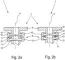
- the third area 7 of the housing 2 is designed as a flange in all illustrated embodiments.
- the possible transmission directions of the housing waves G are indicated, whereby the double arrows make it clear that the housing waves G not only radiate from the first region 3 of the housing 2, but can also be coupled into the third region 7 of the housing 2 and can propagate via the intermediate second region 6 of the housing 2 to the first region 3 of the housing 2.
- the ultrasonic transducers 1 shown are characterized in that two weakly coupled mechanical resonators 8, 9 are formed in the second region 6 of the housing 2, which are arranged one behind the other in the direction of propagation of the housing waves G.
- the mechanical resonators 8, 9 are formed in the housing 2 because this forces the housing waves G to run over and through the resonators 8, 9 in order to get from the first region 3 of the housing 2 to the third region 7 of the housing 2 and vice versa.
- the housing waves G reach the mechanical resonators 8, 9, their energy is - at least partially - accumulated in the resonators 8, 9, since the mechanical resonators 8, 9 are excited to oscillate.
- the behavior of the resonators 8, 9 is particularly advantageous in applications in which the ultrasonic transducer 1 or the transducer element 5 is periodically excited in pulses, in particular at intervals at which the resonator oscillations have decayed again.
- the ultrasonic transducers 1 shown have mechanical resonators 8, 9 whose natural frequencies lie in the frequency range of the housing waves G. This makes it possible to selectively intercept frequency components of the housing waves G or to attenuate their transmission from the first region 3 of the housing 2 to the third region 7 of the housing 2 and vice versa.
- the second, mediating area 6 of the housing 2 is designed in a sleeve-like manner in an axial extension direction A, wherein the housing waves G in the housing 2 of the ultrasonic transducer 1 also essentially spread out in the extension direction A.
- the two resonators 8, 9 shown are designed as a hollow ring, with each resonator 8, 9 having an upper flat wall 10, a lower flat wall 11 and an end wall 12 connecting the upper flat wall 10 and the lower flat wall 11.
- the end wall 12 connects the upper flat wall 10 and the lower flat wall 11 all the way around, so that the housings 2 of the ultrasonic transducers 1 shown are sealed overall when the housings 2 are closed in the third area 7 of the housing with a suitable connection (not shown here).
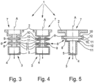
- an ultrasonic transducer 1 which has a resonator 8 designed as a step and a resonator 9 designed as a hollow ring.
- the upper flat wall 10 and the lower flat wall 11 - seen in the axial extension direction - cause an increase in diameter or a reduction in diameter of the sleeve-shaped housing.
- the resonator 9 designed as a hollow ring the upper flat wall 10 and the lower flat wall 11 face each other in the axial extension direction A.
- the resonators 8, 9 designed as hollow rings have in common that they are essentially aligned in the axial direction of extension A of the second region 6 of the housing 2, if it is assumed that the surface normal characterizing the orientation of the hollow rings is perpendicular to the plane in which each hollow ring lies flat. This surface normal is shown in the embodiments coincide with - coaxial with - the center line marked in the figures as the axial extension direction A.
- the second area of the housing 2 has meandering wall cross-sections in the area of the hollow rings in the axial extension direction A.
- the housing waves G could more or less "graze along” resonators designed in this way.
- the housing waves G must practically pass through the mechanical resonators 8, 9.
- the ultrasonic transducers 1 in the exemplary embodiments are designed such that in the axial extension direction A the rigidity of the front wall 12 is greater than the rigidity of the upper flat wall 10 and the rigidity of the lower flat wall 11.
- the rigidities of these elements of the resonators 8, 9 differ by a factor of approximately 300, namely the rigidity of the front wall 12 is greater by a factor of approximately 300 than the rigidity of the upper flat wall 10 and the rigidity of the lower flat wall 11 of each resonator 8, 9.
- a suitable dimensioning of the upper flat wall 10 and the lower flat wall 11 in relation to the connecting end wall 12 is very easy to achieve by using the second order area moments of inertia of the base bodies to calculate the stiffness of these elements with respect to the axial extension direction A.
- this is a circular disk clamped on the circumference and in the case of the connecting end wall 12, for simplicity, a beam.
- FIG. 2a and 2b an ultrasonic transducer 1 with two resonators 8, 9 is shown, whereby the resonators 8, 9 are in the oscillating state.
- the resonators 8, 9 are excited in the first oscillation mode - the upper flat wall 10 and the lower flat wall 11 oscillate in the same direction -, whereas the resonators 8, 9 in Fig. 2b are excited in the second vibration mode, i.e. the upper flat wall 10 and the lower flat wall 11 move in opposite directions to each other.
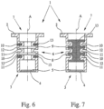
- the ultrasonic transducers 1 according to the Fig. 6 and 7 have damped resonators 8, 9.
- O-rings are provided as damper elements 13 in the outer region of the housing 2 of the ultrasonic transducer 1, whereby these are not arranged between the resonators 8, 9, but rather between a resonator 8, 9 and an adjacent housing part of the resonators 8, 9. This avoids an increase in the coupling between the resonators 8, 9 while at the same time effectively damping the respective resonator oscillations.
- the damper element 13 is formed by a casting compound that fills the resonators 8, 9 or the hollow space of the resonators 8, 9 designed as a hollow ring. This damper element 13 also does not increase the coupling between the resonators 8, 9. Viscoelastic material is suitable as a damper element 13 if it can be ensured that it cannot be displaced from the resonators 8, 9 or the spaces between the resonators. Essentially elastic material is used for the O-rings, namely an elastomer.
Landscapes
- Physics & Mathematics (AREA)
- Engineering & Computer Science (AREA)
- Acoustics & Sound (AREA)
- Multimedia (AREA)
- Electromagnetism (AREA)
- Fluid Mechanics (AREA)
- General Physics & Mathematics (AREA)
- Transducers For Ultrasonic Waves (AREA)
- Measuring Volume Flow (AREA)
- Ultra Sonic Daignosis Equipment (AREA)
Description
- Die Erfindung betrifft einen Ultraschallwandler mit einem Gehäuse, einem in einem ersten Bereich des Gehäuses vorgesehenen Ultraschallfenster zur Übertragung von Ultraschallwellen zwischen dem Innenraum des Ultraschallwandlers und dem Außenraum des Ultraschallwandlers und einem in dem Gehäuse benachbart zum Ultraschallfenster angeordneten Wandlerelement, wobei Ultraschallwellen als Gehäusewellen zwischen dem ersten Bereich des Gehäuses über wenigstens einen vermittelnden zweiten Bereich des Gehäuses und einem dem ersten Bereich des Gehäuses gegenüberliegenden dritten Bereich des Gehäuses übertragbar sind.
- Ultraschallwandler der vorgenannten Art sind seit vielen Jahren bekannt und werden beispielsweise bei akustischen Durchflußmeßgeräten in großem Umfang eingesetzt. Das Wandlerelement des Ultraschallwandlers wandelt elektrische Energie in eine mechanische Auslenkung um, bei geeigneter Anregung also auch in eine Schwingung im Ultraschallbereich. In diesem Fall arbeitet der Ultraschallwandler als Ultraschallsender und die Ultraschallwellen werden - teilweise - über das Ultraschallfenster in das den Ultraschallwandler umgebende Medium übertragen.
- Umgekehrt ist es auch möglich, daß das Ultraschallfenster durch externe - im Medium vorkommende - Druckschwankungen ausgelenkt und die Auslenkung durch das Wandlerelement in ein entsprechendes Signal umgewandelt wird; in diesem Fall arbeitet der Ultraschallwandler als Ultraschallempfänger. In manchen Anwendungen -wie z.B. bei der Füllstandsmessung - wird ein solcher Ultraschallwandler sowohl als Ultraschallsender als auch als Ultraschallempfänger eingesetzt, im Bereich der Durchflußmessung wird ein Ultraschallwandler häufig entweder als Ultraschallsender oder als Ultraschallempfänger eingesetzt.
- In beiden Fällen, also sowohl in dem Fall, in dem der Ultraschallwandler als Sender arbeitet als auch in dem Fall, in dem der Ultraschallwandler als Empfänger arbeitet, handelt es sich bei den über das Ultraschallfenster übertragenen Ultraschallwellen, die das Wandlerelement erreichen bzw. von dem Wandlerelement stammen, um das eigentlich interessierende Nutzsignal. Bei den eingangs beschriebenen Ultraschallwellen, die über das Gehäuse weiter- bzw. abgeleitet werden, handelt es sich um parasitäre Gehäusewellen. Die mit diesen Wellen übertragene Energie steht dem Nutzsignal nicht zur Verfügung, Gehäusewellen sind daher in der Regel unerwünscht.
- Es gibt verschiedene Maßnahmen, um Gehäusewellen zu reduzieren. Einige Maßnahmen befassen sich mit der Aufgabe, derartige Gehäusewellen schon in der Entstehung zu vermeiden. Dazu zählen beispielsweise bestimmte Ausgestaltungen des Ultraschallfensters hinsichtlich einer besonders guten Impedanzanpassung zur Maximierung des transmittierten Energieanteils oder hinsichtlich einer Auslegung des Ultraschallfensters als λ/4-Schicht zur Reduzierung von Reflexionen. Andere Maßnahmen befassen sich damit, bereits entstandene Gehäusewellen an einer Weiterleitung zu hindern, beispielsweise durch fehlangepaßte akustische Impedanzübergänge. Gehäusewellen stellen jedoch nicht nur eine für das Nutzsignal verlorene Verlustleistung dar, sie können darüber hinaus weitere nachteilige Auswirkungen haben.
- Bei der akustischen Durchflußmessung z. B. wird meist der Effekt genutzt, daß in einem in einem Meßrohr transportierten Medium der Ausbreitungsgeschwindigkeit des Schallsignals die Transportgeschwindigkeit des Mediums überlagert ist. Die gemessene Ausbreitungsgeschwindigkeit des Schallsignals gegenüber dem Meßrohr ist also größer als im ruhenden Medium, wenn das Medium in Richtung des Schallsignals transportiert wird, und die Geschwindigkeit des Schallsignals gegenüber dem Meßrohr ist geringer als im ruhenden Medium, wenn das Medium entgegengesetzt zu der Emissionsrichtung des Schallsignals transportiert wird. Die Laufzeit des Schallsignals zwischen dem Schallsender und dem Schallempfänger - beide sind Ultraschallwandler - hängt aufgrund des Mitführeffekts von der Transportgeschwindigkeit des Mediums gegenüber dem Meßrohr und damit gegenüber dem Schallsender und dem Schallempfänger ab.
- Problematisch bei Messungen, die auf emittierten Schall- oder Ultraschallsignalen beruhen, ist, nicht nur im Bereich der Durchflußmessung, daß die von dem Wandlerelement erzeugten Ultraschallschwingungen nicht nur über das Ultraschallfenster des Wandlergehäuses in das umgebende Medium des Ultraschallwandlers übertragen werden, sondern daß die erzeugten Ultraschallschwingungen - teilweise auch - über das Gehäuse als Gehäusewellen auf die gesamte Meßvorrichtung übertragen werden. Dies ist - neben der Verlustleistung - problematisch, weil die durch sogenanntes Übersprechen auf ein Meßgerätegehäuse übertragenen Ultraschallwellen auch zu einer erheblichen empfangsseitigen Störung führen können. Das ist darin begründet, daß empfangsseitig nicht ohne weiteres unterscheidbar ist, ob die empfangenen Ultraschallsignale direkt über das Medium und das Ultraschallfenster empfangen worden sind - Nutzsignal - oder indirekt als Gehäusewellen über die Meßvorrichtung und das gesamte Gehäuse des Ultraschallwandlers, insbesondere also über den dritten Bereich des Gehäuses und den vermittelnden zweiten Bereich des Gehäuses zu dem Wandlerelement gelangt sind.
- Aufgabe der vorliegenden Erfindung ist es daher, einen Ultraschallwandler anzugeben, der eine weitere Maßnahme zur Verhinderung der Übertragung von Gehäusewellen über das Gehäuse des Ultraschallwandlers realisiert und die aus dem Stand der Technik bekannten Nachteile - zumindest teilweise - vermeidet.
- Der erfindungsgemäße Ultraschallwandler, bei dem die zuvor hergeleitete und aufgezeigte Aufgabe gelöst ist, ist zunächst und im wesentlichen durch die Merkmale des Kennzeichnungsteils des Patentanspruchs 1 gekennzeichnet. Eine erfindungsgemäße Weiterbildung sieht vor, daß in dem zweiten Bereich des Gehäuses wenigstens zwei schwach gekoppelte mechanische Resonatoren ausgebildet sind, die in Ausbreitungsrichtung der Gehäusewellen im wesentlichen hintereinander angeordnet sind.
- Die erfindungsgemäße Ausgestaltung des Ultraschallwandlers bzw. des zweiten Bereichs des Gehäuses des Ultraschallwandlers bringt verschiedene Vorteile mit sich. Durch die mechanischen Resonatoren ist es zunächst möglich, die von den Ultraschallwellen transportierte Energie lokal zu "fangen", nämlich durch Anregung der mechanischen Resonatoren zur Schwingung. Mechanische Resonatoren sind üblicherweise als Feder-Masse-Systeme beschreibbar, wobei bei realen Feder-Masse-Systemen die Eigenschaft der Feder - nämlich eine auslenkungsabhängige Kraftwirkung - nicht realisierbar ist, ohne einen - wenn auch sehr kleinen - Beitrag zur Masse des Resonators beizusteuern, genauso wie eine Masse aufgrund ihrer konstruktiven Einbringung in den Resonator auch immer die Federeigenschaft des Feder-Masse-Systems beeinflußt; Feder und Masse sind als konstruktiv tatsächlich nicht vollkommen voneinander trennbar. Durch das serielle Anordnen der zumindest zwei mechanischen Resonatoren in Ausbreitungsrichtung der Gehäusewellen wird erreicht, daß die Gehäusewellen alle Resonatoren durchqueren müssen, um von dem ersten Bereich des Gehäuses zu dem dritten Bereich des Gehäuses zu gelangen und umgekehrt. Durch die schwache Kopplung der beiden Resonatoren wird erreicht, daß die Resonatoren für die Gehäusewellen insgesamt ein größeres Hindernis darstellen, als dies bei stark gekoppelten Resonatoren der Fall ist, selbst wenn diese an sich ansonsten gleiche Schwingungseigenschaften haben. Bei einer starken mechanischen Kopplung überträgt sich die Schwingung eines Resonators praktisch unmittelbar auf den benachbarten Resonator, was bei einer schwachen mechanischen Kopplung nicht der Fall ist, wenngleich auch hier selbstverständlich eine mechanische Wechselwirkung zwischen den benachbarten Resonatoren gegeben ist.
- Bei einer Ausgestaltung der Erfindung ist vorgesehen, daß die Eigenfrequenzen der Resonatoren im Frequenzbereich der Gehäusewellen liegen, wodurch gewährleistet ist, daß aufgrund des Resonanzeffektes schwingfähiger Systeme möglichst viel der Energie der Gehäusewellen in der Schwingung der Resonatoren gebunden wird. In den Resonatoren, die mit verschiedenen Eigenfrequenzen realisiert werden, lassen sich Gehäusewellen in einem breiten Frequenzbereich unterdrücken, was insbesondere bei der Ab- oder Einstrahlung von breitbandigen Ultraschallsignalen von größer Bedeutung ist. Die in dem zweiten Bereich des Gehäuses vorgesehenen schwach gekoppelten mechanischen Resonatoren wirken damit praktisch als eine Bandsperre (oder mehrere Bandsperren) in dem Übertragungsweg von dem ersten Bereich des Ultraschallwandlers zu dem dritten Bereich des Ultraschallwandlers.
- Bei einer weiteren bevorzugten Ausgestaltung ist vorgesehen, daß der erste Bereich des Gehäuses und/oder der dritte Bereich des Gehäuses so ausgelegt ist, daß die Resonanzfrequenz des ersten Bereichs des Gehäuses und/ oder des dritten Bereichs des Gehäuses - im konstruktiv vertretbaren Rahmen - möglichst weit entfernt ist van den Eigenfrequenzen der schwach gekoppelten Resonatoren im zweiten Bereich des Gehäuses und damit möglichst weit bea bstandet sind von der Arbeitsfrequenz des Ultraschallwandlers. Ultraschallwandler sind häufig in dem zweiten Bereich des Gehäuses in einer axialen Erstreckungsrichtung hülsenartig ausgestaltet, wobei das Ultraschallfenster im ersten Bereich des Gehäuses diese Hülse als Stirnfläche zum Medium hin abschlierßt. Der hülsenartig ausgestaltete zweite Bereich des Gehäuses ist dann meist zylinderförmig. Der dritte Bereich des Gehäuses, der dem ersten Bereich des Gehäuses gegenübersteht, kann beispielsweise in einem flanschartigen Anschlußstück bestehen oder auch 20 nur in dem offenen Endbereich der Hülse. Bei einem derart ausgestalteten Ultraschallwandler werden die Gehäusewellen über das Gehäuse insgesamt auch in der axialen Erstreckungsrichtung übertragen. Gemäß der Erfindung ist 25 vorgesehen, daß bei derartig ausgestalteten Ultraschallwandlern wenigstens ein Resonator als Hohlring oder als Stufe ausgestaltet ist, mit einer oberen Flachwand, mit einer unteren Flachwand und mit einer die obere Flachwand und die untere Flachwand verbindenden 30 Stirnwand. Die Ausgestaltung eines Resonators als Hohlring oder als Stufe ist vorteilhaft, weil beide Strukturen fertigungstechnisch sehr einfach und mit großer Präzision herstellbar sind, beispielsweise durch spanabhebendes Drehen einstückig aus Vollmaterial. Größere 35 Hohlringe, deren durch die obere Flachwand, die untere Flachwand und die verbindende Stirnwand begrenzten Hohlraume sehr niedrig sind und sich weit in die Erstreckungsrichtung der Flächwände ausdehnen, sind durch einen mehrteiligen Aufbau gegebenenfalls einfacher her- 40 zustellen. Bei einer besonders bevorzugten Ausgestaltung der Erfindung sind die Hohlringe im wesentlichen in axialer Erstreckungsrichtung des zweiten Bereiches des Gehäuses ausgerichtet, wobei der zweite Bereich des Gehäuses dann im Bereich der Hohlringe in axialer Erstreckungsrichtung insbesondere mäanderförmig verlaufende Wandquerschnitte aufweist. Diese Beschreibung macht deutlich, dar.. eine Gehäusewelle, um von dem ersten Bereich des Gehäuses zu dein dritten Bereich des Gehäuses zu gelangen, zwangsläufig die hintereinander geschalteten Resonatoren durchlaufen muß, die Resonatoren also zwingend nacheinander anregt und - jedenfalls was das Gehäuse des Ultraschallwandlers betrifft - nicht an den Resonatoren vorbeilaufen kann.
- Bei den zuvor beschriebenen Ultraschallwandlem hat es sich als besonders vorteilhaft herausgestellt, wenn in der axialen Erstreckungsrichtung die Steifigkeit der Stirnwand des Hohlrings oder der Stufe größer ist als die Steifigkeit der ersten Flachwand und/oder die Steifigkeit der zweiten Flachwand. Durch diese Maßnahme wird erreicht, daß eine Schwingung der Resonatoren in der axialen Erstreckungsrichtung sehr leicht möglich ist und einfach angeregt werden kann. Wenn die Resonatoren - wie zuvor ausgeführt - als Feder-Masse-System aufgefaßt werden, dann ist die Stirnwand derjenige Bestandteil des Resonators, der den wesentlichen Teil der Masse beisteuert, und die erste Flachwand und/oder die zweite Flachwand setzen im wesentlichen die federnden Eigenschaften des Feder-Masse-Systems um. Um eine schwache Kopplung zwischen den benachbarten Resonatoren zu erreichen, hat es sich als vorteilhaft herausgestellt, wenn die Steifigkeit der Stirnwand - in axialer Erstreckungsrichtung gesehen - um wenigstens eine Größenordnung oder sogar um mehr als zwei Größenordnungen größer ist als die Steifigkeit der ersten Flachwand und/oder die Steifigkeit der zweiten Flachwand.
- Nach der erfindungsgemäßen Dehre der Erfindung ist die weiter oben hergeleitete und aufgezeigte Aufgabe bei dem eingangs beschriebenen Ultraschallwandler dadurch gelöst, daß der zweite Bereich des Gehäuses in einer axialen Erstreckungsrichtung hülsenartig ausgestaltet ist und in dem zweiten Bereich des Gehäuses wenigstens ein mechanischer Resonator ausgebildet ist, derart, dass es keine direkte Verbindung zwischen dem ersten Bereich und dem dritten Bereich des Gehäuses gibt, an die der Resonator angehängt ist, sodass die Gehäusewellen den Resonator durchlaufen müssen, wobei der Resonator als Hohlring oder als Stufe ausgestaltet ist, mit einer oberen Flachwand, mit einer unteren Flachwand und mit einer die obere Flachwand und die untere Flachwand verbindenden Stirnwand und daß die Eigenfrequenzen des wenigstens einen Resonators im Frequenzbereich der Gehäusewellen liegt. Der Anmelderin sind aus der Praxis zwar Ultraschallwandler bekannt, die einen mechanischen Resonator im zweiten, vermittelnden Bereich des Gehäuses aufweisen, edoch sind diese weitaus komplizierter aufgebaut und entsprechend schwieriger zu fertigen. Die Ausgestaltung des Resonators als Hohlring oder als Stufe ist fertigungstechnisch hingegen sehr einfach und damit kostengünstig zu realisieren, wobei die Feder-Masse-Parameter - Resonanzfrequenz, Dämpfung und damit Güte - dieses schwingfähigen Systems sehr einfach einstellbar sind. Die Einstellung der Parameter wird bevorzugt durch geeignete Wahl der Dicke der Flachwände - Federkonstante - und Dicke der Stirnwand - Masse - vorgenommen. Alle bevorzugten Ausgestaltungen der schwach gekoppelten Resonatoren sind, sofern übertragbar, auch bevorzugte Ausgestaltungen des einzigen Resonators.
- Im einzelnen gibt es nun verschiedene Möglichkeiten, den erfindungsgemäßen Ultraschallwandler auszugestalten und weiterzubilden. Dazu wird verwiesen auf die dem Patentanspruch 1 nachgeordneten Patentansprüche und auf die Beschreibung bevorzugter Ausführungsbeispiele in Verbindung mit der Zeichnung. In der Zeichnung zeigen
-
Fig. 1 eine schematische Querschnittsdarstellungeines erfindungsgemäßen Ultraschallwandlers mit zwei mechanischen Resonatoren, -
Fig. 2a, 2b einen Ausschnittaus einer schematischen Querschnittsdarstellung eines erfindungsgemäßen Ultraschallwandlers in unterschiedlichen Anregungsmodi, -
Fig. 3 eine schematische Querschnittsdarstellung eines weiteren Ausführungsbeispiels eines erfindungsgemäßen Ultraschallwandlers, -
Fig. 4 eine schematische Querschnittsdarstellung eines weiteren erfindungsgemäßen Ultraschallwandlers mit konisch zulaufenden Resonatoren, -
Fig. 5 eine schematische Querschnittsdarstellung eines weiteren erfindungsgemäßen Ultraschallwandlers mit einem stufenförmigen Resonator, -
Fig. 6 eine schematische Querschnittsdarstellung eines erfindungsgemäßen Ultraschallwandlers mit O-Ringen als Dämpfungselement und -
Fig. 7 eine schematische Querschnittsdarstellung eines erfindungsgemäßen Ultraschallwandlers mit einer Vergußmasse als Dämpfungselement. - In den
Fig. 1 bis 7 sind jeweils dargestellt Ultraschallwandler 1 mit einem Gehäuse 2 und einem in einem ersten Bereich 3 des Gehäuses 2 vorgesehenen Ultraschallfenster 4 zur Übertragung von Ultraschallwellen zwischen dem Innenraum des Ultraschallwandlers 1 und dem Außenraum des Ultraschallwandlers 1; die Ultraschallwellen sind als solche nicht dargestellt. - Alle dargestellten Ultraschallwandler 1 weisen ferner ein in dem Gehäuse 2 benachbart zum Ultraschallfenster 4 angeordnetes Wandlerelement 5 auf, das in den dargestellten Fällen jeweils ein Piezokristall ist. Die Figuren sind insoweit als schematisch zu bezeichnen, als daß sie nur die zum Verständnis der vorliegenden Erfindung notwendigen Elemente zeigen; so ist beispielsweise auf die Darstellung der zur Anregung des Wandlerelements 5 und zur Auslesung von elektrischen Signalen aus dem Wandlerelement 5 notwendigen elektrischen Verkabelung ganz verzichtet worden. Auch wird nicht im Detail eingegangen auf den genauen Aufbau des ersten Bereichs 3 des Gehäuses 2 und auf die Ausgestaltung des Ultraschallfensters 4, beides kann sehr kompliziert aufgebaut sein, was vorliegend jedoch nicht von grundsätzlicher Bedeutung ist. Es ist vorliegend auch nicht wichtig, ob das Gehäuse 2 des Ultraschallwandlers 1 im ersten Bereich 3 einstückig oder mehrstückig ausgestaltet ist, es sind verschiedene Varianten denkbar und aus dem Stand der Technik sind unterschiedliche Ausgestaltungen bekannt.
- Im Falle eines als Sender arbeitenden Ultraschallwandlers 1 ist es vorrangiges Ziel der dargestellten Ultraschallwandler 1, die durch das Wandlerelement 5 erzeugten Ultraschallwellen von dem Innenraum des Gehäuses 2 über die Ultraschallfenster 4 in den Außenraum des Ultraschallwandlers 1 zu transmittieren. Dabei ist es von großem Interesse, einen möglichst großen Anteil der zur Anregung des Wandlerelements 5 verwendeten Energie in Form von Ultraschallwellen in den Außenraum des Gehäuses 2 zu übertragen, da damit das eigentliche Nutzsignal am größten ist und ein gutes Signal-zu-RauschVerhältnis erzielt wird.
- Es läßt sich jedoch nicht vermeiden, daß ein Teil der Ultraschallwellen als Gehäusewellen G zwischen dem ersten Bereich 3 des Gehäuses 2 über einen vermittelnden zweiten Bereich 6 des Gehäuses 2 und einem dem ersten Bereich 3 des Gehäuses 2 gegenüberliegenden dritten Bereich 7 des Gehäuses 2 übertragen werden und übertragbar sind. Diese Gehäusewellen G reduzieren nicht nur die für das eigentlich interessierende Nutzsignal zur Verfügung stehende Leistung, sondern sie können auch auf weitere Komponenten des hier nicht näher dargestellten Meßaufbau übersprechen, weiter übertragen werden und die direkt übertragenen Nutz-Ultraschallwellen andernorts überlagern, was eine Auswertung der Nutz-Ultraschallwellen erschwert.
- Der dritte Bereich 7 des Gehäuses 2 ist in allen dargestellten Ausführungsbeispielen als Flansch ausgestaltet. In der
Fig. 1 sind die möglichen Übertragungsrichtungen der Gehäusewellen G angedeutet, wobei die Doppelpfeile verdeutlichen, daß die Gehäusewellen G nicht nur ausgehend von dem ersten Bereich 3 des Gehäuses 2 ausstrahlen, sondern auch in den dritten Bereich 7 des Gehäuses 2 eingekoppelt werden können und sich über den vermittelnden zweiten Bereich 6 des Gehäuses 2 zu dem ersten Bereich 3 des Gehäuses 2 fortpflanzen können. - Die dargestellten Ultraschallwandler 1 zeichnen sich dadurch aus, daß in dem zweiten Bereich 6 des Gehäuses 2 zwei schwach gekoppelte mechanische Resonatoren 8, 9 ausgebildet sind, die in Ausbreitungsrichtung der Gehäusewellen G hintereinander angeordnet sind. In den dargestellten Ausführungsbeispielen sind die mechanischen Resonatoren 8, 9 in dem Gehäuse 2 ausgebildet, weil dadurch erzwungen wird, daß die Gehäusewellen G über und durch die Resonatoren 8, 9 verlaufen müssen, um von dem ersten Bereich 3 des Gehäuses 2 in den dritten Bereich 7 des Gehäuses 2 und umgekehrt zu gelangen. Sobald die Gehäusewellen G die mechanischen Resonatoren 8, 9 erreichen, wird ihre Energie - zumindest teilweise - in den Resonatoren 8, 9 akkumuliert, da die mechanischen Resonatoren 8, 9 zu Schwingungen angeregt werden. Damit ist es möglich, die mit den Gehäusewellen G übertragene Energie - zumindest teilweise - zunächst zu lokalisieren. Damit ist das Ziel erreicht, daß die Gehäusewellen G ungehindert von einem Ende des Gehäuses 2 zu dem anderen Ende des Gehäuses 2 des Ultraschallwandlers 1 gelangen können. Die Energie wird zunächst in den Resonatoren 8, 9 "gefangen" und dann - zeitverzögert, über einen längeren Zeitraum - wieder abgegeben; das Signalzu-Rausch-Verhältnis verbessert sich dadurch beträchtlich. Da jeder reale Resonator auch gedämpft ist, wird ein Teil der Energie der Gehäusewellen G in den Resonatoren 8, 9 in Wärme umgesetzt, jedenfalls nicht mehr als Energie in Form von Ultraschallwellen abgegeben.
- Das Verhalten der Resonatoren 8, 9 ist insbesondere bei solchen Anwendungsfällen vorteilhaft, bei denen der Ultraschallwandler 1 bzw. das Wandlerelement 5 periodisch impulsweise angeregt wird, insbesondere in solchen Abständen, in denen die Resonatorschwingungen wieder abgeklungen sind.
- Die in den
Fig. 1 bis 7 dargestellten Ultraschallwandler 1 weisen mechanische Resonatoren 8, 9 auf, deren Eigenfrequenzen im Frequenzbereich der Gehäusewellen G liegen. Dadurch ist es möglich, selektiv Frequenzanteile der Gehäusewellen G abzufangen bzw. deren Übertragung vom ersten Bereich 3 des Gehäuses 2 zum dritten Bereich 7 des Gehäuses 2 und umgekehrt abzuschwächen. - Wie in den
Fig. 1 bis 7 zu erkennen, ist der zweite, vermittelnde Bereich 6 des Gehäuses 2 in einer axialen Erstreckungsrichtung A hülsenartig ausgestaltet, wobei sich in der Erstreckungsrichtung A auch die Gehäusewellen G im Gehäuse 2 des Ultraschallwandlers 1 im wesentlichen ausbreiten. In denFig. 1 bis 4 sowie 6 und 7 sind die beiden jeweils dargestellten Resonatoren 8, 9 als Hohlring ausgestaltet, wobei jeder Resonator 8, 9 eine obere Flachwand 10, eine untere Flachwand 11 und eine die obere Flachwand 10 und die untere Flachwand 11 verbindende Stirnwand 12 aufweist. Die Stirnwand 12 verbindet die obere Flachwand 10 und die untere Flachwand 11 jeweils umlaufend, so daß die Gehäuse 2 der dargestellten Ultraschallwandler 1 insgesamt dicht sind, wenn die Gehäuse 2 in dem dritten Bereich 7 des Gehäuses mit einem geeigneten, hier nicht dargestellten Anschluß verschlossen werden. - In der
Fig. 5 ist ein Ultraschallwandler 1 dargestellt, der einen als Stufe ausgestalteten Resonator 8 und einen als Hohlring ausgestalteten Resonator 9 aufweist. Bei dem als Stufe ausgebildeten Resonator 8 bewirken die obere Flachwand 10 und die untere Flachwand 11 - in axialer Erstreckungsrichtung gesehen -eine Durchmessererweiterung bzw. eine Durchmesserverringerung des hülsenartig ausgestalteten Gehäuses. Demgegenüber stehen sich bei dem als Hohlring ausgestalteten Resonator 9 in axialer Erstreckungsrichtung A die obere Flachwand 10 und die untere Flachwand 11 gegenüber. - In den
Fig. 1 bis 7 haben die als Hohlringe ausgestalteten Resonatoren 8, 9 gemeinsam, daß sie im wesentlichen in axialer Erstreckungsrichtung A des zweiten Bereiches 6 des Gehäuses 2 ausgerichtet sind, wenn davon ausgegangen wird, daß die die Orientierung der Hohlringe kennzeichnende Flächennormale senkrecht auf der Ebene steht, in der jeder Hohlrings jeweils flachseitig liegt. Diese Flächennormale ist in den dargestellten Ausführungsbeispielen deckungsgleich mit - koaxial zu - der in den Figuren als axiale Erstreckungsrichtung A gekennzeichneten Mittellinie. Der zweite Bereich des Gehäuses 2 weist im Bereich der Hohlringe in axialer Erstreckungsrichtung A demzufolge mäanderförmig verlaufende Wandquerschnitte auf. Wichtig ist, daß es keine direkte Verbindung zwischen dem ersten Bereich 3 des Gehäuses 2 und dem dritten Bereich 7 des Gehäuses 2 gibt, an die die Resonatoren 8, 9 quasi nur "angehängt" sind, da in diesen Fällen die Resonatoren nicht effektiv genutzt werden könnten, da die Gehäusewellen G an derart ausgestalteten Resonatoren quasi "entlangstreifen" könnten. In den dargestellten Ausführungsbeispielen müssen die Gehäusewellen G die mechanischen Resonatoren 8, 9 praktisch durchlaufen. - Bei den in den
Fig. 1 bis 7 dargestellten Ausführungsbeispielen handelt es sich um schematische Zeichnungen, die nicht zwingend maßstabsgerecht sind. Insbesondere ist in den Figuren nicht maßstabsgetreu dargestellt, in welchem Verhältnis die Dicke der oberen Flachwand 10 und der unteren Flachwand 11 zu der Dicke der verbindenden Stirnwand 12 jeweils steht. Tatsächlich sind die Ultraschallwandler 1 in den Ausführungsbeispielen so ausgeführt, daß in axialer Erstreckungsrichtung A die Steifigkeit der Stirnwand 12 größer ist als die Steifigkeit der oberen Flachwand 10 und die Steifigkeit der unteren Flachwand 11. In den dargestellten Fällen unterscheiden sich die Steifigkeiten dieser Elemente der Resonatoren 8, 9 in etwa um den Faktor 300, ist nämlich die Steifigkeit der Stirnwand 12 um etwa den Faktor 300 größer als die Steifigkeit der oberen Flachwand 10 und die Steifigkeit der unteren Flachwand 11 eines jeden Resonators 8, 9. Dadurch wird bewirkt, daß die Resonatoren 8, 9 besonders schwingfähig in axialer Erstreckungsrichtung A des Gehäuses 2 und damit in der Laufrichtung der Gehäusewellen G sind. - Eine geeignete Dimensionierung der oberen Flachwand 10 und der unteren Flachwand 11 gegenüber der verbindenden Stirnwand 12 ergibt sich sehr einfach, indem zur Berechnung der Steifigkeiten dieser Elemente hinsichtlich der axialen Erstreckungsrichtung A die Flächenträgheitsmomente zweiter Ordnung der Grundkörper herangezogen werden. Dies ist im Falle der oberen Flachwand 10 und der unteren Flachwand 11 eine am Umfang eingespannte Kreisringscheibe und im Falle der verbindenden Stirnwand 12 vereinfachend ein Balken.
- In den
Fig. 2a und 2b ist jeweils ein Ultraschallwandler 1 mit zwei Resonatoren 8, 9 dargestellt, wobei sich die Resonatoren 8, 9 im schwingenden Zustand befinden. InFig. 2a sind die Resonatoren 8, 9 im ersten Schwingungsmodus angeregt - die obere Flachwand 10 und die untere Flachwand 11 schwingen gleichsinnig -, wohingegen die Resonatoren 8, 9 inFig. 2b im zweiten Schwingungsmodus angeregt sind, sich also jeweils die obere Flachwand 10 und die untere Flachwand 11 gegenläufig zueinander bewegen. - Die Ultraschallwandler 1 gemäß den
Fig. 6 und 7 weisen gedämpfte Resonatoren 8, 9 auf. Im Ausführungsbeispiel gemäßFig. 6 sind im Außenbereich des Gehäuses 2 des Ultraschallwandlers 1 als Dämpferelemente 13 O-Ringe vorgesehen, wobei diese nicht zwischen den Resonatoren 8, 9 angeordnet sind, sondern jeweils zwischen einem Resonator 8, 9 und einem benachbarten Gehäuseteil der Resonatoren 8, 9. Dadurch wird eine Verstärkung der Kopplung zwischen den Resonatoren 8, 9 vermieden bei gleichzeitiger effektiver Dämpfung der jeweiligen Resonatorschwingungen. - In
Fig. 7 wird das Dämpferelement 13 durch eine Vergußmasse gebildet, die die Resonatoren 8, 9 bzw. den Hohlraum der als Hohlring ausgebildeten Resonatoren 8, 9 ausfüllt. Auch durch dieses Dämpferelement 13 wird die Kopplung zwischen den Resonatoren 8, 9 nicht verstärkt. Viskoelastisches Material eignet sich als Dämpferelement 13, wenn sichergestellt werden kann, daß es nicht aus den Resonatoren 8, 9 bzw. den Zwischenräumen zwischen den Resonatoren verdrängt werden kann. Für die O-Ringe wird im Wesentlichen elastisches Material verwendet, nämlich ein Elastomer.
Claims (6)
- Ultraschallwandler mit einem Gehäuse (2), einem in einem ersten Bereich (3) des Gehäuses (2) vorgesehenen Ultraschallfenster (4) zur Übertragung von Ultraschallwellen zwischen dem Innenraum des Ultraschallwandlers und dem Außenraum des Ultraschallwandlers und einem in dem Gehäuse (2) benachbart zum Ultraschallfenster (4) angeordneten Wandlerelement (5), wobei Ultraschallwellen als Gehäusewellen (G) zwischen dem ersten Bereich (3) des Gehäuses (2) über wenigstens einen vermittelnden zweiten Bereich (6) des Gehäuses (2) und einem dem ersten Bereich (3) des Gehäuses (2) gegenüberliegenden dritten Bereich (7) des Gehäuses (2) übertragbar sind,
dadurch gekennzeichnet,daß der zweite Bereich (6) des Gehäuses (2) in einer axialen Erstreckungsrichtung (A) hülsenartig ausgestaltet ist und in dem zweiten Bereich (6) des Gehäuses (2) wenigstens ein mechanischer Resonator (8, 9) ausgebildet ist,derart dass es keine direkte Verbindung zwischen dem ersten Bereich (3) und dem dritten Bereich (7) des Gehäuses (2) gibt, an die der Resonator (8, 9) angehängt ist, sodass die Gehäusewellen (G) den Resonator (8, 9) durchlaufen müssen,wobei der Resonator (8, 9) als Hohlring oder als Stufe ausgestaltet ist, mit einer oberen Flachwand (10), mit einer unteren Flachwand (11) und mit einer die obere Flachwand (10) und die untere Flachwand (11) verbindenden Stirnwand (12) und daß die Eigenfrequenzen des wenigstens einen Resonators (8, 9) im Frequenzbereich der Gehäusewellen (G) liegt. - Ultraschallwandler nach Anspruch 1, dadurch gekennzeichnet, daß in dem zweiten Bereich (6) des Gehäuses (2) wenigstens zwei schwach gekoppelte mechanische Resonatoren (8, 9) ausgebildet sind, die in Ausbreitungsrichtung der Gehäusewellen (G) im wesentlichen hintereinander angeordnet sind.
- Ultraschallwandler nach Anspruch 1 oder 2, dadurch gekennzeichnet, daß die Hohlringe im wesentlichen in axialer Erstreckungsrichtung (A) des zweiten Bereiches (6) des Gehäuses (2) ausgerichtet sind, insbesondere wobei der zweite Bereich (6) des Gehäuses (2) im Bereich der Hohlringe in axialer Erstreckungsrichtung (A) mäanderförmig verlaufende Wandquerschnitte aufweist.
- Ultraschallwandler nach einem der Ansprüche 1 bis 3, dadurch gekennzeichnet, daß in axialer Erstreckungsrichtung (A) die Steifigkeit der Stirnwand (12) größer ist als die Steifigkeit der oberen Flachwand (10) und/oder die Steifigkeit der unteren Flachwand (11), insbesondere um wenigstens eine Größenordnung größer ist, bevorzugt um wenigstens zwei Größenordnungen größer ist.
- Ultraschallwandler nach einem der Ansprüche 1 bis 4, dadurch gekennzeichnet, daß wenigstens ein Resonator (8, 9) gedämpft ist, insbesondere durch wenigstens ein in einem Resonator (8, 9) und/oder zwischen zwei Resonatoren (8, 9) oder benachbart zu einem Resonator (8, 9) angeordnetes Dämpferelement (13).
- Ultraschallwandler nach Anspruch 5, dadurch gekennzeichnet, daß das Dämpferelement (13) wenigstens ein O-Ringe oder eine Vergußmasse ist, insbesondere aus einem elastischen oder viskoelastischen Material.
Applications Claiming Priority (1)
| Application Number | Priority Date | Filing Date | Title |
|---|---|---|---|
| DE102008033098.1A DE102008033098C5 (de) | 2008-07-15 | 2008-07-15 | Ultraschallwandler |
Publications (4)
| Publication Number | Publication Date |
|---|---|
| EP2148322A2 EP2148322A2 (de) | 2010-01-27 |
| EP2148322A3 EP2148322A3 (de) | 2014-05-14 |
| EP2148322B1 EP2148322B1 (de) | 2017-03-01 |
| EP2148322B2 true EP2148322B2 (de) | 2024-12-11 |
Family
ID=41401890
Family Applications (1)
| Application Number | Title | Priority Date | Filing Date |
|---|---|---|---|
| EP09008962.4A Active EP2148322B2 (de) | 2008-07-15 | 2009-07-09 | Ultraschallwandler |
Country Status (6)
| Country | Link |
|---|---|
| US (1) | US7973453B2 (de) |
| EP (1) | EP2148322B2 (de) |
| JP (1) | JP5355268B2 (de) |
| CN (1) | CN101676693B (de) |
| CA (1) | CA2672058C (de) |
| DE (1) | DE102008033098C5 (de) |
Families Citing this family (20)
| Publication number | Priority date | Publication date | Assignee | Title |
|---|---|---|---|---|
| DE102010064117A1 (de) | 2010-12-23 | 2012-06-28 | Endress + Hauser Flowtec Ag | Ultraschallwandler |
| CN102879044A (zh) * | 2011-07-15 | 2013-01-16 | 上海一诺仪表有限公司 | 超声波换能器壳体结构 |
| CN103959018B (zh) * | 2011-09-23 | 2016-08-24 | 卡姆鲁普股份有限公司 | 具有突伸的换能器的流量计 |
| DE102011090082A1 (de) * | 2011-12-29 | 2013-07-04 | Endress + Hauser Flowtec Ag | Ultraschallwandler für ein Durchflussmessgerät |
| EP2762842B1 (de) * | 2013-01-28 | 2024-02-14 | Krohne AG | Ultraschallwandler für ein ultraschalldurchflussmessgerät |
| DE102013020497B4 (de) | 2013-01-28 | 2018-10-11 | Krohne Ag | Baueinheit aus einem Ultraschallwandler und einen Wandlerhalter |
| DE102013211606A1 (de) * | 2013-06-20 | 2014-12-24 | Robert Bosch Gmbh | Umfeldsensiereinrichtung mit Ultraschallwandler, und Kraftfahrzeug mit einer derartigen Umfeldsensiereinrichtung |
| JP6693941B2 (ja) | 2014-07-11 | 2020-05-13 | マイクロテック メディカル テクノロジーズ リミテッド | マルチセル・トランスデューサー |
| DE102014115589A1 (de) | 2014-10-27 | 2016-04-28 | Endress + Hauser Flowtec Ag | Anordnung zum Aussenden und/oder Empfangen eines Ultraschall-Nutzsignals und Ultraschall-Durchflussmessgerät |
| DE102014115592A1 (de) | 2014-10-27 | 2016-04-28 | Endress + Hauser Flowtec Ag | Anordnung zum Aussenden und/oder Empfangen eines Ultraschall-Nutzsignals und Ultraschall-Durchflussmessgerät |
| DE102015103486A1 (de) * | 2015-03-10 | 2016-09-15 | Endress + Hauser Flowtec Ag | Anordnung und Feldgerät der Prozessmesstechnik |
| DE102015106352A1 (de) | 2015-04-24 | 2016-10-27 | Endress + Hauser Flowtec Ag | Anordnung und Ultraschall-Durchflussmessgerät |
| LT3178570T (lt) * | 2015-12-07 | 2019-03-25 | Danfoss A/S | Ultragarsinis keitlys ir ultragarsinio keitlio gamybos būdas |
| EP3273210B1 (de) | 2016-07-18 | 2022-05-18 | VEGA Grieshaber KG | Vibrationsgrenzstandsschalter und verfahren zur herstellung eines vibrationsgrenzstandsschalter |
| DE102017214370A1 (de) * | 2017-08-17 | 2019-02-21 | Landis + Gyr Gmbh | Schallkopf für einen Durchflussmesser mit gestufter Seitenwand |
| DE102018213853A1 (de) * | 2018-08-17 | 2020-02-20 | Zf Friedrichshafen Ag | System zum Messen eines Füllstands |
| CN110801297B (zh) * | 2019-12-05 | 2025-02-14 | 深圳市凡超科技有限公司 | 超声波换能结构及手持式洁牙器 |
| CN114257935A (zh) * | 2020-09-25 | 2022-03-29 | 克洛纳测量技术有限公司 | 超声变换器和其运行方法、超声流量测量仪和其运行方法 |
| EP4170296B1 (de) | 2021-10-22 | 2023-10-11 | Krohne AG | Ultraschallwandler und ultraschalldurchflussmessgerät |
| DE102022114985B3 (de) * | 2022-06-14 | 2023-10-05 | Krohne Ag | Ultraschalldurchflussmessgerät |
Citations (6)
| Publication number | Priority date | Publication date | Assignee | Title |
|---|---|---|---|---|
| DE3314733A1 (de) † | 1982-04-27 | 1983-10-27 | Juval Dr.-Ing. 8000 München Mantel | Abschirmvorrichtung gegen durch schallfrequenzwellen hervorgerufene schwingungen |
| DE3941634A1 (de) † | 1989-12-15 | 1991-06-20 | Siemens Ag | Schallisolierte halterung eines ultraschallwandlers |
| US5275060A (en) † | 1990-06-29 | 1994-01-04 | Panametrics, Inc. | Ultrasonic transducer system with crosstalk isolation |
| EP1340964A1 (de) † | 2002-03-01 | 2003-09-03 | SICK Engineering GmbH | Ultraschallwandleranordnung mit Ultraschallfilter |
| DE10084627B4 (de) † | 1999-05-24 | 2006-09-21 | Joseph Baumoel | Messwertaufnehmer zur akustischen Messung eines Gasstromes und deren Charakteristika |
| US20070115102A1 (en) † | 2005-11-21 | 2007-05-24 | Denso Corporation | Ultrasound sensor |
Family Cites Families (14)
| Publication number | Priority date | Publication date | Assignee | Title |
|---|---|---|---|---|
| JPS5927870U (ja) * | 1982-08-16 | 1984-02-21 | ティーディーケイ株式会社 | 音響変換器 |
| US4770038A (en) * | 1986-02-13 | 1988-09-13 | The United States Of America As Represented By The Administrator Of National Aeronautics And Space Administration | Ultrasonic depth gauge for liquids under high pressure |
| JPH0618245Y2 (ja) * | 1988-05-20 | 1994-05-11 | トキコ株式会社 | 超音波センサ |
| DE59007347D1 (de) * | 1990-05-19 | 1994-11-03 | Flowtec Ag | Messerwertaufnehmer für ein Ultraschall-Volumendurchfluss-Messgerät. |
| JP2653391B2 (ja) * | 1990-05-19 | 1997-09-17 | エンドレス ウント ハウザー フローテック アクチエンゲゼルシャフト | 流量測定装置用超音波送受変換素子 |
| US5515733A (en) * | 1991-03-18 | 1996-05-14 | Panametrics, Inc. | Ultrasonic transducer system with crosstalk isolation |
| US5437194A (en) * | 1991-03-18 | 1995-08-01 | Panametrics, Inc. | Ultrasonic transducer system with temporal crosstalk isolation |
| JP3041242B2 (ja) * | 1996-06-28 | 2000-05-15 | 株式会社アルテクス | 超音波振動用共振器の支持装置 |
| JP3569799B2 (ja) * | 1998-12-17 | 2004-09-29 | 株式会社泉技研 | 超音波流量計 |
| DE19951874C2 (de) * | 1999-10-28 | 2003-05-22 | Krohne Ag Basel | Ultraschall-Durchflußmeßgerät |
| JP3738891B2 (ja) * | 2000-05-23 | 2006-01-25 | 富士電機システムズ株式会社 | 超音波流量計 |
| DE10153297C2 (de) * | 2001-09-14 | 2003-09-25 | Krohne Ag Basel | Meßgerät |
| DE10205545B4 (de) * | 2001-11-28 | 2005-09-15 | Krohne Ag | Durchflußmeßgerät |
| EP1316780B1 (de) * | 2001-11-28 | 2016-12-28 | Krohne AG | Ultraschall-Durchflussmessgerät |
-
2008
- 2008-07-15 DE DE102008033098.1A patent/DE102008033098C5/de active Active
-
2009
- 2009-07-09 EP EP09008962.4A patent/EP2148322B2/de active Active
- 2009-07-14 CA CA2672058A patent/CA2672058C/en active Active
- 2009-07-15 JP JP2009167031A patent/JP5355268B2/ja active Active
- 2009-07-15 US US12/503,356 patent/US7973453B2/en active Active
- 2009-07-15 CN CN2009101733634A patent/CN101676693B/zh active Active
Patent Citations (6)
| Publication number | Priority date | Publication date | Assignee | Title |
|---|---|---|---|---|
| DE3314733A1 (de) † | 1982-04-27 | 1983-10-27 | Juval Dr.-Ing. 8000 München Mantel | Abschirmvorrichtung gegen durch schallfrequenzwellen hervorgerufene schwingungen |
| DE3941634A1 (de) † | 1989-12-15 | 1991-06-20 | Siemens Ag | Schallisolierte halterung eines ultraschallwandlers |
| US5275060A (en) † | 1990-06-29 | 1994-01-04 | Panametrics, Inc. | Ultrasonic transducer system with crosstalk isolation |
| DE10084627B4 (de) † | 1999-05-24 | 2006-09-21 | Joseph Baumoel | Messwertaufnehmer zur akustischen Messung eines Gasstromes und deren Charakteristika |
| EP1340964A1 (de) † | 2002-03-01 | 2003-09-03 | SICK Engineering GmbH | Ultraschallwandleranordnung mit Ultraschallfilter |
| US20070115102A1 (en) † | 2005-11-21 | 2007-05-24 | Denso Corporation | Ultrasound sensor |
Also Published As
| Publication number | Publication date |
|---|---|
| CN101676693A (zh) | 2010-03-24 |
| EP2148322A3 (de) | 2014-05-14 |
| CN101676693B (zh) | 2012-10-03 |
| US7973453B2 (en) | 2011-07-05 |
| DE102008033098B4 (de) | 2010-07-01 |
| JP5355268B2 (ja) | 2013-11-27 |
| DE102008033098C5 (de) | 2016-02-18 |
| JP2010028815A (ja) | 2010-02-04 |
| EP2148322A2 (de) | 2010-01-27 |
| CA2672058C (en) | 2015-09-29 |
| US20100011866A1 (en) | 2010-01-21 |
| EP2148322B1 (de) | 2017-03-01 |
| DE102008033098A1 (de) | 2010-01-21 |
| CA2672058A1 (en) | 2010-01-15 |
Similar Documents
| Publication | Publication Date | Title |
|---|---|---|
| EP2148322B2 (de) | Ultraschallwandler | |
| DE3611669C2 (de) | ||
| EP0644999B1 (de) | Füllstandsmessgerät | |
| EP2559024A2 (de) | Verfahren zum ansteuern eines ultraschallsensors und ultraschallsensor | |
| EP2650656A1 (de) | Coriolis-Massendurchflußmeßgerät | |
| EP3855134B1 (de) | Vorrichtung zur messung der flussgeschwindigkeit eines fluids | |
| DE102019124454A1 (de) | Fluidmesseinrichtung mit einem Fluidgehäuse und Verfahren zur Herstellung eines Fluidgehäuses | |
| EP3521774B1 (de) | Ultraschall-durchflussmessvorrichtung und verfahren zum bestimmen der strömungsgeschwindigkeit | |
| WO1991009465A1 (de) | Oberflächenwellen-reflektorfilter | |
| EP3940346B1 (de) | Durchflussmessgerät und verfahren zur messung des durchflusses eines fluids | |
| DE102006058437A1 (de) | Kraftmessbolzen zur Messung mechanischer Spannungen | |
| DE202020104105U1 (de) | Durchflussmessgerät zur Messung des Durchflusses eines Fluids | |
| EP2762842B1 (de) | Ultraschallwandler für ein ultraschalldurchflussmessgerät | |
| EP4170296B1 (de) | Ultraschallwandler und ultraschalldurchflussmessgerät | |
| DE69413543T2 (de) | Verbesserungen bezüglich der überwachung von flüssigkeitsströmungen | |
| WO2014202335A1 (de) | Elektroakustischer wandler | |
| EP0927987A2 (de) | Schallwandlersystem | |
| DE202015106040U1 (de) | System zur Durchflussmessung | |
| DE1541975A1 (de) | Elektromechanisches Bandfilter | |
| EP3929542A1 (de) | Prüfen eines ultraschalldurchflussmessers | |
| WO2004023599A1 (de) | Puls-radar-sensor | |
| DE102018009569A1 (de) | Messeinrichtung zur Ermittlung einer Fluidgröße | |
| DE69924346T2 (de) | Lidarsystem und Anwendung in einem Radarsystem | |
| AT523707B1 (de) | Vorrichtung zur kabellosen Übertragung von Energie und/oder Daten | |
| DE69616800T2 (de) | Ultraschallfluidzähler zur dämpfung von parasitären ultraschallwellen |
Legal Events
| Date | Code | Title | Description |
|---|---|---|---|
| PUAI | Public reference made under article 153(3) epc to a published international application that has entered the european phase |
Free format text: ORIGINAL CODE: 0009012 |
|
| AK | Designated contracting states |
Kind code of ref document: A2 Designated state(s): AT BE BG CH CY CZ DE DK EE ES FI FR GB GR HR HU IE IS IT LI LT LU LV MC MK MT NL NO PL PT RO SE SI SK SM TR |
|
| AX | Request for extension of the european patent |
Extension state: AL BA RS |
|
| PUAL | Search report despatched |
Free format text: ORIGINAL CODE: 0009013 |
|
| AK | Designated contracting states |
Kind code of ref document: A3 Designated state(s): AT BE BG CH CY CZ DE DK EE ES FI FR GB GR HR HU IE IS IT LI LT LU LV MC MK MT NL NO PL PT RO SE SI SK SM TR |
|
| AX | Request for extension of the european patent |
Extension state: AL BA RS |
|
| RIC1 | Information provided on ipc code assigned before grant |
Ipc: G10K 11/00 20060101ALI20140404BHEP Ipc: G10K 9/22 20060101AFI20140404BHEP |
|
| 17P | Request for examination filed |
Effective date: 20141029 |
|
| RBV | Designated contracting states (corrected) |
Designated state(s): AT BE BG CH CY CZ DE DK EE ES FI FR GB GR HR HU IE IS IT LI LT LU LV MC MK MT NL NO PL PT RO SE SI SK SM TR |
|
| GRAP | Despatch of communication of intention to grant a patent |
Free format text: ORIGINAL CODE: EPIDOSNIGR1 |
|
| GRAS | Grant fee paid |
Free format text: ORIGINAL CODE: EPIDOSNIGR3 |
|
| INTG | Intention to grant announced |
Effective date: 20160930 |
|
| RIC1 | Information provided on ipc code assigned before grant |
Ipc: G01F 1/66 20060101ALI20160916BHEP Ipc: G10K 11/00 20060101ALI20160916BHEP Ipc: G10K 9/22 20060101AFI20160916BHEP |
|
| STAA | Information on the status of an ep patent application or granted ep patent |
Free format text: STATUS: GRANT OF PATENT IS INTENDED |
|
| GRAA | (expected) grant |
Free format text: ORIGINAL CODE: 0009210 |
|
| STAA | Information on the status of an ep patent application or granted ep patent |
Free format text: STATUS: THE PATENT HAS BEEN GRANTED |
|
| AK | Designated contracting states |
Kind code of ref document: B1 Designated state(s): AT BE BG CH CY CZ DE DK EE ES FI FR GB GR HR HU IE IS IT LI LT LU LV MC MK MT NL NO PL PT RO SE SI SK SM TR |
|
| REG | Reference to a national code |
Ref country code: GB Ref legal event code: FG4D Free format text: NOT ENGLISH |
|
| REG | Reference to a national code |
Ref country code: AT Ref legal event code: REF Ref document number: 872171 Country of ref document: AT Kind code of ref document: T Effective date: 20170315 Ref country code: CH Ref legal event code: EP |
|
| REG | Reference to a national code |
Ref country code: IE Ref legal event code: FG4D Free format text: LANGUAGE OF EP DOCUMENT: GERMAN |
|
| REG | Reference to a national code |
Ref country code: DE Ref legal event code: R096 Ref document number: 502009013685 Country of ref document: DE |
|
| REG | Reference to a national code |
Ref country code: DE Ref legal event code: R026 Ref document number: 502009013685 Country of ref document: DE |
|
| PLBI | Opposition filed |
Free format text: ORIGINAL CODE: 0009260 |
|
| REG | Reference to a national code |
Ref country code: NL Ref legal event code: FP |
|
| 26 | Opposition filed |
Opponent name: SICK AG Effective date: 20170503 |
|
| REG | Reference to a national code |
Ref country code: LT Ref legal event code: MG4D |
|
| REG | Reference to a national code |
Ref country code: FR Ref legal event code: PLFP Year of fee payment: 9 |
|
| PG25 | Lapsed in a contracting state [announced via postgrant information from national office to epo] |
Ref country code: LT Free format text: LAPSE BECAUSE OF FAILURE TO SUBMIT A TRANSLATION OF THE DESCRIPTION OR TO PAY THE FEE WITHIN THE PRESCRIBED TIME-LIMIT Effective date: 20170301 Ref country code: FI Free format text: LAPSE BECAUSE OF FAILURE TO SUBMIT A TRANSLATION OF THE DESCRIPTION OR TO PAY THE FEE WITHIN THE PRESCRIBED TIME-LIMIT Effective date: 20170301 Ref country code: GR Free format text: LAPSE BECAUSE OF FAILURE TO SUBMIT A TRANSLATION OF THE DESCRIPTION OR TO PAY THE FEE WITHIN THE PRESCRIBED TIME-LIMIT Effective date: 20170602 Ref country code: NO Free format text: LAPSE BECAUSE OF FAILURE TO SUBMIT A TRANSLATION OF THE DESCRIPTION OR TO PAY THE FEE WITHIN THE PRESCRIBED TIME-LIMIT Effective date: 20170601 Ref country code: HR Free format text: LAPSE BECAUSE OF FAILURE TO SUBMIT A TRANSLATION OF THE DESCRIPTION OR TO PAY THE FEE WITHIN THE PRESCRIBED TIME-LIMIT Effective date: 20170301 |
|
| PG25 | Lapsed in a contracting state [announced via postgrant information from national office to epo] |
Ref country code: SE Free format text: LAPSE BECAUSE OF FAILURE TO SUBMIT A TRANSLATION OF THE DESCRIPTION OR TO PAY THE FEE WITHIN THE PRESCRIBED TIME-LIMIT Effective date: 20170301 Ref country code: ES Free format text: LAPSE BECAUSE OF FAILURE TO SUBMIT A TRANSLATION OF THE DESCRIPTION OR TO PAY THE FEE WITHIN THE PRESCRIBED TIME-LIMIT Effective date: 20170301 Ref country code: BG Free format text: LAPSE BECAUSE OF FAILURE TO SUBMIT A TRANSLATION OF THE DESCRIPTION OR TO PAY THE FEE WITHIN THE PRESCRIBED TIME-LIMIT Effective date: 20170601 Ref country code: LV Free format text: LAPSE BECAUSE OF FAILURE TO SUBMIT A TRANSLATION OF THE DESCRIPTION OR TO PAY THE FEE WITHIN THE PRESCRIBED TIME-LIMIT Effective date: 20170301 |
|
| PG25 | Lapsed in a contracting state [announced via postgrant information from national office to epo] |
Ref country code: SK Free format text: LAPSE BECAUSE OF FAILURE TO SUBMIT A TRANSLATION OF THE DESCRIPTION OR TO PAY THE FEE WITHIN THE PRESCRIBED TIME-LIMIT Effective date: 20170301 Ref country code: RO Free format text: LAPSE BECAUSE OF FAILURE TO SUBMIT A TRANSLATION OF THE DESCRIPTION OR TO PAY THE FEE WITHIN THE PRESCRIBED TIME-LIMIT Effective date: 20170301 Ref country code: EE Free format text: LAPSE BECAUSE OF FAILURE TO SUBMIT A TRANSLATION OF THE DESCRIPTION OR TO PAY THE FEE WITHIN THE PRESCRIBED TIME-LIMIT Effective date: 20170301 Ref country code: CZ Free format text: LAPSE BECAUSE OF FAILURE TO SUBMIT A TRANSLATION OF THE DESCRIPTION OR TO PAY THE FEE WITHIN THE PRESCRIBED TIME-LIMIT Effective date: 20170301 Ref country code: IT Free format text: LAPSE BECAUSE OF FAILURE TO SUBMIT A TRANSLATION OF THE DESCRIPTION OR TO PAY THE FEE WITHIN THE PRESCRIBED TIME-LIMIT Effective date: 20170301 |
|
| PG25 | Lapsed in a contracting state [announced via postgrant information from national office to epo] |
Ref country code: PT Free format text: LAPSE BECAUSE OF FAILURE TO SUBMIT A TRANSLATION OF THE DESCRIPTION OR TO PAY THE FEE WITHIN THE PRESCRIBED TIME-LIMIT Effective date: 20170703 Ref country code: SM Free format text: LAPSE BECAUSE OF FAILURE TO SUBMIT A TRANSLATION OF THE DESCRIPTION OR TO PAY THE FEE WITHIN THE PRESCRIBED TIME-LIMIT Effective date: 20170301 Ref country code: PL Free format text: LAPSE BECAUSE OF FAILURE TO SUBMIT A TRANSLATION OF THE DESCRIPTION OR TO PAY THE FEE WITHIN THE PRESCRIBED TIME-LIMIT Effective date: 20170301 Ref country code: IS Free format text: LAPSE BECAUSE OF FAILURE TO SUBMIT A TRANSLATION OF THE DESCRIPTION OR TO PAY THE FEE WITHIN THE PRESCRIBED TIME-LIMIT Effective date: 20170701 |
|
| PLAX | Notice of opposition and request to file observation + time limit sent |
Free format text: ORIGINAL CODE: EPIDOSNOBS2 |
|
| PG25 | Lapsed in a contracting state [announced via postgrant information from national office to epo] |
Ref country code: DK Free format text: LAPSE BECAUSE OF FAILURE TO SUBMIT A TRANSLATION OF THE DESCRIPTION OR TO PAY THE FEE WITHIN THE PRESCRIBED TIME-LIMIT Effective date: 20170301 |
|
| PG25 | Lapsed in a contracting state [announced via postgrant information from national office to epo] |
Ref country code: SI Free format text: LAPSE BECAUSE OF FAILURE TO SUBMIT A TRANSLATION OF THE DESCRIPTION OR TO PAY THE FEE WITHIN THE PRESCRIBED TIME-LIMIT Effective date: 20170301 |
|
| GBPC | Gb: european patent ceased through non-payment of renewal fee |
Effective date: 20170709 |
|
| REG | Reference to a national code |
Ref country code: IE Ref legal event code: MM4A |
|
| PG25 | Lapsed in a contracting state [announced via postgrant information from national office to epo] |
Ref country code: GB Free format text: LAPSE BECAUSE OF NON-PAYMENT OF DUE FEES Effective date: 20170709 Ref country code: IE Free format text: LAPSE BECAUSE OF NON-PAYMENT OF DUE FEES Effective date: 20170709 |
|
| PLBB | Reply of patent proprietor to notice(s) of opposition received |
Free format text: ORIGINAL CODE: EPIDOSNOBS3 |
|
| PG25 | Lapsed in a contracting state [announced via postgrant information from national office to epo] |
Ref country code: LU Free format text: LAPSE BECAUSE OF NON-PAYMENT OF DUE FEES Effective date: 20170709 |
|
| REG | Reference to a national code |
Ref country code: FR Ref legal event code: PLFP Year of fee payment: 10 |
|
| REG | Reference to a national code |
Ref country code: AT Ref legal event code: MM01 Ref document number: 872171 Country of ref document: AT Kind code of ref document: T Effective date: 20170709 |
|
| PG25 | Lapsed in a contracting state [announced via postgrant information from national office to epo] |
Ref country code: MT Free format text: LAPSE BECAUSE OF FAILURE TO SUBMIT A TRANSLATION OF THE DESCRIPTION OR TO PAY THE FEE WITHIN THE PRESCRIBED TIME-LIMIT Effective date: 20170301 |
|
| PG25 | Lapsed in a contracting state [announced via postgrant information from national office to epo] |
Ref country code: AT Free format text: LAPSE BECAUSE OF NON-PAYMENT OF DUE FEES Effective date: 20170709 |
|
| PLCK | Communication despatched that opposition was rejected |
Free format text: ORIGINAL CODE: EPIDOSNREJ1 |
|
| PG25 | Lapsed in a contracting state [announced via postgrant information from national office to epo] |
Ref country code: MC Free format text: LAPSE BECAUSE OF FAILURE TO SUBMIT A TRANSLATION OF THE DESCRIPTION OR TO PAY THE FEE WITHIN THE PRESCRIBED TIME-LIMIT Effective date: 20170301 Ref country code: HU Free format text: LAPSE BECAUSE OF FAILURE TO SUBMIT A TRANSLATION OF THE DESCRIPTION OR TO PAY THE FEE WITHIN THE PRESCRIBED TIME-LIMIT; INVALID AB INITIO Effective date: 20090709 |
|
| APBM | Appeal reference recorded |
Free format text: ORIGINAL CODE: EPIDOSNREFNO |
|
| APBP | Date of receipt of notice of appeal recorded |
Free format text: ORIGINAL CODE: EPIDOSNNOA2O |
|
| APAH | Appeal reference modified |
Free format text: ORIGINAL CODE: EPIDOSCREFNO |
|
| APBQ | Date of receipt of statement of grounds of appeal recorded |
Free format text: ORIGINAL CODE: EPIDOSNNOA3O |
|
| PG25 | Lapsed in a contracting state [announced via postgrant information from national office to epo] |
Ref country code: CY Free format text: LAPSE BECAUSE OF NON-PAYMENT OF DUE FEES Effective date: 20170301 |
|
| PG25 | Lapsed in a contracting state [announced via postgrant information from national office to epo] |
Ref country code: MK Free format text: LAPSE BECAUSE OF FAILURE TO SUBMIT A TRANSLATION OF THE DESCRIPTION OR TO PAY THE FEE WITHIN THE PRESCRIBED TIME-LIMIT Effective date: 20170301 |
|
| PG25 | Lapsed in a contracting state [announced via postgrant information from national office to epo] |
Ref country code: TR Free format text: LAPSE BECAUSE OF FAILURE TO SUBMIT A TRANSLATION OF THE DESCRIPTION OR TO PAY THE FEE WITHIN THE PRESCRIBED TIME-LIMIT Effective date: 20170301 |
|
| APBU | Appeal procedure closed |
Free format text: ORIGINAL CODE: EPIDOSNNOA9O |
|
| P01 | Opt-out of the competence of the unified patent court (upc) registered |
Effective date: 20230607 |
|
| PLAY | Examination report in opposition despatched + time limit |
Free format text: ORIGINAL CODE: EPIDOSNORE2 |
|
| PLBC | Reply to examination report in opposition received |
Free format text: ORIGINAL CODE: EPIDOSNORE3 |
|
| PLAY | Examination report in opposition despatched + time limit |
Free format text: ORIGINAL CODE: EPIDOSNORE2 |
|
| PLBC | Reply to examination report in opposition received |
Free format text: ORIGINAL CODE: EPIDOSNORE3 |
|
| PLAZ | Examination of admissibility of opposition: despatch of communication + time limit |
Free format text: ORIGINAL CODE: EPIDOSNOPE2 |
|
| PLBA | Examination of admissibility of opposition: reply received |
Free format text: ORIGINAL CODE: EPIDOSNOPE4 |
|
| PUAH | Patent maintained in amended form |
Free format text: ORIGINAL CODE: 0009272 |
|
| STAA | Information on the status of an ep patent application or granted ep patent |
Free format text: STATUS: PATENT MAINTAINED AS AMENDED |
|
| 27A | Patent maintained in amended form |
Effective date: 20241211 |
|
| AK | Designated contracting states |
Kind code of ref document: B2 Designated state(s): AT BE BG CH CY CZ DE DK EE ES FI FR GB GR HR HU IE IS IT LI LT LU LV MC MK MT NL NO PL PT RO SE SI SK SM TR |
|
| REG | Reference to a national code |
Ref country code: DE Ref legal event code: R102 Ref document number: 502009013685 Country of ref document: DE |
|
| REG | Reference to a national code |
Ref country code: NL Ref legal event code: FP |
|
| PGFP | Annual fee paid to national office [announced via postgrant information from national office to epo] |
Ref country code: NL Payment date: 20250721 Year of fee payment: 17 |
|
| PGFP | Annual fee paid to national office [announced via postgrant information from national office to epo] |
Ref country code: DE Payment date: 20250917 Year of fee payment: 17 |
|
| PGFP | Annual fee paid to national office [announced via postgrant information from national office to epo] |
Ref country code: BE Payment date: 20250721 Year of fee payment: 17 |
|
| PGFP | Annual fee paid to national office [announced via postgrant information from national office to epo] |
Ref country code: FR Payment date: 20250724 Year of fee payment: 17 |
|
| PGFP | Annual fee paid to national office [announced via postgrant information from national office to epo] |
Ref country code: CH Payment date: 20250801 Year of fee payment: 17 |