EP2146676B1 - Belüftungsvorrichtung zur erzeugung eines bereichs mit sauberer luft - Google Patents
Belüftungsvorrichtung zur erzeugung eines bereichs mit sauberer luft Download PDFInfo
- Publication number
- EP2146676B1 EP2146676B1 EP08779284.2A EP08779284A EP2146676B1 EP 2146676 B1 EP2146676 B1 EP 2146676B1 EP 08779284 A EP08779284 A EP 08779284A EP 2146676 B1 EP2146676 B1 EP 2146676B1
- Authority
- EP
- European Patent Office
- Prior art keywords
- air
- supply units
- air supply
- zone
- ventilating device
- Prior art date
- Legal status (The legal status is an assumption and is not a legal conclusion. Google has not performed a legal analysis and makes no representation as to the accuracy of the status listed.)
- Active
Links
- 238000001816 cooling Methods 0.000 claims description 4
- 239000004744 fabric Substances 0.000 claims description 4
- 239000006260 foam Substances 0.000 claims description 4
- 239000011148 porous material Substances 0.000 claims description 4
- 238000001914 filtration Methods 0.000 claims description 2
- 230000001105 regulatory effect Effects 0.000 description 8
- 239000002245 particle Substances 0.000 description 7
- 241000894006 Bacteria Species 0.000 description 6
- 239000003344 environmental pollutant Substances 0.000 description 6
- 231100000719 pollutant Toxicity 0.000 description 6
- 230000000694 effects Effects 0.000 description 4
- 238000011109 contamination Methods 0.000 description 2
- 230000001276 controlling effect Effects 0.000 description 2
- 238000007664 blowing Methods 0.000 description 1
- 230000001419 dependent effect Effects 0.000 description 1
- 239000000284 extract Substances 0.000 description 1
- 230000002093 peripheral effect Effects 0.000 description 1
- 239000000725 suspension Substances 0.000 description 1
Images

Classifications
-
- F—MECHANICAL ENGINEERING; LIGHTING; HEATING; WEAPONS; BLASTING
- F24—HEATING; RANGES; VENTILATING
- F24F—AIR-CONDITIONING; AIR-HUMIDIFICATION; VENTILATION; USE OF AIR CURRENTS FOR SCREENING
- F24F3/00—Air-conditioning systems in which conditioned primary air is supplied from one or more central stations to distributing units in the rooms or spaces where it may receive secondary treatment; Apparatus specially designed for such systems
- F24F3/12—Air-conditioning systems in which conditioned primary air is supplied from one or more central stations to distributing units in the rooms or spaces where it may receive secondary treatment; Apparatus specially designed for such systems characterised by the treatment of the air otherwise than by heating and cooling
- F24F3/16—Air-conditioning systems in which conditioned primary air is supplied from one or more central stations to distributing units in the rooms or spaces where it may receive secondary treatment; Apparatus specially designed for such systems characterised by the treatment of the air otherwise than by heating and cooling by purification, e.g. by filtering; by sterilisation; by ozonisation
- F24F3/163—Clean air work stations, i.e. selected areas within a space which filtered air is passed
-
- A—HUMAN NECESSITIES
- A61—MEDICAL OR VETERINARY SCIENCE; HYGIENE
- A61G—TRANSPORT, PERSONAL CONVEYANCES, OR ACCOMMODATION SPECIALLY ADAPTED FOR PATIENTS OR DISABLED PERSONS; OPERATING TABLES OR CHAIRS; CHAIRS FOR DENTISTRY; FUNERAL DEVICES
- A61G10/00—Treatment rooms or enclosures for medical purposes
- A61G10/02—Treatment rooms or enclosures for medical purposes with artificial climate; with means to maintain a desired pressure, e.g. for germ-free rooms
-
- A—HUMAN NECESSITIES
- A61—MEDICAL OR VETERINARY SCIENCE; HYGIENE
- A61G—TRANSPORT, PERSONAL CONVEYANCES, OR ACCOMMODATION SPECIALLY ADAPTED FOR PATIENTS OR DISABLED PERSONS; OPERATING TABLES OR CHAIRS; CHAIRS FOR DENTISTRY; FUNERAL DEVICES
- A61G13/00—Operating tables; Auxiliary appliances therefor
- A61G13/10—Parts, details or accessories
- A61G13/108—Means providing sterile air at a surgical operation table or area
-
- F—MECHANICAL ENGINEERING; LIGHTING; HEATING; WEAPONS; BLASTING
- F24—HEATING; RANGES; VENTILATING
- F24F—AIR-CONDITIONING; AIR-HUMIDIFICATION; VENTILATION; USE OF AIR CURRENTS FOR SCREENING
- F24F11/00—Control or safety arrangements
- F24F11/0001—Control or safety arrangements for ventilation
-
- F—MECHANICAL ENGINEERING; LIGHTING; HEATING; WEAPONS; BLASTING
- F24—HEATING; RANGES; VENTILATING
- F24F—AIR-CONDITIONING; AIR-HUMIDIFICATION; VENTILATION; USE OF AIR CURRENTS FOR SCREENING
- F24F13/00—Details common to, or for air-conditioning, air-humidification, ventilation or use of air currents for screening
- F24F13/02—Ducting arrangements
- F24F13/06—Outlets for directing or distributing air into rooms or spaces, e.g. ceiling air diffuser
- F24F13/068—Outlets for directing or distributing air into rooms or spaces, e.g. ceiling air diffuser formed as perforated walls, ceilings or floors
Definitions
- the present invention relates to a ventilating device for providing a zone of clean air between the ventilating device and a workplace region, which ventilating device comprises air supply units adapted to generating laminar air flows intended to constitute said clean air zone.
- FR 2 865 406 discloses a gas flow diffuser comprising several pairs of filter surfaces arranged oppositely to each other in such a way that a part of the flow is diffused between each surface pair. A lateral flow is formed whose peripheral velocity is greater than the main velocity and which produces a wall effect protecting the main flow.
- the object of a ventilating device as above is to create a uniform and stable downward air flow which prevents bacteria-bearing and other pollutant particles from entering the workplace region from the surrounding environment and carries away pollutants generated within the clean air zone.
- the state of the art is based on blowing vertically downwards to provide the workplace region, e.g. an operating region, with an air flow velocity of 0.1-0.6 m/s. Achieving this entails a high initial air velocity of at least double, resulting in disturbing effects, e.g. turbulence, arising from, for example, operating lighting or other equipment situated between the ventilating device and the workplace region.
- the high air velocity also creates strong secondary air flows outside the workplace region which keep bacteria-bearing and other particles suspended, increasing the risk of contamination of the workplace region.
- High air velocity also subjects personnel to draughts and high noise levels.
- the present invention is characterised inter alia by placing a number of preferably conventional air supply units in a closed pattern, e.g. in a circle, so that a widely spread uniform and stable downward combined air flow is created.
- These air supply units are of a unique configuration whereby the initial outlet velocity of the air flows from them persists for only a few decimetres and downward flow thereafter is totally dependent on lower temperature.
- air supply units in a closed pattern e.g. in a circle
- a slight negative pressure is created in the centre of the circle and exerts a suction force which draws bacteria-bearing and other pollutant particles in between the respective air supply units and into the clean air zone in the lower portion of the workplace region.
- the present invention is also characterised by specially configured air stop and guide units disposed between, and filling the spaces between, the air supply units via which air might be drawn into the clean air zone.
- Said air stop and guide units also help to minimize the increased downward velocity which occurs when the air flows from mutually adjacent air supply units meet in an uncontrolled manner.
- the air stop and guide units according to the invention are so configured that they guide parts of the air flows from adjoining air supply units outwards from the centre of the clean air zone instead of towards the air supply units, and other parts of the air flows from adjoining air supply units in towards the centre of the clean air zone instead of towards the air supply units.
- the points where the air flows from two adjoining air supply units meet are almost free from turbulence and that the air flows are instead caused to cooperate in a uniform and turbulence-free downward air flow.
- the ventilating device functions accordingly in the same advantageous way as an individual air supply unit but serves a significantly larger region.
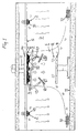
- the ventilating device according to Fig. 1 is intended to create a zone 1 of clean air between the ventilating device and a workplace region, here an operating region 2 in the healthcare sector.
- the ventilating device comprises air supply units 3 which may be of a conventional type and are adapted to generating laminar air flows intended to constitute said clean air zone 1.
- the ventilating device comprises at least three air supply units 3 disposed in a closed trilateral pattern of three air supply units.
- the clean air zone 1 has below the air supply units 3 an extent which in cross-section substantially corresponds to the surface delineated by said closed pattern of air supply units and the surface situated within that pattern, i.e. substantially the extent indicated by Fig. 1 .
- the ventilating device comprises in addition a corresponding number of, i.e. at least three, air stop and guide units 4 disposed between the respective pairs of mutually adjacent air supply units.
- the closed pattern of air supply units 3 may also be, for example, elliptical, square, rectangular or have five, six or more sides or a combination of different shapes.
- the air stop and guide units 4 are suitably disposed in corresponding patterns in the spaces delineated between mutually adjacent air supply units 3.
- Each air stop and guide unit 4 will with advantage also fill the whole space between two mutually adjacent air supply units 3.
- the number of air supply units 3 and the number of air stop and guide units 4 disposed between them each amount preferably to between 3 and 15, depending on the desired extent of the region to be served by the ventilating device.
- the number of air supply units 3 and air stop and guide units 4 is eight (8) each.
- the air supply units 3 and the air stop and guide units 4 disposed between them in the version depicted are mounted on a container 5.
- the container 5 is fitted permanently in the ceiling of the room in which the workplace region is situated, i.e. here in the ceiling 6 of the operating room 7 in which the operating region 2 defining or constituting the operating table 8 is situated.
- the container 5 comprises with advantage, or is connected via an air duct 9 to, at least one air intake for taking air in from the room 7 and/or from at least one location outside said room.
- at least one air intake for taking air in from the room 7 and/or from at least one location outside said room.
- some of the air drawn out of the room 7 via air extracts 10 at or near the floor 11 of the room may be led back to the air supply units 3 in the ventilating device.
- Air may also be brought from air intakes (not depicted) in or near the ceiling 6 of the room 7.
- the container 5 comprises with advantage, or is likewise connected via preferably the same air duct 9 to, a fan device (not depicted) for supplying air and causing it to flow through the air supply units 3.
- the container 5 comprises, or is connected preferably via same air duct 9 to, an air treatment device for generating clean air for the clean air zone 1.
- the air treatment device comprises in a simple version at least one filter device (not depicted) for filtering the air to the air supply units 3 so that the air will be clean and can constitute said clean air zone 1, and also a device (not depicted) for cooling of air from the filter device to a lower temperature than the temperature of the air in the room 7, so that clean air intended to constitute the clean air zone will be at such a lower temperature, e.g. 1-2°C lower, than air surrounding the clean air zone that clean air in the clean air zone sinks slowly downwards towards the workplace region, here the operating region 2.
- the higher density of the cooler air is thus used for controlling the downward velocity.
- the advantage of this is that the initial air velocity a few decimetres from the air supply units need not be greater than the air velocity required down at the workplace region for creating a sufficient velocity therein. Less disturbing effects, turbulence, and secondary air flows outside the workplace region are thereby generated, resulting in less risk of contamination of the workplace region. Low air velocity results in small air flow with high efficiency and, for personnel, a draught-free and quiet work environment.
- the level of the preferably constant lower temperature of the air in the clean air zone 1 relative to surrounding air in the room 7 is with advantage maintained by a regulating device (not depicted) which forms part of the ventilating device and which therefore regulates the temperature of the clean air in the clean air zone in order to regulate the velocity of the clean air in the clean air zone.
- the regulating device is controlled by temperature sensors of a suitable type (not depicted) situated with advantage in the container 14 or in the air flow before 9 and level with the operating table 8 in the operating room 7.
- the air supply units 3 and the air stop and guide units 4 disposed between them are preferably fitted at or in the vicinity of the outer periphery of the container 5 if the shape of the container is different from the closed pattern which said air supply units and air stop and guide units form.
- a lighting device with one or more lamps 12 suspended in arms 13 may be situated close to the container 5.
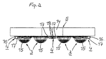
- the container 5 takes the form of a container 14 with the air supply units 3 and the air stop and guide units 4 disposed between them fitted on the underside of the container.
- the container 14 is here circular with a diameter of about 1 to 4 m.
- the closed circular pattern of air supply units 3 and air stop and guide units 4 runs along and close to the outer periphery of the container 14.
- the respective air supply units 3 in the ventilating device may be of the type described in, for example, PCT/SE2004/001182 .
- the respective air supply units 3 as seen from the side may preferably be of at least partly hemispherical or substantially hemispherical shape, resulting in a distinct clean air zone with a distinctly limited extent from each air supply unit.
- the respective air supply units 3 also preferably present a substantially circular cross-section.
- Each air supply unit 3 has a body 15 made of foam plastic or similar porous material or fabric adapted to generating laminar air flows, thereby minimizing the risk of air surrounding the clean air zone 1 entering the clean air zone.
- the body 15 may comprise an inner element and an outer element, the inner element imparting to air flowing through a greater pressure drop than the outer element.
- the inner element may be made of foam plastic or other porous material or fabric, while the outer element takes the form of, for example, tubular throughflow ducts.
- the length of these throughflow ducts is with advantage 4-10 times greater than their width, to ensure that the turbulence in at least an outer portion of the clean air zone 1 will be as little as possible.
- Other suitable types of air supply units with desired suitable functions may nevertheless be used in the ventilating device according to the present invention.
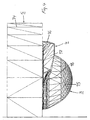
- each air stop and guide unit 4 comprises accordingly at least one air stop surface 16 which faces away from the clean air zone 1 and prevents or hinders air surrounding the clean air zone from being drawn in between adjoining air supply units 3 and into the clean air zone.
- Each air stop and guide unit 4 also comprises at least two first air guide surfaces 17 which run from the air stop surface 16 in between adjoining air supply units 3, converge towards one another and guide away from one another and out from the centre of the clean air zone 1 parts of the respective air flows directed towards one another from adjoining air supply units.
- Each air stop and guide unit 4 also comprises at least two second air guide surfaces 18 which face inwards towards the centre of the clean air zone 1 and towards said first air guide surfaces 17, converge towards one another and guide away from one another and inwards towards the centre of the clean air zone parts of the air flows directed towards one another from adjoining air supply units 3.
- This preferred version of the air stop and guide units 4 achieves the least possible turbulence between the air flows meeting between the air supply units 3 and prevents bacteria-bearing and other pollutant particles from being drawn into the clean air zone 1.
- the respective air stop and guide units 4, especially their first air guide surfaces 17, run here along at least about 90° of the periphery of adjoining air supply units.
- the air stop surface 16 on the air stop and guide units 4 has with advantage a configuration which in at least a cross-sectional plane through said surface and through the air supply units 3 coincides with the configuration of a line which links the outermost portions of the air supply units as seen from the clean air zone 1.
- the air stop surface 16 has accordingly a curvature which in said cross-sectional plane coincides with the curvature of a circular line which runs through the radially outermost portions of the air supply units (see Fig. 3 ).
- the air stop surface 16 is also preferably of such a length that it runs from the vicinity of the outermost portions of one of the two mutually adjacent air supply units 3 between which the respective air stop and guide unit 4 is disposed, to the vicinity of the outermost portions of the other of the two air supply units. This contributes to optimum filling of the space between each pair of mutually adjacent air supply units 3.
- the first air guide surfaces 17 on the respective air stop and guide unit 4 as seen in a cross-sectional plane converge towards one another preferably in a manner corresponding to the cross-sectional shape of adjoining air supply units 3, i.e. said surfaces run towards one another inwards towards the centre of the clean air zone 1 and have accordingly the same configuration as adjoining air supply units so that the distance between the first air guide surfaces and the air supply units is constant (see Fig. 3 ).
- the first air guide surfaces 17 as seen in a longitudinal sectional plane also converge towards one another, i.e. said surfaces run towards one another downwards to the workplace region 2 in the clean air zone 1 (see Figs. 2 and 4 ).
- the second air guide surfaces 18 run, as above, towards the first air guide surfaces 17 outwards from the centre of the clean air zone 1 and downwards towards the workplace region in the clean air zone (see Figs. 2-4 ). They also run towards one another downwards towards said workplace region (see Figs. 2 and 4 ).
- At least one further air supply unit 3 of preferably the type described above is disposed in the room 7 to supply air to the room. This air maintains with advantage a temperature exceeding the temperature of the air in the clean air zone 1, thereby compensating in particular for the cooling effect caused by the clean air zone 1.
- a plurality of further air supply units 3 are disposed all round the first-mentioned air supply units 3 and said air stop and guide units 4 (on the container 5) in the room 7 to supply the room round the clean air zone with somewhat warmer air than the air in the clean air zone 1.
- Said further air supply units 3 have their own, or are suitably connected at least to the aforesaid, fan and filter devices.
- the ventilating device comprises a regulating device (not depicted) for regulating the temperature of the air which is supplied to the room 7 and caused to surround the clean air zone 1, and/or for regulating the velocity of the air which is supplied to the room and is caused to surround the clean air zone.
- the temperature of the whole room 7 can thereby be regulated.
- the regulating device is controlled by temperature sensors (not depicted) situated in the room 7 outside the clean air zone 1.
- said fan, filter and cooling devices may be configured and disposed in any manner appropriate to the purpose, as also may said regulating devices.
- the number, type and shape of the air supply units and of the air stop and guide units may vary beyond what is indicated above, as also may how they are positioned relative to one another and how they are positioned on the container for the ventilating device.
- the shape of the container may also vary beyond what is indicated above and may also, as previously indicated, follow or not follow the closed pattern constituted by the air supply units and the air stop and guide units.
Landscapes
- Engineering & Computer Science (AREA)
- Health & Medical Sciences (AREA)
- Chemical & Material Sciences (AREA)
- Combustion & Propulsion (AREA)
- Mechanical Engineering (AREA)
- General Engineering & Computer Science (AREA)
- General Health & Medical Sciences (AREA)
- Life Sciences & Earth Sciences (AREA)
- Animal Behavior & Ethology (AREA)
- Public Health (AREA)
- Veterinary Medicine (AREA)
- Surgery (AREA)
- Biomedical Technology (AREA)
- Pulmonology (AREA)
- Ventilation (AREA)
Claims (15)
- Belüftungsvorrichtung zum Bereitstellen einer Zone (1) mit sauberer Luft in einem Raum (7) zwischen der Belüftungsvorrichtung und einem Arbeitsplatzbereich (2) in dem Raum, wobei die Belüftungsvorrichtung Luftversorgungseinheiten (3) aufweist, die eingerichtet sind, laminare Luftströmungen zu erzeugen, welche zur Bildung der Reinluftzone bestimmt sind, dadurch gekennzeichnet, dass die Belüftungsvorrichtung mindestens drei Luftversorgungseinheiten (3) aufweist, die in einer geschlossenen Struktur derart angeordnet sind, dass die Ausdehnung des Querschnitts der Reinluftzone (1) unterhalb der Luftversorgungseinheiten im Wesentlichen der Oberfläche entspricht, die durch die geschlossene Struktur der Luftversorgungseinheiten und der innerhalb der Struktur liegenden Oberfläche und einer entsprechenden Anzahl von Luftsperr- und Luftleitvorrichtungen (4), welche dazwischen angeordnet sind und im Wesentlichen den Raum dazwischen ausfüllen, eingegrenzt wird, wobei jedes Paar der aneinander angrenzenden Luftversorgungseinheiten (3), jede Luftsperr- und Luftleitvorrichtung (4) mindestens eine Luftsperrfläche (16) aufweist, die nach außen, weg von der Reinluftzone (1) gerichtet ist, und die verhindert oder erschwert, dass die Luft, welche die Reinluftzone umgibt, zwischen die nebeneinanderliegenden Luftversorgungseinheiten (3) und in die Reinluftzone gezogen wird, mindestens zwei erste Luftleitflächen (17) aufweist, die von der Luftsperrfläche zwischen den nebeneinanderliegenden Luftversorgungseinheiten verlaufen, aufeinander zu laufen und Anteile der Luftströme von nebeneinanderliegenden Luftversorgungseinheiten, die aufeinander zu gerichtet sind, voneinander weg und vom Zentrum der Reinluftzone ausgehend nach außen lenken, und mindestens zwei zweite Luftleitflächen (18) aufweist, die nach innen in Richtung des Zentrums der Reinluftzone gerichtet sind und in Richtung der ersten Luftleitflächen und aufeinander zu zusammenlaufen und andere Anteile der Luftströme von nebeneinanderliegenden Luftversorgungseinheiten, die aufeinander zu gerichtet sind, voneinander weg und nach innen in Richtung des Zentrums der Reinluftzone lenken.
- Belüftungsvorrichtung nach Anspruch 1, dadurch gekennzeichnet, dass die Luftversorgungseinheiten (3) in einer Struktur angeordnet sind, die kreisförmig ist, elliptisch ist oder drei, vier, fünf oder mehr Seiten oder Kombinationen davon aufweist, mit den Luftsperr- und Luftleitvorrichtungen (4) in einer entsprechenden Struktur in den Räumen, die zwischen den nebeneinanderliegenden Luftversorgungseinheiten eingegrenzt sind.
- Belüftungsvorrichtung nach Anspruch 1 oder 2, dadurch gekennzeichnet, dass die Anzahl der Luftversorgungseinheiten (3) und die Anzahl der Luftsperr- und Luftleitvorrichtungen (4), die zwischen diesen angeordnet sind, jeweils zwischen 3 und 15, vorzugsweise 8 liegt.
- Belüftungsvorrichtung nach einem der Ansprüche 1 - 3, dadurch gekennzeichnet, dass die Luftversorgungseinheiten (3) und die zwischen diesen angeordneten Luftsperrvorrichtungen (4) auf einer gemeinsamen Montagevorrichtung (5) befestigt sind, die dauerhaft in der Zimmerdecke (6) des Raums (7), in welchem sich der Arbeitsplatzbereich (2) befindet, eingebaut ist.
- Belüftungsvorrichtung nach Anspruch 4, dadurch gekennzeichnet, dass die Montagevorrichtung (5) eine Luftaufbereitungsvorrichtung aufweist oder über einen Luftschacht (9) damit verbunden ist, welche mindestens eine Filtervorrichtung zur Luftfilterung umfasst, um saubere Luft bereitzustellen, die für die Bildung der Reinluftzone (1) vorgesehen ist, und eine Vorrichtung zur Kühlung der Luft auf eine niedrigere Temperatur als die Temperatur der Luft in dem Raum (7), in welchem sich der Arbeitsplatzbereich (2) befindet, um es sauberer Luft, die für die Bildung der Reinluftzone vorgesehen ist, zu ermöglichen, bei einer solchen niedrigeren Temperatur als die Luft zu sein, welche die Reinluftzone umgibt, dass die saubere Luft in der Reinluftzone langsam nach unten in Richtung des Arbeitsplatzes sinkt.
- Belüftungsvorrichtung nach einem der Ansprüche 4 - 5, dadurch gekennzeichnet, dass die Luftversorgungseinheiten (3) und die Luftsperr- und Luftleitvorrichtungen (4), die zwischen diesen angeordnet sind, an oder in der Nähe des äußeren Randbereichs der Montagevorrichtung (5) eingebaut sind.
- Belüftungsvorrichtung nach einem der Ansprüche 4 - 6, dadurch gekennzeichnet, dass die Montagevorrichtung (5) in der Form einer Montagevorrichtung (14) ausgebildet ist, bei der Luftversorgungseinheiten (3) und die Luftsperr- und Luftleitvorrichtungen (4), die zwischen diesen angeordnet sind, an der Unterseite der Montagevorrichtung eingebaut sind.
- Belüftungsvorrichtung nach Anspruch 7, dadurch gekennzeichnet, dass die Montagevorrichtung (14) kreisförmig ist und einen Durchmesser von ungefähr 1 bis 4 m aufweist.
- Belüftungsvorrichtung nach einem der vorhergehenden Ansprüche, dadurch gekennzeichnet, dass die entsprechenden Luftversorgungseinheiten (3) einen mindestens teilweise halbkugelförmigen oder im Wesentlichen halbkugelförmigen longitudinalen Bereich aufweisen.
- Belüftungsvorrichtung nach einem der vorhergehenden Ansprüche, dadurch gekennzeichnet, dass die entsprechenden Luftversorgungseinheiten (3) einen im Wesentlichen kreisförmigen Querschnitt aufweisen.
- Belüftungsvorrichtung nach einem der vorhergehenden Ansprüche, dadurch gekennzeichnet, dass die entsprechenden Luftversorgungseinheiten (3) mindestens einen Körper aufweisen, der aus Schaumkunststoff oder entsprechend porösem Material oder Gewebe hergestellt ist und geeignet ist, laminare Luftströme zu erzeugen.
- Belüftungsvorrichtung nach einem der vorhergehenden Ansprüche, dadurch gekennzeichnet, dass die entsprechenden Luftversorgungseinheiten (3) mindestens einen Körper mit einem Innenelement und einem Außenelement aufweisen und dass das Innenelement der durchströmenden Luft einen größeren Druckabfall verleiht als das Außenelement.
- Belüftungsvorrichtung nach einem der vorhergehenden Ansprüche, dadurch gekennzeichnet, dass die entsprechenden Luftversorgungseinheiten (3) mindestens einen Körper mit einem Innenelement aufweisen, welches aus Schaumkunststoff oder anderem porösem Material oder Gewebe hergestellt ist, und einem Außenelement, welches aus röhrenförmigen Durchflusskanälen hergestellt ist, deren Länge 4 - 10-mal größer als ihre Breite ist, um sicherzustellen, dass die Verwirbelung in mindestens einem äußeren Abschnitt der Reinluftzone (1) so klein wie möglich ist.
- Belüftungsvorrichtung nach einem der vorhergehenden Ansprüche, dadurch gekennzeichnet, dass die entsprechenden Luftversorgungseinheiten (3) einen im Wesentlichen kreisförmigen Querschnitt aufweisen und dass die entsprechenden Luftsperr- und Luftleitvorrichtungen (4) in einem Winkel von ungefähr 90° entlang des Randbereichs der aneinander angrenzenden Luftversorgungseinheiten verlaufen.
- Belüftungsvorrichtung nach einem der vorhergehenden Ansprüche, dadurch gekennzeichnet, dass die Luftsperrfläche (16) eine Größe aufweist, bei der mindestens eine Querschnittsebene mit der Größe einer Linie übereinstimmt, welche die äußersten Abschnitte der Luftversorgungseinheiten (3), wie von der Reinluftzone (1) aus gesehen, miteinander verbindet, dass die Luftversorgungseinheiten (3) in einem Kreis angeordnet sind und dass die Luftsperrfläche (16) eine Krümmung aufweist, bei der mindestens eine Querschnittsebene mit der Krümmung einer Kreislinie übereinstimmt, welche durch die radial äußersten Abschnitte der Luftversorgungseinheiten (3) verläuft.
Applications Claiming Priority (2)
| Application Number | Priority Date | Filing Date | Title |
|---|---|---|---|
| SE0701074A SE532217C2 (sv) | 2007-05-03 | 2007-05-03 | Ventilationsanordning för en operationslokal |
| PCT/SE2008/050483 WO2008136740A1 (en) | 2007-05-03 | 2008-04-28 | Ventilating device for providing a zone of clean air |
Publications (3)
| Publication Number | Publication Date |
|---|---|
| EP2146676A1 EP2146676A1 (de) | 2010-01-27 |
| EP2146676A4 EP2146676A4 (de) | 2012-07-04 |
| EP2146676B1 true EP2146676B1 (de) | 2013-10-09 |
Family
ID=39943748
Family Applications (1)
| Application Number | Title | Priority Date | Filing Date |
|---|---|---|---|
| EP08779284.2A Active EP2146676B1 (de) | 2007-05-03 | 2008-04-28 | Belüftungsvorrichtung zur erzeugung eines bereichs mit sauberer luft |
Country Status (7)
| Country | Link |
|---|---|
| US (1) | US8308536B2 (de) |
| EP (1) | EP2146676B1 (de) |
| JP (1) | JP4987120B2 (de) |
| CN (1) | CN101784248B (de) |
| DK (1) | DK2146676T3 (de) |
| SE (1) | SE532217C2 (de) |
| WO (1) | WO2008136740A1 (de) |
Families Citing this family (20)
| Publication number | Priority date | Publication date | Assignee | Title |
|---|---|---|---|---|
| US20100120349A1 (en) * | 2008-10-31 | 2010-05-13 | Airsonett Ab | Surgical theater ventilating devices and methods |
| WO2010100559A1 (en) * | 2009-03-05 | 2010-09-10 | Airsonett Ab | Surgical instrument table ventilation devices and methods |
| AU2010348732B2 (en) * | 2010-03-16 | 2013-11-14 | Airsonett Ab | Treatment of asthma, allergic rhinitis and improvement of quality of sleep by Temperature controlled Laminar Airflow treatment |
| US9687415B2 (en) * | 2010-05-13 | 2017-06-27 | The Nemours Foundation | Extrathoracic augmentation of the respiratory pump |
| ES2545693T3 (es) * | 2011-04-06 | 2015-09-15 | Airsonett Ab | Dispositivo de flujo de aire laminar controlado por temperatura |
| US20130344795A1 (en) * | 2012-06-25 | 2013-12-26 | Huntair, Inc. | System and method for delivering air through a boom assembly |
| US20140242901A1 (en) * | 2013-02-22 | 2014-08-28 | Treasure Unicorn Limited | Airflow outlet of air-conditioning device |
| DE102013105287A1 (de) * | 2013-05-23 | 2014-11-27 | Gerresheimer Regensburg Gmbh | Reinraum zum Produzieren von Gegenständen und Verfahren zum Betreiben eines Reinraums |
| ES2699902T3 (es) | 2013-12-03 | 2019-02-13 | Avidicare Ab | Un sistema de suministro de aire |
| ES2897465T3 (es) | 2015-05-12 | 2022-03-01 | Halton Oy | Flujo de dilución controlada en entornos críticos |
| WO2017053979A1 (en) | 2015-09-25 | 2017-03-30 | Sprimo, Inc. | Localized ventilation systems and methods |
| US11186989B2 (en) * | 2015-10-07 | 2021-11-30 | Sld Technology, Inc. | Equipment support system and method of supporting equipment |
| US10337751B2 (en) * | 2016-08-04 | 2019-07-02 | Environmental Information Services, Inc. | Liquefied petroleum gas solvent extraction room ventilation system and methods |
| US20200078125A1 (en) | 2016-11-08 | 2020-03-12 | Optimus Licensing Ag | Integrated operating room sterilization system - design and components |
| US11408170B2 (en) * | 2019-02-06 | 2022-08-09 | Flexible OR Solutions LLC | Universal pre-fabricated operating room ceiling system |
| CN109914747B (zh) * | 2019-03-30 | 2024-04-26 | 单简 | 住宅排气道防倒灌排风帽 |
| US12016802B2 (en) | 2019-10-22 | 2024-06-25 | Aerobiotix. Llc | Air treatment system for operating or patient rooms |
| CA3198450A1 (en) * | 2020-10-14 | 2022-04-21 | Airsonett Ab | Improved device for providing a clean air zone, e.g. a controlled personal breathing zone |
| JP2022165935A (ja) * | 2021-04-20 | 2022-11-01 | フロージェヌイティ インコーポレイテッド | 周囲環境内で微小環境を生成するためのシステム |
| CN115111675B (zh) * | 2022-08-30 | 2022-12-13 | 苏州中卫宝佳净化科技有限公司 | 一种可改善湍流效应的温湿度调控型洁净室 |
Family Cites Families (33)
| Publication number | Priority date | Publication date | Assignee | Title |
|---|---|---|---|---|
| US3115819A (en) * | 1961-03-06 | 1963-12-31 | Sheffield Corp | Prefabricated enclosure |
| GB1015575A (en) * | 1962-08-06 | 1966-01-05 | Karl Tage Nordstrom | Improvements in or relating to an arrangement for producing an annular laminar air curtain |
| SE312656B (de) * | 1966-05-31 | 1969-07-21 | Ar Ventilation Ab | |
| US3626837A (en) * | 1970-02-13 | 1971-12-14 | Chs Ind Inc | Dual plenum for ventilating ceilings in clean rooms |
| SE345318B (de) * | 1970-09-04 | 1972-05-23 | C Allander | |
| US3726203A (en) * | 1971-06-23 | 1973-04-10 | Svenska Flaektfabriken Ab | Device for maintenance of a dustfree, bacteria-free zone in a room |
| US4137831A (en) * | 1976-05-08 | 1979-02-06 | Howorth Air Engineering Limited | Clean air zone |
| US4164173A (en) * | 1977-02-28 | 1979-08-14 | Douglas Andrew S M | Air supply systems for operating theatres |
| JPS626428Y2 (de) * | 1981-06-29 | 1987-02-14 | ||
| AU5779286A (en) * | 1985-04-26 | 1986-11-18 | MTD Medical Development and Technology Ltd. | Method and means for supplying clean air to an operating room |
| FI78548C (fi) * | 1986-12-30 | 1989-08-10 | Halton Oy | Luftfoerdelningssystem. |
| US4946484A (en) * | 1988-02-05 | 1990-08-07 | Donaldson Company, Inc. | Support for clean room ceiling grid system |
| SE500707C2 (sv) * | 1990-08-22 | 1994-08-15 | Jk Vvs Projektering Ab | Tilluftdon med halvsfärisk utströmningsdel uppvisande poröst material |
| US5454756A (en) * | 1991-08-21 | 1995-10-03 | Pace Company | Clean room ventilation system |
| US5192348A (en) * | 1991-08-21 | 1993-03-09 | Brod & Mcclung-Pace Co. | Directional air diffuser panel for clean room ventilation system |
| US5417610A (en) * | 1992-11-06 | 1995-05-23 | Daw Technologies, Inc. | Method and device for reducing vortices at a cleanroom ceiling |
| NO934439D0 (no) * | 1993-12-06 | 1993-12-06 | Aet Arbeidsmiljoe Og Energitek | Anordning ved takmontert ventilasjonsanlegg |
| US5904896A (en) * | 1995-12-08 | 1999-05-18 | A. R. Grindl | Multi-stage zonal air purification system |
| US5716268A (en) * | 1997-02-18 | 1998-02-10 | Plymovent Ab | Device for removal of deleterious impurities from room atmosphere |
| US6626971B1 (en) * | 1998-09-15 | 2003-09-30 | Siemens Axiva Gmbh & Co. Kg | Method and device for protecting persons and/or products from air-borne particles |
| SE513220C2 (sv) * | 1998-12-02 | 2000-07-31 | Johnson Medical Dev Pte Ltd | Sätt och anordning vid rumsventilation för s.k. renrum |
| SE516775C2 (sv) * | 2000-06-05 | 2002-02-26 | Jan Kristensson | Förfarande och anordning för att åstadkoma ren luft i en lokal |
| FR2824626B1 (fr) * | 2001-05-14 | 2004-04-16 | Pierre Bridenne | Procede et dispositif pour diffuser un flux de protection a l'egard d'une ambiance environnante |
| US6869458B2 (en) * | 2003-05-05 | 2005-03-22 | Sanki Engineering Co., Ltd. | Bioclean room unit |
| SE0302201D0 (sv) * | 2003-08-13 | 2003-08-13 | Airson Ab | Lufttillförselanordning |
| FR2865406B1 (fr) * | 2004-01-22 | 2007-11-30 | Acanthe | Diffuseur a effet parietal |
| KR100605106B1 (ko) * | 2004-07-01 | 2006-07-31 | 삼성전자주식회사 | 그레이팅 패널 및 그것을 사용하는 청정실 시스템 |
| US7022010B1 (en) * | 2004-08-31 | 2006-04-04 | Keith Cardon | Air conditioner with a circular air diffuser system |
| US20060063966A1 (en) * | 2004-09-17 | 2006-03-23 | Chan Daniel W | Patient isolation bed |
| JP4920197B2 (ja) * | 2005-04-05 | 2012-04-18 | 高砂熱学工業株式会社 | クリーンブース |
| US7462213B2 (en) * | 2005-10-26 | 2008-12-09 | Spengler Charles W | Method of minimizing cross contamination between clean air rooms in a common enclosure |
| WO2008004925A1 (en) | 2006-07-06 | 2008-01-10 | Camfil Ab | Air filter for clean rooms including inclined filter elements |
| US7645188B1 (en) * | 2007-09-17 | 2010-01-12 | Morris Peerbolt | Air diffuser apparatus |
-
2007
- 2007-05-03 SE SE0701074A patent/SE532217C2/sv unknown
-
2008
- 2008-04-28 JP JP2010506137A patent/JP4987120B2/ja active Active
- 2008-04-28 US US12/598,427 patent/US8308536B2/en active Active
- 2008-04-28 CN CN2008800220837A patent/CN101784248B/zh active Active
- 2008-04-28 EP EP08779284.2A patent/EP2146676B1/de active Active
- 2008-04-28 WO PCT/SE2008/050483 patent/WO2008136740A1/en active Application Filing
- 2008-04-28 DK DK08779284.2T patent/DK2146676T3/da active
Also Published As
| Publication number | Publication date |
|---|---|
| WO2008136740A1 (en) | 2008-11-13 |
| SE0701074L (sv) | 2008-11-04 |
| CN101784248B (zh) | 2013-01-16 |
| DK2146676T3 (da) | 2013-12-16 |
| SE532217C2 (sv) | 2009-11-17 |
| US20100291859A1 (en) | 2010-11-18 |
| CN101784248A (zh) | 2010-07-21 |
| US8308536B2 (en) | 2012-11-13 |
| JP2010526272A (ja) | 2010-07-29 |
| EP2146676A1 (de) | 2010-01-27 |
| EP2146676A4 (de) | 2012-07-04 |
| JP4987120B2 (ja) | 2012-07-25 |
Similar Documents
| Publication | Publication Date | Title |
|---|---|---|
| EP2146676B1 (de) | Belüftungsvorrichtung zur erzeugung eines bereichs mit sauberer luft | |
| JP5459776B2 (ja) | 気体拡散装置 | |
| EP2417957B1 (de) | OP-Saal-Belüftungsvorrichtungen und Verfahren | |
| EP0538524B1 (de) | System für örtlich begrenzte reine Luft und dazugehörender Verteilerkopf | |
| US4009647A (en) | Clean air zone for surgical purposes | |
| US20090288555A1 (en) | Method and device for providing a zone of clean air at an operation area and use of said device | |
| EP2881675B1 (de) | Luftzuführungssystem | |
| JP2019051316A (ja) | 個人化された空気浄化装置 | |
| JP2008256269A (ja) | 空調システムおよび空調方法 | |
| ES2897465T3 (es) | Flujo de dilución controlada en entornos críticos | |
| US20050250436A1 (en) | System, device and method for ventilation | |
| JP6153128B2 (ja) | 手術室用照明装置及びこれを備えた手術室 | |
| GB2135442A (en) | Air supply duct | |
| US20210190308A1 (en) | Lumiaire with integrated air multiplier | |
| EP2816294A2 (de) | Grillanordnung | |
| JP3236909U (ja) | 飛沫防止装置 | |
| CN114543324A (zh) | 气流控制系统 | |
| AU650486B2 (en) | Localised clean air system | |
| Air et al. | Application notes |
Legal Events
| Date | Code | Title | Description |
|---|---|---|---|
| PUAI | Public reference made under article 153(3) epc to a published international application that has entered the european phase |
Free format text: ORIGINAL CODE: 0009012 |
|
| 17P | Request for examination filed |
Effective date: 20091203 |
|
| AK | Designated contracting states |
Kind code of ref document: A1 Designated state(s): AT BE BG CH CY CZ DE DK EE ES FI FR GB GR HR HU IE IS IT LI LT LU LV MC MT NL NO PL PT RO SE SI SK TR |
|
| AX | Request for extension of the european patent |
Extension state: AL BA MK RS |
|
| RAP1 | Party data changed (applicant data changed or rights of an application transferred) |
Owner name: AIRSONETT AB |
|
| DAX | Request for extension of the european patent (deleted) | ||
| A4 | Supplementary search report drawn up and despatched |
Effective date: 20120605 |
|
| RIC1 | Information provided on ipc code assigned before grant |
Ipc: A61G 13/10 20060101ALI20120530BHEP Ipc: F24F 3/16 20060101ALI20120530BHEP Ipc: F24F 11/00 20060101ALI20120530BHEP Ipc: A61G 13/00 20060101AFI20120530BHEP Ipc: F24F 13/068 20060101ALI20120530BHEP |
|
| RAP1 | Party data changed (applicant data changed or rights of an application transferred) |
Owner name: AIRSONETT OPERATING ROOM INNOVATION AB |
|
| RIC1 | Information provided on ipc code assigned before grant |
Ipc: F24F 11/00 20060101ALI20130318BHEP Ipc: A61G 13/10 20060101ALI20130318BHEP Ipc: F24F 3/16 20060101ALI20130318BHEP Ipc: F24F 13/068 20060101ALI20130318BHEP Ipc: A61G 13/00 20060101AFI20130318BHEP |
|
| GRAP | Despatch of communication of intention to grant a patent |
Free format text: ORIGINAL CODE: EPIDOSNIGR1 |
|
| INTG | Intention to grant announced |
Effective date: 20130430 |
|
| GRAS | Grant fee paid |
Free format text: ORIGINAL CODE: EPIDOSNIGR3 |
|
| GRAA | (expected) grant |
Free format text: ORIGINAL CODE: 0009210 |
|
| AK | Designated contracting states |
Kind code of ref document: B1 Designated state(s): AT BE BG CH CY CZ DE DK EE ES FI FR GB GR HR HU IE IS IT LI LT LU LV MC MT NL NO PL PT RO SE SI SK TR |
|
| RAP1 | Party data changed (applicant data changed or rights of an application transferred) |
Owner name: AVIDICARE AB |
|
| REG | Reference to a national code |
Ref country code: GB Ref legal event code: FG4D |
|
| REG | Reference to a national code |
Ref country code: AT Ref legal event code: REF Ref document number: 635234 Country of ref document: AT Kind code of ref document: T Effective date: 20131015 Ref country code: CH Ref legal event code: EP |
|
| REG | Reference to a national code |
Ref country code: IE Ref legal event code: FG4D |
|
| REG | Reference to a national code |
Ref country code: DE Ref legal event code: R096 Ref document number: 602008028016 Country of ref document: DE Effective date: 20131205 |
|
| REG | Reference to a national code |
Ref country code: DK Ref legal event code: T3 Effective date: 20131209 |
|
| REG | Reference to a national code |
Ref country code: NL Ref legal event code: T3 |
|
| REG | Reference to a national code |
Ref country code: AT Ref legal event code: MK05 Ref document number: 635234 Country of ref document: AT Kind code of ref document: T Effective date: 20131009 |
|
| PG25 | Lapsed in a contracting state [announced via postgrant information from national office to epo] |
Ref country code: SI Free format text: LAPSE BECAUSE OF FAILURE TO SUBMIT A TRANSLATION OF THE DESCRIPTION OR TO PAY THE FEE WITHIN THE PRESCRIBED TIME-LIMIT Effective date: 20131009 |
|
| REG | Reference to a national code |
Ref country code: LT Ref legal event code: MG4D |
|
| PG25 | Lapsed in a contracting state [announced via postgrant information from national office to epo] |
Ref country code: LT Free format text: LAPSE BECAUSE OF FAILURE TO SUBMIT A TRANSLATION OF THE DESCRIPTION OR TO PAY THE FEE WITHIN THE PRESCRIBED TIME-LIMIT Effective date: 20131009 Ref country code: SE Free format text: LAPSE BECAUSE OF FAILURE TO SUBMIT A TRANSLATION OF THE DESCRIPTION OR TO PAY THE FEE WITHIN THE PRESCRIBED TIME-LIMIT Effective date: 20131009 Ref country code: NO Free format text: LAPSE BECAUSE OF FAILURE TO SUBMIT A TRANSLATION OF THE DESCRIPTION OR TO PAY THE FEE WITHIN THE PRESCRIBED TIME-LIMIT Effective date: 20140109 Ref country code: FI Free format text: LAPSE BECAUSE OF FAILURE TO SUBMIT A TRANSLATION OF THE DESCRIPTION OR TO PAY THE FEE WITHIN THE PRESCRIBED TIME-LIMIT Effective date: 20131009 Ref country code: HR Free format text: LAPSE BECAUSE OF FAILURE TO SUBMIT A TRANSLATION OF THE DESCRIPTION OR TO PAY THE FEE WITHIN THE PRESCRIBED TIME-LIMIT Effective date: 20131009 Ref country code: IS Free format text: LAPSE BECAUSE OF FAILURE TO SUBMIT A TRANSLATION OF THE DESCRIPTION OR TO PAY THE FEE WITHIN THE PRESCRIBED TIME-LIMIT Effective date: 20140209 Ref country code: BE Free format text: LAPSE BECAUSE OF FAILURE TO SUBMIT A TRANSLATION OF THE DESCRIPTION OR TO PAY THE FEE WITHIN THE PRESCRIBED TIME-LIMIT Effective date: 20131009 |
|
| PG25 | Lapsed in a contracting state [announced via postgrant information from national office to epo] |
Ref country code: ES Free format text: LAPSE BECAUSE OF FAILURE TO SUBMIT A TRANSLATION OF THE DESCRIPTION OR TO PAY THE FEE WITHIN THE PRESCRIBED TIME-LIMIT Effective date: 20131009 Ref country code: PL Free format text: LAPSE BECAUSE OF FAILURE TO SUBMIT A TRANSLATION OF THE DESCRIPTION OR TO PAY THE FEE WITHIN THE PRESCRIBED TIME-LIMIT Effective date: 20131009 Ref country code: AT Free format text: LAPSE BECAUSE OF FAILURE TO SUBMIT A TRANSLATION OF THE DESCRIPTION OR TO PAY THE FEE WITHIN THE PRESCRIBED TIME-LIMIT Effective date: 20131009 Ref country code: LV Free format text: LAPSE BECAUSE OF FAILURE TO SUBMIT A TRANSLATION OF THE DESCRIPTION OR TO PAY THE FEE WITHIN THE PRESCRIBED TIME-LIMIT Effective date: 20131009 Ref country code: CY Free format text: LAPSE BECAUSE OF FAILURE TO SUBMIT A TRANSLATION OF THE DESCRIPTION OR TO PAY THE FEE WITHIN THE PRESCRIBED TIME-LIMIT Effective date: 20131009 |
|
| PG25 | Lapsed in a contracting state [announced via postgrant information from national office to epo] |
Ref country code: PT Free format text: LAPSE BECAUSE OF FAILURE TO SUBMIT A TRANSLATION OF THE DESCRIPTION OR TO PAY THE FEE WITHIN THE PRESCRIBED TIME-LIMIT Effective date: 20140210 |
|
| REG | Reference to a national code |
Ref country code: DE Ref legal event code: R097 Ref document number: 602008028016 Country of ref document: DE |
|
| PG25 | Lapsed in a contracting state [announced via postgrant information from national office to epo] |
Ref country code: EE Free format text: LAPSE BECAUSE OF FAILURE TO SUBMIT A TRANSLATION OF THE DESCRIPTION OR TO PAY THE FEE WITHIN THE PRESCRIBED TIME-LIMIT Effective date: 20131009 |
|
| PLBE | No opposition filed within time limit |
Free format text: ORIGINAL CODE: 0009261 |
|
| STAA | Information on the status of an ep patent application or granted ep patent |
Free format text: STATUS: NO OPPOSITION FILED WITHIN TIME LIMIT |
|
| PG25 | Lapsed in a contracting state [announced via postgrant information from national office to epo] |
Ref country code: RO Free format text: LAPSE BECAUSE OF FAILURE TO SUBMIT A TRANSLATION OF THE DESCRIPTION OR TO PAY THE FEE WITHIN THE PRESCRIBED TIME-LIMIT Effective date: 20131009 Ref country code: IT Free format text: LAPSE BECAUSE OF FAILURE TO SUBMIT A TRANSLATION OF THE DESCRIPTION OR TO PAY THE FEE WITHIN THE PRESCRIBED TIME-LIMIT Effective date: 20131009 Ref country code: CZ Free format text: LAPSE BECAUSE OF FAILURE TO SUBMIT A TRANSLATION OF THE DESCRIPTION OR TO PAY THE FEE WITHIN THE PRESCRIBED TIME-LIMIT Effective date: 20131009 Ref country code: SK Free format text: LAPSE BECAUSE OF FAILURE TO SUBMIT A TRANSLATION OF THE DESCRIPTION OR TO PAY THE FEE WITHIN THE PRESCRIBED TIME-LIMIT Effective date: 20131009 |
|
| 26N | No opposition filed |
Effective date: 20140710 |
|
| REG | Reference to a national code |
Ref country code: DE Ref legal event code: R097 Ref document number: 602008028016 Country of ref document: DE Effective date: 20140710 |
|
| PG25 | Lapsed in a contracting state [announced via postgrant information from national office to epo] |
Ref country code: MC Free format text: LAPSE BECAUSE OF FAILURE TO SUBMIT A TRANSLATION OF THE DESCRIPTION OR TO PAY THE FEE WITHIN THE PRESCRIBED TIME-LIMIT Effective date: 20131009 Ref country code: LU Free format text: LAPSE BECAUSE OF FAILURE TO SUBMIT A TRANSLATION OF THE DESCRIPTION OR TO PAY THE FEE WITHIN THE PRESCRIBED TIME-LIMIT Effective date: 20140428 |
|
| REG | Reference to a national code |
Ref country code: CH Ref legal event code: PL |
|
| REG | Reference to a national code |
Ref country code: IE Ref legal event code: MM4A |
|
| PG25 | Lapsed in a contracting state [announced via postgrant information from national office to epo] |
Ref country code: CH Free format text: LAPSE BECAUSE OF NON-PAYMENT OF DUE FEES Effective date: 20140430 Ref country code: LI Free format text: LAPSE BECAUSE OF NON-PAYMENT OF DUE FEES Effective date: 20140430 |
|
| PG25 | Lapsed in a contracting state [announced via postgrant information from national office to epo] |
Ref country code: IE Free format text: LAPSE BECAUSE OF NON-PAYMENT OF DUE FEES Effective date: 20140428 |
|
| PG25 | Lapsed in a contracting state [announced via postgrant information from national office to epo] |
Ref country code: MT Free format text: LAPSE BECAUSE OF FAILURE TO SUBMIT A TRANSLATION OF THE DESCRIPTION OR TO PAY THE FEE WITHIN THE PRESCRIBED TIME-LIMIT Effective date: 20131009 |
|
| REG | Reference to a national code |
Ref country code: FR Ref legal event code: PLFP Year of fee payment: 9 |
|
| PG25 | Lapsed in a contracting state [announced via postgrant information from national office to epo] |
Ref country code: BG Free format text: LAPSE BECAUSE OF FAILURE TO SUBMIT A TRANSLATION OF THE DESCRIPTION OR TO PAY THE FEE WITHIN THE PRESCRIBED TIME-LIMIT Effective date: 20131009 |
|
| PG25 | Lapsed in a contracting state [announced via postgrant information from national office to epo] |
Ref country code: GR Free format text: LAPSE BECAUSE OF FAILURE TO SUBMIT A TRANSLATION OF THE DESCRIPTION OR TO PAY THE FEE WITHIN THE PRESCRIBED TIME-LIMIT Effective date: 20140110 |
|
| PG25 | Lapsed in a contracting state [announced via postgrant information from national office to epo] |
Ref country code: HU Free format text: LAPSE BECAUSE OF FAILURE TO SUBMIT A TRANSLATION OF THE DESCRIPTION OR TO PAY THE FEE WITHIN THE PRESCRIBED TIME-LIMIT; INVALID AB INITIO Effective date: 20080428 Ref country code: TR Free format text: LAPSE BECAUSE OF FAILURE TO SUBMIT A TRANSLATION OF THE DESCRIPTION OR TO PAY THE FEE WITHIN THE PRESCRIBED TIME-LIMIT Effective date: 20131009 |
|
| REG | Reference to a national code |
Ref country code: FR Ref legal event code: PLFP Year of fee payment: 10 |
|
| REG | Reference to a national code |
Ref country code: FR Ref legal event code: PLFP Year of fee payment: 11 |
|
| P01 | Opt-out of the competence of the unified patent court (upc) registered |
Effective date: 20230328 |
|
| PGFP | Annual fee paid to national office [announced via postgrant information from national office to epo] |
Ref country code: NL Payment date: 20240322 Year of fee payment: 17 |
|
| PGFP | Annual fee paid to national office [announced via postgrant information from national office to epo] |
Ref country code: GB Payment date: 20240319 Year of fee payment: 17 |
|
| PGFP | Annual fee paid to national office [announced via postgrant information from national office to epo] |
Ref country code: FR Payment date: 20240318 Year of fee payment: 17 Ref country code: DK Payment date: 20240318 Year of fee payment: 17 |
|
| PGFP | Annual fee paid to national office [announced via postgrant information from national office to epo] |
Ref country code: DE Payment date: 20240319 Year of fee payment: 17 |