EP2145109B1 - Diaphragm pump position control with offset valve axis - Google Patents
Diaphragm pump position control with offset valve axis Download PDFInfo
- Publication number
- EP2145109B1 EP2145109B1 EP08747303.9A EP08747303A EP2145109B1 EP 2145109 B1 EP2145109 B1 EP 2145109B1 EP 08747303 A EP08747303 A EP 08747303A EP 2145109 B1 EP2145109 B1 EP 2145109B1
- Authority
- EP
- European Patent Office
- Prior art keywords
- diaphragm
- valve
- transfer chamber
- spool
- fluid
- Prior art date
- Legal status (The legal status is an assumption and is not a legal conclusion. Google has not performed a legal analysis and makes no representation as to the accuracy of the status listed.)
- Active
Links
- 239000012530 fluid Substances 0.000 claims description 107
- 238000012546 transfer Methods 0.000 claims description 101
- 238000000034 method Methods 0.000 claims description 16
- 238000005086 pumping Methods 0.000 claims description 14
- 238000004891 communication Methods 0.000 claims description 9
- 239000007788 liquid Substances 0.000 claims description 2
- 239000003921 oil Substances 0.000 description 18
- 230000001360 synchronised effect Effects 0.000 description 8
- 230000008901 benefit Effects 0.000 description 4
- 230000008569 process Effects 0.000 description 4
- 230000008859 change Effects 0.000 description 3
- 238000006073 displacement reaction Methods 0.000 description 3
- 239000000463 material Substances 0.000 description 3
- 230000003068 static effect Effects 0.000 description 3
- 238000010276 construction Methods 0.000 description 2
- 238000013461 design Methods 0.000 description 2
- 239000010720 hydraulic oil Substances 0.000 description 2
- 239000003082 abrasive agent Substances 0.000 description 1
- 238000013459 approach Methods 0.000 description 1
- 230000000712 assembly Effects 0.000 description 1
- 238000000429 assembly Methods 0.000 description 1
- 239000000919 ceramic Substances 0.000 description 1
- 230000003247 decreasing effect Effects 0.000 description 1
- 230000007547 defect Effects 0.000 description 1
- 230000000694 effects Effects 0.000 description 1
- 230000005484 gravity Effects 0.000 description 1
- 230000000670 limiting effect Effects 0.000 description 1
- 238000012423 maintenance Methods 0.000 description 1
- 230000003449 preventive effect Effects 0.000 description 1
- 230000002829 reductive effect Effects 0.000 description 1
- 230000004044 response Effects 0.000 description 1
Images


Classifications
-
- F—MECHANICAL ENGINEERING; LIGHTING; HEATING; WEAPONS; BLASTING
- F04—POSITIVE - DISPLACEMENT MACHINES FOR LIQUIDS; PUMPS FOR LIQUIDS OR ELASTIC FLUIDS
- F04B—POSITIVE-DISPLACEMENT MACHINES FOR LIQUIDS; PUMPS
- F04B43/00—Machines, pumps, or pumping installations having flexible working members
- F04B43/02—Machines, pumps, or pumping installations having flexible working members having plate-like flexible members, e.g. diaphragms
- F04B43/06—Pumps having fluid drive
- F04B43/067—Pumps having fluid drive the fluid being actuated directly by a piston
-
- F—MECHANICAL ENGINEERING; LIGHTING; HEATING; WEAPONS; BLASTING
- F04—POSITIVE - DISPLACEMENT MACHINES FOR LIQUIDS; PUMPS FOR LIQUIDS OR ELASTIC FLUIDS
- F04B—POSITIVE-DISPLACEMENT MACHINES FOR LIQUIDS; PUMPS
- F04B43/00—Machines, pumps, or pumping installations having flexible working members
- F04B43/0009—Special features
- F04B43/0081—Special features systems, control, safety measures
-
- F—MECHANICAL ENGINEERING; LIGHTING; HEATING; WEAPONS; BLASTING
- F04—POSITIVE - DISPLACEMENT MACHINES FOR LIQUIDS; PUMPS FOR LIQUIDS OR ELASTIC FLUIDS
- F04B—POSITIVE-DISPLACEMENT MACHINES FOR LIQUIDS; PUMPS
- F04B43/00—Machines, pumps, or pumping installations having flexible working members
- F04B43/02—Machines, pumps, or pumping installations having flexible working members having plate-like flexible members, e.g. diaphragms
- F04B43/06—Pumps having fluid drive
- F04B43/073—Pumps having fluid drive the actuating fluid being controlled by at least one valve
-
- F—MECHANICAL ENGINEERING; LIGHTING; HEATING; WEAPONS; BLASTING
- F05—INDEXING SCHEMES RELATING TO ENGINES OR PUMPS IN VARIOUS SUBCLASSES OF CLASSES F01-F04
- F05B—INDEXING SCHEME RELATING TO WIND, SPRING, WEIGHT, INERTIA OR LIKE MOTORS, TO MACHINES OR ENGINES FOR LIQUIDS COVERED BY SUBCLASSES F03B, F03D AND F03G
- F05B2210/00—Working fluid
- F05B2210/10—Kind or type
- F05B2210/11—Kind or type liquid, i.e. incompressible
Definitions
- the present invention generally relates to fluid pumps and more specifically relates to hydraulically driven diaphragm pumps.
- Hydraulically driven diaphragm pumps can be divided into at least two groups.
- the first group includes pumps that use a different stroke for the hydraulic piston or plunger than that of the diaphragm. These pumps can be referred to as asynchronous pumps.
- Asynchronous pumps are commonly used for metering in large diaphragm pumps where it is desirable to have a large diameter diaphragm that only defects a small amount (a "short stroke").
- Short stroke diaphragms are typically driven by a much longer stroke hydraulic plunger or piston.
- the long stroke of the piston makes possible the use of a small diameter for the piston, which result in smaller loads on the crankshaft and crankcase that must move the piston through its stroke.
- the second group includes pumps where the diaphragm center moves the same distance as the hydraulic piston. These pumps can be referred to as synchronous pumps.
- the diaphragm position in synchronous pumps is controlled by a valve in the piston that maintains a constant distance between the piston and diaphragm center.
- asynchronous pumps are described in US 5,246,351 (Horn), US 5,667,368 (Augustyn), and US 4,883,412 (Malizard). These example pumps all use a similar approach to diaphragm position control. Each of these pumps momentarily adjusts the amount of oil at the top or bottom of every stroke. An overfill condition is detected when the diaphragm travels too far forward and reaches a limit of travel. This causes a higher than normal pressure of the hydraulic fluid, which causes a valve to momentarily open and release some of the excess fluid. This excess pressure is generated when the diaphragm reaches a stop, or simply the end point of deflection where higher pressure is required to move the diaphragm further.
- This pressure is not transmitted to the pumped fluid and therefore produces an unbalanced pressure drop across the diaphragm.
- This method of dealing with pressures created by overfill requires that the diaphragm includes materials and a configuration adequate to handle this unbalanced pressure without the diaphragm failing.
- This limitation on diaphragm materials and design results in the use of very large diameter, low deflection diaphragms that greatly increase the size and cost of the pump.
- asynchronous hydraulically driven pumps do not allow for the use of highly flexible elastomeric diaphragms that are relatively small and capable of undergoing large deflections for at least those reasons discussed above.
- the use of these types of diaphragms is limited to synchronous pumps.
- the piston stroke in a synchronous pump must be relatively short since it is limited to the diaphragm stroke. This makes the crankshaft and crankcase bear the higher loads of a larger diameter piston, making the drive side of the pump more expensive.
- Lofquist discloses a spool that moves with every stroke of the diaphragm to momentarily open ports between a fluid reservoir and the hydraulic chamber (e.g., transfer chamber) behind the diaphragm at the ends of the piston stroke.
- the ports and moving spool allow only a small pulse of fluid to pass with each stroke in order to correct an overfill or underfill condition.
- Lofquist has some significant disadvantages under conditions of extreme underfill or overfill (e.g., conditions caused by very low or very high pump inlet pressure for the pumped fluid). Under extreme overfill conditions, the small pulse of fluid permitted with each stroke is insufficient to immediately correct the overfill, which results in stressing of the diaphragm until enough strokes occurred to correct the overfill condition. Another shortcoming of Lofquist relates to the direction in which the diaphragm is biased. Under extreme conditions (e.g., low inlet and outlet pressure for the pumped fluid caused by, for example, a blocked inlet to the pump), the Lofquist system tends to add oil to the transfer chamber without any bias applied to the diaphragm that would otherwise discharge the overfill of oil. As a result, the overfill cannot be solved and the diaphragm will fail.
- extreme underfill or overfill e.g., conditions caused by very low or very high pump inlet pressure for the pumped fluid.
- US 2006/239840 A1 discloses a hydraulically driven pump including a diaphragm, a piston, a transfer chamber, a fluid reservoir, and a spool member.
- the transfer chamber is defined between the diaphragm and piston and is filled with a hydraulic fluid.
- the fluid reservoir is in fluid communication with the transfer chamber via at least one valve.
- the spool member is configured to control fluid flow between the transfer chamber and the fluid reservoir. The spool member is movable to open and close an opening into the at least one valve only when an overfill condition or an underfill condition exists in the transfer chamber.
- US 2004/228748 A1 discloses a diaphragm pump which overcomes the problem of diaphragm failure due to overfill of the oil transfer chamber.
- An overfill preventive element in the form of a mechanical stop, a fully closed coil spring, or a valve system, or alternatives are provided.
- a diaphragm pump that includes a piston, a diaphragm, pumping and transfer chambers, first and second valves, a fluid reservoir, and a valve spool.
- the piston is adapted for reciprocal movement between a first position and a second position.
- the diaphragm is movable between first and second positions that correlate with the first and second piston positions.
- the transfer chamber is positioned on one side of the diaphragm and is defined in part by the relative positions of the diaphragm and the piston.
- the transfer chamber is filled with a hydraulic fluid.
- the pumping chamber is positioned on an opposing side of the diaphragm from the transfer chamber.
- the fluid reservoir is in fluid communication with the transfer chamber via the first and second valves.
- the valve spool is positioned in the transfer chamber and arranged to cover access openings of the first and second valves when the valve spool is in a first position, to cover the opening of the first valve and open the opening of the second valve when the valve spool is in a second position, and to open the opening of the first valve and close the opening of the second valve when the valve spool is in a third position.
- the spool typically maintains the first position until an overfill condition is generated in the transfer chamber that moves the spool to the second position, or until an underfill condition is generated in the transfer chamber that moves the spool to the third position.
- the pump further includes an actuating member that is attached to the moving portion of the diaphragm that engages the spool to move the spool between the first, second and third positions.
- the actuating member permits placement of the spool on a different axis than the rod and spring that are used to provide the diaphragm bias pressure.
- the spool can be positioned on a separate axis from the diaphragm, the diaphragm rod and spring, and the main piston of the pump.
- the present disclosure generally relates to fluid pumps such as hydraulically driven diaphragm pumps. Principles of the present disclosure are equally applicable to asynchronous and synchronous pumps. In asynchronous pumps there is a different stroke for the hydraulic piston versus a stroke of the diaphragm.
- the diaphragm is typically relatively large in diameter and is configured to deflect a relatively small amount.
- This short stroke diaphragm is driven by a much larger stroke hydraulic plunger or piston. The longer the stroke of the hydraulic plunger or piston, the smaller the diameter of the piston is required, which imparts smaller loads on the crankshaft and crankcase of the pump.
- Synchronous pumps are configured such that the center of the diaphragm moves the same distance as the hydraulic piston moves.
- the diaphragm must deflect large distances corresponding to the piston stroke in order to minimize loads on the crankcase and crankshaft resulting from use of a relatively small diameter piston. If it is not possible for the diaphragm to deflect to the extent necessary to ensure a relatively small diameter piston, the piston diameter must be enlarged, thus creating greater loads on the crankshaft and crankcase.
- the present disclosure can be used with either of asynchronous or synchronous pumps to help control a position of the diaphragm to ensure that the diaphragm does not extend or retract beyond predetermined distances that may otherwise lead to failure of the diaphragm.
- Many known diaphragm position control systems function based on hydraulic pressure conditions within the transfer chamber on a side of the diaphragm opposite of the fluid being pumped.
- Such pressure-based systems typically utilize relief valves that open or close in response to certain pressure levels.
- the relief valves are typically positioned between the hydraulic chamber and a reservoir of hydraulic fluid.
- the relief valve momentarily opens to release some of the hydraulic fluid to the reservoir when a maximum pressure is surpassed.
- a separate relief valve momentarily opens to draw some hydraulic fluid from the reservoir into the hydraulic chamber when the pressure drops below a minimum pressure.
- Overpressure is typically generated in such systems at the point where the diaphragm reaches a stop such as at the end of deflection where high pressure is required to deflect the diaphragm further.
- the diaphragm In order to account for the overpressure conditions, the diaphragm must be made of a relatively strong, inflexible material that can resist failure after repeated cycles of high and low pressure. Increasing the diameter and decreasing the amount of deflection the diaphragm must make can also account for the high pressure conditions, but can also greatly increase the size and cost of the pump.
- the present disclosure functions based on volume rather than pressure within the hydraulic chamber.
- a movable valve spool shifts in the hydraulic chamber between positions covering or uncovering openings to check valves that are positioned between a hydraulic reservoir and the hydraulic chamber. It is the fluid itself rather than a pressure condition generated by the fluid that moves the valve spool.
- the underfill and overfill volume conditions are typically best assessed at either the top or bottom of the piston stroke.
- the present disclosure is configured such that the valve spool moves only at the top or bottom of the piston stroke to correct the underfill or overfill condition.
- Applicant's co-pending U.S. Published Patent Application No. 2006/0239840 which is incorporated herein by reference, describes a system for controlling the position of a diaphragm in a hydraulically driven diaphragm pump so the diaphragm operates within a safe range of travel. That system uses a valve spool that is moved when the oil-filled transfer chamber is either overfilled or underfilled. When the transfer chamber is overfilled with oil, the diaphragm travels too far forward when the piston is at the top of the piston stroke. This overfilled position moves the valve spool, opening a port that allows the oil to leave the transfer chamber through a first one-way valve. When the transfer chamber is underfilled, the diaphragm travels too far back, thereby moving the valve spool so that the valve spool exposes a port that allows oil to come into the transfer chamber through a second one-way valve.
- Publication 2006/0239840 shows the valve spool positioned along the axis of the diaphragm, which is co-axial with a rod attached to the center of the diaphragm.
- This diaphragm rod generally is used to oppose the force of a bias spring that puts a slightly higher pressure on the oil in the transfer chamber than the fluid being pumped on the other side of the diaphragm.
- the rod also has a feature that comes in contact with the spool when overfill or underfill conditions exist, thereby moving the valve as described above.
- the coaxial spool must be designed to come into contact with the feature on the rod, while at the same time allowing for the coaxial spring that resides either inside or outside of the diaphragm rod.
- the overall structure and configuration for the diaphragm pump disclosed in publication 2006/0239840 tends to be relatively complicated, difficult to assemble, and can result in undesirable sizes for the spool and other components.
- the present disclosure provides for simpler components and structure for the control valve system than those used in, for example, publication 2006/0239840 .
- On such component is an actuating member that is attached to a moving portion of the diaphragm.
- the actuating member engages the valve spool to control oil flow between the transfer chamber and oil reservoir during overfill and underfill conditions.
- the actuating member permits positioning of the valve spool on a different axis than the axis of the diaphragm rod and spring that are used to provide the diaphragm bias pressure.
- Positioning the valve spool on a separate axis can simplify the diaphragm pump in several ways. For example, the diaphragm rod and bias pressure spring are required only to provide the limited function of applying a pressure bias.
- the size of the spring can be made smaller and the bore that the spring fits into is smaller (in the case of positioning the spring internal of the diaphragm rod). Further, the spool member does not require the highly smooth finish that the bore for a valve spool requires.
- valve spool can now be much smaller in diameter. Since the spool no longer needs to have a hole along its axis to house the diaphragm biasing spring, the spool can be much smaller in diameter and the corresponding bore that houses the spool can also be much smaller.
- the smaller bores for both the diaphragm bias spring and spool provides exposure of less area in the pump housing to the high pressure generated in the transfer chamber, which results in lower stress forces in the pump generally.
- the smaller bores also results a reduced volume of oil needed in the transfer chamber, which results in a lower bulk modulus for the system and higher volumetric efficiency.
- valve spool no longer requires a cylindrical shape.
- the valve spool can include a flat construction such as a ceramic disc member or other structure.
- a flat construction can provide the option of creating relative low clearance seal interfaces, and in some cases a lower cost design.
- FIG. 1 illustrates the pump piston at bottom dead center (BDC) with a normal fill condition.
- Figure 2 illustrates the piston at a top dead center (TDC) with a normal fill condition.
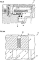
- Figure 3 illustrates the piston at BDC with an underfill condition.
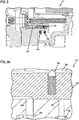
- Figure 4 illustrates the piston at a top dead center (TDC) with an overfill condition.
- Pump 10 includes a crankcase 12, a piston housing 14, and a manifold 16.
- the piston housing 14 defines a reservoir 18, a transfer or hydraulic chamber 20, and a plunger chamber 22.
- the manifold 16 defines a pumping chamber 24 and includes inlet and outlet valves 72, 74.
- a crankshaft 26, connecting rod 28, and slider 30 are positioned within the crankcase 12.
- the slider 30 is coupled to a plunger 32 positioned within the plunger chamber 22.
- the transfer and plunger chambers 20, 22 are in fluid communication with each other such that fluid drawn into or forced out of the plunger chamber 22 draws the diaphragm into a retracted position or forces the diaphragm into an extended position as shown in Figures 1 and 2 , respectively.
- a diaphragm rod 34 extends through the transfer chamber 20.
- a spring 36 is positioned co-axially with the rod 34 to exert a biasing force on the diaphragm in a rearward direction to help maintain a higher pressure condition in the transfer chamber 20 than in the pumping chamber 24. Maintaining a higher pressure condition in the transfer chamber 20 can improves performance of the pump 10 under suction inlet conditions.
- a spool bore 54 is defined in the piston housing 14 adjacent to the diaphragm rod 34.
- the spool bore is sized to receive a valve spool 42.
- the spool recess 52 is sized such that the valve spool 42 that is movable in a direction parallel with movement of the diaphragm rod 34.
- the valve spool 42 is movable between a first position providing access to an opening 56 of an underfill valve 44 and covering an opening 64 of an overfill valve 46 (see the underfill orientation of Figures 2, 2A ), a second position substantially covering openings 56, 64 (see the steady-state orientation of Figures 3, 3A ), and a third position covering opening 56 and providing access to opening 64 (see the overfill orientation of Figure 4, 4A ).
- the close-up views of Figures 2A , 3A and 4A illustrate more clearly the open or closed state of the openings 56, 64 in each of the steady-state, underfill, , and overfill conditions.
- the diaphragm pump 10 includes an underfill valve 44 associated with the opening 56, and an overfill valve 46 associated with the opening 64.
- the underfill valve 44 includes another opening 57 positioned adjacent to the hydraulic chamber 18.
- the underfill valve 44 also includes a seat 58, a spring 60, and a plug 62.
- the spring 60 biases the plug 62 against the seat 58 until the spool 42 is moved to uncover the opening 56.
- the overfill valve 46 includes a seat 66, a ball 68 and a spring 70.
- the spring 70 biases the ball 68 against the seat 66 until the spool 42 is moved to uncover the opening 64.
- the underfill and overfill valves 44, 46 are check valves that permit one-way fluid flow.
- the valve spool 42 provides an important function of controlling fluid flow between the transfer chamber 20 and the reservoir 18 during underfill, overfill, and steady-state conditions in the transfer chamber 20.
- the valve spool 42 moves depending on a position of the diaphragm 42.
- One end of a valve arm 43 is mounted to the diaphragm 33 and an opposing end of the valve arm 43 is positioned in a spool recess 52 of the valve spool 42.
- the spool recess 52 has a length greater than the amount of movement of the diaphragm 33 during steady-state operating conditions.
- the spool recess 52 provides a "dwell zone", wherein the valve arm 43 can freely move without moving the valve spool 42 until an overfill or underfill condition occurs in the transfer chamber 20.
- Movement of the spool 42 into the other positions shown in Figures 3, 3A , 4, 4A depends on the pumping conditions for the pump 10.
- a first common condition occurs at startup of the pump 10.
- fluid from the transfer chamber leaks out through the clearance between plunger piston 32 and the bore 31 due to pressure applied to the diaphragm 33 from the spring 36, or from residual pressure within the pump 10.
- the pump 10 is restarted, there is too little fluid in the transfer chamber 20, which results in the diaphragm 33 traveling too far rearward in the transfer chamber 20 when the plunger piston 32 is at BDC (e.g., see Figures 3, 3A .
- This condition is the underfill condition referenced above.
- valve arm 21 which moves with the diaphragm 33, moves the spool 42 so that the spool 42 completely covers the overfill opening 64 and exposes the underfill opening 56 (see Figures 3, 3A ).
- the valve arm 43 engages the valve spool 42 forward to eventually attain steady-state equilibrium position described above with reference to Figures 1 , 2, 2A .
- the second common condition occurs when there is a restriction on the inlet line to the pump 10 that causes a low pressure inlet condition and a loss of outlet pressure.
- the low pressure inlet condition permits the diaphragm 33 to travel further forward than normal when the plunger is at top dead center (TDC).
- TDC top dead center
- This condition is called the overfill condition and is shown with reference to Figures 4, 4A .
- the valve arm 43 urges the spool 42 forward so that the spool 42 completely covers the underfill opening 56 and exposes the overfill opening 64. Excess fluid is then permitted to travel out of the transfer chamber 20 through the overfill opening 56 and overfill valve 46 and into the reservoir 18.
- the spool will seek an equilibrium position to match the flow of fluid leaving and entering the transfer chamber 20.
- the position of the spool 42 remains unchanged until the pumping conditions change causing the valve arm 43 to move the spool 42.
- the pump 10 should include a device that inhibits movement of the spool 42 until engaged by the valve arm 43.
- a spool retainer 90 having a ball 92 and spring 94 are positioned in a spool retainer recess 96 in the spool 42. The spool retainer 90 generates a friction force against the spool bore so the spool 42 does not move on its own.
- the diaphragm stroke position will move by about 1/200 of the diaphragm stroke.
- the diaphragm 33 travel would be about 3,81 cm (1,5 inches), so the decrease in BDC per stroke is about 0,019 cm (0,0075 inches)
- the stroke position of the diaphragm will move 0,019 cm (0,0075 inches) back with each stroke until the spool 42 starts to uncover the underfill opening 56.
- the underfill opening 56 is slightly open, a small amount of fluid enters the transfer chamber 20 on each suction stroke. That oil coming in is subtracted from the rate of fluid leaving the transfer chamber 42 via the plunger piston 32 so that the net loss per stroke is less on the next stroke.
- the fluid entering the transfer chamber 20 on the suction stroke could be 0.5 cc and the net fluid leaving the transfer chamber 20 is now only 0.5 cc.
- the next stroke will only move the spool 42 by half as much as the previous movement, and continues to make smaller adjustments with each stroke.
- this adjustment process takes several strokes of the pump 10 and less than a few seconds of time, depending on the pump operation settings. The same process occurs when the pumping conditions are causing an overfill condition. An overfill condition occurs when the inlet to the pump 10 is restricted and there is low pressure on the outlet of the pump 10.
- Figure 1 further illustrates an air bleed valve 98 that is designed to allow air to escape from the transfer chamber 20 (e.g., during pump startup), but prevents significant liquid (e.g., hydraulic fluid or oil) leakage during normal operation.
- a wiper seal 99 is positioned on the plunger 32 to contain the hydraulic oil in the reservoir 18. This seal is not configured to maintain the high pressure of the transfer chamber 20. The high pressure of the transfer chamber 20 is maintained by a close fit between the plunger 32 and the bore 31. Fluid that passes through this high pressure clearance between plunger 32 and bore 31 is maintained at the same pressure as the reservoir 18, and the wiper seal 99 helps keep the fluid in the reservoir 18 so that the fluid is separate from the oil held in crankcase 12.
- Pump 100 includes many of the same features as described above with reference to Figures 1-4A .
- Pump 100 includes a different valve spool 142 that is operated using a lever 80.
- the valve spool 142 is positioned in a spool bore 154 that is offset from the diaphragm rod 34.
- the valve spool 142 is movable in a direction parallel with the direction of movement of the diaphragm rod 34 and diaphragm 33.
- the lever 80 operatively couples the diaphragm rod 34 with the spool valve 42.
- the lever 80 includes a fulcrum 81, and first and second connections 83, 84.
- the lever 80 pivots about the fulcrum 81.
- the first connection 83 is coupled to the diaphragm rod 34.
- the second connection 84 is coupled to the valve spool 42.
- the first connection 83 provides sliding engagement of the lever 80 on the diaphragm rod 34.
- a pair of first and second stops 85, 86 are positioned along the diaphragm rod 34 to control the distance of travel for the lever 80 along the diaphragm rod 34.
- the space defined between the stops 85, 86 define a "dwell zone" that permit the valve spool 42 to remain stationary during steady-state operation of the pump 10 until occurrence of an overfill or underfill condition in the transfer chamber 20.
- the diaphragm 33 In an underfill condition, the diaphragm 33 is permitted to move further rearward in the transfer chamber 20, causing the stop 86 to rotate the lever 80 about the fulcrum 81 to move the valve spool 42 forward to expose the underfill opening 56.
- the diaphragm 33 moves further forward than in a steady-state condition, causing the stop 85 to rotate the lever 80 about the fulcrum 81 to move the valve spool 42 rearward to expose the overfill opening 64.
- valve spool and related overfill and underfill valves can be combined together as a pre-assembled product that is mounted as a single piece within the pump.
- the valve spool can be arranged so that it moves in a direction perpendicular (or any non-parallel direction) relative to the direction of movement of the diaphragm rod and diaphragm.
- the valve spool can be positioned laterally to the side or vertically above the diaphragm rod, as opposed to the position of the valve spool vertically below the diaphragm rod as shown in Figures 1-6A .
- valve spool described with reference to the above examples can maintain a static position so long as there is a correct amount of hydraulic oil in the transfer chamber behind the diaphragm.
- the valve spool can maintain this static state regardless of the position of the diaphragm during its stroke between fully extended and fully retracted positions.
- the valve spool covers openings to the check valves positioned between the transfer chamber and the fluid reservoir.
- the valves are typically operated only when an overfill or underfill condition is present such that the valve spool moves to expose an opening to one or the other check valve.
- the limited operation of the relief valves provides some advantages over pressure-based systems in which the relief valve is actuated at the top or bottom of every piston stroke. The more a valve is operated, the more susceptible the valve is to wear.
- Another advantage of the example pumps described herein relates to the number of components necessary to correct both overfill and underfill conditions in the pump. Pressure-based systems typically require separate components to address overfill conditions versus underfill conditions.
- the example pumps described herein use a single spool member to correct both overfill and underfill conditions.
- the example valve spools disclosed herein function in conjunction with a pair of relatively simple check valves that receive little wear and use because they are only activated when an overfill or underfill condition is present. The limited activity of the valve spools limits wear and reduces the possibility for maintenance.
- a diaphragm pump that includes a diaphragm, a pumping chamber, a transfer chamber, first and second fluid valves, a fluid reservoir, and a valve spool.
- the diaphragm is movable between first and second positions along a first axis.
- the pumping chamber is defined on one side of the diaphragm and is adapted to carry a fluid to be pumped.
- the transfer chamber is defined on the opposite side of the diaphragm and is filled with a hydraulic fluid.
- the first and second valves are configured as one-way valves.
- the fluid reservoir is in fluid communication with the transfer chamber via the first and second valves.
- the valve spool is positioned in the transfer chamber to control fluid flow through the first and second valves.
- the valve spool is moveable along a second axis that is different from the first axis between a plurality of positions relative to openings of the first and second valves.
- a hydraulically driven pump that includes a diaphragm, a piston, a transfer chamber, a fluid reservoir, and a spool member.
- the diaphragm is moveable about a first axis.
- the transfer chamber is defined between the diaphragm and the piston, and is filled with a hydraulic fluid.
- the fluid reservoir is in fluid communication with the transfer chamber via at least one valve.
- the spool member is configured to control fluid flow between the transfer chamber and the fluid reservoir.
- the spool member is moveable relative to the at least one valve when an overfill condition or an underfill condition exists in the transfer chamber.
- the spool member is arranged non-coaxial with the first axis.
- a further aspect of the present disclosure relates to a method of balancing fluid pressure in a hydraulically driven diaphragm pump.
- the diaphragm pump includes a diaphragm, a piston, a transfer chamber interposed between the diaphragm and the piston, a fluid reservoir, a valve spool, and at least one valve providing fluid communication between the fluid reservoir and the transfer chamber.
- the method steps include moving the piston to move the diaphragm along a first axis, and moving the valve spool relative to the at least one valve member to control fluid flow between the fluid reservoir and the transfer chamber.
- the valve spool moves along a second axis that is non-coaxial with the first axis.
Landscapes
- Engineering & Computer Science (AREA)
- Mechanical Engineering (AREA)
- General Engineering & Computer Science (AREA)
- Reciprocating Pumps (AREA)
- Compressors, Vaccum Pumps And Other Relevant Systems (AREA)
Priority Applications (1)
| Application Number | Priority Date | Filing Date | Title |
|---|---|---|---|
| PL08747303T PL2145109T3 (pl) | 2007-05-02 | 2008-05-01 | Sterowanie położeniem pompy membranowej z przesuniętą osią zaworu |
Applications Claiming Priority (2)
| Application Number | Priority Date | Filing Date | Title |
|---|---|---|---|
| US11/743,505 US7665974B2 (en) | 2007-05-02 | 2007-05-02 | Diaphragm pump position control with offset valve axis |
| PCT/US2008/062169 WO2008137515A1 (en) | 2007-05-02 | 2008-05-01 | Diaphragm pump position control with offset valve axis |
Publications (2)
| Publication Number | Publication Date |
|---|---|
| EP2145109A1 EP2145109A1 (en) | 2010-01-20 |
| EP2145109B1 true EP2145109B1 (en) | 2017-04-05 |
Family
ID=39619136
Family Applications (1)
| Application Number | Title | Priority Date | Filing Date |
|---|---|---|---|
| EP08747303.9A Active EP2145109B1 (en) | 2007-05-02 | 2008-05-01 | Diaphragm pump position control with offset valve axis |
Country Status (11)
| Country | Link |
|---|---|
| US (1) | US7665974B2 (ru) |
| EP (1) | EP2145109B1 (ru) |
| JP (1) | JP5259695B2 (ru) |
| KR (1) | KR101401213B1 (ru) |
| CN (1) | CN101743403B (ru) |
| BR (1) | BRPI0811471B1 (ru) |
| DK (1) | DK2145109T3 (ru) |
| EA (1) | EA016439B1 (ru) |
| ES (1) | ES2632131T3 (ru) |
| PL (1) | PL2145109T3 (ru) |
| WO (1) | WO2008137515A1 (ru) |
Families Citing this family (28)
| Publication number | Priority date | Publication date | Assignee | Title |
|---|---|---|---|---|
| TW201024526A (en) * | 2008-12-23 | 2010-07-01 | Cheng-Chin Kung | Cooling and circulating system for engine oil |
| WO2011005571A2 (en) * | 2009-06-23 | 2011-01-13 | Weir Spm, Inc. | Readily removable pump crosshead |
| US20100325888A1 (en) * | 2009-06-30 | 2010-12-30 | Weir Spm, Inc. | Carrier for plunger during disassembly |
| US9157468B2 (en) | 2010-06-04 | 2015-10-13 | S.P.M. Flow Control, Inc. | Packing nut lock and method of use |
| DE102010039831B4 (de) * | 2010-08-26 | 2022-02-03 | Prominent Gmbh | Membranpumpe sowie Verfahren zum Einstellen einer solchen |
| WO2012083179A2 (en) | 2010-12-16 | 2012-06-21 | S.P.M. Flow Control, Inc. | Plunger packing with wedge seal having extrusion recess |
| USD748228S1 (en) | 2013-01-31 | 2016-01-26 | S.P.M. Flow Control, Inc. | Valve seat |
| US20130202457A1 (en) | 2012-02-03 | 2013-08-08 | S.P.M. Flow Control, Inc. | Pump assembly including fluid cylinder and tapered valve seats |
| DE102012106848A1 (de) | 2012-07-27 | 2014-01-30 | Prominent Dosiertechnik Gmbh | Dosieranlage sowie Dosierpumpe hierfür |
| USD726224S1 (en) | 2013-03-15 | 2015-04-07 | S.P.M. Flow Control, Inc. | Plunger pump thru rod |
| US8707853B1 (en) | 2013-03-15 | 2014-04-29 | S.P.M. Flow Control, Inc. | Reciprocating pump assembly |
| DE102013105072A1 (de) * | 2013-05-16 | 2014-11-20 | Prominent Gmbh | Membranpumpe mit Lagensteuerung |
| US9845794B2 (en) * | 2013-10-08 | 2017-12-19 | Ingersoll-Rand Company | Hydraulically actuated diaphragm pumps |
| FR3021713B1 (fr) * | 2014-05-27 | 2019-04-05 | Milton Roy Europe | Pompe a membrane a commande hydraulique comprenant un chemin de degazage dedie |
| EA201692452A1 (ru) | 2014-06-27 | 2017-05-31 | Эс.Пи.Эм. ФЛОУ КОНТРОЛ, ИНК. | Система демпфирования колебаний в кинематической цепи привода насоса и системы и способы управления для нее |
| AU2015292348B2 (en) | 2014-07-25 | 2018-12-06 | Spm Oil & Gas Inc. | Support for reciprocating pump |
| US9964106B2 (en) * | 2014-11-04 | 2018-05-08 | Wanner Engineering, Inc. | Diaphragm pump with dual spring overfill limiter |
| CN107208625A (zh) | 2014-12-22 | 2017-09-26 | S.P.M.流量控制股份有限公司 | 具有双回路动力端润滑系统的往复泵 |
| US11448210B2 (en) | 2015-07-02 | 2022-09-20 | Spm Oil & Gas Inc. | Valve for reciprocating pump assembly |
| US10221848B2 (en) | 2015-07-02 | 2019-03-05 | S.P.M. Flow Control, Inc. | Valve for reciprocating pump assembly |
| ITUB20151971A1 (it) * | 2015-07-06 | 2017-01-06 | Seko Spa | Pompa a membrana |
| USD759728S1 (en) | 2015-07-24 | 2016-06-21 | S.P.M. Flow Control, Inc. | Power end frame segment |
| US10436766B1 (en) | 2015-10-12 | 2019-10-08 | S.P.M. Flow Control, Inc. | Monitoring lubricant in hydraulic fracturing pump system |
| DE102016114680A1 (de) * | 2016-08-08 | 2018-02-08 | Prominent Gmbh | Vorrichtung zum Erzeugen eines pulsierenden Hydraulikfluiddruckes |
| RU175658U1 (ru) * | 2017-08-10 | 2017-12-13 | Общество с ограниченной ответственностью "Купер" | Плунжерно-диафрагменный насос |
| DE102018111601B4 (de) * | 2018-05-15 | 2020-09-24 | Prominent Gmbh | Membrananlagensteuerung mit magnetisch gehaltenem Verschlusselement |
| US12025120B2 (en) | 2018-07-17 | 2024-07-02 | Autoquip, Inc. | Dual bias regulator assembly for operating diaphragm pump systems |
| WO2023191913A1 (en) | 2022-03-28 | 2023-10-05 | Wanner Engineering, Inc. | Diaphragm position control system |
Family Cites Families (24)
| Publication number | Priority date | Publication date | Assignee | Title |
|---|---|---|---|---|
| US1920014A (en) * | 1931-06-26 | 1933-07-25 | Trico Products Corp | Multiple diaphragm pump |
| US2679209A (en) * | 1949-09-01 | 1954-05-25 | Arthur Bachert | Pumping apparatus |
| US2919650A (en) * | 1955-09-22 | 1960-01-05 | Reiners Walter | Diaphragm pump for non-lubricating and chemically aggressive liquids |
| US3769879A (en) * | 1971-12-09 | 1973-11-06 | A Lofquist | Self-compensating diaphragm pump |
| US3884598A (en) * | 1973-10-05 | 1975-05-20 | Wanner Engineering | Piston assembly for diaphragm pump |
| USRE31932E (en) * | 1975-06-30 | 1985-07-02 | Diaphragm assembly for the demand regulator of a breathing apparatus | |
| US4050859A (en) | 1976-07-01 | 1977-09-27 | Graco Inc. | Diaphragm pump having a reed valve barrier to hydraulic shock in the pressurizing fluid |
| FR2492473B1 (fr) * | 1980-10-17 | 1985-06-28 | Milton Roy Dosapro | Pompe a membrane a compensation dans la chambre hydraulique de commande |
| US4381180A (en) * | 1981-07-13 | 1983-04-26 | Sell John R | Double diaphragm pump with controlling slide valve and adjustable stroke |
| US4474540A (en) * | 1982-09-10 | 1984-10-02 | Pennwalt Corporation | Tubular diaphragm pump |
| FR2557928B1 (fr) | 1984-01-11 | 1988-04-22 | Milton Roy Dosapro | Perfectionnement aux pompes a membrane a debit variable. |
| DE3446914A1 (de) * | 1984-12-21 | 1986-07-03 | Ott Kg Lewa | Membranpumpe mit hydaulisch angetriebener rollmembran |
| DE3708868A1 (de) | 1987-03-18 | 1988-10-06 | Ott Kg Lewa | Verfahren und vorrichtung zum anfahren einer hydraulischen membranpumpe gegen last |
| WO1991011616A1 (en) | 1990-02-01 | 1991-08-08 | Wanner Engineering, Inc. | Improved system for pumping fluid |
| JP2509746Y2 (ja) * | 1990-10-31 | 1996-09-04 | トリニティ工業株式会社 | ダイアフラムポンプ |
| DE4141670C2 (de) | 1991-12-17 | 1994-09-29 | Ott Kg Lewa | Hydraulisch angetriebene Membranpumpe mit Membranhubbegrenzung |
| US5326234A (en) * | 1993-02-17 | 1994-07-05 | Versa-Matic Tool, Inc. | Fluid driven pump |
| US5647733A (en) | 1995-12-01 | 1997-07-15 | Pulsafeeder Inc. | Diaphragm metering pump having modular construction |
| US6071089A (en) * | 1998-02-20 | 2000-06-06 | General Motors Corporation | Hydraulic diaphragm pump |
| US6722256B2 (en) | 2002-09-12 | 2004-04-20 | Ingersoll-Rand Company | Reduced icing valves and gas-driven motor and diaphragm pump incorporating same |
| US6899530B2 (en) * | 2002-10-31 | 2005-05-31 | Wanner Engineering, Inc. | Diaphragm pump with a transfer chamber vent with a longitudinal notch on the piston cylinder |
| US7090474B2 (en) | 2003-05-16 | 2006-08-15 | Wanner Engineering, Inc. | Diaphragm pump with overfill limiter |
| US7063517B2 (en) * | 2004-06-16 | 2006-06-20 | Ingersoll-Rand Company | Valve apparatus and pneumatically driven diaphragm pump incorporating same |
| US7425120B2 (en) * | 2005-04-26 | 2008-09-16 | Wanner Engineering, Inc. | Diaphragm position control for hydraulically driven pumps |
-
2007
- 2007-05-02 US US11/743,505 patent/US7665974B2/en active Active
-
2008
- 2008-05-01 KR KR1020097025154A patent/KR101401213B1/ko active IP Right Grant
- 2008-05-01 WO PCT/US2008/062169 patent/WO2008137515A1/en active Application Filing
- 2008-05-01 CN CN2008800185693A patent/CN101743403B/zh active Active
- 2008-05-01 ES ES08747303.9T patent/ES2632131T3/es active Active
- 2008-05-01 EP EP08747303.9A patent/EP2145109B1/en active Active
- 2008-05-01 DK DK08747303.9T patent/DK2145109T3/en active
- 2008-05-01 JP JP2010506632A patent/JP5259695B2/ja active Active
- 2008-05-01 EA EA200901475A patent/EA016439B1/ru unknown
- 2008-05-01 BR BRPI0811471-4A patent/BRPI0811471B1/pt active IP Right Grant
- 2008-05-01 PL PL08747303T patent/PL2145109T3/pl unknown
Non-Patent Citations (1)
| Title |
|---|
| None * |
Also Published As
| Publication number | Publication date |
|---|---|
| ES2632131T3 (es) | 2017-09-11 |
| CN101743403B (zh) | 2012-08-29 |
| US7665974B2 (en) | 2010-02-23 |
| KR20100022966A (ko) | 2010-03-03 |
| EA200901475A1 (ru) | 2010-04-30 |
| DK2145109T3 (en) | 2017-06-19 |
| BRPI0811471B1 (pt) | 2019-10-01 |
| JP2010526239A (ja) | 2010-07-29 |
| PL2145109T3 (pl) | 2017-11-30 |
| KR101401213B1 (ko) | 2014-05-28 |
| WO2008137515A1 (en) | 2008-11-13 |
| JP5259695B2 (ja) | 2013-08-07 |
| CN101743403A (zh) | 2010-06-16 |
| EP2145109A1 (en) | 2010-01-20 |
| US20080273997A1 (en) | 2008-11-06 |
| EA016439B1 (ru) | 2012-05-30 |
| BRPI0811471A2 (pt) | 2014-11-18 |
Similar Documents
| Publication | Publication Date | Title |
|---|---|---|
| EP2145109B1 (en) | Diaphragm pump position control with offset valve axis | |
| EP1880106B1 (en) | Diaphragm position control for hydraulically driven pumps | |
| EP1365142B1 (en) | High-pressure fuel pump | |
| US4050859A (en) | Diaphragm pump having a reed valve barrier to hydraulic shock in the pressurizing fluid | |
| US7090474B2 (en) | Diaphragm pump with overfill limiter | |
| RU2769896C1 (ru) | Гидро(пневмо)цилиндр | |
| WO2018008209A1 (ja) | 斜板式ピストンポンプ | |
| JP5416226B2 (ja) | 弾性膜および流体制御部を備えたポンプ | |
| JP5998044B2 (ja) | 可変ポンプ | |
| CN108603497B (zh) | 主动式调压室 | |
| CN112135970B (zh) | 气动浪涌抑制器 | |
| RU2079715C1 (ru) | Мембранный гидроприводной дозировочный насос | |
| JP4958121B2 (ja) | 往復動ポンプおよび逆止弁 | |
| SA08290607B1 (ar) | التحكم في موضع مضخة غشائية بواسطة محور صمامي موازن | |
| CN116964324A (zh) | 用于液压泵的排量控制 | |
| DK175274B1 (da) | Hydraulisk styreventil | |
| CN118234949A (zh) | 隔膜活塞泵 | |
| CN111094820A (zh) | 阀组件 |
Legal Events
| Date | Code | Title | Description |
|---|---|---|---|
| PUAI | Public reference made under article 153(3) epc to a published international application that has entered the european phase |
Free format text: ORIGINAL CODE: 0009012 |
|
| 17P | Request for examination filed |
Effective date: 20091106 |
|
| AK | Designated contracting states |
Kind code of ref document: A1 Designated state(s): AT BE BG CH CY CZ DE DK EE ES FI FR GB GR HR HU IE IS IT LI LT LU LV MC MT NL NO PL PT RO SE SI SK TR |
|
| AX | Request for extension of the european patent |
Extension state: AL BA MK RS |
|
| DAX | Request for extension of the european patent (deleted) | ||
| 17Q | First examination report despatched |
Effective date: 20151221 |
|
| GRAP | Despatch of communication of intention to grant a patent |
Free format text: ORIGINAL CODE: EPIDOSNIGR1 |
|
| INTG | Intention to grant announced |
Effective date: 20161019 |
|
| RIN1 | Information on inventor provided before grant (corrected) |
Inventor name: HEMBREE, RICHARD D. |
|
| GRAS | Grant fee paid |
Free format text: ORIGINAL CODE: EPIDOSNIGR3 |
|
| GRAA | (expected) grant |
Free format text: ORIGINAL CODE: 0009210 |
|
| AK | Designated contracting states |
Kind code of ref document: B1 Designated state(s): AT BE BG CH CY CZ DE DK EE ES FI FR GB GR HR HU IE IS IT LI LT LU LV MC MT NL NO PL PT RO SE SI SK TR |
|
| REG | Reference to a national code |
Ref country code: GB Ref legal event code: FG4D |
|
| REG | Reference to a national code |
Ref country code: CH Ref legal event code: EP |
|
| REG | Reference to a national code |
Ref country code: AT Ref legal event code: REF Ref document number: 882105 Country of ref document: AT Kind code of ref document: T Effective date: 20170415 |
|
| REG | Reference to a national code |
Ref country code: IE Ref legal event code: FG4D |
|
| REG | Reference to a national code |
Ref country code: DE Ref legal event code: R096 Ref document number: 602008049607 Country of ref document: DE |
|
| REG | Reference to a national code |
Ref country code: FR Ref legal event code: PLFP Year of fee payment: 10 |
|
| REG | Reference to a national code |
Ref country code: DK Ref legal event code: T3 Effective date: 20170614 |
|
| REG | Reference to a national code |
Ref country code: NL Ref legal event code: FP |
|
| REG | Reference to a national code |
Ref country code: LT Ref legal event code: MG4D |
|
| REG | Reference to a national code |
Ref country code: ES Ref legal event code: FG2A Ref document number: 2632131 Country of ref document: ES Kind code of ref document: T3 Effective date: 20170911 |
|
| REG | Reference to a national code |
Ref country code: AT Ref legal event code: MK05 Ref document number: 882105 Country of ref document: AT Kind code of ref document: T Effective date: 20170405 |
|
| PG25 | Lapsed in a contracting state [announced via postgrant information from national office to epo] |
Ref country code: LT Free format text: LAPSE BECAUSE OF FAILURE TO SUBMIT A TRANSLATION OF THE DESCRIPTION OR TO PAY THE FEE WITHIN THE PRESCRIBED TIME-LIMIT Effective date: 20170405 Ref country code: GR Free format text: LAPSE BECAUSE OF FAILURE TO SUBMIT A TRANSLATION OF THE DESCRIPTION OR TO PAY THE FEE WITHIN THE PRESCRIBED TIME-LIMIT Effective date: 20170706 Ref country code: NO Free format text: LAPSE BECAUSE OF FAILURE TO SUBMIT A TRANSLATION OF THE DESCRIPTION OR TO PAY THE FEE WITHIN THE PRESCRIBED TIME-LIMIT Effective date: 20170705 Ref country code: HR Free format text: LAPSE BECAUSE OF FAILURE TO SUBMIT A TRANSLATION OF THE DESCRIPTION OR TO PAY THE FEE WITHIN THE PRESCRIBED TIME-LIMIT Effective date: 20170405 Ref country code: AT Free format text: LAPSE BECAUSE OF FAILURE TO SUBMIT A TRANSLATION OF THE DESCRIPTION OR TO PAY THE FEE WITHIN THE PRESCRIBED TIME-LIMIT Effective date: 20170405 |
|
| PG25 | Lapsed in a contracting state [announced via postgrant information from national office to epo] |
Ref country code: LV Free format text: LAPSE BECAUSE OF FAILURE TO SUBMIT A TRANSLATION OF THE DESCRIPTION OR TO PAY THE FEE WITHIN THE PRESCRIBED TIME-LIMIT Effective date: 20170405 Ref country code: SE Free format text: LAPSE BECAUSE OF FAILURE TO SUBMIT A TRANSLATION OF THE DESCRIPTION OR TO PAY THE FEE WITHIN THE PRESCRIBED TIME-LIMIT Effective date: 20170405 Ref country code: BG Free format text: LAPSE BECAUSE OF FAILURE TO SUBMIT A TRANSLATION OF THE DESCRIPTION OR TO PAY THE FEE WITHIN THE PRESCRIBED TIME-LIMIT Effective date: 20170705 Ref country code: IS Free format text: LAPSE BECAUSE OF FAILURE TO SUBMIT A TRANSLATION OF THE DESCRIPTION OR TO PAY THE FEE WITHIN THE PRESCRIBED TIME-LIMIT Effective date: 20170805 |
|
| REG | Reference to a national code |
Ref country code: CH Ref legal event code: PL |
|
| REG | Reference to a national code |
Ref country code: DE Ref legal event code: R097 Ref document number: 602008049607 Country of ref document: DE |
|
| PG25 | Lapsed in a contracting state [announced via postgrant information from national office to epo] |
Ref country code: SK Free format text: LAPSE BECAUSE OF FAILURE TO SUBMIT A TRANSLATION OF THE DESCRIPTION OR TO PAY THE FEE WITHIN THE PRESCRIBED TIME-LIMIT Effective date: 20170405 Ref country code: EE Free format text: LAPSE BECAUSE OF FAILURE TO SUBMIT A TRANSLATION OF THE DESCRIPTION OR TO PAY THE FEE WITHIN THE PRESCRIBED TIME-LIMIT Effective date: 20170405 Ref country code: MC Free format text: LAPSE BECAUSE OF FAILURE TO SUBMIT A TRANSLATION OF THE DESCRIPTION OR TO PAY THE FEE WITHIN THE PRESCRIBED TIME-LIMIT Effective date: 20170405 Ref country code: RO Free format text: LAPSE BECAUSE OF FAILURE TO SUBMIT A TRANSLATION OF THE DESCRIPTION OR TO PAY THE FEE WITHIN THE PRESCRIBED TIME-LIMIT Effective date: 20170405 |
|
| PLBE | No opposition filed within time limit |
Free format text: ORIGINAL CODE: 0009261 |
|
| STAA | Information on the status of an ep patent application or granted ep patent |
Free format text: STATUS: NO OPPOSITION FILED WITHIN TIME LIMIT |
|
| PG25 | Lapsed in a contracting state [announced via postgrant information from national office to epo] |
Ref country code: LI Free format text: LAPSE BECAUSE OF NON-PAYMENT OF DUE FEES Effective date: 20170531 Ref country code: CH Free format text: LAPSE BECAUSE OF NON-PAYMENT OF DUE FEES Effective date: 20170531 |
|
| 26N | No opposition filed |
Effective date: 20180108 |
|
| REG | Reference to a national code |
Ref country code: FR Ref legal event code: PLFP Year of fee payment: 11 |
|
| PG25 | Lapsed in a contracting state [announced via postgrant information from national office to epo] |
Ref country code: LU Free format text: LAPSE BECAUSE OF NON-PAYMENT OF DUE FEES Effective date: 20170501 |
|
| PG25 | Lapsed in a contracting state [announced via postgrant information from national office to epo] |
Ref country code: SI Free format text: LAPSE BECAUSE OF FAILURE TO SUBMIT A TRANSLATION OF THE DESCRIPTION OR TO PAY THE FEE WITHIN THE PRESCRIBED TIME-LIMIT Effective date: 20170405 |
|
| PG25 | Lapsed in a contracting state [announced via postgrant information from national office to epo] |
Ref country code: MT Free format text: LAPSE BECAUSE OF NON-PAYMENT OF DUE FEES Effective date: 20170501 |
|
| PG25 | Lapsed in a contracting state [announced via postgrant information from national office to epo] |
Ref country code: HU Free format text: LAPSE BECAUSE OF FAILURE TO SUBMIT A TRANSLATION OF THE DESCRIPTION OR TO PAY THE FEE WITHIN THE PRESCRIBED TIME-LIMIT; INVALID AB INITIO Effective date: 20080501 |
|
| PG25 | Lapsed in a contracting state [announced via postgrant information from national office to epo] |
Ref country code: CY Free format text: LAPSE BECAUSE OF NON-PAYMENT OF DUE FEES Effective date: 20170405 |
|
| PG25 | Lapsed in a contracting state [announced via postgrant information from national office to epo] |
Ref country code: TR Free format text: LAPSE BECAUSE OF FAILURE TO SUBMIT A TRANSLATION OF THE DESCRIPTION OR TO PAY THE FEE WITHIN THE PRESCRIBED TIME-LIMIT Effective date: 20170405 |
|
| PG25 | Lapsed in a contracting state [announced via postgrant information from national office to epo] |
Ref country code: PT Free format text: LAPSE BECAUSE OF FAILURE TO SUBMIT A TRANSLATION OF THE DESCRIPTION OR TO PAY THE FEE WITHIN THE PRESCRIBED TIME-LIMIT Effective date: 20170405 |
|
| P01 | Opt-out of the competence of the unified patent court (upc) registered |
Effective date: 20230516 |
|
| PGFP | Annual fee paid to national office [announced via postgrant information from national office to epo] |
Ref country code: NL Payment date: 20240315 Year of fee payment: 17 Ref country code: IE Payment date: 20240312 Year of fee payment: 17 |
|
| PGFP | Annual fee paid to national office [announced via postgrant information from national office to epo] |
Ref country code: GB Payment date: 20240307 Year of fee payment: 17 |
|
| PGFP | Annual fee paid to national office [announced via postgrant information from national office to epo] |
Ref country code: PL Payment date: 20240312 Year of fee payment: 17 Ref country code: FR Payment date: 20240308 Year of fee payment: 17 Ref country code: BE Payment date: 20240319 Year of fee payment: 17 |
|
| PGFP | Annual fee paid to national office [announced via postgrant information from national office to epo] |
Ref country code: DE Payment date: 20240306 Year of fee payment: 17 |
|
| PGFP | Annual fee paid to national office [announced via postgrant information from national office to epo] |
Ref country code: DK Payment date: 20240515 Year of fee payment: 17 |
|
| PGFP | Annual fee paid to national office [announced via postgrant information from national office to epo] |
Ref country code: ES Payment date: 20240610 Year of fee payment: 17 |
|
| PGFP | Annual fee paid to national office [announced via postgrant information from national office to epo] |
Ref country code: CZ Payment date: 20240417 Year of fee payment: 17 |
|
| PGFP | Annual fee paid to national office [announced via postgrant information from national office to epo] |
Ref country code: IT Payment date: 20240411 Year of fee payment: 17 Ref country code: FI Payment date: 20240514 Year of fee payment: 17 |