EP2144151B1 - Speichermedium, das ein Programm zur Korrektur digitaler Daten speichert, und Vorrichtung zur Korrektur digitaler Daten - Google Patents
Speichermedium, das ein Programm zur Korrektur digitaler Daten speichert, und Vorrichtung zur Korrektur digitaler Daten Download PDFInfo
- Publication number
- EP2144151B1 EP2144151B1 EP09164382A EP09164382A EP2144151B1 EP 2144151 B1 EP2144151 B1 EP 2144151B1 EP 09164382 A EP09164382 A EP 09164382A EP 09164382 A EP09164382 A EP 09164382A EP 2144151 B1 EP2144151 B1 EP 2144151B1
- Authority
- EP
- European Patent Office
- Prior art keywords
- digital data
- data
- average value
- angular velocity
- value
- Prior art date
- Legal status (The legal status is an assumption and is not a legal conclusion. Google has not performed a legal analysis and makes no representation as to the accuracy of the status listed.)
- Active
Links
Images


Classifications
-
- H—ELECTRICITY
- H03—ELECTRONIC CIRCUITRY
- H03M—CODING; DECODING; CODE CONVERSION IN GENERAL
- H03M1/00—Analogue/digital conversion; Digital/analogue conversion
- H03M1/06—Continuously compensating for, or preventing, undesired influence of physical parameters
- H03M1/0617—Continuously compensating for, or preventing, undesired influence of physical parameters characterised by the use of methods or means not specific to a particular type of detrimental influence
- H03M1/0634—Continuously compensating for, or preventing, undesired influence of physical parameters characterised by the use of methods or means not specific to a particular type of detrimental influence by averaging out the errors, e.g. using sliding scale
- H03M1/0656—Continuously compensating for, or preventing, undesired influence of physical parameters characterised by the use of methods or means not specific to a particular type of detrimental influence by averaging out the errors, e.g. using sliding scale in the time domain, e.g. using intended jitter as a dither signal
- H03M1/0658—Continuously compensating for, or preventing, undesired influence of physical parameters characterised by the use of methods or means not specific to a particular type of detrimental influence by averaging out the errors, e.g. using sliding scale in the time domain, e.g. using intended jitter as a dither signal by calculating a running average of a number of subsequent samples
-
- G—PHYSICS
- G01—MEASURING; TESTING
- G01C—MEASURING DISTANCES, LEVELS OR BEARINGS; SURVEYING; NAVIGATION; GYROSCOPIC INSTRUMENTS; PHOTOGRAMMETRY OR VIDEOGRAMMETRY
- G01C19/00—Gyroscopes; Turn-sensitive devices using vibrating masses; Turn-sensitive devices without moving masses; Measuring angular rate using gyroscopic effects
- G01C19/02—Rotary gyroscopes
- G01C19/04—Details
- G01C19/06—Rotors
- G01C19/065—Means for measuring or controlling of rotors' angular velocity
-
- H—ELECTRICITY
- H03—ELECTRONIC CIRCUITRY
- H03M—CODING; DECODING; CODE CONVERSION IN GENERAL
- H03M1/00—Analogue/digital conversion; Digital/analogue conversion
- H03M1/12—Analogue/digital converters
-
- A—HUMAN NECESSITIES
- A63—SPORTS; GAMES; AMUSEMENTS
- A63F—CARD, BOARD, OR ROULETTE GAMES; INDOOR GAMES USING SMALL MOVING PLAYING BODIES; VIDEO GAMES; GAMES NOT OTHERWISE PROVIDED FOR
- A63F2300/00—Features of games using an electronically generated display having two or more dimensions, e.g. on a television screen, showing representations related to the game
- A63F2300/10—Features of games using an electronically generated display having two or more dimensions, e.g. on a television screen, showing representations related to the game characterized by input arrangements for converting player-generated signals into game device control signals
- A63F2300/1018—Calibration; Key and button assignment
-
- A—HUMAN NECESSITIES
- A63—SPORTS; GAMES; AMUSEMENTS
- A63F—CARD, BOARD, OR ROULETTE GAMES; INDOOR GAMES USING SMALL MOVING PLAYING BODIES; VIDEO GAMES; GAMES NOT OTHERWISE PROVIDED FOR
- A63F2300/00—Features of games using an electronically generated display having two or more dimensions, e.g. on a television screen, showing representations related to the game
- A63F2300/10—Features of games using an electronically generated display having two or more dimensions, e.g. on a television screen, showing representations related to the game characterized by input arrangements for converting player-generated signals into game device control signals
- A63F2300/105—Features of games using an electronically generated display having two or more dimensions, e.g. on a television screen, showing representations related to the game characterized by input arrangements for converting player-generated signals into game device control signals using inertial sensors, e.g. accelerometers, gyroscopes
Definitions
- the present invention relates to a storage medium storing a digital data correction program and a digital data correction apparatus. More particularly, the present invention relates to a storage medium storing a digital data correction program and a digital data correction apparatus that correct digital data outputted from a device that converts an output value from a sensor that outputs an analog value, into digital data and outputs the digital data.
- a device that converts an output value (analog value) from a sensor, such as a gyroscope, that outputs an angular velocity in an analog value into digital integer value data and outputs the digital integer value data
- a controller of a game machine that is operated by a person holding it with his/her hand
- association between analog values and digital integer value data and an analog value indicating that the angular velocity is zero are defined in advance.
- digital integer value data obtained from the device is smaller than digital integer value data associated with the analog value indicating that the angular velocity is zero, the data is recognized as a negative angular velocity, and when larger, the data is recognized as a positive angular velocity.
- the device that converts an output value outputted from a sensor that outputs an analog value into digital integer value data in the above-described manner has problems such as those shown below.
- a deviation occurs in association between an output value (analog value) outputted from the sensor that outputs an analog value and digital integer value data obtained by converting the analog value.
- the sensor voltage for a state in which the sensor is stationary is 2.9 V
- the second problem is a temperature drift problem. For example, by a change in the temperature of an environment where a game is played, the sensor voltage for a state in which the sensor is stationary (the angular velocity is zero) changes during the use of the controller. For example, an event occurs that the voltage indicating a stationary state is 2.9 V up until a certain point in time but is changed to 3.3 V at some point in time. Therefore, during game play, despite the fact that the controller, i.e., the gyroscope, is stationary, integer value data indicating as if in move is outputted.
- the controller i.e., the gyroscope
- EP 1 936 465 A2 discloses a travel angle detection system for mobile object, e. g. a robot with acceleration sensors. The fluctuating output signals of the acceleration sensors are processed to determine their zero-point value.
- a first aspect of the invention is directed to a storage medium that stores a digital data correction program in such a manner that the program is readable by a computer of a digital data correction apparatus that corrects digital data obtained by converting, by an A/D conversion means, an analog quantity measured by a predetermined sensor, the digital data correction program causing the computer to perform as: a buffer means for sequentially storing digital data converted by the A/D conversion means; a stable range calculation means for calculating a stable range for latest digital data converted by the A/D conversion means; an average value calculation means for calculating an average value of those of the digital data stored in the buffer means that are consecutively present in the stable range retrogressively from the latest digital data; and a data correction means for correcting the latest digital data using the average value calculated by the average value calculation means.
- an analog quantity measured by a sensor (56: a reference numeral exemplifying a corresponding portion in the embodiment, the same below) is converted into digital data by an A/D conversion means (58a, 58b).
- the digital data is transmitted from a controller (14) to a game machine (12) via, for example, short-range radio and a CPU (60) of the game machine (12) corrects the digital data. That is, the CPU (60) of the game machine (12) cooperates with a memory means (62e, 66) to function as a buffer means (100) for sequentially storing digital data converted by the A/D conversion means.
- a stable range calculation means (S37) calculates, for the latest digital data, an upper limit and a lower limit (d1, d2) of a stable range in which each digital data can be defined to be stable.
- An average value calculation means (S49) calculates an average value of those of the digital data sequentially stored in the buffer means (100) that are consecutively present in the stable range retrogressively from digital data obtained this time.
- a data correction means (S49) corrects the latest digital data using the average value.
- the first aspect of the invention since digital data that are consecutively present in the stable range are averaged to correct the latest digital data, a correction with good trackability can be made during operation and a highly accurate correction can be smoothly made during a stationary (stable) state.
- a second aspect of the invention is directed to a storage medium dependent from the first aspect of the invention, wherein the digital data correction program further causes the computer to function as a number-of-consecutive-unit calculation means for calculating a number of consecutive units of those of the digital data stored in the buffer means that are consecutively present in the stable range retrogressively from the latest digital data, and the data correction means includes a weighted average value calculation means for calculating a weighted average value of the latest digital data and the average value based on the number of consecutive units, and uses the weighted average value as corrected digital data.
- a number-of-consecutive-unit calculation means (S43) computes a number of consecutive units (ct) of those of the digital data stored in the buffer means that are present in the stable range retrogressively from the latest digital data.
- the data correction means (S49) calculates a weighted average value of the latest digital data and an average value computed by the average value calculation means, based on the number of consecutive units calculated by the number-of-consecutive-unit calculation means, and uses the weighted average value as corrected digital data. According to the second aspect of the invention, since a weighted average is used, the reliability of corrected digital data increases.
- a third aspect of the invention is directed to a storage medium dependent from the second aspect of the invention, wherein the weighted average value calculation means makes a weight of the average value heavier as the number of consecutive units becomes larger.
- the accuracy of corrected digital data obtained during a stationary (stable) state is high.
- a fourth aspect of the invention is directed to a storage medium dependent from the third aspect of the invention, wherein the weighted average value calculation means makes the weight of the average value heavier in proportion to a power of the number of consecutive units.
- the accuracy of corrected digital data obtained during a stationary (stable) state is high.
- a fifth aspect of the invention is directed to a storage medium dependent from the first aspect of the invention, wherein the stable range is a range including the latest digital data.
- the reliability of corrected digital data is not impaired.
- a sixth aspect of the invention is directed to a storage medium dependent from the fifth aspect of the invention, wherein the stable range is a range with equal upper and lower bounds with the latest digital data being a center.
- an upper limit value and a lower limit value of a stable range are set to values obtained by increasing/decreasing a predetermined value with respect to the latest digital data. According to the sixth aspect of the invention, a stable-state determination can be made without bias and thus a highly accurate correction can be made.
- a seventh aspect of the invention is directed to a storage medium dependent from the first aspect of the invention, wherein the digital data correction program further causes the computer to function as: a number-of-consecutive-unit calculation means for calculating a number of consecutive units of those of the digital data stored in the buffer means that are consecutively present in the stable range retrogressively from the latest digital data; a modification offset value calculation means for calculating, according to the number of consecutive units, a modification offset value that converges to digital data corrected by the data correction means; and an offset correction means for correcting the digital data corrected by the data correction means, using the modification offset value.
- a number-of-consecutive-unit calculation means calculates a number of consecutive units of those of the digital data stored in the buffer means that are consecutively present in the stable range retrogressively from the latest digital data
- a modification offset value calculation means calculates, according to the number of consecutive units, a modification offset value that converges to corrected digital data.
- an offset correction means corrects the corrected digital data, using the modification offset value. Accordingly, corrected digital data that is corrected using the modification offset value is adopted.
- a modification offset value according to the number of consecutive units is used, a highly accurate offset correction can be achieved.
- An eighth aspect of the invention is directed to a storage medium dependent from the seventh aspect of the invention, wherein the modification offset value calculation means calculates a modification offset value with a higher level of convergence to the digital data corrected by the data correction means, as the number of consecutive units becomes larger.
- a ninth aspect of the invention is directed to a storage medium dependent from the eighth aspect of the invention, wherein the modification offset value calculation means calculates a modification offset value with a higher level of convergence to the digital data corrected by the data correction means, in proportion to a power of the number of consecutive units.
- a tenth aspect of the invention is directed to a storage medium dependent from the first aspect of the invention, wherein the data correction means includes a data output means for outputting corrected digital data that is obtained by correcting the latest digital data using the average value calculated by the average value calculation means.
- the data correction means (S49) outputs corrected digital data.
- the data correction means outputs, for example, corrected data computed by a computational expression shown in the step S49.
- An eleventh aspect of the invention is directed to a storage medium dependent from the first aspect of the invention, wherein the sensor includes a gyroscope and the digital data is angular velocity data.
- a gyroscope since a gyroscope can be used, it is suitable for a game machine and the like.
- a twelfth aspect of the invention is directed to a storage medium dependent from the eleventh aspect of the invention, wherein the gyroscope is provided to a controller of a game machine and the game machine performs game processing based on the digital data.
- a thirteenth aspect of the invention is directed to a digital data correction apparatus that corrects digital data obtained by converting, by an A/D conversion means, an analog quantity measured by a predetermined sensor, the apparatus including: a buffer means for sequentially storing digital data converted by the A/D conversion means; a stable range calculation means for calculating a stable range for latest digital data converted by the A/D conversion means; an average value calculation means for calculating an average value of those of the digital data stored in the buffer means that are consecutively present in the stable range retrogressively from the latest digital data; and a data correction means for correcting the latest digital data using the average value calculated by the average value calculation means.
- antinomic requests i.e., an improvement in the accuracy of digital data and an improvement in trackability, can be effectively met.
- a game system 10 that is one embodiment of the present invention includes a video game apparatus (hereinafter may be simply referred to as the "game apparatus") 12 and a controller 14.
- the controller 14 functions as an input apparatus or operation apparatus (device) for a user or player.
- the game apparatus 12 and the controller 14 are wirelessly connected to each other.
- wireless communication is performed according to the Bluetooth (registered trademark) standard but may be performed according to other standards such as infrared and wireless LAN standards.
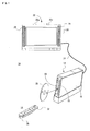
- the game apparatus 12 includes a substantially rectangular parallelepiped housing 16. On the front of the housing 16 are provided a disk slot 18 and an external memory card slot cover 20. An optical disk 22 that is an example of an information storage medium storing a game program and data is inserted from the disk slot 18 and is thereby placed in a disk drive 74 ( Figure 4 ) in the housing 16. An external memory card connector 82 ( Figure 4 ) is provided inside the external memory card slot cover 20. An external memory card (not shown) is inserted into the external memory card connector 82. The external memory card is used to load and temporarily store a game program and the like read from the optical disk 22 or save game data (result data or midway data) of a game played using the game system 10. The game data may be saved in, for example, an internal memory such as a flash memory 64 ( Figure 4 ), instead of the external memory card.
- an internal memory such as a flash memory 64 ( Figure 4 ), instead of the external memory card.
- an AV cable connector (not shown). Using the AV cable connector, the game apparatus 12 is connected to a monitor (display) 26 through an AV cable 24.
- the monitor 26 is typically a color television receiver.
- the AV cable 24 inputs a video signal from the game apparatus 12 to a video input terminal of the color television and inputs an audio signal to an audio input terminal. Accordingly, for example, a game image of a 3D video game is displayed on a screen of the color television (monitor) 26 and stereo game audio such as a game music and sound effects is outputted from built-in speakers 28.
- a marker section 30 including two infrared LEDs (markers) 30a and 30b is provided on the periphery of the monitor 26 (on the top of the monitor 26 in the present embodiment).
- the marker section 30 is connected to the game apparatus 12 through a power supply cable (not shown). Hence, power is supplied to the marker section 30 from the game apparatus 12. In this manner, the markers 30a and 30b emit light and output infrared light toward the front of the monitor 26.
- a common AC adapter (not shown).
- the AC adapter is connected to a standard household wall socket and converts household power to a low DC voltage signal suitable for driving the game apparatus 12.
- a battery may be used as a power supply.
- the controller 14 includes, although details will be described later, a remote control 32 that can be held by one hand and a gyroscope unit 34 that is removably mounted on the remote control 32. Since the gyroscope unit 34 is physically and electrically coupled to the remote control 32, input data or operation data and angular velocity data indicating angular velocities of the remote control 32 detected by the gyroscope unit 34 are outputted from the remote control 32.
- the user to play a game (or another application), the user first turns on power to the game apparatus 12. Then, the user selects an appropriate optical disk 22 storing a video game (or another application to be executed) and loads the optical disk 22 into the disk drive 74 from the disk slot 18 of the game apparatus 12. In response thereto, the game apparatus 12 starts to execute the video game or another application based on software stored on the optical disk 22. The user operates the controller 14 to provide an input to the game apparatus 12.
- Figure 2 shows an example of the external appearance of the remote control 32.
- Figure 2(A) is a perspective view of the remote control 32 as seen from the upper rear and
- Figure 2(B) is a perspective view of the remote control 32 as seen from the lower front.
- the remote control 32 has a housing 36 formed by, for example, plastic molding.
- the housing 36 has a substantially rectangular parallelepiped shape with a front/rear direction (Z-axis direction) thereof being a longitudinal direction.
- the housing 36 as a whole, has a size allowing an adult or child to hold it with his/her one hand.
- the housing 36 has a size having substantially the same length or width of a human palm. The player can perform a game operation using the remote control 32 by pressing buttons provided thereon or changing the position or orientation of the remote control 32 itself.
- the housing 36 is provided with a plurality of operation buttons. Specifically, on the top of the housing 36 are provided a cross key 38a, a "1" button 38b, a “2" button 38c, an "A” button 38d, a "- (minus)” button 38e, a HOME button 38f, and a "+ (plus)” button or start button 38g. On the bottom of the housing 36 is formed a recessed portion and a "B" button 38h is provided on a sloping surface on the rear side of the recessed portion. These buttons (switches) 38a to 38h are assigned with appropriate functions according to a game program to be executed by the game apparatus 12.
- a power switch 38i for remotely turning on/off power to a main body of the game apparatus 12.
- the buttons (switches) provided on the remote control 32 may be collectively represented by an operation means or input means using reference numeral 38.
- the cross key 38a is a four-direction push switch and includes operation portions for four directions indicated by arrows, i.e., forward (or up), backward (or down), right, and left. By operating one of these operation portions, the moving direction of a character or object (player character or player object) that can be operated by the player can be instructed or a cursor moving direction can be instructed or simply a direction can be instructed.
- the "1" button 38b and the “2" button 38c are press-button switches. For example, they are used for a game operation such as adjusting a viewpoint position or viewpoint direction when a three-dimensional game image is displayed, i.e., the position or view angle of a virtual camera.
- the "1" button 38b and the “2" button 38c may be used when the same operations as or auxiliary operations of those of the "A" button 38d and the "B" button 38h are performed.
- the "A" button switch 38d is a press-button switch and is used to cause a player character or player object to perform an action other than a direction instruction, i.e., an action such as hitting (punching), throwing, catching (obtaining), riding, or jumping. For example, in an action game, jumping, punching, moving a weapon, and the like, can be instructed. In a role-playing game (RPG) or simulation RPG, obtaining of an item, selection and determination of a weapon or command, and the like, can be instructed. Further, the "A" button switch 38d is used, when the remote control 32 is used as a pointing device, to instruct determination of an icon or button image pointed to by a pointer (pointing image) on a game screen. For example, when an icon or button image is determined, an instruction or order (command) that is set in advance for the icon or button image can be inputted.
- a direction instruction i.e., an action such as hitting (punching), throwing, catching (obtaining), riding, or jumping.
- the "-" button 38e, the HOME button 38f, the "+” button 38g, and the power switch 38i are also press-button switches.
- the "-" button 38e is used to select a game mode.
- the HOME button 38f is used to display a game menu (menu screen).
- the "+” button 38g is used, for example, to start (resume) or pause a game.
- the power switch 38i is used to remotely turn on/off power to the game apparatus 12.
- a power switch for turning on/off the remote control 32 itself is not provided and the remote control 32 is turned on by operating any of the operation means or input means 38 of the remote control 32 and is automatically turned off if there is no operation for a certain period of time (e.g., 30 seconds) or more.
- the "B” button 38h is also a press-button switch and is mainly used to perform an input imitating a trigger, such as shooting a bullet, or specify a position selected by the remote control 32.
- a trigger such as shooting a bullet
- the "B” button 38h When the "B” button 38h is kept pressed, the action or parameter of a player object can be maintained at a certain state.
- the "B" button 38h functions in the same manner as the normal “B” button and is used, for example, to cancel an action, command, and the like, determined by the "A" button 38d.
- an acceleration sensor 84 ( Figure 5 ) that detects accelerations in three-axis (X, Y, and Z) directions (i.e., a left-right direction, an up-down direction, and a forward-backward direction) shown in Figure 2 .
- X, Y, and Z three-axis
- a two-axis acceleration sensor that detects accelerations in any two of the up-down direction, the left-right direction, and the forward-backward direction may be used according to, e.g., the shape of the housing 36 or the limitations on how the remote control 32 is held.
- a single-axis acceleration sensor may be used.
- a light entrance 36b is formed at the front of the housing 36.
- An imaging information computing section 40 is further provided in the housing 36.
- the imaging information computing section 40 includes a camera that images infrared rays and a computing section that calculates coordinates, in an image, of an imaging target.
- the imaging information computing section 40 captures a field including the markers 30a and 30b by infrared rays to calculate position coordinates, in the field, of the markers 30a and 30b.
- a connector 42 is provided at the rear of the housing 36.
- the connector 42 is used to connect another device to the remote control 32.
- a connector 50 of the gyroscope unit 34 ( Figure 3(A) ) is connected to the connector 42.
- a pair of holes 44 at locations facing each other laterally (X-axis direction) with the connector 42 being sandwiched therebetween.
- Hooks 52 ( Figure 3(A) ) for fixing the gyroscope unit 34 to the rear of the housing 36 are inserted into the pair of holes 44.
- a hole 46 for attaching a strap (not shown).
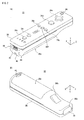
- Figure 3 shows an example of the external appearance of the gyroscope unit 34.
- Figure 3(A) is a perspective view of the gyroscope unit 34 as seen from the upper front and Figure 3(B) is a perspective view of the gyroscope unit 34 as seen from the lower rear.
- the gyroscope unit 34 has a housing 48 formed by, for example, plastic molding.
- the housing 48 has a substantially rectangular parallelepiped shape.
- the length of the housing 48 is about 1/5 of the length of the housing 36 of the remote control 32 and the width and thickness of the housing 48 are substantially the same as those of the housing 36.
- the player can perform a game operation by changing the position or orientation of the remote control 32 itself with the gyroscope unit 34 being mounted on the remote control 32.
- a connector 50 At the front of the housing 48 is provided a connector 50.
- the connector 50 is engaged with the connector 42 ( Figure 2 ) to integrally mount the housing 48, i.e., the gyroscope unit 34, on the remote control 32.
- a pair of hooks 52 at locations facing each other laterally (X-axis direction) with the connector 50 being sandwiched therebetween.
- a connector 54 for mechanically and electrically mounting another expansion device on the gyroscope unit 34.
- the housing 48 of the gyroscope unit 34 includes therein a gyroscope 56 and a microcomputer 58 shown in Figure 5 that are mounted on a substrate (not shown).
- the gyroscope 56 generally has a two-chip configuration in which one chip detects two-axis angular velocities and the other chip detects a remaining one-axis angular velocity. Note, however, that the configuration is not limited to a two-chip configuration and the gyroscope 56 may include three single-axis gyroscopes (three chips) or one three-axis gyroscope (one chip).
- each chip is determined such that the above-described three angular velocities can be correctly detected.
- the microcomputer 58 converts, as will be described later, output voltages according to respective axis angular velocities detected by the gyroscope 56 into digital data.
- Power is provided to the controller 14 by batteries (provided beneath a cover 36a at the bottom of the housing 36 shown in Figure 2 ) replaceably contained in the remote control 32. Power is supplied to the gyroscope unit 34 through the connectors 42 and 50.
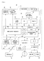
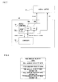
- FIG 4 is a block diagram showing an electrical configuration of the game system 10 according to the embodiment in Figure 1 .
- each component in the housing 16 is mounted on a printed board.
- the game apparatus 12 is provided with a CPU 60 that functions as a game processor.
- a system LSI 62 To the CPU 60 is connected a system LSI 62.
- an external main memory 66 To the system LSI 62 are connected an external main memory 66, a ROM/RTC 68, a disk drive 74, and an AV IC 76.
- the external main memory 66 stores programs such as a game program and various data and is used as a work area or buffer area of the CPU 60.
- the ROM/RTC 68 is a so-called boot ROM.
- a startup program of the game apparatus 12 is installed in the ROM/RTC 68 and a clock circuit that counts time is provided to the ROM/RTC 68.
- the disk drive 74 reads a program, image data, audio data, and the like, from an optical disk 22 and writes, under control of the CPU 60, the read program, data, and the like, into an internal main memory 62e, as will be described later, or the external main memory 66.
- the system LSI 62 is provided with an input/output processor 62a, a GPU (Graphics Processing Unit) 62b, a DSP (Digital Signal Processor) 62c, a VRAM 62d, and an internal main memory 62e. They are, although not shown, connected to each other via an internal bus.
- the input/output processor (I/O processor) 62a performs data transmission and reception and downloading of data. The data transmission and reception and downloading of data will be described later.
- the GPU 62b forms part of a rendering means and receives a graphics command (image generation order) from the CPU 60 and generates game image data according to the command. Note that the CPU 60 provides, in addition to the graphics command, an image generation program required to generate game image data, to the GPU 62b.
- the VRAM 62d is connected to the GPU 62b.
- Data image data: data such as polygon data and texture data
- the CPU 60 writes image data required for rendering into the VRAM 62d through the GPU 62b.
- the GPU 62b accesses the VRAM 62d to generate game image data for rendering.
- the DSP 62c functions as an audio processor and generates audio data corresponding to sound, audio, or music to be outputted from the speakers 28, using sound data or sound wave (timbre) data stored in the internal main memory 62e or the external main memory 66.
- the game image data and audio data generated in the above-described manner are read by the AV IC 76 and outputted to the monitor 26 and the speakers 28 through an AV connector 78. Accordingly, a game screen is displayed on the monitor 26 and sound (music) necessary for a game is outputted from the speakers 28.
- a flash memory 64 To the input/output processor 62a are connected a flash memory 64, a wireless communication module 70, and a wireless controller module 72 and are also connected an expansion connector 80 and an external memory card connector 82.
- a wireless communication module 70 To the wireless communication module 70 is connected an antenna 70a.
- an antenna 72a To the wireless controller module 72 is connected an antenna 72a.
- the input/output processor 62a can communicate with other game apparatuses and various servers connected to a network, through the wireless communication module 70. Note that communication with other game apparatuses can also be directly performed instead of through a network.
- the input/output processor 62a periodically accesses the flash memory 64 to detect whether there is data (referred to as "transmit data") that needs to be transmitted to the network. If there is transmit data, then the input/output processor 62a transmits the transmit data to the network through the wireless communication module 70 and the antenna 70a.
- the input/output processor 62a receives data (referred to as “receive data”) transmitted from other game apparatuses, through the network, the antenna 70a, and the wireless communication module 70 and stores the receive data in the flash memory 64. Note, however, that when receive data does not satisfy a certain condition, the receive data is discarded.
- the input/output processor 62a further receives data (referred to as "downloaded data") downloaded from a download server, through the network, the antenna 70a, and the wireless communication module 70 and stores the downloaded data in the flash memory 64.
- the input/output processor 62a receives input data transmitted from the remote control 32, through the antenna 72a and the wireless controller module 72 and (temporarily) stores the input data in a buffer area of the internal main memory 62e or the external main memory 66.
- the input data is used in processing (e.g., game processing) of the CPU 60 and is thereafter deleted from the buffer area.
- the wireless controller module 72 performs communication with the remote control 32 according to the Bluetooth standard. Hence, not only is obtained data from the controller 14 but also a predetermined order can be sent to the controller 14 from the game apparatus 12 to control the operation of the controller 14 from the game apparatus 12.
- the expansion connector 80 is a connector for an interface such as a USB or SCSI and can connect to a medium such as an external storage medium or connect to a peripheral device other than the remote control 32, such as a controller. Also, by connecting a wired LAN adapter to the expansion connector 80, the wired LAN can be used instead of the wireless communication module 70.
- the external memory card connector 82 can be connected an external storage medium such as a memory card.
- the input/output processor 62a can access an external storage medium through the expansion connector 80 or the external memory card connector 82 to save data or read data.
- the system LSI 62 instructs those components other than the input/output processor 62a, the flash memory 64, the external main memory 66, the ROM/RTC 68, the wireless communication module 70, and the wireless controller module 72 to stop power supply.
- the CPU 60 does not execute any application.
- a fan to discharge heat from ICs such as the CPU 60 and the system LSI 62 to the outside. In the standby mode, the fan is also stopped.
- Switching between the normal mode and the standby mode can be remotely performed by switching on and off the power switch 38i of the remote control 32.
- a setting may be made not to supply power to the wireless controller module 72 in the standby mode.
- a reset button is also connected to the system LSI 62. When the reset button is pressed, the system LSI 62 restarts a startup program of the game apparatus 12.
- An eject button is connected to the disk drive 74. When the eject button is pressed, the optical disk 22 is ejected from the disk drive 74.
- FIG. 5 shows an example of an overall electrical configuration of the controller 14 when the remote control 32 is connected to the gyroscope unit 34.
- a communication section 86 shown in Figure 5 includes a microcomputer 88, a memory 90, a wireless module 92, and an antenna 94.
- the microcomputer 88 controls the wireless module 92 while using, upon processing, the memory 90 as a memory area (work area or buffer area), to transmit obtained data to the game apparatus 12 or receive data from the game apparatus 12.
- Data outputted to the communication section 86 from the gyroscope unit 34 is temporarily stored in the memory 90 through the microcomputer 88.
- Data outputted to the communication section 86 from the operation section 38, the imaging information computing section 40, and the acceleration sensor 84 in the remote control 32 is also temporarily stored in the memory 90.
- the microcomputer 88 When transmission timing to the game apparatus 12 arrives, the microcomputer 88 outputs data stored in the memory 90 to the wireless module 92 as controller data.
- the controller data includes gyro data (angular velocity data) shown in Figure 10 .
- the wireless module 92 modulates a carrier wave having a predetermined frequency by the controller data, using a short-range wireless communication technique such as Bluetooth and radiates a resulting weak radio signal from the antenna 94. That is, the controller data is modulated into a weak radio signal by the wireless module 92 and the weak radio signal is transmitted from the remote control 32.
- the weak radio signal is received by the wireless controller module (Bluetooth communication unit) 72 on the side of the game apparatus 12.
- the game apparatus 12 can obtain the controller data.
- the CPU 60 of the game apparatus 12 performs game processing based on the controller data obtained from the controller 14. Note that wireless communication between the remote control 32 and the game apparatus 12 may be performed according to other standards such as a wireless LAN standard.
- the operation section 38 i.e., the aforementioned operation buttons or operation switches 38a to 38i
- data representing the operation is outputted to the communication section 86.
- the imaging information computing section 40 is outputted data indicating position coordinates, in the captured field, of the markers 30a and 30b to the communication section 86.
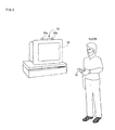
- Figure 6 is an illustrative view outlining a state when a game is played using the remote control 32. Note, however, that this is not limited to game play and the case in which other applications are executed or a DVD is played back is also the same.
- a game is played using the remote control 32 in the game system 10
- a player holds the remote control 32 with his one hand. Strictly, the player holds the remote control 32 such that a tip of the remote control 32 (the side of the light entrance 36b of light imaged by the imaging information computing section 40) is pointed toward the markers 30a and 30b.
- the markers 30a and 30b are disposed parallel to a lateral direction of a screen of the monitor 26. In this state, the player performs a game operation by changing the position on the screen pointed to by the remote control 32 or changing the distance between the remote control 32 and each of the markers 30a and 30b.
- the imaging information computing section 40 includes an infrared filter 40a, a lens 40b, an imaging element 40c, and an image processing circuit 40d.
- the infrared filter 40a allows only infrared rays among lights entering from the front of the remote control 32 to pass therethrough.
- the markers 30a and 30b disposed near (on the periphery of) the display screen of the monitor 26 are infrared LEDs that output infrared rays toward the front of the monitor 26. Therefore, by providing the infrared filter 40a, images of the markers 30a and 30b can be imaged more accurately.
- the lens 40b collects infrared rays having passed through the infrared filter 40a and emits the collected infrared rays to the imaging element 40c.
- the imaging element 40c is a solid-state imaging element, such as a CMOS sensor or CCD, and images the infrared rays collected by the lens 40b. Thus, the imaging element 40c images only those infrared rays that have passed through the infrared filter 40a to generate image data.
- the image data generated by the imaging element 40c is processed by the image processing circuit 40d.
- the image processing circuit 40d calculates positions of imaging targets (markers 30a and 30b) in an imaged image and outputs, as marker coordinate data, coordinate values indicating the positions to the microcomputer 88 at predetermined time intervals.
- marker coordinates are represented by integer values between (0,0) and (1024, 768).
- Outputted marker coordinate data is, as described above, included in input data by the microcomputer 88 and transmitted to the game apparatus 12.
- the game apparatus 12 When the game apparatus 12 (CPU 60) detects marker coordinate data from received input data, the game apparatus 12 (CPU 60) can calculate, based on the marker coordinate data, a pointing position (pointing coordinates) of the remote control 32 on a screen of the monitor 26 and distances between the remote control 32 and the markers 30a and 30b. Specifically, a position to which the remote control 32 is pointed, i.e., a pointing position, is calculated from the position of a midpoint between the two sets of marker coordinates.
- the game apparatus 12 can grasp distances between the remote control 32 and the markers 30a and 30b.
- the acceleration sensor 84 has a sampling period of, for example, the order of 100 frames/second at the maximum.
- the gyroscope unit 34 includes therein a gyroscope 56 and a microcomputer 58.
- the gyroscope 56 has, for example, the same sampling period as the acceleration sensor 84.
- the microcomputer 58 outputs data indicating angular velocities detected by the gyroscope 56 to the communication section 86 through the connector 50 and the connector 42.
- Figure 7 shows a configuration of a main part of the gyroscope unit 34 in the overall configuration shown in Figure 5 .
- the connector 42 and the connector 50 each are, for example, a 6-pin connector.
- the 6 pins include an Attach pin for controlling the variable "Attach" indicating the connection state between the connectors.
- the Attach changes between "Low” indicating that the connector 42 and the connector 50, i.e., the remote control 32 and the gyroscope unit 34, are disconnected from each other and "High” indicating that the connector 42 and the connector 50, i.e., the remote control 32 and the gyroscope unit 34, are connected to each other.
- two pins are assigned with an I2C bus and output data (angular velocity data) from the gyroscope unit 34 shown in Figure 8 is inputted to the remote control 32 through the I2C bus.
- the microcomputer 58 of the gyroscope unit 34 includes A/D conversion circuits 58a and 58b. Angular velocity signals about three axes to be outputted from the gyroscope 56 are provided to each of the A/D conversion circuits 58a and 58b.
- the A/D conversion circuit 58a performs an A/D conversion process in a high angular velocity mode that targets all of a detection range of the gyroscope 56 (e.g., ⁇ 360 degrees/second).
- the A/D conversion circuit 58b performs an A/D conversion process in a low angular velocity mode that targets part of the detection range of the gyroscope 56 (e.g., ⁇ 90 degrees/second).
- the microcomputer 58 outputs one of the two types of A/D conversion results as angular velocity data.
- the microcomputer 58 first determines for each axis, i.e., each of yaw, roll, and pitch, whether a value A of one of the angular velocity data that is angular velocity data in the low angular velocity mode is within a range from a first threshold value Th1 to a second threshold value Th2 (> Th1), i.e., whether the condition "Th1 ⁇ A ⁇ Th2" is satisfied. Then, based on the three determination results, one of the low angular velocity mode and the high angular velocity mode is selected.
- the angular velocity data units according to their respective modes selected for each axis are each outputted together with mode information indicating the selected mode.
- mode information indicating the selected mode.
- Figure 8 shows a format of data handled by the gyroscope unit 34.
- Data for the gyroscope unit 34 includes yaw angular velocity data, roll angular velocity data, pitch angular velocity data, yaw angular velocity mode information, roll angular velocity mode information, and pitch angular velocity mode information.
- a y-axis rotation is represented by a yaw angle
- an x-axis rotation is represented by a pitch angle
- a z-axis rotation is represented by a roll angle.
- Each of the yaw angular velocity data, the roll angular velocity data, and the pitch angular velocity data is, for example, 14-bit data obtained by A/D converting a corresponding one of a yaw angular velocity signal, a roll angular velocity signal, and a pitch angular velocity signal outputted from the gyroscope 56.
- Each of the yaw angular velocity mode information, the roll angular velocity mode information, and the pitch angular velocity mode information is one-bit information indicating a mode of corresponding angular velocity data, and changes between "0" corresponding to the high angular velocity mode and "1" corresponding to the low angular velocity mode.
- the gyroscope unit 34 outputs gyro data according to the format shown in Figure 8 to the communication section 86 in, for example, a 1/100 second period. This is sufficiently shorter than a 1/60 second period that is a general processing period for game processing and the like, and thus the data can be fully used in game processing.
- Gyro data such as that shown in Figure 8 is transmitted from the remote control 32 to the game apparatus 12 as angular velocity data "data", as will be described later.
- an input to an application such as a game can be performed not only by a button operation but also by moving the controller 14 itself.
- the acceleration sensor 84 that detects accelerations in three-axis directions is built in the remote control 32 and when the gyroscope unit 34 is mounted on the remote control 32, angular velocities about three axes indicating a movement of the remote control 32 itself are further detected.
- the controller data from the controller 14 is received by the input/output processor 62a through the antenna 72a and the wireless controller module 72 and the received controller data is written into a buffer area of the internal main memory 62e or the external main memory 66.
- the CPU 44 reads the controller data stored in the buffer area of the internal main memory 62e or the external main memory 66 and reconstructs the detected values, i.e., the values of accelerations and/or angular velocities detected by the controller 14, from the controller data.
- angular velocity data has two modes, i.e., high angular velocity and low angular velocity modes
- two types of angular velocity reconstruction algorithms respectively for the two modes are prepared.
- an angular velocity reconstruction algorithm appropriate for the mode of the angular velocity data is selected based on angular velocity mode information.
- the CPU 60 may perform, in parallel with such a reconstruction process, a process of computing a velocity of the controller 14 from reconstructed accelerations. Furthermore, in parallel with this, the moving distance or position of the controller 14 can also be obtained from the computed velocity. On the other hand, from reconstructed angular velocities, a rotation angle of the controller 14 can be obtained. Note that an initial value (integral constant) used when a velocity is obtained by adding up accelerations or a rotation angle is obtained by adding up angular velocities may be computed based on, for example, position coordinate data from the imaging information computing section 40. The position coordinate data may also be used to modify error accumulated by adding up.
- Game processing is performed based on variables obtained in the above-described manner, such as accelerations, a velocity, a moving distance, angular velocities, and a rotation angle. Therefore, it is not necessary to perform all of the above-described processes and only those variables that are required for game processing are appropriately calculated.
- angular velocities and a rotation angle can also be computed from accelerations in principle but doing so requires a complex routine for a game program, imposing a heavy processing load on the CPU 60.
- program development is facilitated and also the processing load of the CPU 60 is reduced.
- Figure 10 is an illustrative view showing a memory map of the internal main memory 62e or the external main memory 66 shown in Figure 4 .
- the main memory (62e or 66) includes a program memory area 96 and a data memory area 98. Note that specific contents of the data memory area 98 are shown in Figure 11 .
- the program memory area 96 stores a game program and the game program includes a game main processing program 96a, an image generation program 96b, an image display program 96c, an angular velocity detection program 96d, an acceleration detection program 96e, and the like.
- the game main processing program 96a is a program for processing a main routine of a virtual game according to the present embodiment.
- the image generation program 96b is a program for generating a game image to display a game screen on the monitor 26, using image data 98a (see Figure 11 ), as will be described later.
- the image display program 96c is a program for displaying the game image generated according to the image generation program 96b, on the monitor 26 as a game screen.
- the angular velocity detection program 96d is a program for detecting angular velocity data concerning angular velocities detected by the gyroscope 56. Since, as described above, angular velocity data is included in input data from the remote control 32, the CPU 60 detects angular velocity data included in input data from the remote control 32, according to the angular velocity detection program 96d. Note that the angular velocity detection program 96d includes a correction program shown in Figure 14 , as will be described later.
- the acceleration detection program 96e is a program for detecting acceleration data concerning accelerations detected by the acceleration sensor 84. Since, as described above, acceleration data is included in input data from the remote control 32, the CPU 60 detects one or two acceleration data units included in input data from the remote control 32, according to the acceleration detection program 96e.
- the game program also includes a sound output program, a backup program, and the like.
- the sound output program is a program for outputting, using sound (music) data, sound required for a game, such as music (background music), voice or onomatopoeic sound of an object, and sound effects.
- the backup program is a program for saving game data (midway data and result data) in a memory card.
- the data memory area 98 temporarily stores various data such as image data 98a, angular velocity data 98b, and acceleration data 98c. Also, in the data memory area 98, a flag register area 98d for a timer, a register, and further a necessary flag, a FIFO (First-In First-Out) buffer 100, and the like, are appropriately provided.
- a flag register area 98d for a timer, a register, and further a necessary flag a FIFO (First-In First-Out) buffer 100, and the like.
- the image data 98a is image data for generating a game image and includes object image data of a player object, a non-player object, and the like, and further includes polygon data, texture data, and the like.
- the angular velocity data 98b is angular velocity data obtained through detection according to the angular velocity detection program 96d and correction according to the correction program. Note that in the present embodiment three or four angular velocity data units are detected for each frame.
- the acceleration data 98c is acceleration data of the remote control 32 detected according to the acceleration detection program 96e.
- angular velocity and acceleration data are used to calculate a posture for each frame, such a number of (e.g., 20) angular velocity and acceleration data that corresponds to a plurality of frame periods may be stored for the purpose of, e.g., correction.
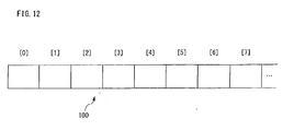
- the FIFO buffer 100 includes a plurality of stages of data buffers connected in series and each stage (memory location) is specified by a buffer index idx.
- the data buffers are stored digital data such as angular velocity data and acceleration data.
- a modification offset value ofs set in the flag register area 98d in the data memory area 98 shown in Figure 11 is initialized.
- the modification offset value ofs is an offset value (zero-point offset value) used for correction to eliminate (reduce) a difference occurred, due to a temperature drift and the like, between digital integer value data associated with an analog value indicating that an angular velocity outputted from the gyroscope 56 is zero and digital integer value data obtained by converting an analog value actually indicating that the velocity is zero.
- An initial value (device's unique value) stored upon the initialization is, for example, unique to each individual gyroscope 56 included in the gyroscope unit 34 and is set at factory shipment of the gyroscope 56.
- Each individual sets an initial value unique to a device thereof, as a modification offset value ofs.
- a value measured at 25°C at the factory is an initial value.
- the value may be renewable by a predetermined method after factory shipment.
- the CPU 60 initializes a buffer index idx for specifying a data buffer of the FIFO buffer 100.
- a buffer index idx for specifying a data buffer of the FIFO buffer 100.
- "0" is set for the buffer index idx.
- the initial value may be any value in a range from “0" to "BUFS-1".
- the "BUFS” refers to a numerical value indicating the size of the FIFO buffer 100 and is stored, for example, in the flag register area 98d as a buffer capacity BUFS.
- the initial value of the buffer index idx is set in a range from "0" to "399 (400-1)".
- a value such as "-100” is set that is sufficiently far from a value obtained by subtracting a constant C1 (e.g., "1") from a range of values obtained from the gyroscope 56 (buf [0 - (BUFS - 1)] ⁇ -100).
- angular velocity data is obtained according to an angular velocity data obtaining process shown in Figure 14 .
- the CPU 60 determines whether it is a scene where there is a possibility of performing an operation of moving the remote control 32, i.e., the gyroscope unit 34, with constant velocity. For example, in a shooting game, when a target is aimed with a gun loaded with bullets or a bow fixed with an arrow, the player performs an operation of slowly moving the muzzle of the gun or the arrow, for example, from the left to the right. When performing an operation of aiming with the muzzle of the gun or the arrow using the remote control 32, the remote control 32 is slowly moved in the real space.
- the remote control 32 is slowly moved in the real space.
- the remote control 32 i.e., the gyroscope unit 34
- the remote control 32 is operated with a constant velocity in the real space.
- the CPU 60 sets, in a step S13, an offset correction flag cfg to 0 and proceeds to a step S15. If “NO” in the step S11, then the CPU 60 sets, in a step S 14, the offset correction flag cfg to 1 and proceeds to the step S 15.
- the offset correction flag cfg is a flag indicating whether the modification offset value ofs needs to be corrected. When the modification offset value ofs need not be corrected (when there is a possibility of performing a constant velocity operation), 0 is set, and when the modification offset value ofs needs to be corrected (when there is no possibility of performing a constant velocity operation), is set.
- step S15 it is determined whether the game is ended. For example, when “game over” is reached or the player operates the remote control 32 to end the game, the step S 15 is "YES” and the game is ended. If “NO” in the step S 15, then processing returns to the previous step S7 to continuously perform obtaining of angular velocity data, game processing, and the like.
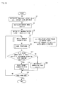
- a first step S31 in Figure 14 the CPU 60 increments the buffer index idx (idx ⁇ (idx + 1)%BUFS) where the symbol "%" represents an operator indicating a remainder and modulo arithmetic is performed. For example, when the process is performed with the FIFO buffer 100 of a size whose buffer capacity BUFS is set as "400", the buffer index idx is updated (incremented) by 1 in the range from “0" to "399". Note, however, that by performing modulo arithmetic, "399" is updated to "0".
- the reason why the buffer index idx is thus updated using a remainder is that an update process of the buffer index idx is efficiently performed that is performed to systematically and efficiently use a plurality of stages of data buffers connected in series and included in the FIFO buffer 100 that is a loop buffer whose capacity is predetermined.
- a next step S33 the CPU 60 obtains angular velocity data (integer value) from the controller 14, i.e., the remote control 32, received by the input/output processor 62a and stores the obtained angular velocity data in the angular velocity data "data" included in the flag register area 98d ( Figure 11 ).
- the CPU 60 stores the angular velocity data (the latest angular velocity data) stored in the angular velocity data "data" in a data buffer of the FIFO buffer 100 indicated by the buffer index idx incremented in the step S31 (buf[idx] ⁇ data).
- a next step S37 the CPU 60 prepares to check past data. Specifically, in the present embodiment, in the step S37, preparation (initialization or setting of variables and counters) is performed for a comparison process between the angular velocity data (the latest angular velocity data) stored in the angular velocity data "data" and past angular velocity data (angular velocity data stored in data buffers of the FIFO buffer 100). The comparison process is performed to correct the angular velocity data obtained from the controller 14, i.e., the remote control 32, and correct a deviation of the modification offset value ofs of the gyroscope 56.
- the CPU 60 first sets a number of consecutive units ct formed in the flag register area 98d to "1".
- the number of consecutive units ct is a counter for counting the number of consecutive units and a value indicated by the number of consecutive units ct indicates how many times a data buffer having a value that satisfies a certain condition (described later) (step S39) is consecutively detected.
- a sum value sum similarly formed in the flag register area 98d is stored the angular velocity data written into the angular velocity data "data" in the step S33. That is, the angular velocity data written, as an initial state, into the angular velocity data "data” in the step S33 is stored in the sum value sum.
- a stable range (lower limit) d1 and a stable range (upper limit) d2 are set.
- the stable range (lower limit) d1 is set to a lower limit value data-C1 and the stable range (upper limit) d2 is set to an upper limit value data + C1.
- a lower limit value and an upper limit value respectively set for the stable range (lower limit) d1 and the stable range (upper limit) d2 a range with equal upper and lower bounds with the angular velocity data "data" written in the previous step S33 being the center (with upper and lower widths each corresponding to C1) is set.
- the constant C1 may be a variable and may be changed according to angular velocity data "data", the number of consecutive units ct, and the like, or may be changed depending on other circumstances.
- a variable i in the step S37 is a value for specifying a location of a data buffer that is checked retrogressively from the data buffer of the FIFO buffer 100 indicated by the buffer index idx, into which data buffer the angular velocity data is written in the step S35, and is set in the flag register area 98d. Then, the variable i is shifted in a direction in which the variable i is decremented by "1" ((idx - 1 + BUFS)%BUFS) to check a value in a data buffer specified by the variable. When the variable i reaches a variable i2, the retrogressive search is ended.
- variable i and the variable i2 are thus set using a remainder is the same as that for using a remainder when the buffer index idx is updated.
- the reason why the buffer capacity BUFS is added (+ BUFS) when the variable i is set is that, when the buffer index idx is 0, "idx - 1" becomes negative (-), and if modulo arithmetic is performed on a negative value, a correct computation result cannot be obtained.
- a comparison process is performed between the angular velocity data (the latest angular velocity data) stored in the angular velocity data "data” and past angular velocity data (angular velocity data stored in data buffers of the FIFO buffer 100).
- the CPU 60 determines whether a value in a data buffer specified by the variable i incremented in the step S37 is within the stable range set by the stable range (lower limit) d1 and the stable range (upper limit) d2 (d1 ⁇ buf[i] ⁇ d2).
- step S39 i.e., if the value in the data buffer specified by the variable i is included in the stable range set by the stable range (lower limit) d1 and the stable range (upper limit) d2 (the value is close to the angular velocity data "data")
- the value included in the stable range i.e., the value in the data buffer specified by the variable i
- the sum value is updated using the value in the data buffer.
- a step S43 the number of consecutive units ct is incremented. In this manner, the number of data buffers consecutively satisfying the stable range condition is counted by the number of consecutive units ct. Furthermore, in the step S43, the variable i is shifted in the direction in which the variable i is decremented by "1" and is thereby updated (I ⁇ (i - 1 + BUFS)%BUFS). The reason why the buffer capacity BUFS is added (+ BUFS) when the variable i is updated is the same as that for setting the variable i in the step S37. Then, in a step S45, it is determined whether a number of searches corresponding to the maximum number of searches CMAX have been performed.
- variable i is updated and it is determined whether the variable i has reached the variable i2. If a number of searches corresponding to the maximum number of searches CMAX have been performed, then it is "YES” and processing proceeds to a step S47. On the other hand, if a number of searches corresponding to the maximum number of searches CMAX have not been performed, then it is "NO" and in that case processing returns to the previous step S39 to continue a search.
- step S39 it indicates that a value outside the stable range set by the stable range (lower limit) d1 and the stable range (upper limit) d2 is detected in a data buffer before a number of searches corresponding to the maximum number of searches CMAX are performed, which in other words indicates that a movement with a large velocity change is provided to the remote control 32, i.e., the gyroscope unit 34 (abruptly moved).
- processing proceeds from the step S39 to the step S47.
- data buffers consecutively included in the stable range (d1 ⁇ buf[i] ⁇ d2) retrogressively from the location of the data buffer into which the angular velocity data is written in the step S35 in order from newest to oldest data buffers are repeatedly obtained and a number of the data buffers (the number of consecutive units ct) and a sum value (sum value sum) are calculated (note that the upper limit number of searches is the maximum number of searches CMAX).
- step S47 the CPU 60 obtains a stationary degree value (stationary level) "a" of the remote control 32, i.e., the gyroscope unit 34, at that time.
- the CPU 60 corrects the angular velocity data "data” using an average value according to the stationary degree value "a" (data ⁇ data + (sum ⁇ ct - data) x a). Specifically, the sum value stored in the sum value sum is divided by the number of consecutive units ct, the angular velocity data "data” is subtracted from the resulting quotient, the resultant is multiplied by the stationary degree value "a”, and the resultant is added to the angular velocity data "data”, which in other words, indicates that weighting as to whether the angular velocity data "data” is adopted or the average value (sum ⁇ ct) is adopted is determined according to the value of the stationary degree value "a".
- a weighted average value of the average value and the angular velocity data "data” is calculated such that the larger the stationary degree value "a” the heavier the weight of the average value (the greater the influence of the average value). Also, a weighted average value of the average value and the angular velocity data “data” is calculated such that the smaller the stationary degree value "a” the heavier the weight of the angular velocity data “data” (the greater the influence of the angular velocity data “data”). By the calculated weighted average value, the angular velocity data "data” is corrected.
- the angular velocity data "data” may be left as it is without being updated and corrected data may be separately outputted.
- the angular velocity data "data” that is corrected in the step S49 may be separately outputted.
- the angular velocity data "data” can be used for another purpose.
- step S49 weighting is performed using the stationary degree value "a"
- the stationary degree value "a” since only those data buffers that are determined in the step S39 to be consecutively included in the stable range set by the stable range (lower limit) d1 and the stable range (upper limit) d2 retrogressively from the data buffer having stored therein the angular velocity data "data” influence the number of consecutive units ct and the sum value sum and data obtained when a movement with a large change is performed is less likely to exert an influence, by setting the stationary degree value "a” to 1 at all times, i.e., by substituting an average value (sum ⁇ ct) into the angular velocity data "data”, the angular velocity data "data” may be corrected.
- a predetermined threshold value may be provided to the stationary degree value "a” and only when the stationary degree value "a” exceeds the predetermined threshold value, a correction in the step S49 may be made, or on the contrary, only when the stationary degree value "a” falls below the predetermined threshold value, a correction in the step S49 may be made.
- the angular velocity data "data” is adopted with a heavy weight (the influence of the angular velocity data “data” is great) and thus, for example, when an abrupt change is occurring, the angular velocity data "data” is corrected so as to promptly reflect the change and thus angular velocity data "data” with high trackability (excellent response) that promptly reflects a movement with a large change is obtained.
- a step S51 it is determined whether the modification offset value ofs is to be corrected. Specifically, the determination is made based on the offset correction flag cfg that is set (reset) in the step S 13 or S 14 in Figure 13 based on the result of the determination in the step S11 in Figure 13 made during game processing as to whether it is a scene where there is a possibility of performing an operation of moving the remote control 32, i.e., the gyroscope unit 34, with a constant velocity.
- step S 11 in Figure 13 branches to "YES" and the offset correction flag cfg is set to 0 in the step S 13 and thus there is a possibility of performing an operation of moving the remote control 32, i.e., the gyroscope unit 34, with a constant velocity, without correcting the modification offset value ofs, processing proceeds to a step S55.
- a level of a correction made such that the angular velocity data "data" corrected in the step S49 is angular velocity data (zero point) for a controller's stationary state is calculated according to the magnitude of the stationary degree value "a” and the offset value (modification offset value ofs) is corrected according to the level.
- the stationary degree value "a” is changed.
- the constant C2 is set, for example, to "0.01” and the stationary degree value "a” is changed to 0.01 x a.
- the reason why the stationary degree value "a” is changed to a smaller value by multiplying the stationary degree value "a” by the constant C2 is that if the stationary degree value "a” calculated in the step S47 is used as it is, the angular velocity data "data” is corrected in a short period of time to angular velocity data (zero point) for a controller's stationary state, making it difficult to obtain a value of the angular velocity data "data".
- the phenomenon "temperature drift” that causes a zero-point deviation is not a phenomenon with a rapid change and thus this correction need not be made with fast response.
- the constant C2 may be a variable and may be changed according to angular velocity data "data”, the number of consecutive units ct, and the like, or may be changed depending on other circumstances. Then, by using the changed stationary degree value "a", the modification offset value ofs is corrected. Specifically, a result obtained by subtracting the modification offset value ofs from the angular velocity data "data” corrected in the step S49 is multiplied by the stationary degree value "a” changed by being multiplied by the constant C2 and a resulting value is added to the modification offset value ofs.
- the rate (level) at which the modification offset value ofs converges to the angular velocity data "data" corrected in the step S49 increases.
- the modification offset value ofs may be corrected only when a predetermined condition is satisfied (e.g., when a result obtained by subtracting the modification offset value ofs from the angular velocity data "data" is less than or equal to a predetermined value).
- a step S55 taking into account a zero-point correction for an angular velocity outputted from the gyroscope 56, by subtracting the modification offset value ofs from the angular velocity data "data” corrected in the step S49, the angular velocity data "data” is corrected again and processing returns to the step S9 in Figure 13 .
- the step S11 in Figure 13 branches to "YES” and the offset correction flag cfg is set to 0 in the step S13 and thus there is a possibility of performing an operation of moving the remote control 32, i.e., the gyroscope unit 34, with a constant velocity
- the angular velocity data "data” is corrected using the modification offset value ofs that is not corrected in the step S53.
- a determination as to whether the remote control 32, i.e., the gyroscope unit 34, such as those in the embodiment, is stable is made according to the magnitude of the stationary degree value "a" (the length of the period during which a change in the movement of the remote control 32, i.e., the gyroscope unit 34, is small (stable)), when the remote control 32, i.e., the gyroscope unit 34, is made to continuously move with constant velocity, too, a phenomenon occurs that it is determined that the stationary degree value (stationary level) "a" is large (the period during which a change in the movement of the remote control 32, i.e., the gyroscope unit 34, is small (stable) is long).
- the rate (level) at which the modification offset value ofs is corrected to a value close to the angular velocity data "data" corrected in the step S49 increases, and thus, there is a problem that a state in which the remote control 32, i.e., the gyroscope unit 34, is moving is corrected to angular velocity data (zero point) for a controller's stationary state.
- the remote control 32 i.e., the gyroscope 56
- the remote control 32 i.e., the gyroscope unit 34
- the remote control 32 cannot be continuously and accurately moved with constant velocity, like a machine, to the extent that a zero-point offset modification for an angular velocity takes place, and thus, there is no problem in practical use.
- a zero-point offset value can be modified such that a temperature drift can be properly compensated for but it requires cost.
- a zero-point offset value (modification offset value ofs) is corrected according to a stationary degree value (stationary level) "a"
- the zero-point offset value (modification offset value ofs) can be corrected to reduce the influence of a temperature drift.
- the present invention can be applied to any sensor that obtains digital data using such A/D conversion.
- other motion sensors such as an acceleration sensor, a velocity sensor, a displacement sensor, and a rotation angle sensor may be used.
- motion sensors there are a tilt sensor, an image sensor, an optical sensor, a pressure sensor, a magnetic sensor, a temperature sensor, and the like, and in any sensor, the present invention can be applied to any apparatus that converts a detected analog value from a sensor into digital data and uses the digital data.
- an acceleration sensor does not have an idea of zero-point offset.
- the latest digital data is "2" or "3".
- the number of consecutive values (the number of consecutive units ct) in a range set in the past by a stable range (lower limit) d1 and a stable range (upper limit) d2 is equal to the maximum number of searches CMAX "10" and a stationary degree value "a" calculated in the step S47 in Figure 14 is "1".
- a zero-point correction starts from data, seventh from left, and the correction is completed on data, twelfth from left.
- the gyroscope unit 34 (gyroscope 56) is connected to the remote control 32
- the gyroscope 56 may be built in the remote control 32.
- digital data (angular velocity data) outputted from a predetermined sensor is corrected with a stationary degree, and the like, being calculated using digital data (angular velocity data) outputted from the same sensor (gyroscope)
- a correction may be made with a stationary degree, and the like, being set using digital data outputted from a different sensor.
- digital data (angular velocity data) outputted from a gyroscope may be corrected with a stationary degree being calculated from digital data (acceleration data) outputted from an acceleration sensor.
Landscapes
- Engineering & Computer Science (AREA)
- Theoretical Computer Science (AREA)
- Physics & Mathematics (AREA)
- General Physics & Mathematics (AREA)
- Radar, Positioning & Navigation (AREA)
- Remote Sensing (AREA)
- User Interface Of Digital Computer (AREA)
- Gyroscopes (AREA)
- Indication And Recording Devices For Special Purposes And Tariff Metering Devices (AREA)
- Arrangements For Transmission Of Measured Signals (AREA)
- Navigation (AREA)
Claims (15)
- Speichermedium, das ein digitales Datenkorrektur-Programm so speichert, dass das Programm von einem Computer (10) einer digitalen Datenkorrektur-Einrichtung gelesen werden kann, die digitale Daten korrigiert, die erhalten wurden, indem durch ein A/D-Wandlungsmittel (58a, 58b) eine analoge Größe umgewandelt wird, die durch einen vorbestimmten Sensor (56) gemessen wurde, wobei das digitale Datenkorrektur-Programm den Computer veranlasst, sich zu verhalten als:Puffermittel (100) zum sequenziellen Speichern digitaler Daten, die vom A/D-Wandlungsmittel umgewandelt wurden;ein Stabiles-Bereich-Berechnungsmittel (60; S39) zum Berechnen eines stabilen Bereichs für die letzten digitalen Daten, die vom A/D-Wandlungsmittel umgewandelt wurden;ein Mittelwert-Berechnungsmittel (60; S49) zum Berechnen eines Mittelwerts derjenigen der digitalen Daten, die in dem Puffermittel gespeichert sind, die aufeinanderfolgend im stabilen Bereich rückwärtsschreitend von den letzten digitalen Daten vorhanden sind; undDatenkorrektur-Mittel (60; S49) zum Korrigieren der letzten digitalen Daten unter Verwendung des Mittelwertes, der von dem Mittelwert-Berechnungsmittel berechnet wurde.
- Speichermedium gemäß Anspruch 1, worin das digitale Datenkorrektur-Programm den Computer weiter veranlasst zu funktionieren als ein Anzahl-von-aufeinanderfolgenden-Einheiten-Berechnungsmittel zur Berechnung einer Anzahl von aufeinanderfolgenden Einheiten derjenigen digitalen Daten, die in dem Puffermittel gespeichert sind, die aufeinanderfolgend im stabilen Bereich rückwärtsschreitend von den letzten digitalen Daten vorhanden sind; und
das Datenkorrektur-Mittel ein gewichtetes-Mittelwert-Berechnungsmittel aufweist, um einen gewichteten Mittelwert der letzten digitalen Daten und des Mittelwerts basierend auf der Anzahl der aufeinanderfolgenden Einheiten zu berechnen und den gewichteten Mittelwert als korrigierte digitale Daten verwendet. - Speichermedium gemäß Anspruch 2, worin das gewichtete-Mittelwert-Berechnungsmittel ein Gewicht des Mittelwerts bildet, das schwerer wird, wenn die Anzahl der aufeinanderfolgenden Einheiten größer wird.
- Speichermedium gemäß Anspruch 3, worin das gewichtete-Mittelwert-Berechnungsmittel ein Gewicht des Mittelwerts bildet, das proportional zu einer Potenz der Anzahl von aufeinanderfolgenden Einheiten schwerer wird.
- Speichermedium gemäß Anspruch 1, worin der stabile Bereich ein Bereich ist, der die letzten digitalen Daten umfasst.
- Speichermedium gemäß Anspruch 5, worin der stabile Bereich ein Bereich ist mit gleichen oberen und unteren Grenzen, mit den letzten digitalen Daten als Zentrum.
- Speichermedium gemäß Anspruch 1, worin
das Datenkorrektur-Programm weiter den Computer veranlasst zu funktionieren als:ein Anzahl-von-aufeinanderfolgende-Einheiten-Berechnungsmittel zum Berechnen einer Anzahl von aufeinanderfolgenden Einheiten derjenigen der digitalen Daten, die im Puffermittel gespeichert sind, die aufeinanderfolgend im stabilen Bereich zurückschreitend von den letzten digitalen Daten enthalten sind;ein Modifikation-Offsetwert-Berechnungsmittel (60; S53) zum Berechnen, gemäß der Anzahl der aufeinanderfolgenden Einheiten, eines Modifikation-Offsetwerts, der auf die digitalen Daten konvergiert, die vom Datenkorrektur-Mittel korrigiert wurden; undein Offsetkorrektur-Mittel zum Korrigieren der digitalen Daten, die vom Datenkorrektur-Mittel korrigiert wurden unter Verwendung des Modifikation-Offsetwertes. - Speichermedium gemäß Anspruch 7, worin das Modifikation-Offsetwert-Berechnungsmittel einen Modifikations-Offsetwert berechnet, dessen Konvergenzgrad auf die digitalen Daten, die vom Datenkorrektur-Mittel korrigiert wurden, höher wird, wenn die Anzahl der konsekutiven Einheiten größer wird.
- Speichermedium gemäß Anspruch 8, worin das Modifikations-Offsetwert-Berechnungsmittel einen Modifikations-Offsetwert berechnet, dessen Konvergenzgrad auf die digitalen Daten, die durch das Datenkorrektur-Mittel korrigiert wurden, proportional zu einer Potenz der Anzahl von aufeinanderfolgenden Einheiten höher wird.
- Speichermedium gemäß Anspruch 1, worin das Datenkorrektur-Mittel ein Datenausgabe-Mittel enthält, um korrigierte digitale Daten auszugeben, die erhalten wurden, in dem die letzten digitalen Daten korrigiert werden unter Verwendung des Mittelwertes, der vom Mittelwert-Berechnungsmittel berechnet wurde.
- Speichermedium gemäß Anspruch 1, worin der Sensor ein Gyroskop (56) enthält und die digitalen Daten Winkelgeschwindigkeits-Daten sind.
- Speichermedium gemäß Anspruch 11, worin das Gyroskop in einem Controller (32) einer Spielmaschine (12) vorgesehen ist und die Spielmaschine eine Spielverarbeitung auf der Grundlage der digitalen Daten durchführt.
- Digitale Datenkorrektur-Einrichtung, die digitale Daten korrigiert, die erhalten wurden, indem durch ein A/D-Wandlungsmittel (58a, 58b) eine analoge Größe umgewandelt wird, die durch einen vorbestimmten Sensor gemessen wurde, wobei die Einrichtung enthält:Puffermittel (100) zum sequenziellen Speichern digitaler Daten, die vom A/D-Wandlungsmittel umgewandelt wurden;ein Stabiles-Bereich-Berechnungsmittel (60; S39) zum Berechnen eines stabilen Bereichs für die letzten digitalen Daten, die vom A/D-Wandlungsmittel umgewandelt wurden;ein Mittelwert-Berechnungsmittel (60; S49) zum Berechnen eines Mittelwerts derjenigen der digitalen Daten, die in dem Puffermittel gespeichert sind, die aufeinanderfolgend im stabilen Bereich rückwärtsschreitend von den letzten digitalen Daten vorhanden sind; undDatenkorrektur-Mittel (60; S49) zum Korrigieren der letzten digitalen Daten unter Verwendung des Mittelwertes, der von dem Mittelwert-Berechnungsmittel berechnet wurde.
- Verfahren zum Korrigieren digitaler Daten, die erhalten wurden, indem durch ein A/D-Wandlungsmittel (58a, 58b) eine analoge Größe umgewandelt wird, die durch einen vorbestimmten Sensor (56) gemessen wurde, wobei das Verfahren enthält:einen Pufferungsschritt (S35) zum sequenziellen Speichern digitaler Daten, die von den A/D-Wandlungsmittel umgewandelt wurden;einen Stabiles-Bereich-Berechnungsschritt (S39) zum Berechnen eines stabilen Bereichs für die letzten digitalen Daten, die vom A/D-Wandlungsmittel umgewandelt wurden;einen Mittelwert-Berechnungsschritt (S49) zum Berechnen eines Mittelwerts derjenigen der digitalen Daten, die im Pufferschritt gespeichert wurden, die aufeinanderfolgend im stabilen Bereich rückwärtsschreitend von den letzten digitalen Daten vorhanden sind; undeinen Datenkorrektur-Schritt (S49) zum Korrigieren der letzten digitalen Daten unter Verwendung des Mittelwertes, der vom Mittelwert-Berechnungsschritt berechnet wurde.
- System enthaltend eine digitale Datenkorrektur-Einrichtung gemäß Anspruch 13, einen Sensor (56) zum Messen einer analogen Größe und eines A/D-Wandlungsmittels (58a, 58b) zum Umwandeln der analogen Größe.
Applications Claiming Priority (1)
| Application Number | Priority Date | Filing Date | Title |
|---|---|---|---|
| JP2008181804A JP4439572B2 (ja) | 2008-07-11 | 2008-07-11 | ディジタルデータ補正プログラムおよびディジタルデータ補正装置 |
Publications (3)
| Publication Number | Publication Date |
|---|---|
| EP2144151A2 EP2144151A2 (de) | 2010-01-13 |
| EP2144151A3 EP2144151A3 (de) | 2011-03-09 |
| EP2144151B1 true EP2144151B1 (de) | 2012-04-18 |
Family
ID=41226407
Family Applications (1)
| Application Number | Title | Priority Date | Filing Date |
|---|---|---|---|
| EP09164382A Active EP2144151B1 (de) | 2008-07-11 | 2009-07-02 | Speichermedium, das ein Programm zur Korrektur digitaler Daten speichert, und Vorrichtung zur Korrektur digitaler Daten |
Country Status (4)
| Country | Link |
|---|---|
| US (2) | US8914251B2 (de) |
| EP (1) | EP2144151B1 (de) |
| JP (1) | JP4439572B2 (de) |
| AT (1) | ATE554531T1 (de) |
Families Citing this family (51)
| Publication number | Priority date | Publication date | Assignee | Title |
|---|---|---|---|---|
| JP4439572B2 (ja) * | 2008-07-11 | 2010-03-24 | 任天堂株式会社 | ディジタルデータ補正プログラムおよびディジタルデータ補正装置 |
| EP2514277B1 (de) * | 2009-12-15 | 2013-05-29 | Koninklijke Philips Electronics N.V. | System und verfahren zur verbindung von lichtszenen mit materiellen objekten |
| JP5614527B2 (ja) * | 2010-03-05 | 2014-10-29 | セイコーエプソン株式会社 | 姿勢情報算出装置、姿勢情報算出システム、姿勢情報算出方法及び姿勢情報算出プログラム |
| JP5389162B2 (ja) * | 2010-06-30 | 2014-01-15 | 株式会社ソニー・コンピュータエンタテインメント | ゲーム装置、ゲーム制御方法、及びゲーム制御プログラム |
| CN102997933B (zh) * | 2011-09-14 | 2016-06-22 | 意法半导体(中国)投资有限公司 | 一种确定陀螺仪零偏误差的方法、装置及包括该装置的系统 |
| JP6215527B2 (ja) | 2012-02-02 | 2017-10-18 | 旭化成エレクトロニクス株式会社 | 物理量計測装置及び物理量計測方法 |
| US9616329B2 (en) * | 2012-06-28 | 2017-04-11 | Electronic Arts Inc. | Adaptive learning system for video game enhancement |
| JP2014106206A (ja) * | 2012-11-29 | 2014-06-09 | Tamagawa Seiki Co Ltd | 慣性センサおよびその演算誤差軽減方法 |
| CN103961126B (zh) * | 2013-02-05 | 2016-07-06 | 苏州瑞派宁科技有限公司 | 一种多阈值采样数字化器件的阈值校正方法 |
| JP6303741B2 (ja) * | 2014-04-08 | 2018-04-04 | リコーイメージング株式会社 | センサ出力の温度補正装置 |
| KR102280780B1 (ko) * | 2015-03-06 | 2021-07-22 | 삼성전자주식회사 | 모션 센서의 측정 정확도를 향상시키기 위한 전자 장치 및 그 방법 |
| US10792566B1 (en) | 2015-09-30 | 2020-10-06 | Electronic Arts Inc. | System for streaming content within a game application environment |
| US9919217B2 (en) | 2016-03-08 | 2018-03-20 | Electronic Arts Inc. | Dynamic difficulty adjustment |
| US10754434B2 (en) * | 2016-04-01 | 2020-08-25 | Intel Corporation | Motion gesture capture by selecting classifier model from pose |
| US10403018B1 (en) | 2016-07-12 | 2019-09-03 | Electronic Arts Inc. | Swarm crowd rendering system |
| US10726611B1 (en) | 2016-08-24 | 2020-07-28 | Electronic Arts Inc. | Dynamic texture mapping using megatextures |
| US10384133B1 (en) | 2016-12-30 | 2019-08-20 | Electronic Arts Inc. | Systems and methods for automatically measuring a video game difficulty |
| US10357718B2 (en) | 2017-02-28 | 2019-07-23 | Electronic Arts Inc. | Realtime dynamic modification and optimization of gameplay parameters within a video game application |
| US10096133B1 (en) | 2017-03-31 | 2018-10-09 | Electronic Arts Inc. | Blendshape compression system |
| US10878540B1 (en) | 2017-08-15 | 2020-12-29 | Electronic Arts Inc. | Contrast ratio detection and rendering system |
| US10535174B1 (en) | 2017-09-14 | 2020-01-14 | Electronic Arts Inc. | Particle-based inverse kinematic rendering system |
| US10860838B1 (en) | 2018-01-16 | 2020-12-08 | Electronic Arts Inc. | Universal facial expression translation and character rendering system |
| US10839215B2 (en) | 2018-05-21 | 2020-11-17 | Electronic Arts Inc. | Artificial intelligence for emulating human playstyles |
| US10713543B1 (en) | 2018-06-13 | 2020-07-14 | Electronic Arts Inc. | Enhanced training of machine learning systems based on automatically generated realistic gameplay information |
| US11276216B2 (en) | 2019-03-27 | 2022-03-15 | Electronic Arts Inc. | Virtual animal character generation from image or video data |
| US10953334B2 (en) | 2019-03-27 | 2021-03-23 | Electronic Arts Inc. | Virtual character generation from image or video data |
| US10902618B2 (en) | 2019-06-14 | 2021-01-26 | Electronic Arts Inc. | Universal body movement translation and character rendering system |
| US10940393B2 (en) | 2019-07-02 | 2021-03-09 | Electronic Arts Inc. | Customized models for imitating player gameplay in a video game |
| US11110353B2 (en) | 2019-07-10 | 2021-09-07 | Electronic Arts Inc. | Distributed training for machine learning of AI controlled virtual entities on video game clients |
| GB2586789A (en) * | 2019-08-30 | 2021-03-10 | Sony Interactive Entertainment Inc | Controlling data processing |
| US12138543B1 (en) | 2020-01-21 | 2024-11-12 | Electronic Arts Inc. | Enhanced animation generation based on generative control |
| US11972353B2 (en) | 2020-01-22 | 2024-04-30 | Electronic Arts Inc. | Character controllers using motion variational autoencoders (MVAEs) |
| US11504625B2 (en) | 2020-02-14 | 2022-11-22 | Electronic Arts Inc. | Color blindness diagnostic system |
| US11232621B2 (en) | 2020-04-06 | 2022-01-25 | Electronic Arts Inc. | Enhanced animation generation based on conditional modeling |
| US11648480B2 (en) | 2020-04-06 | 2023-05-16 | Electronic Arts Inc. | Enhanced pose generation based on generative modeling |
| US11830121B1 (en) | 2021-01-26 | 2023-11-28 | Electronic Arts Inc. | Neural animation layering for synthesizing martial arts movements |
| US12236510B2 (en) | 2021-06-10 | 2025-02-25 | Electronic Arts Inc. | Enhanced system for generation of facial models and animation |
| US12169889B2 (en) | 2021-06-10 | 2024-12-17 | Electronic Arts Inc. | Enhanced system for generation of facial models and animation |
| US11887232B2 (en) | 2021-06-10 | 2024-01-30 | Electronic Arts Inc. | Enhanced system for generation of facial models and animation |
| US11670030B2 (en) | 2021-07-01 | 2023-06-06 | Electronic Arts Inc. | Enhanced animation generation based on video with local phase |
| US11562523B1 (en) | 2021-08-02 | 2023-01-24 | Electronic Arts Inc. | Enhanced animation generation based on motion matching using local bone phases |
| US11875445B2 (en) | 2021-10-12 | 2024-01-16 | Electronic Arts Inc. | Seamless image processing of a tiled image region |
| US12374014B2 (en) | 2021-12-07 | 2025-07-29 | Electronic Arts Inc. | Predicting facial expressions using character motion states |
| US12322015B2 (en) | 2021-12-14 | 2025-06-03 | Electronic Arts Inc. | Dynamic locomotion adaptation in runtime generated environments |
| US12205214B2 (en) | 2022-02-23 | 2025-01-21 | Electronic Arts Inc. | Joint twist generation for animation |
| US12403400B2 (en) | 2022-03-31 | 2025-09-02 | Electronic Arts Inc. | Learning character motion alignment with periodic autoencoders |
| US12387409B2 (en) | 2022-10-21 | 2025-08-12 | Electronic Arts Inc. | Automated system for generation of facial animation rigs |
| US12551795B2 (en) | 2023-03-30 | 2026-02-17 | Electronic Arts Inc. | Automated personalized video game guidance system |
| US12569761B2 (en) | 2023-06-01 | 2026-03-10 | Electronic Arts Inc. | System for generating visual content within a game application environment |
| US12508508B2 (en) | 2023-09-21 | 2025-12-30 | Electronic Arts Inc. | Motion-inferred player characteristics |
| US12456245B2 (en) | 2023-09-29 | 2025-10-28 | Electronic Arts Inc. | Enhanced system for generation and optimization of facial models and animation |
Family Cites Families (8)
| Publication number | Priority date | Publication date | Assignee | Title |
|---|---|---|---|---|
| JPS5994017A (ja) | 1982-11-22 | 1984-05-30 | Kawashima Tekkosho:Kk | 穀類供給装置 |
| JP3794072B2 (ja) | 1996-09-19 | 2006-07-05 | セイコーエプソン株式会社 | コンピュータ入力装置 |
| JPH11118651A (ja) | 1997-10-20 | 1999-04-30 | Hitachi Ltd | デジタル圧力計 |
| JP2002023919A (ja) | 2000-07-07 | 2002-01-25 | Olympus Optical Co Ltd | 姿勢検出装置及び操作入力装置 |
| US8040385B2 (en) * | 2002-12-02 | 2011-10-18 | Olympus Corporation | Image pickup apparatus |
| KR100468863B1 (ko) | 2003-04-17 | 2005-01-29 | 삼성전자주식회사 | 센서 신호의 정확도 보상 장치 및 방법 |
| JP4365402B2 (ja) * | 2006-12-20 | 2009-11-18 | 本田技研工業株式会社 | 移動体の移動角度検出装置 |
| JP4439572B2 (ja) * | 2008-07-11 | 2010-03-24 | 任天堂株式会社 | ディジタルデータ補正プログラムおよびディジタルデータ補正装置 |
-
2008
- 2008-07-11 JP JP2008181804A patent/JP4439572B2/ja active Active
-
2009
- 2009-07-02 AT AT09164382T patent/ATE554531T1/de active
- 2009-07-02 EP EP09164382A patent/EP2144151B1/de active Active
- 2009-07-07 US US12/498,576 patent/US8914251B2/en active Active
-
2014
- 2014-10-31 US US14/530,308 patent/US9369143B2/en active Active
Also Published As
| Publication number | Publication date |
|---|---|
| EP2144151A3 (de) | 2011-03-09 |
| EP2144151A2 (de) | 2010-01-13 |
| US9369143B2 (en) | 2016-06-14 |
| JP4439572B2 (ja) | 2010-03-24 |
| US20150054665A1 (en) | 2015-02-26 |
| JP2010019751A (ja) | 2010-01-28 |
| US8914251B2 (en) | 2014-12-16 |
| ATE554531T1 (de) | 2012-05-15 |
| US20100009761A1 (en) | 2010-01-14 |
Similar Documents
| Publication | Publication Date | Title |
|---|---|---|
| EP2144151B1 (de) | Speichermedium, das ein Programm zur Korrektur digitaler Daten speichert, und Vorrichtung zur Korrektur digitaler Daten | |
| US8535132B2 (en) | Game apparatus for setting a moving direction of an object in a game space according to an attitude of an input device and game program | |
| US8708824B2 (en) | Information processing program | |
| EP2161060B1 (de) | Erweiterung einer Betriebsvorrichtung | |
| US7698096B2 (en) | Information processing apparatus, storage medium, and methodology for calculating an output value based on a tilt angle of an input device | |
| JP4471910B2 (ja) | 仮想位置決定プログラム | |
| US9381428B2 (en) | Information processing apparatus, information processing system, and information processing method | |
| US8651952B2 (en) | Game apparatus and computer-readable storage medium having game program stored therein | |
| US9352218B2 (en) | Game apparatus and computer-readable storage medium | |
| US9259644B2 (en) | Game apparatus and recording medium recording game program | |
| US8226481B2 (en) | Game program and game apparatus | |
| US20100265249A1 (en) | Computer-readable storage medium storing information processing program and information processing apparatus | |
| JP4873507B2 (ja) | ディジタルデータ補正プログラムおよびディジタルデータ補正装置 | |
| US8554960B2 (en) | Input device | |
| JP5225961B2 (ja) | ディジタルデータ補正プログラムおよびディジタルデータ補正装置 | |
| JP5225970B2 (ja) | ディジタルデータ補正プログラムおよびディジタルデータ補正装置 |
Legal Events
| Date | Code | Title | Description |
|---|---|---|---|
| PUAI | Public reference made under article 153(3) epc to a published international application that has entered the european phase |
Free format text: ORIGINAL CODE: 0009012 |
|
| AK | Designated contracting states |
Kind code of ref document: A2 Designated state(s): AT BE BG CH CY CZ DE DK EE ES FI FR GB GR HR HU IE IS IT LI LT LU LV MC MK MT NL NO PL PT RO SE SI SK SM TR |
|
| PUAL | Search report despatched |
Free format text: ORIGINAL CODE: 0009013 |
|
| AK | Designated contracting states |
Kind code of ref document: A3 Designated state(s): AT BE BG CH CY CZ DE DK EE ES FI FR GB GR HR HU IE IS IT LI LT LU LV MC MK MT NL NO PL PT RO SE SI SK SM TR |
|
| AX | Request for extension of the european patent |
Extension state: AL BA RS |
|
| RIC1 | Information provided on ipc code assigned before grant |
Ipc: H03M 1/06 20060101AFI20110201BHEP Ipc: H03M 1/12 20060101ALN20110201BHEP Ipc: A63F 13/00 20060101ALN20110201BHEP |
|
| REG | Reference to a national code |
Ref country code: DE Ref legal event code: R079 Ref document number: 602009006355 Country of ref document: DE Free format text: PREVIOUS MAIN CLASS: G06F0003050000 Ipc: H03M0001060000 |
|
| 17P | Request for examination filed |
Effective date: 20110902 |
|
| GRAP | Despatch of communication of intention to grant a patent |
Free format text: ORIGINAL CODE: EPIDOSNIGR1 |
|
| RIC1 | Information provided on ipc code assigned before grant |
Ipc: H03M 1/06 20060101AFI20111007BHEP Ipc: G01C 19/06 20060101ALI20111007BHEP Ipc: A63F 13/00 20060101ALN20111007BHEP Ipc: H03M 1/12 20060101ALN20111007BHEP |
|
| GRAS | Grant fee paid |
Free format text: ORIGINAL CODE: EPIDOSNIGR3 |
|
| GRAA | (expected) grant |
Free format text: ORIGINAL CODE: 0009210 |
|
| RAP1 | Party data changed (applicant data changed or rights of an application transferred) |
Owner name: NINTENDO CO., LTD. |
|
| AK | Designated contracting states |
Kind code of ref document: B1 Designated state(s): AT BE BG CH CY CZ DE DK EE ES FI FR GB GR HR HU IE IS IT LI LT LU LV MC MK MT NL NO PL PT RO SE SI SK SM TR |
|
| REG | Reference to a national code |
Ref country code: GB Ref legal event code: FG4D |
|
| REG | Reference to a national code |
Ref country code: CH Ref legal event code: EP |
|
| REG | Reference to a national code |
Ref country code: IE Ref legal event code: FG4D |
|
| REG | Reference to a national code |
Ref country code: AT Ref legal event code: REF Ref document number: 554531 Country of ref document: AT Kind code of ref document: T Effective date: 20120515 |
|
| REG | Reference to a national code |
Ref country code: DE Ref legal event code: R096 Ref document number: 602009006355 Country of ref document: DE Effective date: 20120614 |
|
| REG | Reference to a national code |
Ref country code: NL Ref legal event code: T3 |
|
| REG | Reference to a national code |
Ref country code: AT Ref legal event code: MK05 Ref document number: 554531 Country of ref document: AT Kind code of ref document: T Effective date: 20120418 |
|
| LTIE | Lt: invalidation of european patent or patent extension |
Effective date: 20120418 |
|
| PG25 | Lapsed in a contracting state [announced via postgrant information from national office to epo] |
Ref country code: LT Free format text: LAPSE BECAUSE OF FAILURE TO SUBMIT A TRANSLATION OF THE DESCRIPTION OR TO PAY THE FEE WITHIN THE PRESCRIBED TIME-LIMIT Effective date: 20120418 Ref country code: SE Free format text: LAPSE BECAUSE OF FAILURE TO SUBMIT A TRANSLATION OF THE DESCRIPTION OR TO PAY THE FEE WITHIN THE PRESCRIBED TIME-LIMIT Effective date: 20120418 Ref country code: FI Free format text: LAPSE BECAUSE OF FAILURE TO SUBMIT A TRANSLATION OF THE DESCRIPTION OR TO PAY THE FEE WITHIN THE PRESCRIBED TIME-LIMIT Effective date: 20120418 Ref country code: CY Free format text: LAPSE BECAUSE OF FAILURE TO SUBMIT A TRANSLATION OF THE DESCRIPTION OR TO PAY THE FEE WITHIN THE PRESCRIBED TIME-LIMIT Effective date: 20120418 Ref country code: NO Free format text: LAPSE BECAUSE OF FAILURE TO SUBMIT A TRANSLATION OF THE DESCRIPTION OR TO PAY THE FEE WITHIN THE PRESCRIBED TIME-LIMIT Effective date: 20120718 Ref country code: PL Free format text: LAPSE BECAUSE OF FAILURE TO SUBMIT A TRANSLATION OF THE DESCRIPTION OR TO PAY THE FEE WITHIN THE PRESCRIBED TIME-LIMIT Effective date: 20120418 Ref country code: IS Free format text: LAPSE BECAUSE OF FAILURE TO SUBMIT A TRANSLATION OF THE DESCRIPTION OR TO PAY THE FEE WITHIN THE PRESCRIBED TIME-LIMIT Effective date: 20120818 |
|
| PG25 | Lapsed in a contracting state [announced via postgrant information from national office to epo] |
Ref country code: PT Free format text: LAPSE BECAUSE OF FAILURE TO SUBMIT A TRANSLATION OF THE DESCRIPTION OR TO PAY THE FEE WITHIN THE PRESCRIBED TIME-LIMIT Effective date: 20120820 Ref country code: SI Free format text: LAPSE BECAUSE OF FAILURE TO SUBMIT A TRANSLATION OF THE DESCRIPTION OR TO PAY THE FEE WITHIN THE PRESCRIBED TIME-LIMIT Effective date: 20120418 Ref country code: LV Free format text: LAPSE BECAUSE OF FAILURE TO SUBMIT A TRANSLATION OF THE DESCRIPTION OR TO PAY THE FEE WITHIN THE PRESCRIBED TIME-LIMIT Effective date: 20120418 Ref country code: GR Free format text: LAPSE BECAUSE OF FAILURE TO SUBMIT A TRANSLATION OF THE DESCRIPTION OR TO PAY THE FEE WITHIN THE PRESCRIBED TIME-LIMIT Effective date: 20120719 Ref country code: HR Free format text: LAPSE BECAUSE OF FAILURE TO SUBMIT A TRANSLATION OF THE DESCRIPTION OR TO PAY THE FEE WITHIN THE PRESCRIBED TIME-LIMIT Effective date: 20120418 |
|
| PG25 | Lapsed in a contracting state [announced via postgrant information from national office to epo] |
Ref country code: BE Free format text: LAPSE BECAUSE OF FAILURE TO SUBMIT A TRANSLATION OF THE DESCRIPTION OR TO PAY THE FEE WITHIN THE PRESCRIBED TIME-LIMIT Effective date: 20120418 |
|
| PG25 | Lapsed in a contracting state [announced via postgrant information from national office to epo] |
Ref country code: SK Free format text: LAPSE BECAUSE OF FAILURE TO SUBMIT A TRANSLATION OF THE DESCRIPTION OR TO PAY THE FEE WITHIN THE PRESCRIBED TIME-LIMIT Effective date: 20120418 Ref country code: RO Free format text: LAPSE BECAUSE OF FAILURE TO SUBMIT A TRANSLATION OF THE DESCRIPTION OR TO PAY THE FEE WITHIN THE PRESCRIBED TIME-LIMIT Effective date: 20120418 Ref country code: EE Free format text: LAPSE BECAUSE OF FAILURE TO SUBMIT A TRANSLATION OF THE DESCRIPTION OR TO PAY THE FEE WITHIN THE PRESCRIBED TIME-LIMIT Effective date: 20120418 Ref country code: CZ Free format text: LAPSE BECAUSE OF FAILURE TO SUBMIT A TRANSLATION OF THE DESCRIPTION OR TO PAY THE FEE WITHIN THE PRESCRIBED TIME-LIMIT Effective date: 20120418 Ref country code: AT Free format text: LAPSE BECAUSE OF FAILURE TO SUBMIT A TRANSLATION OF THE DESCRIPTION OR TO PAY THE FEE WITHIN THE PRESCRIBED TIME-LIMIT Effective date: 20120418 Ref country code: DK Free format text: LAPSE BECAUSE OF FAILURE TO SUBMIT A TRANSLATION OF THE DESCRIPTION OR TO PAY THE FEE WITHIN THE PRESCRIBED TIME-LIMIT Effective date: 20120418 |
|
| PLBE | No opposition filed within time limit |
Free format text: ORIGINAL CODE: 0009261 |
|
| STAA | Information on the status of an ep patent application or granted ep patent |
Free format text: STATUS: NO OPPOSITION FILED WITHIN TIME LIMIT |
|
| PG25 | Lapsed in a contracting state [announced via postgrant information from national office to epo] |
Ref country code: MC Free format text: LAPSE BECAUSE OF NON-PAYMENT OF DUE FEES Effective date: 20120731 Ref country code: IT Free format text: LAPSE BECAUSE OF FAILURE TO SUBMIT A TRANSLATION OF THE DESCRIPTION OR TO PAY THE FEE WITHIN THE PRESCRIBED TIME-LIMIT Effective date: 20120418 Ref country code: MK Free format text: LAPSE BECAUSE OF FAILURE TO SUBMIT A TRANSLATION OF THE DESCRIPTION OR TO PAY THE FEE WITHIN THE PRESCRIBED TIME-LIMIT Effective date: 20120418 |
|
| 26N | No opposition filed |
Effective date: 20130121 |
|
| PG25 | Lapsed in a contracting state [announced via postgrant information from national office to epo] |
Ref country code: ES Free format text: LAPSE BECAUSE OF FAILURE TO SUBMIT A TRANSLATION OF THE DESCRIPTION OR TO PAY THE FEE WITHIN THE PRESCRIBED TIME-LIMIT Effective date: 20120729 |
|
| REG | Reference to a national code |
Ref country code: IE Ref legal event code: MM4A |
|
| REG | Reference to a national code |
Ref country code: DE Ref legal event code: R097 Ref document number: 602009006355 Country of ref document: DE Effective date: 20130121 |
|
| PG25 | Lapsed in a contracting state [announced via postgrant information from national office to epo] |
Ref country code: IE Free format text: LAPSE BECAUSE OF NON-PAYMENT OF DUE FEES Effective date: 20120702 Ref country code: MT Free format text: LAPSE BECAUSE OF FAILURE TO SUBMIT A TRANSLATION OF THE DESCRIPTION OR TO PAY THE FEE WITHIN THE PRESCRIBED TIME-LIMIT Effective date: 20120418 Ref country code: BG Free format text: LAPSE BECAUSE OF FAILURE TO SUBMIT A TRANSLATION OF THE DESCRIPTION OR TO PAY THE FEE WITHIN THE PRESCRIBED TIME-LIMIT Effective date: 20120718 |
|
| REG | Reference to a national code |
Ref country code: CH Ref legal event code: PL |
|
| PG25 | Lapsed in a contracting state [announced via postgrant information from national office to epo] |
Ref country code: TR Free format text: LAPSE BECAUSE OF FAILURE TO SUBMIT A TRANSLATION OF THE DESCRIPTION OR TO PAY THE FEE WITHIN THE PRESCRIBED TIME-LIMIT Effective date: 20120418 Ref country code: CH Free format text: LAPSE BECAUSE OF NON-PAYMENT OF DUE FEES Effective date: 20130731 Ref country code: LI Free format text: LAPSE BECAUSE OF NON-PAYMENT OF DUE FEES Effective date: 20130731 |
|
| PG25 | Lapsed in a contracting state [announced via postgrant information from national office to epo] |
Ref country code: SM Free format text: LAPSE BECAUSE OF FAILURE TO SUBMIT A TRANSLATION OF THE DESCRIPTION OR TO PAY THE FEE WITHIN THE PRESCRIBED TIME-LIMIT Effective date: 20120418 Ref country code: LU Free format text: LAPSE BECAUSE OF NON-PAYMENT OF DUE FEES Effective date: 20120702 |
|
| PG25 | Lapsed in a contracting state [announced via postgrant information from national office to epo] |
Ref country code: HU Free format text: LAPSE BECAUSE OF FAILURE TO SUBMIT A TRANSLATION OF THE DESCRIPTION OR TO PAY THE FEE WITHIN THE PRESCRIBED TIME-LIMIT Effective date: 20090702 |
|
| REG | Reference to a national code |
Ref country code: FR Ref legal event code: PLFP Year of fee payment: 8 |
|
| REG | Reference to a national code |
Ref country code: FR Ref legal event code: PLFP Year of fee payment: 9 |
|
| REG | Reference to a national code |
Ref country code: FR Ref legal event code: PLFP Year of fee payment: 10 |
|
| P01 | Opt-out of the competence of the unified patent court (upc) registered |
Effective date: 20230428 |
|
| PGFP | Annual fee paid to national office [announced via postgrant information from national office to epo] |
Ref country code: GB Payment date: 20250529 Year of fee payment: 17 |
|
| PGFP | Annual fee paid to national office [announced via postgrant information from national office to epo] |
Ref country code: NL Payment date: 20250613 Year of fee payment: 17 |
|
| PGFP | Annual fee paid to national office [announced via postgrant information from national office to epo] |
Ref country code: FR Payment date: 20250610 Year of fee payment: 17 |
|
| PGFP | Annual fee paid to national office [announced via postgrant information from national office to epo] |
Ref country code: DE Payment date: 20250528 Year of fee payment: 17 |