EP2144114A2 - Projektionsbildanzeigegerät mit der Fähigkeit der Identifizierung von Ersatzteilen - Google Patents
Projektionsbildanzeigegerät mit der Fähigkeit der Identifizierung von Ersatzteilen Download PDFInfo
- Publication number
- EP2144114A2 EP2144114A2 EP09008880A EP09008880A EP2144114A2 EP 2144114 A2 EP2144114 A2 EP 2144114A2 EP 09008880 A EP09008880 A EP 09008880A EP 09008880 A EP09008880 A EP 09008880A EP 2144114 A2 EP2144114 A2 EP 2144114A2
- Authority
- EP
- European Patent Office
- Prior art keywords
- light source
- source unit
- unit
- genuine product
- image display
- Prior art date
- Legal status (The legal status is an assumption and is not a legal conclusion. Google has not performed a legal analysis and makes no representation as to the accuracy of the status listed.)
- Withdrawn
Links
- 230000003287 optical effect Effects 0.000 claims description 29
- 238000001816 cooling Methods 0.000 claims description 24
- 239000002826 coolant Substances 0.000 claims description 4
- 230000007423 decrease Effects 0.000 claims description 4
- 239000004973 liquid crystal related substance Substances 0.000 description 10
- 239000000428 dust Substances 0.000 description 9
- 230000010287 polarization Effects 0.000 description 8
- 238000009423 ventilation Methods 0.000 description 5
- 238000010586 diagram Methods 0.000 description 4
- 239000011521 glass Substances 0.000 description 4
- 230000005540 biological transmission Effects 0.000 description 3
- 230000002159 abnormal effect Effects 0.000 description 2
- 238000006243 chemical reaction Methods 0.000 description 2
- 230000000694 effects Effects 0.000 description 2
- 230000020169 heat generation Effects 0.000 description 2
- 238000000034 method Methods 0.000 description 2
- 239000000758 substrate Substances 0.000 description 2
- 230000000903 blocking effect Effects 0.000 description 1
- 238000004891 communication Methods 0.000 description 1
- 229920006015 heat resistant resin Polymers 0.000 description 1
- 238000005286 illumination Methods 0.000 description 1
- QSHDDOUJBYECFT-UHFFFAOYSA-N mercury Chemical compound [Hg] QSHDDOUJBYECFT-UHFFFAOYSA-N 0.000 description 1
- 229910052753 mercury Inorganic materials 0.000 description 1
- 229910001507 metal halide Inorganic materials 0.000 description 1
- 150000005309 metal halides Chemical class 0.000 description 1
- 230000002093 peripheral effect Effects 0.000 description 1
- 238000002360 preparation method Methods 0.000 description 1
- 229910052710 silicon Inorganic materials 0.000 description 1
- 239000010703 silicon Substances 0.000 description 1
- 238000012795 verification Methods 0.000 description 1
- 229910052724 xenon Inorganic materials 0.000 description 1
- FHNFHKCVQCLJFQ-UHFFFAOYSA-N xenon atom Chemical compound [Xe] FHNFHKCVQCLJFQ-UHFFFAOYSA-N 0.000 description 1
Images


Classifications
-
- G—PHYSICS
- G03—PHOTOGRAPHY; CINEMATOGRAPHY; ANALOGOUS TECHNIQUES USING WAVES OTHER THAN OPTICAL WAVES; ELECTROGRAPHY; HOLOGRAPHY
- G03B—APPARATUS OR ARRANGEMENTS FOR TAKING PHOTOGRAPHS OR FOR PROJECTING OR VIEWING THEM; APPARATUS OR ARRANGEMENTS EMPLOYING ANALOGOUS TECHNIQUES USING WAVES OTHER THAN OPTICAL WAVES; ACCESSORIES THEREFOR
- G03B21/00—Projectors or projection-type viewers; Accessories therefor
- G03B21/14—Details
- G03B21/145—Housing details, e.g. position adjustments thereof
-
- G—PHYSICS
- G03—PHOTOGRAPHY; CINEMATOGRAPHY; ANALOGOUS TECHNIQUES USING WAVES OTHER THAN OPTICAL WAVES; ELECTROGRAPHY; HOLOGRAPHY
- G03B—APPARATUS OR ARRANGEMENTS FOR TAKING PHOTOGRAPHS OR FOR PROJECTING OR VIEWING THEM; APPARATUS OR ARRANGEMENTS EMPLOYING ANALOGOUS TECHNIQUES USING WAVES OTHER THAN OPTICAL WAVES; ACCESSORIES THEREFOR
- G03B21/00—Projectors or projection-type viewers; Accessories therefor
- G03B21/14—Details
- G03B21/16—Cooling; Preventing overheating
-
- G—PHYSICS
- G03—PHOTOGRAPHY; CINEMATOGRAPHY; ANALOGOUS TECHNIQUES USING WAVES OTHER THAN OPTICAL WAVES; ELECTROGRAPHY; HOLOGRAPHY
- G03B—APPARATUS OR ARRANGEMENTS FOR TAKING PHOTOGRAPHS OR FOR PROJECTING OR VIEWING THEM; APPARATUS OR ARRANGEMENTS EMPLOYING ANALOGOUS TECHNIQUES USING WAVES OTHER THAN OPTICAL WAVES; ACCESSORIES THEREFOR
- G03B21/00—Projectors or projection-type viewers; Accessories therefor
- G03B21/14—Details
- G03B21/20—Lamp housings
- G03B21/2086—Security or safety means in lamp houses
-
- G—PHYSICS
- G03—PHOTOGRAPHY; CINEMATOGRAPHY; ANALOGOUS TECHNIQUES USING WAVES OTHER THAN OPTICAL WAVES; ELECTROGRAPHY; HOLOGRAPHY
- G03B—APPARATUS OR ARRANGEMENTS FOR TAKING PHOTOGRAPHS OR FOR PROJECTING OR VIEWING THEM; APPARATUS OR ARRANGEMENTS EMPLOYING ANALOGOUS TECHNIQUES USING WAVES OTHER THAN OPTICAL WAVES; ACCESSORIES THEREFOR
- G03B2206/00—Systems for exchange of information between different pieces of apparatus, e.g. for exchanging trimming information, for photo finishing
Definitions
- the present invention relates to techniques employed to control a projector in a projection image display apparatus when a light source unit or a filter of genuine/ non-genuine products are used therein.
- Projectors configured with a projector light source comprising a lamp for a light source and a reflection umbrella surrounding the lamp, with the lamp exchangeable with a lamp of a different type and combined with an initially used reflection umbrella to allow the lamps to be exchanged, are known from Japanese Patent Laying-open Nos. 2000-131758 and 2000-131759 .
- this configuration also allows information of an illumination unit corresponding to the lamp to be obtained, and a lamp having any rating can be driven.
- the present invention contemplates a projection image display apparatus including a detachably attachable light source or filter, that does not disbenefit users who use non genuine light sources or non genuine filters in the apparatus.
- the present invention in one aspect provides a projection image display apparatus comprising: a light source unit configured to be detachably attachable to a main body of the apparatus; a storage unit provided to the light source unit for previously storing therein information that the light source unit is a genuine product; a determination unit communicatively connected to the storage unit in response to the light source unit being attached to the main body of the apparatus for communicating with the storage unit using the information to make a decision on whether the light source unit is the genuine product; and a light source control unit operative in accordance with the decision made by the determination unit to control an output of the light source unit.
- the present invention in another aspect provides a projection image display apparatus comprising: a light source unit configured to be detachably attachable to a main body of the apparatus; a cooling unit for cooling the light source unit; a storage unit provided to the light source unit for previously storing therein information that the light source unit is a genuine product; a determination unit communicatively connected to the storage unit in response to the light source unit being attached to the main body of the apparatus for communicating with the storage unit using the information to make a decision on whether the light source unit is the genuine product; and a cooling control unit operative in accordance with the decision made by the determination unit to control an output of the cooling unit.
- the present invention in still another aspect provides a projection image display apparatus comprising: a light source unit configured to be detachably attachable to a main body of the apparatus; an optical modulation unit modulating light received from the light source unit; a projection lens receiving light from the optical modulation unit and magnifying and projecting the light on a screen; a storage unit provided to the light source unit for previously storing therein information that the light source unit is a genuine product; a determination unit communicatively connected to the storage unit in response to the light source unit being attached to the main body of the apparatus for communicating with the storage unit using the information to make a decision on whether the light source unit is the genuine product; and an OSD device for displaying on a screen the decision made by the determination unit.
- the present invention in still another aspect provides a projection image display apparatus comprising: a light source unit; a filter disposed on a coolant channel passing a coolant therethrough for cooing the light source unit, and configured to be detachably attachable to a main body of the apparatus; an optical modulation unit modulating light received from the light source unit; a projection lens receiving light from the optical modulation unit and magnifying and projecting the light on a screen; a storage unit provided to the filter for previously storing therein information that the filter is a genuine product; a determination unit communicatively connected to the storage unit in response to the filter being attached to the main body of the apparatus for communicating with the storage unit using the information to make a decision on whether the filter is the genuine product; and an OSD device for displaying on a screen the decision made by the determination unit.
- the light source control unit decreases the output of the light source unit to be smaller than in a normal operation.
- the cooling control unit increases the output of the cooling unit to be larger than in a normal operation.
- the OSD device operates to display on the screen that the light source unit is the non genuine product.
- the OSD device operates to display on the screen that the filter is the non genuine product.
- the present invention can thus provide a projection image display apparatus including a detachably attachable light source or filter, that does not disbenefit users who use non genuine light sources or non genuine filters in the apparatus.
- the present invention in a first embodiment provides a projection image display apparatus, as will now be described hereinafter with reference to Figs. 1-6 .
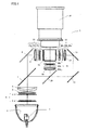
- Fig. 1 shows a 3-plate liquid crystal optical engine 1 in the first embodiment.
- a light emitting unit is a super high pressure mercury lamp, a metal halide lamp, a xenon lamp or the like, and emits light which is in turn collimated by a parabola reflector 3 and thus emanates therefrom, and is guided to an integrator lens 4.
- Integrator lens 4 is configured of a pair of lenses (fly eye lens) 4a and 4b. Each lens portion is adapted to guide the light that emanates from light source 2 to an entire surface of a liquid crystal light valve described hereinafter, to average partial, varying intensity present in light source 2 to reduce a difference in quantity of light between a center of a screen and a peripheral portion of the screen. Integrator lens 4 passes light, which in turn passes through a polarization conversion device 5 and a condenser lens 6 and is then guided to a first dichroic mirror 7.
- Polarization conversion device 5 is configured of a polarizing beam splitter array (hereinafter referred to as "PBS array").
- the PBS array includes a polarization separating film and a phase difference plate (a 1/2 ⁇ plate).
- the PBS array's each polarization separating film receives light from integrator lens 4 and, of the received light, for example transmits p polarized light and redirects s polarized light to have an optical path changed by 90°.
- the s polarized light having its optical path changed is reflected by an adjacent polarization separating film and thus emanates.
- the p polarized light transmitted through the polarization separating film is converted to s polarized light by the phase difference plate provided at a front side of the p polarized light (i.e., a side at which the light emanates), and thus emanates.
- the phase difference plate provided at a front side of the p polarized light (i.e., a side at which the light emanates), and thus emanates.
- almost all of light is converted to s polarized light.
- First dichroic mirror 7 transmits red color wavelength band light and reflects cyan (green plus blue) wavelength band light.
- the red color wavelength band light transmitted by first dichroic mirror 7 is reflected by a total reflection mirror 8 and thus has its optical path changed.
- the red color light reflected by total reflection mirror 8 passes through a lens 9 and is transmitted through a transmission liquid crystal light valve 31 for red color light and thus optically modulated.
- the cyan wavelength band light reflected by first dichroic mirror 7 is guided to a second dichroic mirror 10.
- Second dichroic mirror 10 transmits blue color wavelength band light and reflects green wavelength band light.
- the green wavelength band light reflected by second dichroic mirror 10 passes through a lens 11 and is guided to a transmission liquid crystal light valve 32 for green color light, and transmitted therethrough and thus optically modulated.
- the blue wavelength band light transmitted by second dichroic mirror 10 is guided via total reflection mirrors 12 and 13 and a lens 14 to a transmission liquid crystal light valve 33 for blue color light, and transmitted therethrough and thus optically modulated.
- Each liquid crystal light valve 31, 32, 33 is an optical modulation unit including incident polarization plates 31a, 32a, 33a, panel units 31b, 32b, 33b formed of a pair of glass substrates (provided with a pixel electrode, an orientation film and the like) and liquid crystal sealed between the glass substrates, and emanating polarization plates 31 c, 32c, 33c.
- liquid crystal light valves 31, 32, 33 or the light of each color of an image
- a cross dichroic prism 15 to be colored image light, which is in turn magnified by a projection lens 16 and thus projected, and thus displayed on a screen (not shown).
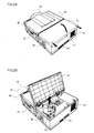
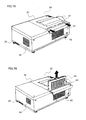
- FIGs. 2A and 2B are perspective views of a projection image display apparatus of the present invention in the first embodiment implemented as a projector 20.
- Fig. 2A shows projector 20 with a back case 21 drawn out frontward
- Fig. 2B shows projector 20 with back case 21 drawn out frontward and a light source unit 22 therein extracted therefrom.
- Projector 20 has a casing 28, which is provided with an optical engine 1, a main board (not shown), a cooling fan 45 (see Fig. 4 ), ventilation holes 23 and 24, an external equipment connector unit 25, a console panel 26, and the like.
- the main board (not shown) is powered on by a user to operate to variously control projector 20, such as an optical modulation function by optical engine 1, executing a specific operation performed by the user, transmitting/receiving and converting a signal received from and output to external equipment connector unit 25.
- variously control projector 20 such as an optical modulation function by optical engine 1, executing a specific operation performed by the user, transmitting/receiving and converting a signal received from and output to external equipment connector unit 25.
- Cooling fan 45 introduces external air through ventilation holes 23, 24 and the like to cool a heat generating portion of light source 2 or the like, and exhausts externally from projector 20 the air that has cooled the portion.
- External equipment connector unit 25 is a unit interfacing with external image equipment and is provided with a variety of connectors to accommodate a variety of specifications.
- Back case 21 is a portion of casing 28, and disengaging a screw 27 to open the case allows the case to expose light source unit 22.
- Fig. 3 is a perspective view of light source unit 22 of the present invention in the first embodiment.
- Light source unit 22 includes a light source 2, a lamp housing 30, a handle 31, protection glass 32, a light source connector 33, an authentication IC 34, and an authentication IC connector 35.
- Light source 2 is housed in lamp housing 30 and receives electric power through light source connector 33 to emit light of high intensity. Furthermore, as it is repeatedly used, light source 2 decreases in intensity and thus reaches the end of its life. Accordingly, after it is used for a period of time, light source 2 needs to be exchanged with a new light source.
- Lamp housing 30 is formed to position light source 2 and is preferably formed of a heat resistant resin which is capable of enduring the heat of light source 2 increased in temperature and also has low thermal conductivity.
- Handle 31 is provided at an upper surface of lamp housing 30 and formed to allow light source unit 22 to be easily held and extracted when back case 21 is opened.
- Protection glass 32 prevents a user from touching light source 2 generating heat.
- Light source connector 33 electrically connects the main board and light source 2, and light source connector 33 thus connected allows light source 2 to receive power supply.
- Authentication IC 34 is connected by authentication IC connector 35, which is disposed in a vicinity of light source connector 33 and configured of a power supply line and two communication lines provided for authentication IC 34, on a IIC bus or the like to a host CPU 40 (see Fig. 4 ), which is incorporated in the main board, to identify light source unit 22.
- Light source connector 33 and authentication IC connector 35 will be connected to a connector that is provided at the main board when a guidance mechanism (not shown) inserts light source unit 22 into projector 20.
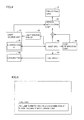
- Fig. 4 is a block diagram of a configuration detecting whether a light source is a genuine product according to the first embodiment of the present invention.
- Host CPU 40 exerts control to perform a predetermined operation performed when an optical modulation unit 41, a light source driver 42, a fan driver 43, and an OSD generation unit 44 normally operate.
- OSD is an abbreviation of "on-screen display” and is and will also be used hereinafter as a general term for displaying characters, symbols or the like on an image screen to notify a user of information of equipment or the like.
- host CPU 40 when host CPU 40 is activated, it initially transmits a sequence of random numbers to authentication IC 34.
- Authentication IC 34 receives the sequence of random numbers, and calculates an exclusive OR of the received sequence of random numbers with an encryption key sequence for encryption and returns it to host CPU 40.
- Host CPU 40 receives the encrypted, returned signal, and calculates an exclusive OR with the encryption key sequence to reconstruct the returned signal.
- the initial sequence of random numbers is compared with the reconstructed sequence of numbers and if they match, host CPU 40 can determine that light source unit 22 currently used is a genuine product, and host CPU 40 issues an instruction to optical modulation unit 41, light source driver 42 and fan driver 43 to normally operate.
- host CPU 40 can determine that light source unit 22 currently used is a non genuine product, and host CPU 40 issues an instruction to light source driver 42 to cause light source 2 to provide a reduced quantity of light, an instruction to fan driver 43 to cause cooling fan 45 to attain a maximum output level, and an instruction to OSD generation unit 44 to generate an OSD indicating that the light source unit is not a genuine product of a manufacturer.
- host CPU 40 makes a comparison with a specification of a light source unit of a genuine product and issues an instruction to light source driver 42 to provide a quantity of light estimated to be a minimum output level.
- authentication IC 34 is preferably for example an IC of a non general purpose product to prevent non genuine products from easily imitating it.
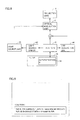
- OSD generation unit 44 When it is preferable to issue notification to a user involved in projector 20, OSD generation unit 44 generates and transmits a predetermined phrase, symbol and/or the like to optical modulation unit 41 to display it as an OSD together with an image or alone via projection lens 16 (see Fig. 5 ).
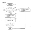
- Fig. 6 is a flowchart of an operation according to the first embodiment of the present invention.
- Projector 20 is powered on (S1), and in response, light source unit 22 is identified for whether it is a genuine product or a non genuine product (S3).
- light source driver 42 decreases the output of light source 2 (S7).
- fan driver 43 provides adjustment to cause cooling fan 45 to provide a maximum output in preparation for heat generated by light source 2 unexpectedly (S9).
- an OSD is displayed to inform the user that light source unit 22 currently used is a non genuine product (S11).
- Fig. 6 flowchart describes that whether light source unit 22 is a genuine product or not is identified when projector 20 is powered on (S1). Alternatively, whether light source unit 22 is a genuine product or not may be identified when light source unit 22 is attached to the main body of the apparatus.
- a light source that is a genuine product of a manufacturer that satisfies a specification of a component, safety for cooling, and the like should be used. If a light source that is not a manufacturer's genuine product is used, however, the manufacturer cannot provide sufficient verification thereon for safety or exert control in accordance with that lamp. In such a situation, using the non genuine product can invite an unexpected failure, and more specifically, there is a possibility that the light source may abnormally generate heat, which may in turn damage an optical component, a mechanism component and the like other than the light source.
- the configuration of the first embodiment can reduce the light source's abnormal heat generation as well as the possibility that the light source's abnormal heat generation invites a secondary damage to damage an optical component, a mechanism component and the like other than the light source.
- the configuration of the first embodiment allows a user necessitated to temporarily use a non genuine product to use it, and a disbenefit to the user can thus be avoided at least at a lowest level.
- filter 60 currently used is a genuine product, it satisfies a specification of a component, safety for cooling, and the like, and the normal operation is less likely to cause a problem.
- filter 60 currently used is a non genuine product, then there is one possibility that it has an insufficient ability to introduce sufficient air to cool a heat generating portion. Accordingly, an OSD is displayed to inform that filter 60 is a non genuine product. There is also another possibility that filter 60 has an insufficient ability to collect dust. Accordingly, an OSD is displayed to inform that filter 60 is a non genuine product.
- Figs. 7A and 7B are perspective views of projector 20 implementing the projection image display apparatus according to the second embodiment of the present invention.
- Fig. 7A shows projector 20 such that a side cover 61 housing filter 60 is opened
- Fig. 7B shows projector 20 with filter 60 extracted.
- Filter 60 is detachably attached on a ventilation path connecting a ventilation hole 62 and a heat generating component, and includes a filter film 63 blocking a flow path.
- Filter film 63 has a function to prevent fine dust and the like from passing therethrough and pass air therethrough.
- Filter 60 can thus remove fine dust included in external air introduced through ventilation hole 62 and prevent dust from adhering to an optical component and the like, and also allows a heat generating component to be cooled.
- filter 60 functions to remove dust and the like, it has dust and the like deposited thereon as it is used for a long period of time.
- the deposited dust prevents external air from flowing in and thus contributes to a reduced amount of external air introduced. Accordingly in view of protecting a heat generating component it is necessary to exchange filter 60 on a regular basis.
- Fig. 8 is a block diagram of a configuration detecting whether a filter is a genuine product according to the second embodiment of the present invention.
- filter 60 and authentication IC 34 provided to filter 60 are introduced.
- host CPU 40 When host CPU 40 is activated, it initially transmits a sequence of random numbers to authentication IC 34.
- Authentication IC 34 receives the sequence of random numbers, and calculates an exclusive OR of the received sequence of random numbers with an encryption key sequence for encryption and returns it to host CPU 40.
- Host CPU 40 receives the encrypted, returned signal, and calculates an exclusive OR with the encryption key sequence to reconstruct the returned signal.
- the initial sequence of random numbers is compared with the reconstructed sequence of numbers and if they match, host CPU 40 can determine that filter 60 currently used is a genuine product, and host CPU 40 issues an instruction to optical modulation unit 41 and light source driver 42 to normally operate.
- host CPU 40 can determine that filter 60 currently used is a non genuine product, and host CPU 40 issues an instruction to OSD generation unit 44 to generate and display an OSD indicating that the filter is not a genuine product of a manufacturer (see Fig. 9 ).
- authentication IC 34 is preferably for example an IC of a non general purpose product to prevent non genuine products from easily imitating it.
- Fig. 10 is a flowchart of an operation according to the second embodiment of the present invention.
- Projector 20 is powered on (S21), and in response, filter 60 is identified for whether it is a genuine product or a non genuine product (S23).
- filter 60 is a genuine product (YES at S23), it is less likely to cause a failure, and each component configuring projector 20 is normally operated (S25). If filter 60 is a non genuine product (NO at S23), an OSD is displayed to inform the user that filter 60 currently used is a non genuine product (S27).
- Fig. 10 flowchart describes that whether filter 60 is a genuine product or not is identified when projector 20 is powered on (S21). Alternatively, whether filter 60 is a genuine product or not may be identified when filter 60 is attached to the main body of the apparatus.
- a filter that is a genuine product of a manufacturer that satisfies a specification of a component, safety for cooling, and the like should be used. If a filter that is not a manufacturer's genuine product is used, however, it can invite an unexpected failure, and more specifically, there is a possibility that the light source may abnormally generate heat, which may in turn damage an optical component, a mechanism component and the like other than the light source, or the optical component may suffer dust adhering thereto.
- the configuration of the second embodiment can inform a user before the light source abnormally generates heat, which may in turn invite a secondary damage to damage an optical component, a mechanism component and the like other than the light source, or the optical component has dust adhering to.
- the configuration of the second embodiment can thus provide an opportunity to obviate such problems.
- the configuration of the second embodiment allows a user necessitated to temporarily use a non genuine product to use it, and a disbenefit to the user can thus be avoided at least at a lowest level.
- light source 2 is controlled to provide an output of a reduced level.
- light source 2 may completely be turned off. This can also reduce the possibility that the light source may abnormally generate heat, which may in turn invite a secondary damage to damage an optical component, a mechanism component and the like other than the light source.
- the present invention is not limited thereto, and is applicable to a projection image display apparatus including a different type of image light generation system, and can also be applied in the DLP (Digital Light Processing) system, a registered trademark of Texas Instruments Incorporated, and the LCOS (Liquid Crystal on Silicon) system.
- DLP Digital Light Processing
- LCOS Liquid Crystal on Silicon
- authentication IC 34 corresponds in the present invention to an embodiment of a storage unit and host CPU 40 corresponds in the present invention to an embodiment of a determination unit or a determination means.
- light source driver 42 corresponds in the present invention to an embodiment of a light source control unit or a light source control means.
- cooling fan 45 corresponds in the present invention to an embodiment of a cooling unit and fan driver 43 corresponds in the present invention to an embodiment of a cooling control unit or a cooing control means.
- OSD generation unit 44 corresponds in the present invention to an embodiment of an OSD device.
Landscapes
- Physics & Mathematics (AREA)
- General Physics & Mathematics (AREA)
- Engineering & Computer Science (AREA)
- Computer Security & Cryptography (AREA)
- Projection Apparatus (AREA)
- Transforming Electric Information Into Light Information (AREA)
- Liquid Crystal (AREA)
Applications Claiming Priority (1)
| Application Number | Priority Date | Filing Date | Title |
|---|---|---|---|
| JP2008178303A JP5247268B2 (ja) | 2008-07-08 | 2008-07-08 | 投射型映像表示装置 |
Publications (2)
| Publication Number | Publication Date |
|---|---|
| EP2144114A2 true EP2144114A2 (de) | 2010-01-13 |
| EP2144114A3 EP2144114A3 (de) | 2010-07-07 |
Family
ID=41066748
Family Applications (1)
| Application Number | Title | Priority Date | Filing Date |
|---|---|---|---|
| EP09008880A Withdrawn EP2144114A3 (de) | 2008-07-08 | 2009-07-07 | Projektionsbildanzeigegerät mit der Fähigkeit der Identifizierung von Ersatzteilen |
Country Status (4)
| Country | Link |
|---|---|
| US (1) | US8523368B2 (de) |
| EP (1) | EP2144114A3 (de) |
| JP (1) | JP5247268B2 (de) |
| CN (1) | CN101625514B (de) |
Cited By (1)
| Publication number | Priority date | Publication date | Assignee | Title |
|---|---|---|---|---|
| CN105676579A (zh) * | 2016-03-18 | 2016-06-15 | 苏州佳世达光电有限公司 | 投影装置及投影灯更换判定方法 |
Families Citing this family (9)
| Publication number | Priority date | Publication date | Assignee | Title |
|---|---|---|---|---|
| JP2010204339A (ja) * | 2009-03-03 | 2010-09-16 | Seiko Epson Corp | プロジェクター |
| JP5402665B2 (ja) * | 2010-01-19 | 2014-01-29 | ソニー株式会社 | プロジェクタ装置 |
| JP2011237725A (ja) * | 2010-05-13 | 2011-11-24 | Sanyo Electric Co Ltd | 投写型表示装置 |
| JP5533229B2 (ja) * | 2010-05-14 | 2014-06-25 | パナソニック株式会社 | 投射型画像表示装置およびエアフィルタ制御方法 |
| US9066421B1 (en) | 2011-11-09 | 2015-06-23 | Rex Eric Martin | Holding apparatus for retaining a generally flat-shaped item, such as a hand-held electronic device |
| CN103197495B (zh) * | 2012-01-04 | 2015-06-10 | 中强光电股份有限公司 | 气体过滤模块及投影装置 |
| JP2014209183A (ja) * | 2013-03-27 | 2014-11-06 | セイコーエプソン株式会社 | エアフィルター及びプロジェクター |
| JP6338689B2 (ja) * | 2014-03-28 | 2018-06-06 | コーニンクレッカ フィリップス エヌ ヴェKoninklijke Philips N.V. | 陽電子放出断層撮影においけるデッドピクセル識別 |
| JP5869713B1 (ja) * | 2015-04-13 | 2016-02-24 | フェニックス電機株式会社 | 光源装置及び露光装置とその検査方法 |
Citations (2)
| Publication number | Priority date | Publication date | Assignee | Title |
|---|---|---|---|---|
| JP2000131758A (ja) | 1998-10-26 | 2000-05-12 | Minolta Co Ltd | プロジェクタ |
| JP2000131759A (ja) | 1998-10-26 | 2000-05-12 | Minolta Co Ltd | プロジェクタ |
Family Cites Families (24)
| Publication number | Priority date | Publication date | Assignee | Title |
|---|---|---|---|---|
| JP3446912B2 (ja) * | 1995-02-17 | 2003-09-16 | ソニー株式会社 | プロジェクタ装置 |
| EP1395092B1 (de) * | 1996-04-10 | 2006-05-31 | Seiko Epson Corporation | Lichtquelleneinheit, Lichtquellengerät und Projektionsanzeigengerät |
| US5855488A (en) * | 1997-09-19 | 1999-01-05 | In Focus Systems, Inc. | Protection lamp safety interconnect apparatus and method |
| JP3517583B2 (ja) * | 1998-03-27 | 2004-04-12 | キヤノン株式会社 | 露光装置、デバイス製造方法及び放電灯 |
| JP3572982B2 (ja) * | 1999-02-19 | 2004-10-06 | セイコーエプソン株式会社 | 投写型表示装置 |
| JP2002341442A (ja) * | 2001-05-16 | 2002-11-27 | Matsushita Electric Ind Co Ltd | 投射型画像表示装置 |
| US6755541B2 (en) * | 2001-05-22 | 2004-06-29 | Seiko Epson Corporation | Projector |
| US6839511B2 (en) | 2002-01-31 | 2005-01-04 | Olympus Optical Co., Ltd. | Camera system, camera, accessory device and method for judging and controlling an accessory device |
| US6738574B2 (en) | 2002-01-31 | 2004-05-18 | Olympus Optical Co., Ltd. | Camera system and accessory device |
| JP2003234982A (ja) * | 2002-02-08 | 2003-08-22 | Hitachi Ltd | 映像表示装置 |
| JP2003330112A (ja) * | 2002-05-16 | 2003-11-19 | Nec Viewtechnology Ltd | プロジェクタ及びそれに用いるランプ情報管理方法 |
| JP3791613B2 (ja) * | 2003-05-21 | 2006-06-28 | 船井電機株式会社 | 画像表示プロジェクタ |
| CN1570755A (zh) * | 2003-07-15 | 2005-01-26 | 乐金电子(沈阳)有限公司 | 投影仪空气过滤器更换时间判断装置及其表示方法 |
| US6956490B2 (en) * | 2003-07-28 | 2005-10-18 | Hewlett-Packard Development Company, L.P. | Projector with consumable component having memory device |
| GB2438909B (en) * | 2003-07-28 | 2008-02-13 | Hewlett Packard Development Co | Projector with consumable component having memory device |
| JP2006091610A (ja) * | 2004-09-27 | 2006-04-06 | Sanyo Electric Co Ltd | 投写型映像表示装置 |
| US20060087622A1 (en) * | 2004-10-21 | 2006-04-27 | Brown Stephen J | Projector apparatus and methods |
| JP2007073707A (ja) * | 2005-09-06 | 2007-03-22 | Seiko Epson Corp | 電子機器、および電子機器の制御方法 |
| DE102005050635B4 (de) * | 2005-10-20 | 2016-06-09 | Knorr-Bremse Systeme für Nutzfahrzeuge GmbH | System und Verfahren zum Erkennen von Eigenschaften einer Luftfilterpatrone |
| JP5068474B2 (ja) * | 2006-04-20 | 2012-11-07 | Necディスプレイソリューションズ株式会社 | 投写型表示装置 |
| JP2008185712A (ja) * | 2007-01-29 | 2008-08-14 | Seiko Epson Corp | 投射型表示装置及び投射用光源ユニット |
| JP5136824B2 (ja) * | 2007-03-09 | 2013-02-06 | ソニー株式会社 | プロジェクタおよびその制御方法 |
| JP5082680B2 (ja) * | 2007-08-28 | 2012-11-28 | ソニー株式会社 | ランプ駆動装置およびその制御方法 |
| JP2010113014A (ja) * | 2008-11-04 | 2010-05-20 | Sanyo Electric Co Ltd | 投射型映像表示装置 |
-
2008
- 2008-07-08 JP JP2008178303A patent/JP5247268B2/ja not_active Expired - Fee Related
-
2009
- 2009-06-18 CN CN200910147369.4A patent/CN101625514B/zh not_active Expired - Fee Related
- 2009-07-07 US US12/499,007 patent/US8523368B2/en not_active Expired - Fee Related
- 2009-07-07 EP EP09008880A patent/EP2144114A3/de not_active Withdrawn
Patent Citations (2)
| Publication number | Priority date | Publication date | Assignee | Title |
|---|---|---|---|---|
| JP2000131758A (ja) | 1998-10-26 | 2000-05-12 | Minolta Co Ltd | プロジェクタ |
| JP2000131759A (ja) | 1998-10-26 | 2000-05-12 | Minolta Co Ltd | プロジェクタ |
Cited By (1)
| Publication number | Priority date | Publication date | Assignee | Title |
|---|---|---|---|---|
| CN105676579A (zh) * | 2016-03-18 | 2016-06-15 | 苏州佳世达光电有限公司 | 投影装置及投影灯更换判定方法 |
Also Published As
| Publication number | Publication date |
|---|---|
| US20100007856A1 (en) | 2010-01-14 |
| JP5247268B2 (ja) | 2013-07-24 |
| CN101625514B (zh) | 2011-12-14 |
| JP2010019927A (ja) | 2010-01-28 |
| US8523368B2 (en) | 2013-09-03 |
| CN101625514A (zh) | 2010-01-13 |
| EP2144114A3 (de) | 2010-07-07 |
Similar Documents
| Publication | Publication Date | Title |
|---|---|---|
| US8523368B2 (en) | Projection display apparatus having stored information for authenticating light source | |
| JP3829813B2 (ja) | プロジェクタ | |
| JP4710657B2 (ja) | プロジェクタ | |
| JP3572982B2 (ja) | 投写型表示装置 | |
| US7976171B2 (en) | Projector cooling system with time dependent temperature threshold | |
| US7784951B2 (en) | Electronic instrument and USB device | |
| CN102736379B (zh) | 投影机 | |
| EP1363451A1 (de) | Projektor und Verfahren für das Verwalten von Informationen über die Projektionslampe | |
| US9086616B2 (en) | Projection display device | |
| CN102135714B (zh) | 投射型显示装置 | |
| US9088732B2 (en) | Projection display device | |
| US8118436B2 (en) | Projection image display apparatus | |
| US8888293B2 (en) | Image projection apparatus having an insertable and extractable optical element | |
| US20100110392A1 (en) | Projection Image Display Apparatus | |
| US8205993B2 (en) | Projection-type image displaying apparatus | |
| US20120154763A1 (en) | Projection display device | |
| JP5125367B2 (ja) | プロジェクタ | |
| CN107966873A (zh) | 光源装置及投影机 | |
| JP2008241895A (ja) | プロジェクタ | |
| JP2006071929A (ja) | 画像表示装置 | |
| JP4930122B2 (ja) | 光源ユニット、照明ユニット、光源装置、照明ユニット、プロジェクタ及びモニタ装置 | |
| JP4055420B2 (ja) | 光源装置およびこの光源装置を備えるプロジェクタ | |
| JP4349021B2 (ja) | プロジェクタ | |
| JP2011002613A (ja) | プロジェクター | |
| JP4711017B2 (ja) | プロジェクタ |
Legal Events
| Date | Code | Title | Description |
|---|---|---|---|
| PUAI | Public reference made under article 153(3) epc to a published international application that has entered the european phase |
Free format text: ORIGINAL CODE: 0009012 |
|
| AK | Designated contracting states |
Kind code of ref document: A2 Designated state(s): AT BE BG CH CY CZ DE DK EE ES FI FR GB GR HR HU IE IS IT LI LT LU LV MC MK MT NL NO PL PT RO SE SI SK SM TR |
|
| RIC1 | Information provided on ipc code assigned before grant |
Ipc: G03B 21/20 20060101ALI20100325BHEP Ipc: G03B 21/16 20060101ALI20100325BHEP Ipc: G03B 21/14 20060101AFI20090923BHEP |
|
| PUAL | Search report despatched |
Free format text: ORIGINAL CODE: 0009013 |
|
| AK | Designated contracting states |
Kind code of ref document: A3 Designated state(s): AT BE BG CH CY CZ DE DK EE ES FI FR GB GR HR HU IE IS IT LI LT LU LV MC MK MT NL NO PL PT RO SE SI SK SM TR |
|
| AX | Request for extension of the european patent |
Extension state: AL BA RS |
|
| 17P | Request for examination filed |
Effective date: 20101223 |
|
| 17Q | First examination report despatched |
Effective date: 20130513 |
|
| STAA | Information on the status of an ep patent application or granted ep patent |
Free format text: STATUS: THE APPLICATION HAS BEEN WITHDRAWN |
|
| 18W | Application withdrawn |
Effective date: 20130704 |