EP2144037A1 - Laser de construction, en particulier un laser de construction rotatif correcteur, et procédé de mesure de l'inclinaison d'un axe de rotation d'un laser de construction - Google Patents
Laser de construction, en particulier un laser de construction rotatif correcteur, et procédé de mesure de l'inclinaison d'un axe de rotation d'un laser de construction Download PDFInfo
- Publication number
- EP2144037A1 EP2144037A1 EP08104698A EP08104698A EP2144037A1 EP 2144037 A1 EP2144037 A1 EP 2144037A1 EP 08104698 A EP08104698 A EP 08104698A EP 08104698 A EP08104698 A EP 08104698A EP 2144037 A1 EP2144037 A1 EP 2144037A1
- Authority
- EP
- European Patent Office
- Prior art keywords
- tilt
- axis
- rotation
- sensor
- tilt sensor
- Prior art date
- Legal status (The legal status is an assumption and is not a legal conclusion. Google has not performed a legal analysis and makes no representation as to the accuracy of the status listed.)
- Withdrawn
Links
Images


Classifications
-
- G—PHYSICS
- G01—MEASURING; TESTING
- G01C—MEASURING DISTANCES, LEVELS OR BEARINGS; SURVEYING; NAVIGATION; GYROSCOPIC INSTRUMENTS; PHOTOGRAMMETRY OR VIDEOGRAMMETRY
- G01C15/00—Surveying instruments or accessories not provided for in groups G01C1/00 - G01C13/00
- G01C15/002—Active optical surveying means
- G01C15/004—Reference lines, planes or sectors
Definitions
- the invention relates to a construction laser, in particular a self-compensating rotating construction laser, with the features in the preamble of claim 1 and a method for measuring a tilt of an axis of rotation of a construction laser.
- Rotating construction lasers are well known in the prior art.
- a construction laser with at least one laser beam defining a plane is described.
- the construction laser has a laser unit that is tiltable relative to a housing around at least one swiveling axis.
- the construction laser includes at least one leveling sensor which is sensitive to the swiveling axis for a highly precise orientation to the gravitational field.
- the device further includes one tilt sensor which is sensitive to the swiveling axis for direct measurement of an inclination angle relative to the gravitational field.
- Disadvantageous in this embodiment is that a level sensor and a tilt sensor are needed to perform the tilt measurement with an acceptable degree of accuracy. Furthermore, the laser beam unit periodically needs to return to its level position for recalibrating the tilt sensor.
- WO 2008/052590 A1 relates to indicating a grade, e. g. in construction applications, using a laser beam.
- the laser beam is emitted from a laser unit to a desired direction having a grade angle with regard to the level angle.
- a level sensor is provided for adjusting the level angle and a grade sensor is provided for indicating a grade angle on the basis of the level angle from the level sensor.
- This device also requires two sensors to correctly indicate the grade.
- fixed tilt detectors are fixed in planes crossing perpendicularly to each other of a shaft center of a laser projector, and tilting tilt detectors are mounted on a plate which is tiltable with respect to the shaft center of the laser projector.
- the laser projector is level in such a manner that the fixed tilt detectors indicate horizontal direction.
- the tilting tilt detectors are aligned with the fixed tilt detectors and indicate a horizontal direction.
- a horizontal reference plane is obtained.
- the tilting tilt detectors are tilted with the fixed tilt detectors as a reference and the laser projector is leveled so that the tilting tilt detectors indicate horizontal direction.
- a reference plane tilted at an arbitrary angle is obtained.
- This device also requires multiple tilt sensors.
- two tilt sensors are usually used for measuring the tilt of an axis of rotation of a rotating construction laser with high accuracy.
- One of these sensors is a level sensor which is of very high precision and very limited range and which is used to calibrate the grade sensor or tilt sensor, which has a broader range, but is less precise.
- the construction laser should be able to continuously generate a tilted laser beam plane without returning periodically to a level position.
- the construction laser in particular a self-compensating rotating construction laser, comprises a base; a means for generating a laser beam plane, wherein the laser beam plane is created by a laser beam rotating around an axis of rotation, and wherein the means for generating the laser beam plane are pivotably mounted to the base, wherein the means for generating the laser beam plane is pivotable relative to an X-axis and/or a Y-axis; and a tilt sensor for measuring the tilt of the axis of rotation.
- the tilt sensor is pivotable around the axis of rotation for measuring the tilt of the axis of rotation in at least two positions.
- the device requires only one tilt sensor to accurately measure the tilt of the axis of rotation. This is achieved by measuring the tilt in at least two different positions and computing the effective tilt. Thereby errors are eliminated that may result from the tilt sensor, e.g. temperature drift or hysteresis error.
- the design is a lot cheaper than other devices known in the prior art. Furthermore, it does not require the construction laser to return to the level position in order to recalibrate the tilt sensor.
- the tilt sensor is pivotable between at least two defined positions.
- a defined position is a position in which a tilt measurement is taken. This enables continuous measurements of the tilt of the axis of rotation.
- the tilt of the means for generating a laser beam plane can be adjusted during operation.
- the two defined positions may be diametrically opposite of each other relative to the axis of rotation. Thus, alignment errors of the tilt sensor relative to the axis of rotation can be computationally eliminated.
- the tilt sensor is pivotable between an uneven number of defined positions.
- the average tilt is computed taking into account the positions at which the measurements were taken.
- the tilt sensor is mounted to a pivotable sensor platform.
- the sensor platform is a structure that carries the tilt sensor.
- the means for generating the laser beam plane can further include an axle that is concentric to the axis of rotation, wherein the sensor platform is pivotably mounted to the axle.
- the axle provides a means around which the sensor platform may be pivoted or rotated. It may also serve as an axle for another part of the means for generating the laser beam plane.
- two bearings are located between a sensor platform and the axle, wherein the bearings are arranged at a distance from another of at least one bearing width.
- the pivoting movement of the sensor platform is very stable with respect to the axis of rotation of the laser beam.
- the tilt sensor is always closely aligned with the axis of rotation-in the defined positions as well as during pivoting motion. This helps to reduce errors resulting from the pivotable mounting of the sensor platform to the axle.
- a printed circuit board may be provided between the tilt sensor and the sensor platform.
- the tilt sensor may be connected to the circuit board, and the circuit board again may be connected to a control unit. This represents an efficient design for transmitting the signal output of the tilt sensor to the control unit.
- the tilt sensor is pivoted by an engaging pin that is provided on a rotating part of the means for generating the laser beam plane.
- just one motor is required to rotate the laser beam and to pivot the tilt sensor.
- the tilt sensor can alternatively be pivoted by a pivoting motor according to another embodiment of the invention.
- the pivoting motor may be switched by position switches.
- the position switches include a light emitting diode (LED) and a photo detector which are placed on parts that are moving relative to each other. The LED is placed at a defined position of the tilt sensor. If the photo detector detects a change in the light intensity, it will turn off the pivoting motor exactly at the defined position.
- the pivoting motor may be a stepper motor.
- the stepper motor is programmed to turn the sensor platform a predefined number of steps which corresponds to the distance between the defined positions.
- the counter of the stepper motor is reset by the position switches.
- the tilt sensor may be an accelerometer.
- the accelerometer may be a part of an integrated circuit. Accelerometers have been shown to provide tilt measurements of very high accuracy.
- the tilt of the axis of rotation is measured with a tilt sensor at a main position of the tilt sensor and at least one other position of the tilt sensor, wherein a compensating value is generated out of the tilt measurement at the other position to adjust the tilt measurement of the tilt sensor at the main position.
- the tilt sensor may be pivoted between at least two defined positions.
- the two positions are opposite of each other relative to the axis of rotation.
- the tilt sensor is pivoted between an uneven number of defined positions.
- the results of the tilt measurements at the defined positions can be advantageously used to calibrate the sensitivity of the tilt sensor.
- a construction laser 1 is shown in two views-one from the front and one from the right hand side.
- the construction laser 1 comprises a base 2 in form of a housing.
- a means 3 for generating a laser beam plane is pivotably mounted to the base 2 using a pivoting system 4 that may be a spherical joint or a gimbal.
- the pivoting system 4 allows the means 3 for generating the laser beam plane to swivel around an X- and a Y-axis.
- the means 3 for generating a laser beam plane comprises a hollow axle 5.
- the pivoting system 4 is attached to the axle 5 approximately at midsection.
- the axle 5 has a lower end 6 and an upper end 7.
- a laser collimator unit 8 is located in the interior of the hollow axle 5 at the lower end 6.
- the laser collimator unit 8 comprises a laser diode 9 and a collimator 10.
- the laser collimator unit 8 generates a collimated laser beam 11 that is directed along the center line 12 of the axle 5 towards a head assembly 13.
- the head assembly 13 comprises an optically transparent hood 14 that is rotatably mounted to the axle 5 using two bearings 15, 16.
- a laser beam redirector 17 in the form of a prism is integrated into the hood 14.
- the laser beam redirector 17 changes the direction of the laser beam 11 by an angle of 90°. Since the laser beam redirector 17 is rotated with the hood 14, a laser beam plane is generated in which the laser beam 11 rotates around an axis 18 of rotation.
- Said axis 18 of rotation is concentric to the center line 12 of the axle 5.
- the head assembly 13 further comprises a rotating motor that rotates the hood via a string (see Fig. 6 ).
- the hood 14 is rotated at a speed of several thousand revolutions per minute (rpm).
- a tilt sensor 19 is provided.
- the tilt sensor 19 is mounted to a sensor platform 20 using a printed circuit board 21.
- the sensor platform 20 is pivotably mounted to the axle 5 using two bearings 22, 23.
- the bearings 22, 23 are spaced apart at a distance D of one bearing width.
- the distance D between the bearings 22, 23 stabilizes the pivoting movement of the tilt sensor 19.
- the tilt sensor 19 is aligned with the axis 18 of rotation.
- the interior surface 24 of the sensor platform 20 is preferentially parallel to the axis 18 of rotation and also perpendicular to a mounting surface 25 to which the printed circuit board 21 is attached.
- a counter weight 26 is provided directly opposite of the tilt sensor 19 on the printed circuit board 21.
- the counter 26 weight may be replaced by second tilt sensor. This second tilt sensor may be used parallel to previous tilt sensor 19 or as a backup.
- the tilt sensor 19 is configured to measure the tilt of the axis 18 of rotation relative to the X-axis and the Y-axis.
- two tilt sensors may be provided on the sensor platform 20, wherein one tilt sensor measures the tilt of the axis 18 of rotation about the X-axis and the other tilt sensor measures the tilt of the axis 3 of rotation about the Y-axis. These two tilt sensors may be arranged at a right angle to each other relative to the axis 18 of rotation.
- the sensor platform 20 is pivoted by a pivoting motor 27.
- the pivoting motor 27 is a direct current (DC) motor.
- a pinion 28 is mounted to the drive shaft 29 of the pivoting motor 27 and is engaged with an external tooth system 30 on the sensor platform 20.
- On the bottom side 31 of the sensor platform 20, a pin 32 is provided to restrict the pivoting movement of the sensor platform 20.
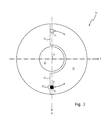
- the pin 32 engages with stops 33 that are provided on two defined diametrically opposite positions 54, 55 (see Fig. 3 ) on the stopping disc 34.
- the stopping disc is shown to be separate from the axle 5.
- the stopping disc 34 may be provided as an integral part of the axle 5.
- pivoting motor 27 is always powered with a minimum current to generate a mechanical torque which pushes the pin 32 against one of the stops 33.
- a main printed circuit board 35 is mounted to the lower end 6 of the axle 5. Attached and/or connected to this main printed circuit board 35 is a control unit 36, the laser diode 9, the pivoting motor 27 and the tilt sensor 19 (via wires 37 and the other printed circuit board 21).
- Two leveling arms 38, 39 that are perpendicular to each other are attached to the stopping disc 34.
- the leveling arms 38, 39 are provided with leveling pins 40, 41 that engage with leveling drives for tilting the means 3 for generating a laser beam plane relative to the X-axis and the Y-axis.
- the leveling drives are not shown in the figures.
- the tilt sensor 19 is pivoted into one defined position that is the main position 54 (see Fig. 3 ).
- the means 3 for generating a laser beam plane are pivoted according to the measurements of the tilt sensor 19 in the main position 54.
- the tilt sensor 19 is pivoted upon a trigger signal into the other defined position 55 to measure the tilt of the axis 18 of rotation at that position which is used as a compensating value for the tilt measurements of the tilt sensor 19 in the main position 54.
- the tilt sensor 19 is pivoted back to its main position 54.
- the trigger signal can be a change in temperature, a periodic signal of a timer, and/or a signal generated at start-up of the construction laser.
- the stopping disc 34 is shown in figure 3 in a top view.
- the stopping disc 34 has a hole 50 in the middle for mounting it to the axle 5.
- a clearance 51 is provided for the pin 32 which is mounted to the bottom side 31 of the sensor platform 20.
- the clearance 51 has the shape of a portion of a ring disc.
- a magnet 53 is integrated into one of the stops 33 to attract the pin 32. Once the pin 32 is attracted, the pin 32 is held at the stop 33. It is no longer required to generate a torque with the pivoting motor 27.
- the motor force overcomes the magnetic force and moves the sensor platform 20 into the other defined position 55. A constant force is applied by the pivoting motor 27 to hold the sensor platform 20 in that defined position 55 until the tilt measurement is completed. Then the pivoting motor 27 pivots the sensor platform 20 back to its main position 54 where the pin 32 abuts against the magnet 53.
- FIG 4 another embodiment of the construction laser 60 is shown in a side view.
- the pivoting motor 27 is a stepper motor. A certain number of steps corresponds to a rotation of the tilt sensor 19 into the next desired defined position 54, 55.
- an electrical position switching system 61 is used.
- the position switching system 61 comprises a light emitting diode (LED) 62 and a photo detector 63.
- the LED 62 is located at the bottom side 31 of the sensor platform 19 and is connected to the printed circuit board 21 on the sensor platform 20.
- the photo detector 63 is provided on the main printed circuit board 35. During operation, the sensor platform 21 is pivoted until the photo detector 63 receives light from the LED 62.
- stepper motor 27 and the position switching system 61 replace the pin 32 and the stopping disc 34 of the previous figures 1 and 2 .
- the defined positions 54, 55 into which the tilt sensor 19 may be pivoted may be exactly opposite of each other relative to the axis 18 of rotation as shown in figure 3 , but the defined positions 70, 71 may also be at a right angle to each other (see Fig. 5a ). Furthermore, more than two defined positions 72 may be provided, as is shown in figures 5b to 5d . As described above, an uneven number of three or more defined positions 72 is preferred for very precise tilt measurements of the axis 18 of rotation. Those defined positions 72 are evenly distributed on a reference circle 73 concentric to the axis 18 of rotation.
- a construction laser 80 with a head assembly 81 is provided with a pentaprism 82 for redirecting the laser beam 83.
- the pentaprism 82 is mounted on top of a hood 84.
- the laser beam 83 is generated by the laser collimator unit 85 is guided through a hole 99 in the hood 84 directly to the pentaprism 82.
- the sensor platform 86 is pivoted by a pivoting motor 87 that is mounted to an arm 88 that is provided on one side of an axle 89 at midsection.
- the sensor platform 86 is mounted to the axle 89 via two radial bearings 22, 23 which are kept apart by two bushings 90, 91 that are contacting the outer and inner rings of the bearings 22, 23.
- the bushings 90, 91 are of slightly different lengths.
- the bearings 22, 23 at the upper end 92 and at the lower end 93 of the axle 89 are held by wave springs 94 and retaining rings 95 which are placed in grooves.
- the wave springs 94 bias against the inner rings of the outer bearings 16, 23 to create a preload on the bearings 15, 16, 22, 23.
- a tilt sensor 96 is aligned with the axis 18 of rotation.
- An interior surface 97 of the sensor platform 86 is advantageously arranged to be parallel to the axis 18 of rotation and is machined to be perpendicular to a tilt sensor mounting surface 98.
- a further embodiment of a construction laser 100 is shown in which a hood 101 is rotated by a rotating motor 102 via a string 103 or belt using a pulley 104.
- a rotating motor 102 Via string 103 or belt using a pulley 104.
- an engaging pin 106 At the bottom side 105 of the hood 101 an engaging pin 106 is provided which engages with a mechanical actuator 107 fixed to a sensor platform 108 to pivot the tilt sensor 109.
- the mechanical actuator 107 may be configured with a counter to pivot the tilt sensor 109 only after the engaging pin 106 has passed a certain number of times.
- control unit 110 is configured to lock the mechanical actuator 107 into the engaging pin 106.
- the direction of turn of the rotating motor 102 may be reversible to pivot the tilt sensor 109 into a defined position 54, 55 and back again. After each pivoting movement the mechanical actuator 107 is disengaged from the engaging pin 106 by the control unit 110. Afterwards the speed of the rotating motor 102 returns to normal operational levels of several thousand revolutions per minute in order to generate the laser beam plane.
- a ball joint 113 is provided for pivotably mounting the means 114 for generating a laser beam plane to a base 115.
Priority Applications (7)
| Application Number | Priority Date | Filing Date | Title |
|---|---|---|---|
| EP08104698A EP2144037A1 (fr) | 2008-07-10 | 2008-07-10 | Laser de construction, en particulier un laser de construction rotatif correcteur, et procédé de mesure de l'inclinaison d'un axe de rotation d'un laser de construction |
| PCT/EP2009/058807 WO2010004024A2 (fr) | 2008-07-10 | 2009-07-10 | Laser rotatif de construction, en particulier laser rotatif de construction auto-compensateur, et procédé de mesure d’une inclinaison d’un axe de rotation d’un laser de construction |
| EP09780423.1A EP2310800B1 (fr) | 2008-07-10 | 2009-07-10 | Laser de construction et procédé de mesure de l'inclinaison d'un axe de rotation d'un laser de construction |
| US13/002,409 US8407903B2 (en) | 2008-07-10 | 2009-07-10 | Rotating construction laser, in particular a self-compensating rotating construction laser, and method for measuring a tilt of an axis of rotation of a construction laser |
| CN200980126706XA CN102089619B (zh) | 2008-07-10 | 2009-07-10 | 旋转构造激光器,具体为自补偿的旋转构造激光器以及用于测量构造激光器的旋转轴线的倾斜的方法 |
| CA2730213A CA2730213C (fr) | 2008-07-10 | 2009-07-10 | Laser rotatif de construction, en particulier laser rotatif de construction auto-compensateur, et procede de mesure d'une inclinaison d'un axe de rotation d'un laser de construction |
| AU2009267983A AU2009267983B2 (en) | 2008-07-10 | 2009-07-10 | Rotating construction laser, in particular a self-compensating rotating construction laser, and method for measuring a tilt of an axis of rotation of a construction laser |
Applications Claiming Priority (1)
| Application Number | Priority Date | Filing Date | Title |
|---|---|---|---|
| EP08104698A EP2144037A1 (fr) | 2008-07-10 | 2008-07-10 | Laser de construction, en particulier un laser de construction rotatif correcteur, et procédé de mesure de l'inclinaison d'un axe de rotation d'un laser de construction |
Publications (1)
| Publication Number | Publication Date |
|---|---|
| EP2144037A1 true EP2144037A1 (fr) | 2010-01-13 |
Family
ID=40291215
Family Applications (2)
| Application Number | Title | Priority Date | Filing Date |
|---|---|---|---|
| EP08104698A Withdrawn EP2144037A1 (fr) | 2008-07-10 | 2008-07-10 | Laser de construction, en particulier un laser de construction rotatif correcteur, et procédé de mesure de l'inclinaison d'un axe de rotation d'un laser de construction |
| EP09780423.1A Active EP2310800B1 (fr) | 2008-07-10 | 2009-07-10 | Laser de construction et procédé de mesure de l'inclinaison d'un axe de rotation d'un laser de construction |
Family Applications After (1)
| Application Number | Title | Priority Date | Filing Date |
|---|---|---|---|
| EP09780423.1A Active EP2310800B1 (fr) | 2008-07-10 | 2009-07-10 | Laser de construction et procédé de mesure de l'inclinaison d'un axe de rotation d'un laser de construction |
Country Status (6)
| Country | Link |
|---|---|
| US (1) | US8407903B2 (fr) |
| EP (2) | EP2144037A1 (fr) |
| CN (1) | CN102089619B (fr) |
| AU (1) | AU2009267983B2 (fr) |
| CA (1) | CA2730213C (fr) |
| WO (1) | WO2010004024A2 (fr) |
Cited By (4)
| Publication number | Priority date | Publication date | Assignee | Title |
|---|---|---|---|---|
| US20110099822A1 (en) * | 2008-07-10 | 2011-05-05 | Leica Geosystems Ag | Rotating construction laser, in particular a self-compensating rotating construction laser, and method for measuring a tilt of an axis of rotation of a construction laser |
| EP2458326A1 (fr) | 2010-11-25 | 2012-05-30 | Leica Geosystems AG | Laser rotatif |
| EP2455711A3 (fr) * | 2010-11-22 | 2014-07-02 | HILTI Aktiengesellschaft | Appareil à laser rotatif doté d'un plan de laser incliné et procédé d'alignement d'un appareil à laser rotatif |
| CN104061912A (zh) * | 2013-03-19 | 2014-09-24 | 莱卡地球系统公开股份有限公司 | 建筑激光系统 |
Families Citing this family (11)
| Publication number | Priority date | Publication date | Assignee | Title |
|---|---|---|---|---|
| CN101960256B (zh) | 2008-02-29 | 2015-07-29 | 特林布尔公司 | 测量仪器的自动校准 |
| JP5550855B2 (ja) * | 2009-06-12 | 2014-07-16 | 株式会社トプコン | 回転レーザ出射装置 |
| JP5456532B2 (ja) * | 2010-03-25 | 2014-04-02 | 株式会社トプコン | 回転レーザ装置及び回転レーザシステム |
| TWI457541B (zh) | 2012-12-24 | 2014-10-21 | Ind Tech Res Inst | 物件表面之傾斜角的偵測方法、補償方法及其系統 |
| US9222772B2 (en) * | 2012-12-29 | 2015-12-29 | Robert Bosch Gmbh | Rotary laser level with automated level calibration |
| EP3173739A1 (fr) * | 2015-11-30 | 2017-05-31 | HILTI Aktiengesellschaft | Procede de controle et/ou d'etalonnage d'un axe vertical d'un laser rotatif |
| JP6689660B2 (ja) * | 2016-04-21 | 2020-04-28 | 株式会社加藤製作所 | 建設機械の傾斜検出装置 |
| CN107449446B (zh) * | 2017-08-30 | 2023-04-07 | 东莞欧达电子有限公司 | 一种激光准直设备的坡度测量系统及其测量方法 |
| US11320263B2 (en) | 2019-01-25 | 2022-05-03 | Stanley Black & Decker Inc. | Laser level system |
| US11549800B2 (en) * | 2020-03-17 | 2023-01-10 | Topcon Positioning Systems, Inc. | Self-leveling system for rotating laser systems |
| CN116391107A (zh) | 2020-12-01 | 2023-07-04 | 米沃奇电动工具公司 | 激光水平仪接口和控制件 |
Citations (6)
| Publication number | Priority date | Publication date | Assignee | Title |
|---|---|---|---|---|
| US4717251A (en) * | 1986-02-06 | 1988-01-05 | Cubic Corporation | Elevation measurement in high order surveying |
| US5485266A (en) | 1992-07-09 | 1996-01-16 | Kabushiki Kaisha Topcon | Laser beam survey instrument having a tiltable laser beam axis and tilt detectors |
| WO2003019223A2 (fr) * | 2001-08-24 | 2003-03-06 | Topcon Gps Llc | Procedes et systemes pouvant ameliorer l'efficience de mesures dans un releve |
| WO2005103617A1 (fr) * | 2004-04-08 | 2005-11-03 | Trimble Navigation Limited | Systeme de reglage de plate-forme a moteur unique a deux axes destine a un dispositif de projection de faisceau lumineux |
| WO2008052590A1 (fr) | 2006-11-03 | 2008-05-08 | Trimble Kaiserslautern Gmbh | Dispositif et procédé d'indication de pente |
| US7370427B2 (en) | 2005-04-29 | 2008-05-13 | Hilti Aktiengesellschaft | Tiltable construction laser |
Family Cites Families (15)
| Publication number | Priority date | Publication date | Assignee | Title |
|---|---|---|---|---|
| CH669037A5 (de) * | 1986-01-18 | 1989-02-15 | Hans Rudolf Ammann | Laserstrahl-nivelliergeraet. |
| JP2586121B2 (ja) * | 1988-09-30 | 1997-02-26 | キヤノン株式会社 | ロータリーエンコーダの原点検出系 |
| US4993161A (en) * | 1990-01-04 | 1991-02-19 | David White, Inc. | Laser beam level instrument |
| US5486690A (en) * | 1994-08-29 | 1996-01-23 | Apache Technologies, Inc. | Method and apparatus for detecting laser light |
| US5852493A (en) * | 1997-03-13 | 1998-12-22 | Spectra Precision, Inc. | Self-aligning laser transmitter having a dual slope grade mechanism |
| US6119355A (en) * | 1998-06-02 | 2000-09-19 | Trimble Navigation Limited | Audible tilt sensor calibration |
| JP4317639B2 (ja) * | 2000-03-29 | 2009-08-19 | 株式会社トプコン | レーザ測量機 |
| JP2004093504A (ja) * | 2002-09-03 | 2004-03-25 | Topcon Corp | 測量装置 |
| DE10325859B3 (de) * | 2003-06-06 | 2004-06-03 | Hilti Ag | Rotationsbaulaser |
| JP4824384B2 (ja) * | 2005-10-25 | 2011-11-30 | 株式会社トプコン | レーザ測量機 |
| JP4913388B2 (ja) * | 2005-11-08 | 2012-04-11 | 株式会社トプコン | レーザ測量装置 |
| JP5103004B2 (ja) * | 2006-11-15 | 2012-12-19 | 株式会社トプコン | レーザ測量機 |
| US7587832B2 (en) * | 2007-09-10 | 2009-09-15 | Trimble Navigation Limited | Rotating laser transmitter |
| EP2144037A1 (fr) * | 2008-07-10 | 2010-01-13 | Leica Geosystems AG | Laser de construction, en particulier un laser de construction rotatif correcteur, et procédé de mesure de l'inclinaison d'un axe de rotation d'un laser de construction |
| US8087176B1 (en) * | 2010-06-28 | 2012-01-03 | Trimble Navigation Ltd | Two dimension layout and point transfer system |
-
2008
- 2008-07-10 EP EP08104698A patent/EP2144037A1/fr not_active Withdrawn
-
2009
- 2009-07-10 CA CA2730213A patent/CA2730213C/fr not_active Expired - Fee Related
- 2009-07-10 US US13/002,409 patent/US8407903B2/en active Active
- 2009-07-10 AU AU2009267983A patent/AU2009267983B2/en not_active Ceased
- 2009-07-10 CN CN200980126706XA patent/CN102089619B/zh active Active
- 2009-07-10 WO PCT/EP2009/058807 patent/WO2010004024A2/fr active Application Filing
- 2009-07-10 EP EP09780423.1A patent/EP2310800B1/fr active Active
Patent Citations (6)
| Publication number | Priority date | Publication date | Assignee | Title |
|---|---|---|---|---|
| US4717251A (en) * | 1986-02-06 | 1988-01-05 | Cubic Corporation | Elevation measurement in high order surveying |
| US5485266A (en) | 1992-07-09 | 1996-01-16 | Kabushiki Kaisha Topcon | Laser beam survey instrument having a tiltable laser beam axis and tilt detectors |
| WO2003019223A2 (fr) * | 2001-08-24 | 2003-03-06 | Topcon Gps Llc | Procedes et systemes pouvant ameliorer l'efficience de mesures dans un releve |
| WO2005103617A1 (fr) * | 2004-04-08 | 2005-11-03 | Trimble Navigation Limited | Systeme de reglage de plate-forme a moteur unique a deux axes destine a un dispositif de projection de faisceau lumineux |
| US7370427B2 (en) | 2005-04-29 | 2008-05-13 | Hilti Aktiengesellschaft | Tiltable construction laser |
| WO2008052590A1 (fr) | 2006-11-03 | 2008-05-08 | Trimble Kaiserslautern Gmbh | Dispositif et procédé d'indication de pente |
Cited By (10)
| Publication number | Priority date | Publication date | Assignee | Title |
|---|---|---|---|---|
| US20110099822A1 (en) * | 2008-07-10 | 2011-05-05 | Leica Geosystems Ag | Rotating construction laser, in particular a self-compensating rotating construction laser, and method for measuring a tilt of an axis of rotation of a construction laser |
| US8407903B2 (en) * | 2008-07-10 | 2013-04-02 | Leica Geosystems Ag | Rotating construction laser, in particular a self-compensating rotating construction laser, and method for measuring a tilt of an axis of rotation of a construction laser |
| EP2455711A3 (fr) * | 2010-11-22 | 2014-07-02 | HILTI Aktiengesellschaft | Appareil à laser rotatif doté d'un plan de laser incliné et procédé d'alignement d'un appareil à laser rotatif |
| US8869411B2 (en) | 2010-11-22 | 2014-10-28 | Hilti Aktiengesellschaft | Rotating laser device having an inclined laser plane and a method for aligning a rotating laser device |
| EP2458326A1 (fr) | 2010-11-25 | 2012-05-30 | Leica Geosystems AG | Laser rotatif |
| WO2012069582A1 (fr) | 2010-11-25 | 2012-05-31 | Leica Geosystems Ag | Laser rotatif |
| CN104061912A (zh) * | 2013-03-19 | 2014-09-24 | 莱卡地球系统公开股份有限公司 | 建筑激光系统 |
| EP2781880A1 (fr) * | 2013-03-19 | 2014-09-24 | Leica Geosystems AG | Système de laser de construction comportant une fonctionnalité de recalibrage s'exécutant de manière au moins partiellement automatique pour une fonctionnalité de mise à l'horizontale du rayon |
| US9200900B2 (en) | 2013-03-19 | 2015-12-01 | Leica Geosystems Ag | Construction laser system with an at least partially automatically running recalibration functionality for a beam levelling functionality |
| CN104061912B (zh) * | 2013-03-19 | 2016-06-22 | 莱卡地球系统公开股份有限公司 | 建筑激光系统、旋转激光器和再校准旋转激光器的方法 |
Also Published As
| Publication number | Publication date |
|---|---|
| EP2310800B1 (fr) | 2018-03-21 |
| WO2010004024A3 (fr) | 2010-04-01 |
| AU2009267983A1 (en) | 2010-01-14 |
| CA2730213A1 (fr) | 2010-01-14 |
| CN102089619A (zh) | 2011-06-08 |
| CA2730213C (fr) | 2015-01-27 |
| EP2310800A2 (fr) | 2011-04-20 |
| US20110099822A1 (en) | 2011-05-05 |
| CN102089619B (zh) | 2012-11-21 |
| AU2009267983B2 (en) | 2012-09-20 |
| WO2010004024A2 (fr) | 2010-01-14 |
| US8407903B2 (en) | 2013-04-02 |
Similar Documents
| Publication | Publication Date | Title |
|---|---|---|
| EP2310800B1 (fr) | Laser de construction et procédé de mesure de l'inclinaison d'un axe de rotation d'un laser de construction | |
| US6688011B2 (en) | Modular laser system for level determination | |
| EP1836518B1 (fr) | Dispositif de positionnement en translation | |
| US4988192A (en) | Laser theodolite | |
| BR112013024769A2 (pt) | mecanismo de graduação para sistemas óticos a laser inclináveis | |
| US6625895B2 (en) | Servo-controlled automatic level and plumb tool | |
| JP4824384B2 (ja) | レーザ測量機 | |
| US8132334B2 (en) | Rotating construction laser with a dual grade mechanism | |
| JP2009526427A (ja) | 撮像システムにおける位置検知の方法及びデバイス | |
| US7214917B2 (en) | Rotating position measuring instrument | |
| JP4317639B2 (ja) | レーザ測量機 | |
| US7932484B2 (en) | Laser transmitter having gimbal support and method of preventing the gimbal support from contacting the transmitter housing | |
| JP4824212B2 (ja) | レーザ照射装置 | |
| JP4379876B2 (ja) | 傾斜機能付き測量機 | |
| JP2007248474A (ja) | レーザ位置決め装置 | |
| JPH09210680A (ja) | 傾斜測定器 |
Legal Events
| Date | Code | Title | Description |
|---|---|---|---|
| PUAI | Public reference made under article 153(3) epc to a published international application that has entered the european phase |
Free format text: ORIGINAL CODE: 0009012 |
|
| AK | Designated contracting states |
Kind code of ref document: A1 Designated state(s): AT BE BG CH CY CZ DE DK EE ES FI FR GB GR HR HU IE IS IT LI LT LU LV MC MT NL NO PL PT RO SE SI SK TR |
|
| AX | Request for extension of the european patent |
Extension state: AL BA MK RS |
|
| AKY | No designation fees paid | ||
| REG | Reference to a national code |
Ref country code: DE Ref legal event code: 8566 |
|
| STAA | Information on the status of an ep patent application or granted ep patent |
Free format text: STATUS: THE APPLICATION IS DEEMED TO BE WITHDRAWN |
|
| 18D | Application deemed to be withdrawn |
Effective date: 20100714 |