EP2143980A2 - Agencement destiné à sélectionner et à commuter des vitesses dans une boîte de vitesses d'un véhicule - Google Patents
Agencement destiné à sélectionner et à commuter des vitesses dans une boîte de vitesses d'un véhicule Download PDFInfo
- Publication number
- EP2143980A2 EP2143980A2 EP09163066A EP09163066A EP2143980A2 EP 2143980 A2 EP2143980 A2 EP 2143980A2 EP 09163066 A EP09163066 A EP 09163066A EP 09163066 A EP09163066 A EP 09163066A EP 2143980 A2 EP2143980 A2 EP 2143980A2
- Authority
- EP
- European Patent Office
- Prior art keywords
- shift
- shaft
- switching
- arrangement according
- switching shaft
- Prior art date
- Legal status (The legal status is an assumption and is not a legal conclusion. Google has not performed a legal analysis and makes no representation as to the accuracy of the status listed.)
- Ceased
Links
Images


Classifications
-
- F—MECHANICAL ENGINEERING; LIGHTING; HEATING; WEAPONS; BLASTING
- F16—ENGINEERING ELEMENTS AND UNITS; GENERAL MEASURES FOR PRODUCING AND MAINTAINING EFFECTIVE FUNCTIONING OF MACHINES OR INSTALLATIONS; THERMAL INSULATION IN GENERAL
- F16H—GEARING
- F16H63/00—Control outputs from the control unit to change-speed- or reversing-gearings for conveying rotary motion or to other devices than the final output mechanism
- F16H63/02—Final output mechanisms therefor; Actuating means for the final output mechanisms
- F16H63/08—Multiple final output mechanisms being moved by a single common final actuating mechanism
- F16H63/20—Multiple final output mechanisms being moved by a single common final actuating mechanism with preselection and subsequent movement of each final output mechanism by movement of the final actuating mechanism in two different ways, e.g. guided by a shift gate
- F16H63/206—Multiple final output mechanisms being moved by a single common final actuating mechanism with preselection and subsequent movement of each final output mechanism by movement of the final actuating mechanism in two different ways, e.g. guided by a shift gate the final output mechanisms being mounted coaxially on a single shaft, e.g. mono rail shift mechanism
-
- F—MECHANICAL ENGINEERING; LIGHTING; HEATING; WEAPONS; BLASTING
- F16—ENGINEERING ELEMENTS AND UNITS; GENERAL MEASURES FOR PRODUCING AND MAINTAINING EFFECTIVE FUNCTIONING OF MACHINES OR INSTALLATIONS; THERMAL INSULATION IN GENERAL
- F16H—GEARING
- F16H61/00—Control functions within control units of change-speed- or reversing-gearings for conveying rotary motion ; Control of exclusively fluid gearing, friction gearing, gearings with endless flexible members or other particular types of gearing
- F16H61/26—Generation or transmission of movements for final actuating mechanisms
- F16H61/28—Generation or transmission of movements for final actuating mechanisms with at least one movement of the final actuating mechanism being caused by a non-mechanical force, e.g. power-assisted
- F16H61/32—Electric motors actuators or related electrical control means therefor
-
- F—MECHANICAL ENGINEERING; LIGHTING; HEATING; WEAPONS; BLASTING
- F16—ENGINEERING ELEMENTS AND UNITS; GENERAL MEASURES FOR PRODUCING AND MAINTAINING EFFECTIVE FUNCTIONING OF MACHINES OR INSTALLATIONS; THERMAL INSULATION IN GENERAL
- F16H—GEARING
- F16H57/00—General details of gearing
- F16H2057/005—Mounting preassembled units, i.e. using pre-mounted structures to speed up final mounting process
-
- F—MECHANICAL ENGINEERING; LIGHTING; HEATING; WEAPONS; BLASTING
- F16—ENGINEERING ELEMENTS AND UNITS; GENERAL MEASURES FOR PRODUCING AND MAINTAINING EFFECTIVE FUNCTIONING OF MACHINES OR INSTALLATIONS; THERMAL INSULATION IN GENERAL
- F16H—GEARING
- F16H63/00—Control outputs from the control unit to change-speed- or reversing-gearings for conveying rotary motion or to other devices than the final output mechanism
- F16H63/02—Final output mechanisms therefor; Actuating means for the final output mechanisms
- F16H63/30—Constructional features of the final output mechanisms
- F16H2063/3079—Shift rod assembly, e.g. supporting, assembly or manufacturing of shift rails or rods; Special details thereof
-
- F—MECHANICAL ENGINEERING; LIGHTING; HEATING; WEAPONS; BLASTING
- F16—ENGINEERING ELEMENTS AND UNITS; GENERAL MEASURES FOR PRODUCING AND MAINTAINING EFFECTIVE FUNCTIONING OF MACHINES OR INSTALLATIONS; THERMAL INSULATION IN GENERAL
- F16H—GEARING
- F16H63/00—Control outputs from the control unit to change-speed- or reversing-gearings for conveying rotary motion or to other devices than the final output mechanism
- F16H63/02—Final output mechanisms therefor; Actuating means for the final output mechanisms
- F16H63/30—Constructional features of the final output mechanisms
- F16H2063/3089—Spring assisted shift, e.g. springs for accumulating energy of shift movement and release it when clutch teeth are aligned
-
- F—MECHANICAL ENGINEERING; LIGHTING; HEATING; WEAPONS; BLASTING
- F16—ENGINEERING ELEMENTS AND UNITS; GENERAL MEASURES FOR PRODUCING AND MAINTAINING EFFECTIVE FUNCTIONING OF MACHINES OR INSTALLATIONS; THERMAL INSULATION IN GENERAL
- F16H—GEARING
- F16H63/00—Control outputs from the control unit to change-speed- or reversing-gearings for conveying rotary motion or to other devices than the final output mechanism
- F16H63/02—Final output mechanisms therefor; Actuating means for the final output mechanisms
- F16H63/30—Constructional features of the final output mechanisms
- F16H63/32—Gear shift yokes, e.g. shift forks
- F16H2063/321—Gear shift yokes, e.g. shift forks characterised by the interface between fork body and shift rod, e.g. fixing means, bushes, cams or pins
-
- F—MECHANICAL ENGINEERING; LIGHTING; HEATING; WEAPONS; BLASTING
- F16—ENGINEERING ELEMENTS AND UNITS; GENERAL MEASURES FOR PRODUCING AND MAINTAINING EFFECTIVE FUNCTIONING OF MACHINES OR INSTALLATIONS; THERMAL INSULATION IN GENERAL
- F16H—GEARING
- F16H63/00—Control outputs from the control unit to change-speed- or reversing-gearings for conveying rotary motion or to other devices than the final output mechanism
- F16H63/02—Final output mechanisms therefor; Actuating means for the final output mechanisms
- F16H63/30—Constructional features of the final output mechanisms
- F16H63/32—Gear shift yokes, e.g. shift forks
-
- F—MECHANICAL ENGINEERING; LIGHTING; HEATING; WEAPONS; BLASTING
- F16—ENGINEERING ELEMENTS AND UNITS; GENERAL MEASURES FOR PRODUCING AND MAINTAINING EFFECTIVE FUNCTIONING OF MACHINES OR INSTALLATIONS; THERMAL INSULATION IN GENERAL
- F16H—GEARING
- F16H63/00—Control outputs from the control unit to change-speed- or reversing-gearings for conveying rotary motion or to other devices than the final output mechanism
- F16H63/02—Final output mechanisms therefor; Actuating means for the final output mechanisms
- F16H63/30—Constructional features of the final output mechanisms
- F16H63/34—Locking or disabling mechanisms
Definitions
- the present invention relates to an arrangement for selecting and shifting gears in a manual transmission of a vehicle according to the closer defined in the preamble of claim 1.
- a shift apparatus for the shift operation of multi-stage transmissions of automobiles comprises a shift rod, which is rotatably mounted and displaceable in the axial direction in a transmission housing.
- On the shift rod coupling means are arranged which establish a connection between the shift rod and the shift forks or shift rockers.
- the shift rod is rotated by a certain angle, so that a selected shift rocker / shift fork is driven, which is axially fixed by a locking bolt with the shift rod.
- the non-selected shift rockers / shift gear are fixed relative to the shift rod on the transmission housing, so that the shift rod is axially displaceable with respect to the unavailable shift rockers / shift forks.
- To shift the selected shift rocker / shift fork is operated via a driving device with the shift rod by the shift rocker / shift fork is rotated due to the axial movement of the shift rod to the bolt-defined axis of rotation on the transmission housing to perform a gear change in a known manner via sliding blocks.
- the shift rockers / Scha! Tgabeln are pivotally mounted in the gear housing.
- the fixation of the non-selected shift rocker / shift forks on the gear housing is realized by the locking pin of the non-selected rocker arms / shift forks are fixed in associated recesses of the gear housing.
- a special design of the gear housing for receiving the known switching device is required.
- no compact design is realized in the known switching device due to the large number of individual components. It is also possible no pre-assembly of the switching device regardless of the transmission.
- the present invention is based on the object to propose an arrangement of the type described above, which realizes a particularly compact design and space-saving switching device,
- an arrangement for selecting and shifting gears in a manual transmission of a vehicle with a switching device, which is a switching shaft which is coupled to a selector for rotating the switching shaft and with a switching device for axially displacing the switching shaft, and at least one locking device for blocking and releasing shift rockers or shift fork comprises, wherein the switching device is designed as a preassembled unit or the like.
- an actuated single-shaft circuit for a vehicle with a manual transmission, with which a gearshifting and selecting gears in the transmission is enabled via a single shift shaft, being provided to the means with which the unscheduled gears or not selected Switching rockers or shift forks are locked.
- a pre-assembly can take place and on a wheel of the transmission mounted and connected to the transmission housing in the simplest way, for example, be screwed.
- Special refinements are advantageously not required on the transmission housing for the arrangement according to the invention.
- a possible embodiment of the invention may provide that the structural unit comprises a common bearing device for the switching shaft and a central locking rail or the like of the locking device.
- a plurality of bearings or the like may be provided for supporting the switching shaft as a bearing device, wherein the bearings are mounted respectively in bearing blocks or the like for receiving the central Rast michsschiene.
- the bearing blocks can z. B. via fastening bolts or the like with a housing of the arrangement, the selector and the switching device to be connected,
- the entire construction forms an independent unit that can be completely pre-assembled.
- a plurality of shift rockers or shift fork may be arranged on the shift shaft, to each of which a Rastiergephaseuse or the like of the locking device is attached, each comprising a spring-loaded locking pin, which is biased with a first end against the peripheral portion of the shift shaft and With the second end in a recess or the like of the Rast michsschiene for blocking the axial movement direction of the respective rocker arm / shift fork is arranged, thus also results in a compact design of the locking device between the switching shaft and the Rast michsschiene, the Rastiergeophuse can, for example by means of screws or the like be attached to the respective shift rockers / shift forks.
- the spring bias of the locking bolt can be realized by a compression spring or the like.
- the pressure spring can be supported in the latching housing on the one hand and on a corresponding receiving area of the latching bolt in order to press it against the outer circumference of the switching shaft.
- the shift shaft to the longitudinal axis has a plurality of transverse grooves or the like, which have a rotational offset from one another and are each associated with a shift rocker / shift fork, so that, if a locking pin in the associated transverse groove of the switching shaft with its first end dips by the spring force of the compression spring exits the second end of the locking pin from the recess of Rast michsschiene and thus releases the selected shift rocker / shift fork for switching the selected gear in the axial direction of movement.
- the length of the locking bolt is chosen so that the second end of the locking bolt a selected shift rocker / shift fork is no longer fixed in the recess of the Rast istsschiene when the first end is received in the transverse groove of the shift shaft.
- the rotational offset of the transverse grooves is selected on the shift shaft so that only one locking pin in the associated transverse groove of the shift shaft is immersed, while the other locking pin in this Position are each arranged in their associated recesses in the central Rast michsschiene.
- the non-selected shift rockers / shift forks are fixed to the Rast réellesschiene and can not be operated at an axial movement of the shift shaft.
- the selector can be assigned to a first end of the switching shaft and the switching device to a second end of the switching shaft.
- the selection device may comprise a rotary drive with a drive shaft, which is coupled via a gear ratio or the like with the shift shaft.
- a rotary drive for example, an electric motor or the like may be provided, which drives a gear via its drive shaft, which in turn is in engagement with a further gear on the associated end of the switching shaft and thus forms the translation stage.
- a rotary drive for example, an electric motor or the like may be provided, which drives a gear via its drive shaft, which in turn is in engagement with a further gear on the associated end of the switching shaft and thus forms the translation stage.
- the switching device may comprise a drive with a spindle drive or the like, which is also coupled to the shift shaft to allow the axial movement of the shift shaft for engaging a gear.
- the spindle drive may be a, e.g. by an electric motor, the like, drivable spindle having an axially movable pin secured against rotation by spindle nut, which is coupled to the switching shaft for axial movement. It is also conceivable that other means for implementing a rotational movement of the drive are used in a translational movement of the shift shaft.
- FIGS. 1 to 7 different views of a possible embodiment of an inventive arrangement for selecting and switching gears in a manual transmission of a vehicle are shown, wherein the transmission is not shown.
- the same or similar components are provided with the same reference numerals.
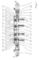
- the arrangement according to the invention comprises a switching device which has a switching shaft 1 for selecting and shifting desired gears, on which four shift rockers or shift forks 2, 3, 4, 5 are mounted by way of example, with which gears are connected in a known manner by an axial movement can be.
- the switching device comprises a selection device for rotating the switching shaft 1 and a switching device for axially displacing the switching shaft 1. Further, the switching device comprises a locking device for blocking and releasing the shift rockers / shift forks 2, 3, 4, 5.
- the switching device is formed in the proposed arrangement as a preassembled unit, since the switching device is constructed very compact, which in particular from FIG. 1 and 2 is apparent.
- the bearing device has a plurality of bearings 17 for supporting the switching shaft 1, wherein the bearings 17 are each mounted in bearing blocks 12 for receiving the central locking rail 18.
- the bearing blocks 12 are fixedly connected via fastening bolts 20 to a housing 19 of the switching device and to a selector housing 22 of the selector device and to a switch housing 23 of the switching device.
- the locking device comprises the central Rast Sammlungsschiene 18 and each of the individual shift rockers / shift forks 2, 3, 4, 5 associated Rastiergephaseuse 13 which are fastened with screws 16 to the respective shift rockers / shift forks 2, 3, 4, 5.
- Each Rastiergephaseuse 13 receives a locking pin 14 and a compression spring 15.
- Each compression spring 15 is supported on the one hand on the Rastiergephaseuse 13 and on a receiving portion of the locking bolt 14, as this particular FIG. 3 is apparent.
- the locking pin 14 is pressed or biased by a first end by means of the compression spring 15 against the peripheral portion of the switching shaft 1, wherein a second end of the respective locking pin 14 is disposed in an associated recess or groove 25 in the Rast michsschiene 18.
- transverse grooves 24 are provided to the main axis or longitudinal axis, which each have a shift rocker / shift fork 2, 3, 4, 5 are assigned.
- the transverse grooves 24 have a rotational offset, which is designed so that only one locking pin 14 can immerse in a transverse groove 24. This is especially true of the FIGS. 1 and 6 seen.
- the other locking pin 14 are pressed due to the non-existing transverse groove at this point the shift shaft 1 in the respective associated recess 25 of the central locking rail 18. This is especially true of the FIGS. 1 . 4 . 5 and 7 seen.
- any shift rocker / shift fork 2, 3, 4, 5 are selected in the switching device.
- the rotational movement is realized by the selector, which is assigned to a first end of the shift shaft 1.
- the selection device comprises a controllable rotary drive 6 with a drive shaft 26, the rotational movement of which is transmitted via a transmission stage 21 directly to the switching shaft 1.
- the second end of the switching shaft 1 is assigned to the switching device.
- the switching device also includes a controllable drive 7, which drives a spindle drive.
- the spindle drive comprises a spindle 9 and an axially movable spindle nut 8, which is secured against rotation by bolts 11 and connected to the switching shaft 1. Due to the axial movement of the spindle nut, the shift shaft 1 and the connected by the locking pin 14 or selected shift rocker / shift fork 4 is moved axially.
- damping packages 10 mounted.
- the damping packs 10 may also be provided at other positions.
- additional damping packages 10 are additionally used.
Landscapes
- Engineering & Computer Science (AREA)
- General Engineering & Computer Science (AREA)
- Mechanical Engineering (AREA)
- Gear-Shifting Mechanisms (AREA)
- Structure Of Transmissions (AREA)
Applications Claiming Priority (1)
| Application Number | Priority Date | Filing Date | Title |
|---|---|---|---|
| DE102008040207A DE102008040207A1 (de) | 2008-07-07 | 2008-07-07 | Anordnung zum Wählen und Schalten von Gängen bei einem Schaltgetriebe eines Fahrzeuges |
Publications (2)
| Publication Number | Publication Date |
|---|---|
| EP2143980A2 true EP2143980A2 (fr) | 2010-01-13 |
| EP2143980A3 EP2143980A3 (fr) | 2010-09-22 |
Family
ID=41136649
Family Applications (1)
| Application Number | Title | Priority Date | Filing Date |
|---|---|---|---|
| EP09163066A Ceased EP2143980A3 (fr) | 2008-07-07 | 2009-06-18 | Agencement destiné à sélectionner et à commuter des vitesses dans une boîte de vitesses d'un véhicule |
Country Status (2)
| Country | Link |
|---|---|
| EP (1) | EP2143980A3 (fr) |
| DE (1) | DE102008040207A1 (fr) |
Cited By (5)
| Publication number | Priority date | Publication date | Assignee | Title |
|---|---|---|---|---|
| WO2018220561A1 (fr) * | 2017-05-30 | 2018-12-06 | Ka Group Ag | Système de verrouillage de fourchette de débrayage de transmission |
| WO2020025282A1 (fr) * | 2018-07-30 | 2020-02-06 | Knorr-Bremse Systeme für Nutzfahrzeuge GmbH | Mécanisme de commutation pour transmission |
| CN112855912A (zh) * | 2020-12-30 | 2021-05-28 | 上汽通用五菱汽车股份有限公司 | 变速器选换档定排机构 |
| CN113217618A (zh) * | 2020-01-21 | 2021-08-06 | 克诺尔制动系统(大连)有限公司 | 用于传动机构的换档装置 |
| EP3770468A4 (fr) * | 2018-03-21 | 2021-10-20 | Weichai Power Co., Ltd. | Mécanisme et procédé de sélection de vitesse et de man uvre de changement de vitesse |
Citations (4)
| Publication number | Priority date | Publication date | Assignee | Title |
|---|---|---|---|---|
| US4425814A (en) * | 1981-03-23 | 1984-01-17 | Dana Corporation | Torque limiting device |
| US4498350A (en) * | 1982-09-20 | 1985-02-12 | Eaton Corporation | Shifting mechanism |
| DE4342957A1 (de) | 1993-12-16 | 1995-06-22 | Zahnradfabrik Friedrichshafen | Schaltvorrichtung |
| DE102004043116A1 (de) * | 2003-09-17 | 2005-04-21 | Luk Lamellen & Kupplungsbau | Kraftfahrzeuggetriebe-Stellvorrichtung |
Family Cites Families (9)
| Publication number | Priority date | Publication date | Assignee | Title |
|---|---|---|---|---|
| JPS58189716A (ja) * | 1982-04-28 | 1983-11-05 | Mitsubishi Motors Corp | ギヤシフト装置 |
| DE3827571A1 (de) * | 1988-08-13 | 1990-03-08 | Porsche Ag | Schaltvorrichtung fuer ein zahnraeder-wechselgetriebe eines kraftfahrzeugs |
| DE19530616C2 (de) * | 1995-08-21 | 1998-10-22 | Daimler Benz Ag | Schaltvorrichtung für Zahnräderwechselgetriebe |
| DE19756639A1 (de) * | 1997-12-19 | 1999-06-24 | Zahnradfabrik Friedrichshafen | Schalteinrichtung |
| DE19841153B4 (de) * | 1998-09-09 | 2008-04-03 | Zf Sachs Ag | Vorrichtung zur Anbindung eines rotierend und translatorisch antreibbaren Antribsteil einer Stelleinrichtung an eine Schaltwelle |
| DE10038524A1 (de) * | 2000-05-15 | 2001-11-22 | Daimler Chrysler Ag | Automatisches Getriebe |
| EP1162393A3 (fr) * | 2000-06-05 | 2004-04-28 | Eaton Corporation | Dispositif de changement de vitesses pour une transmission à commande manuelle avec un arbre de commande unique |
| DE10347492A1 (de) * | 2003-10-13 | 2005-06-09 | Zf Friedrichshafen Ag | Schalteinrichtung |
| DE102005028122A1 (de) * | 2005-06-10 | 2006-12-14 | Getrag Getriebe- Und Zahnradfabrik Hermann Hagenmeyer Gmbh & Cie Kg | Automatisiertes Vorgelegegetriebe und Verfahren zu dessen Herstellung |
-
2008
- 2008-07-07 DE DE102008040207A patent/DE102008040207A1/de not_active Withdrawn
-
2009
- 2009-06-18 EP EP09163066A patent/EP2143980A3/fr not_active Ceased
Patent Citations (4)
| Publication number | Priority date | Publication date | Assignee | Title |
|---|---|---|---|---|
| US4425814A (en) * | 1981-03-23 | 1984-01-17 | Dana Corporation | Torque limiting device |
| US4498350A (en) * | 1982-09-20 | 1985-02-12 | Eaton Corporation | Shifting mechanism |
| DE4342957A1 (de) | 1993-12-16 | 1995-06-22 | Zahnradfabrik Friedrichshafen | Schaltvorrichtung |
| DE102004043116A1 (de) * | 2003-09-17 | 2005-04-21 | Luk Lamellen & Kupplungsbau | Kraftfahrzeuggetriebe-Stellvorrichtung |
Cited By (6)
| Publication number | Priority date | Publication date | Assignee | Title |
|---|---|---|---|---|
| WO2018220561A1 (fr) * | 2017-05-30 | 2018-12-06 | Ka Group Ag | Système de verrouillage de fourchette de débrayage de transmission |
| EP3770468A4 (fr) * | 2018-03-21 | 2021-10-20 | Weichai Power Co., Ltd. | Mécanisme et procédé de sélection de vitesse et de man uvre de changement de vitesse |
| US11506283B2 (en) | 2018-03-21 | 2022-11-22 | Weichai Power Co., Ltd. | Gear selection and shifting actuating mechanism and method |
| WO2020025282A1 (fr) * | 2018-07-30 | 2020-02-06 | Knorr-Bremse Systeme für Nutzfahrzeuge GmbH | Mécanisme de commutation pour transmission |
| CN113217618A (zh) * | 2020-01-21 | 2021-08-06 | 克诺尔制动系统(大连)有限公司 | 用于传动机构的换档装置 |
| CN112855912A (zh) * | 2020-12-30 | 2021-05-28 | 上汽通用五菱汽车股份有限公司 | 变速器选换档定排机构 |
Also Published As
| Publication number | Publication date |
|---|---|
| EP2143980A3 (fr) | 2010-09-22 |
| DE102008040207A1 (de) | 2010-01-14 |
Similar Documents
| Publication | Publication Date | Title |
|---|---|---|
| EP1836419B1 (fr) | Dispositif de commutation pour boite de vitesses et utilisation d'un tel dispositif de commutation | |
| EP1836421B1 (fr) | Dispositif d'actionnement de fourchettes | |
| EP2342050B1 (fr) | Machine-outil manuelle équipée d'une transmission débrayable | |
| EP2143980A2 (fr) | Agencement destiné à sélectionner et à commuter des vitesses dans une boîte de vitesses d'un véhicule | |
| EP2206572B1 (fr) | Outil électrique doté d'un engrenage commutable | |
| DE19914198B4 (de) | Rückwärtsgang-Verriegelungsvorrichtung an einem Schaltgetriebe | |
| EP1711727B1 (fr) | Systeme de changement de vitesses | |
| EP1917462B1 (fr) | Dispositif de commutation pour deplacer une fourchette d'embrayage | |
| DE102008000643B4 (de) | Anordnung zum Schalten von zumindest einem Losrad an einer zugeordneten Welle eines Getriebes | |
| EP3339682A1 (fr) | Pignon baladeur pour un dispositif de boîte à pignons baladeurs | |
| WO2009015995A1 (fr) | Actionneur de boîte de vitesses pour actionner un dispositif de commutation d'une boîte de vitesses | |
| DE102011004063A1 (de) | Schaltsperre und Schaltvorrichtung mit einer Schaltsperre | |
| DE102012219085A1 (de) | Schaltvorrichtung eines Kraftfahrzeugwechselgetriebes | |
| WO2009112343A1 (fr) | Dispositif d'actionnement pour l'actionnement d'au moins un dispositif de couplage et procédé de montage et de démontage de celui-ci. | |
| EP1514764A2 (fr) | Unité de colonne de direction de véhicule automobile | |
| WO2005038309A1 (fr) | Dispositif de changement de vitesse | |
| EP1281895B1 (fr) | Mécanisme de verrouillage pour commande de changement de vitesse | |
| DE10254129B4 (de) | Elektromotorischer Möbelantrieb zum Verstellen von Teilen eines Möbels relativ zueinander | |
| EP1673560B1 (fr) | Dispositif de changement de vitesse | |
| DE102021134436B4 (de) | Aktorbaugruppe | |
| DE102019100300A1 (de) | Parksperraktuator | |
| DE10316444B4 (de) | Schaltmechanismus zum Durchführen von Schaltungen | |
| EP3649381B1 (fr) | Actionnement de changement de rapport pour une boîte de vitesses manuelle d'un véhicule automobile comprenant une masse accouplée par le biais d'une barre d'accouplement | |
| DE102017123826B4 (de) | Entkoppelte Schalteinheit | |
| DE102020201500A1 (de) | Wendegetriebeeinheit |
Legal Events
| Date | Code | Title | Description |
|---|---|---|---|
| PUAI | Public reference made under article 153(3) epc to a published international application that has entered the european phase |
Free format text: ORIGINAL CODE: 0009012 |
|
| AK | Designated contracting states |
Kind code of ref document: A2 Designated state(s): AT BE BG CH CY CZ DE DK EE ES FI FR GB GR HR HU IE IS IT LI LT LU LV MC MK MT NL NO PL PT RO SE SI SK TR |
|
| PUAL | Search report despatched |
Free format text: ORIGINAL CODE: 0009013 |
|
| AK | Designated contracting states |
Kind code of ref document: A3 Designated state(s): AT BE BG CH CY CZ DE DK EE ES FI FR GB GR HR HU IE IS IT LI LT LU LV MC MK MT NL NO PL PT RO SE SI SK TR |
|
| AX | Request for extension of the european patent |
Extension state: AL BA RS |
|
| 17P | Request for examination filed |
Effective date: 20110314 |
|
| 17Q | First examination report despatched |
Effective date: 20110411 |
|
| STAA | Information on the status of an ep patent application or granted ep patent |
Free format text: STATUS: THE APPLICATION HAS BEEN REFUSED |
|
| 18R | Application refused |
Effective date: 20120310 |