EP2143530A1 - Werkzeugmaschine - Google Patents
Werkzeugmaschine Download PDFInfo
- Publication number
- EP2143530A1 EP2143530A1 EP20090008781 EP09008781A EP2143530A1 EP 2143530 A1 EP2143530 A1 EP 2143530A1 EP 20090008781 EP20090008781 EP 20090008781 EP 09008781 A EP09008781 A EP 09008781A EP 2143530 A1 EP2143530 A1 EP 2143530A1
- Authority
- EP
- European Patent Office
- Prior art keywords
- tool
- axial direction
- dynamic vibration
- internal space
- tool bit
- Prior art date
- Legal status (The legal status is an assumption and is not a legal conclusion. Google has not performed a legal analysis and makes no representation as to the accuracy of the status listed.)
- Granted
Links
- 239000003638 chemical reducing agent Substances 0.000 claims abstract description 132
- 230000033001 locomotion Effects 0.000 claims abstract description 67
- 230000005540 biological transmission Effects 0.000 claims description 25
- 238000010276 construction Methods 0.000 description 19
- 230000001603 reducing effect Effects 0.000 description 8
- 238000000034 method Methods 0.000 description 6
- 230000007246 mechanism Effects 0.000 description 5
- 230000004048 modification Effects 0.000 description 4
- 238000012986 modification Methods 0.000 description 4
- 230000009471 action Effects 0.000 description 2
- 125000004122 cyclic group Chemical group 0.000 description 1
- 238000005553 drilling Methods 0.000 description 1
- 230000000694 effects Effects 0.000 description 1
- 238000009434 installation Methods 0.000 description 1
- 238000004519 manufacturing process Methods 0.000 description 1
- 230000009467 reduction Effects 0.000 description 1
Images


Classifications
-
- B—PERFORMING OPERATIONS; TRANSPORTING
- B25—HAND TOOLS; PORTABLE POWER-DRIVEN TOOLS; MANIPULATORS
- B25D—PERCUSSIVE TOOLS
- B25D17/00—Details of, or accessories for, portable power-driven percussive tools
- B25D17/24—Damping the reaction force
-
- B—PERFORMING OPERATIONS; TRANSPORTING
- B25—HAND TOOLS; PORTABLE POWER-DRIVEN TOOLS; MANIPULATORS
- B25D—PERCUSSIVE TOOLS
- B25D2211/00—Details of portable percussive tools with electromotor or other motor drive
- B25D2211/006—Parallel drill and motor spindles
-
- B—PERFORMING OPERATIONS; TRANSPORTING
- B25—HAND TOOLS; PORTABLE POWER-DRIVEN TOOLS; MANIPULATORS
- B25D—PERCUSSIVE TOOLS
- B25D2211/00—Details of portable percussive tools with electromotor or other motor drive
- B25D2211/06—Means for driving the impulse member
- B25D2211/061—Swash-plate actuated impulse-driving mechanisms
-
- B—PERFORMING OPERATIONS; TRANSPORTING
- B25—HAND TOOLS; PORTABLE POWER-DRIVEN TOOLS; MANIPULATORS
- B25D—PERCUSSIVE TOOLS
- B25D2217/00—Details of, or accessories for, portable power-driven percussive tools
- B25D2217/0073—Arrangements for damping of the reaction force
- B25D2217/0076—Arrangements for damping of the reaction force by use of counterweights
- B25D2217/0092—Arrangements for damping of the reaction force by use of counterweights being spring-mounted
-
- B—PERFORMING OPERATIONS; TRANSPORTING
- B25—HAND TOOLS; PORTABLE POWER-DRIVEN TOOLS; MANIPULATORS
- B25D—PERCUSSIVE TOOLS
- B25D2250/00—General details of portable percussive tools; Components used in portable percussive tools
- B25D2250/091—Electrically-powered tool components
- B25D2250/095—Electric motors
-
- B—PERFORMING OPERATIONS; TRANSPORTING
- B25—HAND TOOLS; PORTABLE POWER-DRIVEN TOOLS; MANIPULATORS
- B25D—PERCUSSIVE TOOLS
- B25D2250/00—General details of portable percussive tools; Components used in portable percussive tools
- B25D2250/245—Spatial arrangement of components of the tool relative to each other
-
- B—PERFORMING OPERATIONS; TRANSPORTING
- B25—HAND TOOLS; PORTABLE POWER-DRIVEN TOOLS; MANIPULATORS
- B25D—PERCUSSIVE TOOLS
- B25D2250/00—General details of portable percussive tools; Components used in portable percussive tools
- B25D2250/371—Use of springs
- B25D2250/381—Leaf springs
Definitions
- the present invention relates to a power tool having a dynamic vibration reducer.
- WO 2005-105386 A1 discloses an electric hammer having a dynamic vibration reducing section.
- the known electric hammer is provided with a dynamic vibration reducer for reducing vibration caused in the hammer in an axial direction of a hammer bit during hammering operation.
- the dynamic vibration reducer has a weight which can move linearly in the state in which the elastic biasing force of a coil spring is exerted on the weight, so that vibration of the hammer is reduced during hammering operation by the movement of the weight in the axial direction of the hammer bit.
- a power tool linearly drives a tool bit so as to cause the tool bit to perform a predetermined operation on a workpiece and includes at least a tool body, a driving motor, a motor output shaft, a motion converting section, an air spring chamber, a striking element, an internal space and a dynamic vibration reducer.
- the internal space is located to the motion converting section side of the driving motor within the body.
- An inner edge of the internal space is defined by an outer edge of the motion converting section, and an outer edge of the internal space is defined by an outer periphery of the driving motor.
- the dynamic vibration reducer includes a weight and an elastic member that elastically supports the weight with respect to the tool body.
- the weight elastically supported by the elastic member moves linearly in the axial direction of the tool bit against a spring force of the elastic member, so that vibration of the tool body is reduced during operation.
- the "linear movement of the weight" in this invention is not limited to linear movement in the axial direction of the tool bit, but it is only essential that the linear movement has at least components in the axial direction of the tool bit.
- the dynamic vibration reducer is disposed within the above-described internal space.
- the internal space is located to the motion converting section side of the driving motor within the body.
- a space around the motion converting section is likely to be rendered free, so that the inner edge of the internal space can be defined by the outer edge of the motion converting section.
- the outer edge of the internal space can be defined by the outer periphery of the motor. Therefore, by installing the dynamic vibration reducer within the internal space, rational placement of the dynamic vibration reducer can be realized without increasing the size of the tool body by effectively utilizing a free space within the tool body.
- the "placement of the dynamic vibration reducer within the internal space" may include the manner in which the dynamic vibration reducer is disposed within the internal space in its entirety or in part.
- the dynamic vibration reducer is placed within the internal space in a position displaced from a line connecting the swinging member and the driving element when viewed in a section of the tool body which is taken in a direction transverse to the axial direction of the tool bit.
- the elastic member is configured as a coil spring that elastically supports the weight.
- the weight has a spring receiving part that extends in a form of a hollow in the axial direction of the tool bit in at least one of front and rear portions of the weight and receives one end of the coil spring.
- a power tool linearly drives a tool bit so as to cause the tool bit to perform a predetermined operation on a workpiece and includes at least a tool body, a driving motor, a motor output shaft, a motion converting section, an air spring chamber, a striking element, a power transmitting section, an internal space and a dynamic vibration reducer.
- the tool body, the driving motor, the motor output shaft, the motion converting section, the air spring chamber, the striking element and the dynamic vibration reducer in this power tool have the same construction as the above-described tool body, driving motor, motor output shaft, motion converting section, air spring chamber, striking element and dynamic vibration reducer.
- the power transmitting section includes a holding element and a transmission gear.
- the holding element extends in the axial direction of the tool bit and holds the tool bit.
- the transmission gear rotates the holding element on its axis and thus rotationally drives the tool bit when the motor output shaft rotates.
- the internal space is located to the motion converting section side of the driving motor within the body. An inner edge of the internal space is defined by an outer edge of the motion converting section or an outer periphery of the driving motor, and an outer edge of the internal space is defined by an outer periphery of the transmission gear.
- the dynamic vibration reducer is disposed within this internal space.
- the internal space is located to the motion converting section side of the driving motor within the body.
- a space around the motion converting section is likely to be rendered free, so that the inner edge of the internal space can be defined by the outer edge of the motion converting section or the outer periphery of the driving motor.
- the outer edge of the internal space can be defined by the outer periphery of the transmission gear. Therefore, by installing the dynamic vibration reducer within the internal space, rational placement of the dynamic vibration reducer can be realized without increasing the size of the tool body by effectively utilizing a free space within the tool body.
- the dynamic vibration reducer is placed within the internal space in a position displaced to a tool upper region from the driving element when viewed in a section of the tool body which is taken in a direction transverse to the axial direction of the tool bit.
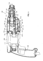
- FIG. 1 is a sectional side view showing an entire structure of a hammer drill 101 according to the first embodiment.
- FIG. 2 is part of a sectional side view of a different section of the hammer drill 101 shown in FIG. 1 .
- FIG. 3 is a sectional view of the hammer drill 101 taken along line A-A in FIG. 2 .
- the hammer drill 101 of the first embodiment mainly includes a body 103 that forms an outer shell of the hammer drill 101, a tool holder 137 connected to one end (right end as viewed in FIG. 1 ) of the body 103 in the longitudinal direction of the hammer drill 101, and a hammer bit 119 detachably coupled to the tool holder 137.
- the hammer bit 119 is held by the tool holder 137 such that it is allowed to reciprocate with respect to the tool holder in its axial direction (in the longitudinal direction of the body 103) and prevented from rotating with respect to the tool holder in its circumferential direction.
- the body 103 and the hammer bit 119 are features that correspond to the "tool body” and the "tool bit", respectively, according to the present invention.
- the body 103 includes a motor housing 105 that houses a driving motor 111, a gear housing 107 that houses a motion converting section 113 and a power transmitting section 114, a barrel part 117 that houses a striking mechanism 115, and a handgrip 109 designed to be held by a user and connected to the other end (left end as viewed in FIG. 1 ) of the body 103 in the longitudinal direction of the hammer drill 101.
- the side of the hammer bit 119 is taken as the front or tool front side and the side of the handgrip 109 as the rear or tool rear side.
- the motion converting section 113 serves to appropriately convert the rotating output of the driving motor 111 into linear motion and then transmit it to the striking mechanism 115. Then, a striking force (impact force) is generated in the axial direction of the hammer bit 119 via the striking mechanism 115.
- the power converting section 113 is a feature that corresponds to the "power converting section" according to this invention.
- the power converting section 113 mainly includes a driving gear 121, a driven gear 123, a rotating element 127, a swinging ring 129 and a cylinder 141.
- the driving gear 121 is connected to a motor output shaft 111a of the driving motor 111 that extends in the axial direction of the hammer bit 119, and rotationally driven when the driving motor 111 is driven.
- the driven gear 123 engages with the driving gear 121 and a driven shaft 125 is mounted to the driven gear 123. Therefore, the driven shaft 125 is connected to the motor output shaft 111a of the driving motor 111 and rotationally driven.
- the driving motor 111 and the motor output shaft 111a are features that correspond to the "driving motor” and the "motor output shaft", respectively, according to this invention.
- the rotating element 127 rotates together with the driven gear 123 via the driven shaft 125.
- the outer periphery of the rotating element 127 fitted onto the driven shaft 125 is inclined at a predetermined inclination with respect to the axis of the driven shaft 125.
- the swinging ring 129 is rotatably mounted on the inclined outer periphery of the rotating element 127 via a bearing 126 and caused to swing in the axial direction of the hammer bit 119 by rotation of the rotating element 127.
- the swinging ring 129 is a feature that corresponds to the "swinging member" according to this invention.
- the swinging ring 129 has a swinging rod 128 extending upward (in the radial direction) therefrom, and the swinging rod 128 is loosely engaged with an engagement member 124 formed on a rear end of the cylinder 141.
- the cylinder 141 is caused to reciprocate by swinging movement of the swinging ring 129 and serves as a driving element for driving the striking mechanism 115.
- An air spring chamber 141a is defined within the cylinder 141.
- the cylinder 141 and the air spring chamber 141a are features that correspond to the "driving element" and the "air spring chamber", respectively, according to this invention.
- the motor output shaft 111a of the driving motor 111, the driven shaft 125 and the driving element in the form of the cylinder 141 are arranged parallel to each other in the axial direction of the hammer bit 119.
- the driven shaft 125 is disposed below the motor output shaft 111a of the driving motor 111, and the cylinder 141 is disposed above the driven shaft 125.
- the power transmitting section 114 serves to appropriately reduce the speed of the rotating output of the driving motor 111 and rotate the hammer bit 119 in its circumferential direction.
- the power transmitting section 114 is disposed to the hammer bit 119 side of the driving motor 111 in the axial direction of the hammer bit 119.
- the power transmitting section 114 is a feature that corresponds to the "power transmitting section" according to this invention.
- the power transmitting section 114 mainly includes a first transmission gear 131, a second transmission gear 133 and the tool holder 137.
- the first transmission gear 131 is caused to rotate in a vertical plane by the driving motor 111 via the driving gear 121 and the driven shaft 125.
- the second transmission gear 133 is engaged with the first transmission gear 131 and rotates the tool holder 137 on its axis when the driven shaft 125 rotates.
- the tool holder 137 extends in the axial direction of the hammer bit 119 and serves as a holding element to hold the hammer bit 119, and it is rotated together with the second transmission gear 133.
- the second transmission gear 133 and the tool holder 137 are features that correspond to the "transmission gear" and the "holding element", respectively, according to this invention.
- the striking element 115 mainly includes a striker 143 slidably disposed within the bore of the cylinder 141, and an intermediate element in the form of an impact bolt 145 that is slidably disposed within the tool holder 137 and serves to transmit the kinetic energy of the striker 143 to the hammer bit 119.
- the striker 143 is formed as a striking element to strike the hammer bit 119 via the air spring chamber 141 a by the linear movement of the cylinder 141.
- the striker 143 is a feature that corresponds to the "striking element" according to this invention.
- the driving gear 121 is caused to rotate in a vertical plane by the rotating output of the driving motor.
- the rotating element 127 is caused to rotate in a vertical plane via the driven gear 123 engaged with the driving gear 121 and the driven shaft 125, which in turn causes the swinging ring 129 and the swinging rod 128 to swing in the axial direction of the hammer bit 119.
- the cylinder 141 is caused to linearly slide by the swinging movement of the swinging rod 128.
- the striker 143 By the action of the air spring function within the air spring chamber 141 a as a result of this sliding movement of the cylinder 141, the striker 143 linearly moves within the cylinder 141 at a speed faster than that of the linear movement of the cylinder 141. At this time, the striker 143 collides with the impact bolt 145 and transmits the kinetic energy caused by the collision to the hammer bit 119.
- the sleeve 135 When the first transmission gear 131 is caused to rotate together with the driven shaft 125, the sleeve 135 is caused to rotate in a vertical plane via the second transmission gear 133 that is engaged with the first transmission gear 131, which in turn causes the tool holder 137 and the hammer bit 119 held by the tool holder 137 to rotate in the circumferential direction together with the sleeve 135.
- the hammer bit 119 performs a hammering movement in the axial direction and a drilling movement in the circumferential direction, so that the hammer drill operation is performed on the workpiece.
- a dynamic vibration reducer 151 is provided to reduce impulsive and cyclic vibration caused in the body 103 when the hammer bit 119 is driven as described above.
- the dynamic vibration reducer 151 mainly includes a dynamic vibration reducer body 153, a weight 155 for vibration reduction, and coil springs 157 disposed on the tool front and rear sides of the weight 155 and extending in the axial direction of the hammer bit 119.
- the dynamic vibration reducer 151 is a feature that corresponds to the "dynamic vibration reducer" according to this embodiment.
- the dynamic vibration reducer body 153 has a housing space for housing the weight 155 and the coil springs 157 and is provided as a cylindrical guide for guiding the weight 155 to slide with stability.
- the dynamic vibration reducer body 153 is fixedly mounted to the body 103.
- the weight 155 is formed as a mass part which is slidably disposed within the housing space of the dynamic vibration reducer body 153 in such a manner as to move in the longitudinal direction of the housing space (in the axial direction of the hammer bit 119).
- the weight 155 is a feature that corresponds to the "weight” according to this embodiment.
- the weight 155 has spring receiving spaces 156 having a circular section and extending in the form of a hollow in the axial direction of the hammer bit 119 over a predetermined region in the front and rear portions of the weight 155.
- One end of each of the coil springs 157 is received in the associated spring receiving space 156.
- the spring receiving space 156 is a feature that corresponds to the "spring receiving part" according to this embodiment.
- first spring receiving spaces 156a receive the coil springs 157 disposed on the front of the weight 155
- second spring receiving spaces 156b receive the coil springs 157 disposed on the rear of the weight 155.
- the coil springs 157 are formed as elastic elements which support the weight 155 with respect to the dynamic vibration reducer body 153 or the body 103 such that the coil springs 157 exert respective spring forces on the weight 155 toward each other when the weight 155 moves within the housing space of the dynamic vibration reducer body 153 in the longitudinal direction (in the axial direction of the hammer bit 119). Further, preferably, the coil springs 157 received in the first spring receiving spaces 156a and the coil springs 157 received in the second spring receiving spaces 156b have the same spring constant.
- the coil spring 157 is a feature that corresponds to the "elastic member" and the "coil spring” according to this embodiment.
- a spring front end 157a is fixed on a spring front end fixing part 158 in the form of a front wall of the dynamic vibration reducer body 153, and a spring rear end 157b is fixed on a spring rear end fixing part 159 in the form of a bottom (end) of the first spring receiving spaces 156a.
- a spring front end 157a is fixed on a spring front end fixing part 158 in the form of a bottom (end) of the second spring receiving spaces 156b
- a spring rear end 157b is fixed on a spring rear end fixing part 159 in the form of a rear wall of the dynamic vibration reducer body 153.
- the front and rear coil springs 157 exert respective elastic biasing forces on the weight 155 toward each other in the axial direction of the hammer bit 119.
- the weight 155 can move in the axial direction of the hammer bit 119 in the state in which the elastic biasing forces of the front and rear coil springs 157 are exerted on the weight 155 toward each other in the axial direction of the hammer bit 119.
- the weight 155 and the coil springs 157 serve as vibration reducing elements in the dynamic vibration reducer 151 on the body 103 and cooperate to passively reduce vibration of the body 103 during operation of the hammer drill 101.
- the vibration of the body 103 in the hammer drill 101 can be alleviated or reduced during operation.
- the spring receiving spaces 156 are formed inside the weight 155 and one end of each of the coil springs 157 is disposed within the spring receiving space 156.
- the length of the dynamic vibration reducer 151 in the axial direction of the hammer bit 119 with the coil springs 157 received and set in the spring receiving spaces 156 of the weight 155 can be reduced, so that the size of the dynamic vibration reducer 151 can be reduced in the axial direction of the hammer bit 119.
- the first and second spring receiving spaces 156a, 156b of the spring receiving spaces 156 formed in the weight 155 are arranged to overlap each other. Accordingly, the coil springs 157 received within the first spring receiving spaces 156a and the coil springs 157 received within the second spring receiving spaces 156a are arranged to overlap each other in a direction transverse to the extending direction of the coil springs.
- the length of the weight 155 in the longitudinal direction with the coil springs 157 set in the spring receiving spaces 156 (156a, 156b) can be further reduced. Therefore, this construction is effective in further reducing the size of the dynamic vibration reducer 151 in its longitudinal direction and in reducing its weight with a simpler structure.
- this construction is particularly effective when installation space for the dynamic vibration reducer 151 in the body 103 is limited in the longitudinal direction of the body 103.
- the coil springs can be further upsized by the amount of the overlap between the coil springs 157 received within the first spring receiving spaces 156a and the coil springs 157 received within the second spring receiving spaces 156a, provided that the dynamic vibration reducer 151 having the same length in the longitudinal direction is used.
- the dynamic vibration reducer 151 can provide a higher vibration reducing effect by the upsized coil springs with stability.
- the above-mentioned effects of the dynamic vibration reducer 151 can also be obtained by dynamic vibration reducers 251, 351, 551 to 554, which will be described below.
- the dynamic vibration reducer 151 is placed in a left region (on the left side as viewed in FIG. 3 ) within the body 103 when the body 103 is viewed from the tool front (from the right as viewed in FIG. 2 ).
- the dynamic vibration reducer 151 having the above-described construction is disposed in an internal space 110 to the motion converting section 113 side of the driving motor 111 within the body 103.
- the inner edge of the internal space 110 is defined by the outer edge (the outer periphery) of the motion converting section 113 and the outer edge of the internal space 110 is defined by the outer periphery (shown by broken line in FIG. 3 ) of the driving motor 111.
- the internal space 110 is provided to one side of the motion converting section 113 and defined as a region which overlaps an area sectioned by the outer periphery of the driving motor 111 in the axial direction of the hammer bit 119.
- the internal space 110 is a feature that corresponds to the "internal space” according to this embodiment.
- the "placement of the dynamic vibration reducer 151 within the internal space" in this specification widely includes the manner in which the dynamic vibration reducer 151 is disposed within the internal space in its entirety or in part.
- a region around the motion converting section 113 is likely to be rendered free, so that the inner edge of the internal space 110 can be defined by the outer edge of the motion converting section 113.
- the outer edge of the internal space 110 can be defined by the outer periphery of the motor 111. Therefore, by installing the dynamic vibration reducer 151 within the internal space 110, rational placement of the dynamic vibration reducer 151 can be realized without increasing the size of the body 103 by effectively utilizing a free space within the body 103.
- the dynamic vibration reducer 151 is placed within the internal space 110 in a position displaced laterally to one side of a line connecting the swinging ring 129 and the driving element in the form of the cylinder 141 when viewed in a section of the body 103 which is taken along a direction transverse to the axial direction of the hammer bit 119. Therefore, within the internal space 110, particularly effective space for placement of the dynamic vibration reducer 151 can be utilized.
- This construction can be realized by appropriately changing the placement of component parts of the motion converting section 113 such that the internal space for the dynamic vibration reducer 151 can be ensured, for example, in a position displaced laterally to one side of a line connecting the swinging ring 129 and the cylinder 141.
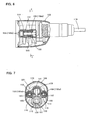
- FIG. 4 is part of a sectional side view of the hammer drill 101 according the second embodiment
- FIG. 5 is a sectional view of the hammer drill 101 taken along line B-B in FIG. 4 .
- components or elements which are substantially identical to those shown in FIGS. 1 to 3 are given like numerals.
- a dynamic vibration reducer 251 according to the second embodiment is one embodiment of the "dynamic vibration reducer" according to this invention.
- the dynamic vibration reducer 251 is placed in a left region (on the left side as viewed in FIG. 5 ) within the body 103 when the body 103 is viewed from the tool front (from the right as viewed in FIG. 4 ).
- the dynamic vibration reducer 251 is placed particularly by utilizing the internal space 110 described above in the first embodiment.
- the dynamic vibration reducer 251 is placed within the body 103 particularly by utilizing the internal space 110 which is defined by the motion converting section 113 and the outer periphery (shown by broken line in FIG.
- the internal space 110 is provided to one side of the motion converting section 113 and defined as a region which overlaps an area sectioned by the outer periphery of the driving motor 111 in the axial direction of the hammer bit 119.
- the dynamic vibration reducer 251 is placed within the internal space 110 in a position displaced laterally to one side of a line connecting the swinging ring 129 and the driving element in the form of the cylinder 141 when viewed in a section of the body 103 which is taken in a direction transverse to the axial direction of the hammer bit 119. Therefore, within the internal space 110, particularly effective space for placement of the dynamic vibration reducer 251 can be utilized.
- three spring receiving spaces 156 are arranged in a vertical direction transverse to the axial direction of the hammer bit 119.
- Two of the three spring receiving spaces 156 which are formed in the front portion of the weight 15 are referred to as first spring receiving spaces 156a, and the other one in the rear portion of the weight 155 (a left region of the weight 155 as viewed in FIG. 4 ) are referred to as a second spring receiving space 156b.
- the first spring receiving spaces 156a receive the coil springs 157 disposed on the front of the weight 155
- the second spring receiving spaces 156b receive the coil spring 157 disposed on the rear of the weight 155.
- the front and rear coil springs 157 exert respective elastic biasing forces on the weight 155 toward each other in the axial direction of the hammer bit 119.
- the weight 155 can move in the axial direction of the hammer bit 119 in the state in which the elastic biasing forces of the front and rear coil springs 157 are exerted on the weight 155 toward each other in the axial direction of the hammer bit 119.
- the sum of the spring constants of the two coil springs 157 received in the first spring receiving spaces 156a is equal to the spring constant of the coil spring 157 received in the second spring receiving space 156b.
- FIG. 6 is part of a sectional side view of the hammer drill 101 according the third embodiment
- FIG. 7 is a sectional view of the hammer drill 101 taken along line C-C in FIG. 6 .
- components or elements which are substantially identical to those shown in FIGS. 1 to 3 are given like numerals.
- a dynamic vibration reducer 351 is one embodiment of the "dynamic vibration reducer" according to this invention.
- the dynamic vibration reducer 351 is placed in right and left regions (on the right and left sides as viewed in FIG. 7 ) within the body 103.
- Two dynamic vibration reducers 351 are placed particularly by utilizing the internal space 110 described above in the first embodiment.
- the two dynamic vibration reducers 351 may also be considered as one integral dynamic vibration reducer 351.
- the dynamic vibration reducers 351 are placed within the body 103 particularly by utilizing the internal space 110 which is defined by the motion converting section 113 and the outer periphery (shown by broken line in FIG.
- the internal space 110 is provided to the both sides of the motion converting section 113 and defined as a region which overlaps an area sectioned by the outer periphery of the driving motor 111 in the axial direction of the hammer bit 119.
- the dynamic vibration reducers 351 are placed within the internal space 110 in a position displaced laterally to the both sides of a line connecting the swinging ring 129 and the driving element in the form of the cylinder 141 when viewed in a section of the body 103 which is taken in a direction transverse to the axial direction of the hammer bit 119. Therefore, within the internal space 110, particularly effective space for placement of the dynamic vibration reducers 351 can be utilized. Further, the two dynamic vibration reducers 351 are placed in a balanced manner on the right and left sides within the body 103.
- each of the dynamic vibration reducers 351 two spring receiving spaces 156 are arranged in a vertical direction transverse to the axial direction of the hammer bit 119.
- One of the two spring receiving spaces 156 which is formed in the front portion of the weight 155 (right region of the weight 155 as viewed in FIG. 6 ) is referred to as a first spring receiving space 156a
- the other one in the rear portion of the weight 155 (left region of the weight 155 as viewed in FIG. 6 ) is referred to as a second spring receiving space 156b.
- the first spring receiving space 156a receives the coil spring 157 disposed on the front of the weight 155
- the second spring receiving space 156b receives the coil spring 157 disposed on the rear of the weight 155.
- the front and rear coil springs 157 exert respective elastic biasing forces on the weight 155 toward each other in the axial direction of the hammer bit 119.
- the weight 155 can move in the axial direction of the hammer bit 119 in the state in which the elastic biasing forces of the front and rear coil springs 157 are exerted on the weight 155 toward each other in the axial direction of the hammer bit 119.
- the coil spring 157 received in the first spring receiving space 156a and the coil spring 157 received in the second spring receiving space 156b have the same spring constant.
- FIG. 8 is part of a sectional side view of the hammer drill 101 according the second embodiment
- FIG. 9 is a sectional view of the hammer drill 101 taken along line D-D in FIG. 8
- FIG. 10 shows a sectional structure similar to the structure shown in FIG. 9 .
- components or elements which are substantially identical to those shown in FIGS. 1 to 3 are given like numerals.
- a dynamic vibration reducer 451 according to the fourth embodiment is one embodiment of the "dynamic vibration reducer" according to this invention.
- the dynamic vibration reducer 451 is placed in a left region (on the left side as viewed in FIG. 8 ) within the body 103 when the body 103 is viewed from the tool front (from the right as viewed in FIG. 8 ).
- the dynamic vibration reducer 451 is placed particularly by utilizing the internal space 110 described above in the first embodiment.
- the dynamic vibration reducer 451 is placed within the body 103 particularly by utilizing the internal space 110 which is defined by the motion converting section 113 and the outer periphery (shown by broken line in FIG.
- the internal space 110 is provided to one side of the motion converting section 113 and defined as a region which overlaps an area sectioned by the outer periphery of the driving motor 111 in the axial direction of the hammer bit 119.
- the dynamic vibration reducer 451 is placed within the internal space 110 in a position displaced laterally to one side of a line connecting the swinging ring 129 and the driving element in the form of the cylinder 141 when viewed in a section of the body 103 which is taken in a direction transverse to the axial direction of the hammer bit 119. Therefore, within the internal space 110, particularly effective space for placement of the dynamic vibration reducer 451 can be utilized.
- the dynamic vibration reducer 451 mainly includes a weight 455 and a leaf spring 457.
- Spring end portions 457a, 457b on the both ends of the leaf spring 457 are mounted on a bracket 103a of the body 103 such that the leaf spring 457 is allowed to elastically deform in the axial direction of the hammer bit 119.
- the weight 455 is fixedly mounted on the middle of the leaf spring 457. The weight 455 can move in the axial direction of the hammer bit 119 in the state in which the elastic biasing force of the leaf spring 457 is exerted on the weight 455.
- the weight 455 and the leaf spring 457 serve as vibration reducing elements in the dynamic vibration reducer 451 on the body 103 and cooperate to passively reduce vibration of the body 103 during operation of the hammer drill 101.
- the weight 455 and the leaf spring 457 of the dynamic vibration reducer 451 are features that correspond to the "weight” and the "leaf spring", respectively, according to this invention.
- a plurality of dynamic vibration reducers identical or similar to the above-described dynamic vibration reducer 451 may be provided.
- right and left internal spaces 110 in right and left regions (on the right and left sides as viewed in FIG. 10 ) within the body 103 are utilized to place the dynamic vibration reducers 451 therein.
- two dynamic vibration reducers 451 are placed within the body 103 by utilizing the internal space 110 which is defined by the motion converting section 113 and the outer periphery (shown by broken line in FIG. 10 ) of the driving motor 111 in the axial direction of the hammer bit 119.
- the internal spaces 110 are provided to the both sides of the motion converting section 113 and defined as a region which overlaps an area sectioned by the outer periphery of the driving motor 111 in the axial direction of the hammer bit 119.
- the dynamic vibration reducers 451 are placed within the internal space 110 in a position displaced laterally to both sides of a line connecting the swinging ring 129 and the driving element in the form of the cylinder 141 when viewed in a section of the body 103 which is taken in a direction transverse to the axial direction of the hammer bit 119. Therefore, within the internal space 110, particularly effective space for placement of the dynamic vibration reducers 451 can be utilized. Further, the two dynamic vibration reducers 451 are placed in a balanced manner on the right and left sides within the body 103.
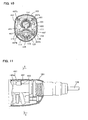
- FIGS. 11 and 12 A fifth embodiment of the power tool according to the present invention is now described with reference to FIGS. 11 and 12 .
- the fifth embodiment is a modification to the placement of the dynamic vibration reducer 451 of the fourth embodiment, and in the other points, it has the same construction as the above-described fourth embodiment.
- FIG. 11 is part of a sectional side view of the hammer drill 101 according the fifth embodiment
- FIG. 12 is a sectional view of the hammer drill 101 taken along line E-E in FIG. 11 .
- components or elements which are substantially identical to those shown in FIGS. 8 and 9 are given like numerals.
- the dynamic vibration reducer 451 is placed in a tool upper region (on the upper side as viewed in FIG. 12 ) within the body 103 and extends in the lateral direction of the body 103.
- the dynamic vibration reducer 45 is placed particularly by utilizing a second internal space 120 which is defined differently from the internal space 110 described above in the first embodiment.
- the dynamic vibration reducer 451 having the above-described construction is disposed in the second internal space 120.
- the second internal space 120 is a space located to the motion converting section 113 side of the driving motor 111 within the body 103.
- the inner edge of the internal space 120 is defined by the outer edge (outer periphery) of the motion converting section 113 or the outer periphery (shown by broken line in FIG. 12 ) of the driving motor 111, and the outer edge of the internal space 120 is defined by the outer periphery (shown by broken line in FIG. 12 ) of the second transmission gear 133.
- the internal space 120 is provided around the motion converting section 113 and defined as a region which overlaps an area sectioned by the outer periphery of the driving motor 111 or the outer periphery of the second transmission gear 133 in the axial direction of the hammer bit 119.
- the internal space 120 is a feature that corresponds to the "internal space" according to this embodiment.
- a tool upper region above the motion converting section 113 is likely to be rendered free, so that the inner edge of the internal space 120 can be defmed by the outer edge of the motion converting section 113 or the outer periphery of the second transmission gear 133.
- the outer edge of the internal space 120 can be defined by the outer periphery of the second transmission gear 133. Therefore, by utilizing the internal space 120 to install the dynamic vibration reducer 451, rational placement of the dynamic vibration reducer 451 can be realized by effectively utilizing a free space within the body 103 without increasing the size of the body 103.
- the dynamic vibration reducer 451 is placed within the internal space 120 in a position displaced to the tool upper region (on the upper side as viewed in FIG. 12 ) from the driving element in the form of the cylinder 141 when viewed in a section of the body 103 which is taken in a direction transverse to the axial direction of the hammer bit 119.
- the "tool upper region” here is typically defined as a region on the side of cylinder 141 opposite to the swinging ring 129 when viewed in a section of the body 103 which is taken in a direction transverse to the axial direction of the hammer bit 119. Therefore, within the internal space 120, particularly effective space for placement of the dynamic vibration reducer 451 can be utilized. This construction can be realized by appropriately changing the placement of component parts of the motion converting section 113 such that the internal space for the dynamic vibration reducer 451 can be ensured, for example, in a position displaced to the tool upper region from the cylinder 141.
- FIG. 13 is a sectional side view showing an entire structure of a hammer drill 201 according to another embodiment. Components or elements of the hammer drill 201 which are substantially identical to those of the hammer drill 101 shown in FIG. 1 are given like numerals.
- dynamic vibration reducers 551, 552 are placed in the tool upper and lower regions (on the upper and lower sides as viewed in FIG. 13 ) to the both upper and lower sides of the motion converting section 113 and the power transmitting section 114 within the body 103. Further, in the hammer drill 201, dynamic vibration reducers 553, 554 are placed in the tool upper and lower regions (on the upper and lower sides as viewed in FIG. 13 ) to the both upper and lower sides of the driving motor 111 within the body 103.
- the dynamic vibration reducers 551 to 554 are designed to passively reduce vibration by cooperation of the weight and the coil springs.
- the dynamic vibration reducers 551 to 554 are placed in the center in the lateral direction of the housing such that the respective weights are aligned with the center of the driven shaft 125 when viewed in a section of the housing which is taken in a direction transverse to the axial direction of the hammer bit 119.
- FIG. 13 for the sake of convenience, all of the dynamic vibration reducers 551 to 554 are shown provided within the body 103, but it is essential to provide at least one of the dynamic vibration reducers 551 to 554 within the body 103.
- One or more of the dynamic vibration reducers 551 to 554 can be provided within the body 103, as necessary.
- a housing upper portion may get in the way of performing an operation if it is bulged upward (to the upper side as viewed in FIG. 13 ). Accordingly, it is desired to design the housing upper portion to be bulged upward to the smallest possible extent. Therefore, after designing the housing upper portion to be bulged upward to the smallest possible extent, particularly, the dynamic vibration reducers 551 and 553 which are placed in the upper space within the body 103 are preferably arranged in a curved form along the housing wall surface, when viewed in a section of the housing which is taken in a direction transverse to the axial direction of the hammer bit 119.
- the housing lower portion is allowed to be bulged downward (to the lower side as viewed in FIG. 13 ) to such an extent as not to get in the way of operation.
- the dynamic vibration reducers 552 and 554 which are placed in the lower space within the body 103 have a greater freedom of placement compared with the dynamic vibration reducers 551 and 553.
- the front and rear portions of the weight are recessed to form the spring receiving spaces for receiving one end of the coil spring.
- it may be constructed, without providing the spring receiving spaces in the weight, such that one end of each of the coil springs is fixed on the front or rear end of the weight.
- the spring receiving spaces or fixing areas of the coil springs may be provided on at least one of the front and rear ends of the weight, as necessary.
- the hammer drill is described as a representative example of the power tool, but the present invention can also be applied to a hammer which linearly drives a tool bit to perform a predetermined operation, or other various kinds of power tools.
- all features disclosed in the description and/or the claims are intended to be disclosed separately and independently from each other for the purpose of original disclosure as well as for the purpose of restricting the claimed invention independent of the composition of the features in the embodiments and/or the claims.
- all value ranges or indications of groups of entities disclose every possible intermediate value or intermediate entity for the purpose of original disclosure as well as for the purpose of restricting the claimed invention, in particular as limits of value ranges.
Landscapes
- Engineering & Computer Science (AREA)
- Mechanical Engineering (AREA)
- Percussive Tools And Related Accessories (AREA)
Priority Applications (1)
| Application Number | Priority Date | Filing Date | Title |
|---|---|---|---|
| EP15178713.2A EP2962811B1 (de) | 2008-07-07 | 2009-07-03 | Elektrowerkzeug |
Applications Claiming Priority (1)
| Application Number | Priority Date | Filing Date | Title |
|---|---|---|---|
| JP2008177156A JP5336781B2 (ja) | 2008-07-07 | 2008-07-07 | 作業工具 |
Related Child Applications (2)
| Application Number | Title | Priority Date | Filing Date |
|---|---|---|---|
| EP15178713.2A Division-Into EP2962811B1 (de) | 2008-07-07 | 2009-07-03 | Elektrowerkzeug |
| EP15178713.2A Division EP2962811B1 (de) | 2008-07-07 | 2009-07-03 | Elektrowerkzeug |
Publications (2)
| Publication Number | Publication Date |
|---|---|
| EP2143530A1 true EP2143530A1 (de) | 2010-01-13 |
| EP2143530B1 EP2143530B1 (de) | 2015-09-16 |
Family
ID=41092035
Family Applications (2)
| Application Number | Title | Priority Date | Filing Date |
|---|---|---|---|
| EP09008781.8A Active EP2143530B1 (de) | 2008-07-07 | 2009-07-03 | Werkzeugmaschine |
| EP15178713.2A Active EP2962811B1 (de) | 2008-07-07 | 2009-07-03 | Elektrowerkzeug |
Family Applications After (1)
| Application Number | Title | Priority Date | Filing Date |
|---|---|---|---|
| EP15178713.2A Active EP2962811B1 (de) | 2008-07-07 | 2009-07-03 | Elektrowerkzeug |
Country Status (5)
| Country | Link |
|---|---|
| US (1) | US8347981B2 (de) |
| EP (2) | EP2143530B1 (de) |
| JP (1) | JP5336781B2 (de) |
| CN (1) | CN101623861A (de) |
| RU (1) | RU2496632C2 (de) |
Cited By (1)
| Publication number | Priority date | Publication date | Assignee | Title |
|---|---|---|---|---|
| EP2425937A1 (de) * | 2010-09-02 | 2012-03-07 | HILTI Aktiengesellschaft | Handwerkzeugmaschine |
Families Citing this family (18)
| Publication number | Priority date | Publication date | Assignee | Title |
|---|---|---|---|---|
| JP5336781B2 (ja) * | 2008-07-07 | 2013-11-06 | 株式会社マキタ | 作業工具 |
| JP5496812B2 (ja) * | 2010-08-03 | 2014-05-21 | 株式会社マキタ | 作業工具 |
| JP2013151055A (ja) * | 2012-01-26 | 2013-08-08 | Makita Corp | 打撃工具 |
| JP5857851B2 (ja) * | 2012-03-30 | 2016-02-10 | 日立工機株式会社 | 打撃工具 |
| JP6278830B2 (ja) * | 2014-05-16 | 2018-02-14 | 株式会社マキタ | 打撃工具 |
| RU2702181C2 (ru) * | 2014-11-12 | 2019-10-04 | Макита Корпорейшн | Бойковое устройство |
| CN105881463B (zh) * | 2015-02-15 | 2021-08-10 | 苏州宝时得电动工具有限公司 | 动力工具 |
| EP3208049B1 (de) * | 2016-02-19 | 2018-05-09 | Makita Corporation | Arbeitswerkzeug |
| US10814468B2 (en) | 2017-10-20 | 2020-10-27 | Milwaukee Electric Tool Corporation | Percussion tool |
| EP3511364A1 (de) | 2018-01-15 | 2019-07-17 | LANXESS Deutschland GmbH | Hr glasfasern in schwingbauteilen |
| EP3511365A1 (de) | 2018-01-15 | 2019-07-17 | LANXESS Deutschland GmbH | Hr glasfasern in schwingbauteilen |
| EP4349534A2 (de) | 2018-01-26 | 2024-04-10 | Milwaukee Electric Tool Corporation | Schlagwerkzeug |
| CN215617869U (zh) * | 2018-04-04 | 2022-01-25 | 米沃奇电动工具公司 | 一种适于向工具头施加轴向冲击的旋转锤 |
| JP7325530B2 (ja) * | 2019-11-19 | 2023-08-14 | 京セラインダストリアルツールズ株式会社 | 電動工具 |
| JP2022119301A (ja) * | 2021-02-04 | 2022-08-17 | 株式会社マキタ | 打撃工具 |
| JP2022128006A (ja) * | 2021-02-22 | 2022-09-01 | 株式会社マキタ | 打撃工具 |
| US11642769B2 (en) * | 2021-02-22 | 2023-05-09 | Makita Corporation | Power tool having a hammer mechanism |
| JP2022134644A (ja) * | 2021-03-03 | 2022-09-15 | 株式会社マキタ | 回転打撃工具 |
Citations (6)
| Publication number | Priority date | Publication date | Assignee | Title |
|---|---|---|---|---|
| US2875731A (en) * | 1956-03-23 | 1959-03-03 | Buckeye Steel Castings Co | Vibration absorbers for reciprocating tools |
| EP1415768A1 (de) * | 2002-10-31 | 2004-05-06 | Atlas Copco Electric Tools GmbH | Schwingungstilger |
| WO2005105386A1 (ja) | 2004-04-30 | 2005-11-10 | Makita Corporation | 作業工具 |
| GB2433909A (en) * | 2004-08-27 | 2007-07-11 | Makita Corp | Power tool with reciprocating vibration reducer |
| DE102006029363A1 (de) * | 2006-06-27 | 2008-01-03 | Robert Bosch Gmbh | Elektrohandwerkzeug |
| EP1892062A2 (de) * | 2006-08-24 | 2008-02-27 | Makita Corporation | Angetriebenes Schlagwerkzeug |
Family Cites Families (18)
| Publication number | Priority date | Publication date | Assignee | Title |
|---|---|---|---|---|
| US3845827A (en) * | 1971-08-05 | 1974-11-05 | Stihl Maschf Andreas | Portable implement,especially motor chain saw |
| DE3540964A1 (de) * | 1985-11-19 | 1987-05-21 | Bosch Gmbh Robert | Motorisch angetriebenes handwerkzeug fuer bohrenden oder schlagbohrenden betrieb |
| JP3843914B2 (ja) * | 2002-08-27 | 2006-11-08 | 松下電工株式会社 | ハンマードリル |
| JP4275930B2 (ja) * | 2002-11-07 | 2009-06-10 | 株式会社マキタ | 作業工具 |
| EP1464449B1 (de) * | 2003-04-01 | 2010-03-24 | Makita Corporation | Kraftwerkzeug |
| JP4647957B2 (ja) * | 2004-08-27 | 2011-03-09 | 株式会社マキタ | 作業工具 |
| JP4326452B2 (ja) * | 2004-10-26 | 2009-09-09 | パナソニック電工株式会社 | 衝撃工具 |
| US8261851B2 (en) * | 2005-04-11 | 2012-09-11 | Makita Corporation | Electric hammer |
| US7383895B2 (en) * | 2005-08-19 | 2008-06-10 | Makita Corporation | Impact power tool |
| JP4793755B2 (ja) | 2006-03-07 | 2011-10-12 | 日立工機株式会社 | 電動工具 |
| BRPI0707841A2 (pt) * | 2006-03-07 | 2011-05-10 | Hitachi Koki Kk | ferramenta elÉtrica |
| US8485274B2 (en) * | 2007-05-14 | 2013-07-16 | Makita Corporation | Impact tool |
| US7806201B2 (en) * | 2007-07-24 | 2010-10-05 | Makita Corporation | Power tool with dynamic vibration damping |
| US8196674B2 (en) * | 2008-03-05 | 2012-06-12 | Makita Corporation | Impact tool |
| JP5214343B2 (ja) * | 2008-06-19 | 2013-06-19 | 株式会社マキタ | 作業工具 |
| JP5336781B2 (ja) * | 2008-07-07 | 2013-11-06 | 株式会社マキタ | 作業工具 |
| JP5290666B2 (ja) * | 2008-08-29 | 2013-09-18 | 株式会社マキタ | 打撃工具 |
| JP5361504B2 (ja) * | 2009-04-10 | 2013-12-04 | 株式会社マキタ | 打撃工具 |
-
2008
- 2008-07-07 JP JP2008177156A patent/JP5336781B2/ja active Active
-
2009
- 2009-05-08 CN CN200910138197A patent/CN101623861A/zh active Pending
- 2009-06-30 US US12/458,062 patent/US8347981B2/en active Active
- 2009-07-03 EP EP09008781.8A patent/EP2143530B1/de active Active
- 2009-07-03 EP EP15178713.2A patent/EP2962811B1/de active Active
- 2009-07-06 RU RU2009125998/02A patent/RU2496632C2/ru active
Patent Citations (6)
| Publication number | Priority date | Publication date | Assignee | Title |
|---|---|---|---|---|
| US2875731A (en) * | 1956-03-23 | 1959-03-03 | Buckeye Steel Castings Co | Vibration absorbers for reciprocating tools |
| EP1415768A1 (de) * | 2002-10-31 | 2004-05-06 | Atlas Copco Electric Tools GmbH | Schwingungstilger |
| WO2005105386A1 (ja) | 2004-04-30 | 2005-11-10 | Makita Corporation | 作業工具 |
| GB2433909A (en) * | 2004-08-27 | 2007-07-11 | Makita Corp | Power tool with reciprocating vibration reducer |
| DE102006029363A1 (de) * | 2006-06-27 | 2008-01-03 | Robert Bosch Gmbh | Elektrohandwerkzeug |
| EP1892062A2 (de) * | 2006-08-24 | 2008-02-27 | Makita Corporation | Angetriebenes Schlagwerkzeug |
Cited By (2)
| Publication number | Priority date | Publication date | Assignee | Title |
|---|---|---|---|---|
| EP2425937A1 (de) * | 2010-09-02 | 2012-03-07 | HILTI Aktiengesellschaft | Handwerkzeugmaschine |
| US8985236B2 (en) | 2010-09-02 | 2015-03-24 | Hilti Aktiengesellschaft | Handheld power tool |
Also Published As
| Publication number | Publication date |
|---|---|
| RU2496632C2 (ru) | 2013-10-27 |
| US8347981B2 (en) | 2013-01-08 |
| EP2143530B1 (de) | 2015-09-16 |
| CN101623861A (zh) | 2010-01-13 |
| RU2009125998A (ru) | 2011-01-20 |
| JP2010012586A (ja) | 2010-01-21 |
| EP2962811A1 (de) | 2016-01-06 |
| JP5336781B2 (ja) | 2013-11-06 |
| US20100000751A1 (en) | 2010-01-07 |
| EP2962811B1 (de) | 2020-06-24 |
Similar Documents
| Publication | Publication Date | Title |
|---|---|---|
| EP2143530B1 (de) | Werkzeugmaschine | |
| EP2018939B1 (de) | Handwerkzeugmaschine mit Schwingungsdämpfer | |
| US7967078B2 (en) | Impact tool | |
| EP2540449B1 (de) | Angetriebenes Schlagwerkzeug | |
| EP1439038B1 (de) | Elektrischer Hammer | |
| US7604071B2 (en) | Power tool with vibration reducing means | |
| RU2507059C2 (ru) | Ручной приводной инструмент | |
| EP1754575B1 (de) | Angetriebenes Schlagwerkzeug | |
| RU2477211C2 (ru) | Ударный инструмент | |
| RU2606140C2 (ru) | Ударный инструмент | |
| RU2460633C2 (ru) | Инерционно-ударный инструмент | |
| EP2564986A2 (de) | Schlagwerkzeug | |
| EP1815946A1 (de) | Angetriebenes Schlagwerkzeug | |
| JP4793755B2 (ja) | 電動工具 | |
| RU2606139C2 (ru) | Приводной инструмент | |
| RU2531221C2 (ru) | Инструмент ударного действия | |
| JP2008307655A (ja) | 打撃工具 |
Legal Events
| Date | Code | Title | Description |
|---|---|---|---|
| PUAI | Public reference made under article 153(3) epc to a published international application that has entered the european phase |
Free format text: ORIGINAL CODE: 0009012 |
|
| AK | Designated contracting states |
Kind code of ref document: A1 Designated state(s): AT BE BG CH CY CZ DE DK EE ES FI FR GB GR HR HU IE IS IT LI LT LU LV MC MK MT NL NO PL PT RO SE SI SK SM TR |
|
| 17P | Request for examination filed |
Effective date: 20100702 |
|
| 17Q | First examination report despatched |
Effective date: 20130514 |
|
| GRAP | Despatch of communication of intention to grant a patent |
Free format text: ORIGINAL CODE: EPIDOSNIGR1 |
|
| INTG | Intention to grant announced |
Effective date: 20150407 |
|
| GRAS | Grant fee paid |
Free format text: ORIGINAL CODE: EPIDOSNIGR3 |
|
| GRAA | (expected) grant |
Free format text: ORIGINAL CODE: 0009210 |
|
| AK | Designated contracting states |
Kind code of ref document: B1 Designated state(s): AT BE BG CH CY CZ DE DK EE ES FI FR GB GR HR HU IE IS IT LI LT LU LV MC MK MT NL NO PL PT RO SE SI SK SM TR |
|
| REG | Reference to a national code |
Ref country code: GB Ref legal event code: FG4D |
|
| REG | Reference to a national code |
Ref country code: CH Ref legal event code: EP |
|
| REG | Reference to a national code |
Ref country code: IE Ref legal event code: FG4D |
|
| REG | Reference to a national code |
Ref country code: AT Ref legal event code: REF Ref document number: 749416 Country of ref document: AT Kind code of ref document: T Effective date: 20151015 |
|
| REG | Reference to a national code |
Ref country code: DE Ref legal event code: R096 Ref document number: 602009033622 Country of ref document: DE |
|
| REG | Reference to a national code |
Ref country code: NL Ref legal event code: MP Effective date: 20150916 |
|
| PG25 | Lapsed in a contracting state [announced via postgrant information from national office to epo] |
Ref country code: LT Free format text: LAPSE BECAUSE OF FAILURE TO SUBMIT A TRANSLATION OF THE DESCRIPTION OR TO PAY THE FEE WITHIN THE PRESCRIBED TIME-LIMIT Effective date: 20150916 Ref country code: GR Free format text: LAPSE BECAUSE OF FAILURE TO SUBMIT A TRANSLATION OF THE DESCRIPTION OR TO PAY THE FEE WITHIN THE PRESCRIBED TIME-LIMIT Effective date: 20151217 Ref country code: LV Free format text: LAPSE BECAUSE OF FAILURE TO SUBMIT A TRANSLATION OF THE DESCRIPTION OR TO PAY THE FEE WITHIN THE PRESCRIBED TIME-LIMIT Effective date: 20150916 Ref country code: NO Free format text: LAPSE BECAUSE OF FAILURE TO SUBMIT A TRANSLATION OF THE DESCRIPTION OR TO PAY THE FEE WITHIN THE PRESCRIBED TIME-LIMIT Effective date: 20151216 Ref country code: FI Free format text: LAPSE BECAUSE OF FAILURE TO SUBMIT A TRANSLATION OF THE DESCRIPTION OR TO PAY THE FEE WITHIN THE PRESCRIBED TIME-LIMIT Effective date: 20150916 |
|
| REG | Reference to a national code |
Ref country code: LT Ref legal event code: MG4D |
|
| REG | Reference to a national code |
Ref country code: AT Ref legal event code: MK05 Ref document number: 749416 Country of ref document: AT Kind code of ref document: T Effective date: 20150916 |
|
| PG25 | Lapsed in a contracting state [announced via postgrant information from national office to epo] |
Ref country code: HR Free format text: LAPSE BECAUSE OF FAILURE TO SUBMIT A TRANSLATION OF THE DESCRIPTION OR TO PAY THE FEE WITHIN THE PRESCRIBED TIME-LIMIT Effective date: 20150916 Ref country code: SE Free format text: LAPSE BECAUSE OF FAILURE TO SUBMIT A TRANSLATION OF THE DESCRIPTION OR TO PAY THE FEE WITHIN THE PRESCRIBED TIME-LIMIT Effective date: 20150916 |
|
| PG25 | Lapsed in a contracting state [announced via postgrant information from national office to epo] |
Ref country code: NL Free format text: LAPSE BECAUSE OF FAILURE TO SUBMIT A TRANSLATION OF THE DESCRIPTION OR TO PAY THE FEE WITHIN THE PRESCRIBED TIME-LIMIT Effective date: 20150916 |
|
| PG25 | Lapsed in a contracting state [announced via postgrant information from national office to epo] |
Ref country code: EE Free format text: LAPSE BECAUSE OF FAILURE TO SUBMIT A TRANSLATION OF THE DESCRIPTION OR TO PAY THE FEE WITHIN THE PRESCRIBED TIME-LIMIT Effective date: 20150916 Ref country code: IT Free format text: LAPSE BECAUSE OF FAILURE TO SUBMIT A TRANSLATION OF THE DESCRIPTION OR TO PAY THE FEE WITHIN THE PRESCRIBED TIME-LIMIT Effective date: 20150916 Ref country code: CZ Free format text: LAPSE BECAUSE OF FAILURE TO SUBMIT A TRANSLATION OF THE DESCRIPTION OR TO PAY THE FEE WITHIN THE PRESCRIBED TIME-LIMIT Effective date: 20150916 Ref country code: ES Free format text: LAPSE BECAUSE OF FAILURE TO SUBMIT A TRANSLATION OF THE DESCRIPTION OR TO PAY THE FEE WITHIN THE PRESCRIBED TIME-LIMIT Effective date: 20150916 Ref country code: SK Free format text: LAPSE BECAUSE OF FAILURE TO SUBMIT A TRANSLATION OF THE DESCRIPTION OR TO PAY THE FEE WITHIN THE PRESCRIBED TIME-LIMIT Effective date: 20150916 Ref country code: IS Free format text: LAPSE BECAUSE OF FAILURE TO SUBMIT A TRANSLATION OF THE DESCRIPTION OR TO PAY THE FEE WITHIN THE PRESCRIBED TIME-LIMIT Effective date: 20160116 |
|
| PG25 | Lapsed in a contracting state [announced via postgrant information from national office to epo] |
Ref country code: RO Free format text: LAPSE BECAUSE OF FAILURE TO SUBMIT A TRANSLATION OF THE DESCRIPTION OR TO PAY THE FEE WITHIN THE PRESCRIBED TIME-LIMIT Effective date: 20150916 Ref country code: PL Free format text: LAPSE BECAUSE OF FAILURE TO SUBMIT A TRANSLATION OF THE DESCRIPTION OR TO PAY THE FEE WITHIN THE PRESCRIBED TIME-LIMIT Effective date: 20150916 Ref country code: PT Free format text: LAPSE BECAUSE OF FAILURE TO SUBMIT A TRANSLATION OF THE DESCRIPTION OR TO PAY THE FEE WITHIN THE PRESCRIBED TIME-LIMIT Effective date: 20160118 Ref country code: AT Free format text: LAPSE BECAUSE OF FAILURE TO SUBMIT A TRANSLATION OF THE DESCRIPTION OR TO PAY THE FEE WITHIN THE PRESCRIBED TIME-LIMIT Effective date: 20150916 |
|
| REG | Reference to a national code |
Ref country code: DE Ref legal event code: R097 Ref document number: 602009033622 Country of ref document: DE |
|
| PLBE | No opposition filed within time limit |
Free format text: ORIGINAL CODE: 0009261 |
|
| REG | Reference to a national code |
Ref country code: FR Ref legal event code: PLFP Year of fee payment: 8 |
|
| STAA | Information on the status of an ep patent application or granted ep patent |
Free format text: STATUS: NO OPPOSITION FILED WITHIN TIME LIMIT |
|
| 26N | No opposition filed |
Effective date: 20160617 |
|
| PG25 | Lapsed in a contracting state [announced via postgrant information from national office to epo] |
Ref country code: DK Free format text: LAPSE BECAUSE OF FAILURE TO SUBMIT A TRANSLATION OF THE DESCRIPTION OR TO PAY THE FEE WITHIN THE PRESCRIBED TIME-LIMIT Effective date: 20150916 |
|
| PG25 | Lapsed in a contracting state [announced via postgrant information from national office to epo] |
Ref country code: SI Free format text: LAPSE BECAUSE OF FAILURE TO SUBMIT A TRANSLATION OF THE DESCRIPTION OR TO PAY THE FEE WITHIN THE PRESCRIBED TIME-LIMIT Effective date: 20150916 |
|
| PG25 | Lapsed in a contracting state [announced via postgrant information from national office to epo] |
Ref country code: BE Free format text: LAPSE BECAUSE OF FAILURE TO SUBMIT A TRANSLATION OF THE DESCRIPTION OR TO PAY THE FEE WITHIN THE PRESCRIBED TIME-LIMIT Effective date: 20150916 |
|
| REG | Reference to a national code |
Ref country code: CH Ref legal event code: PL |
|
| PG25 | Lapsed in a contracting state [announced via postgrant information from national office to epo] |
Ref country code: MC Free format text: LAPSE BECAUSE OF FAILURE TO SUBMIT A TRANSLATION OF THE DESCRIPTION OR TO PAY THE FEE WITHIN THE PRESCRIBED TIME-LIMIT Effective date: 20150916 |
|
| PG25 | Lapsed in a contracting state [announced via postgrant information from national office to epo] |
Ref country code: LI Free format text: LAPSE BECAUSE OF NON-PAYMENT OF DUE FEES Effective date: 20160731 Ref country code: CH Free format text: LAPSE BECAUSE OF NON-PAYMENT OF DUE FEES Effective date: 20160731 |
|
| REG | Reference to a national code |
Ref country code: IE Ref legal event code: MM4A |
|
| REG | Reference to a national code |
Ref country code: FR Ref legal event code: PLFP Year of fee payment: 9 |
|
| PG25 | Lapsed in a contracting state [announced via postgrant information from national office to epo] |
Ref country code: IE Free format text: LAPSE BECAUSE OF NON-PAYMENT OF DUE FEES Effective date: 20160703 |
|
| PG25 | Lapsed in a contracting state [announced via postgrant information from national office to epo] |
Ref country code: LU Free format text: LAPSE BECAUSE OF NON-PAYMENT OF DUE FEES Effective date: 20160703 |
|
| PG25 | Lapsed in a contracting state [announced via postgrant information from national office to epo] |
Ref country code: CY Free format text: LAPSE BECAUSE OF FAILURE TO SUBMIT A TRANSLATION OF THE DESCRIPTION OR TO PAY THE FEE WITHIN THE PRESCRIBED TIME-LIMIT Effective date: 20150916 Ref country code: SM Free format text: LAPSE BECAUSE OF FAILURE TO SUBMIT A TRANSLATION OF THE DESCRIPTION OR TO PAY THE FEE WITHIN THE PRESCRIBED TIME-LIMIT Effective date: 20150916 Ref country code: HU Free format text: LAPSE BECAUSE OF FAILURE TO SUBMIT A TRANSLATION OF THE DESCRIPTION OR TO PAY THE FEE WITHIN THE PRESCRIBED TIME-LIMIT; INVALID AB INITIO Effective date: 20090703 |
|
| REG | Reference to a national code |
Ref country code: FR Ref legal event code: PLFP Year of fee payment: 10 |
|
| PG25 | Lapsed in a contracting state [announced via postgrant information from national office to epo] |
Ref country code: TR Free format text: LAPSE BECAUSE OF FAILURE TO SUBMIT A TRANSLATION OF THE DESCRIPTION OR TO PAY THE FEE WITHIN THE PRESCRIBED TIME-LIMIT Effective date: 20150916 Ref country code: MK Free format text: LAPSE BECAUSE OF FAILURE TO SUBMIT A TRANSLATION OF THE DESCRIPTION OR TO PAY THE FEE WITHIN THE PRESCRIBED TIME-LIMIT Effective date: 20150916 Ref country code: MT Free format text: LAPSE BECAUSE OF NON-PAYMENT OF DUE FEES Effective date: 20160731 |
|
| PG25 | Lapsed in a contracting state [announced via postgrant information from national office to epo] |
Ref country code: BG Free format text: LAPSE BECAUSE OF FAILURE TO SUBMIT A TRANSLATION OF THE DESCRIPTION OR TO PAY THE FEE WITHIN THE PRESCRIBED TIME-LIMIT Effective date: 20150916 |
|
| PGFP | Annual fee paid to national office [announced via postgrant information from national office to epo] |
Ref country code: FR Payment date: 20230620 Year of fee payment: 15 |
|
| PGFP | Annual fee paid to national office [announced via postgrant information from national office to epo] |
Ref country code: GB Payment date: 20230601 Year of fee payment: 15 |
|
| PGFP | Annual fee paid to national office [announced via postgrant information from national office to epo] |
Ref country code: DE Payment date: 20230531 Year of fee payment: 15 |