EP2142391B1 - Wankstabilisator für ein kraftfahrzeug sowie gehäuse für den wankstabilisator - Google Patents
Wankstabilisator für ein kraftfahrzeug sowie gehäuse für den wankstabilisator Download PDFInfo
- Publication number
- EP2142391B1 EP2142391B1 EP08749579A EP08749579A EP2142391B1 EP 2142391 B1 EP2142391 B1 EP 2142391B1 EP 08749579 A EP08749579 A EP 08749579A EP 08749579 A EP08749579 A EP 08749579A EP 2142391 B1 EP2142391 B1 EP 2142391B1
- Authority
- EP
- European Patent Office
- Prior art keywords
- roll bar
- housing
- transmission
- stabilizer
- electric motor
- Prior art date
- Legal status (The legal status is an assumption and is not a legal conclusion. Google has not performed a legal analysis and makes no representation as to the accuracy of the status listed.)
- Not-in-force
Links
- 230000005540 biological transmission Effects 0.000 claims abstract description 37
- 230000033001 locomotion Effects 0.000 claims abstract description 15
- 239000003381 stabilizer Substances 0.000 claims description 104
- 230000000903 blocking effect Effects 0.000 claims description 3
- 238000009434 installation Methods 0.000 claims 2
- 230000000087 stabilizing effect Effects 0.000 abstract 4
- 230000006835 compression Effects 0.000 description 2
- 238000007906 compression Methods 0.000 description 2
- 230000001419 dependent effect Effects 0.000 description 2
- 238000007654 immersion Methods 0.000 description 2
- 230000001105 regulatory effect Effects 0.000 description 2
- 238000005096 rolling process Methods 0.000 description 2
- 230000004888 barrier function Effects 0.000 description 1
- 238000013016 damping Methods 0.000 description 1
- 238000006073 displacement reaction Methods 0.000 description 1
- 230000000694 effects Effects 0.000 description 1
- 238000004904 shortening Methods 0.000 description 1
- 239000000725 suspension Substances 0.000 description 1
Images
Classifications
-
- B—PERFORMING OPERATIONS; TRANSPORTING
- B60—VEHICLES IN GENERAL
- B60G—VEHICLE SUSPENSION ARRANGEMENTS
- B60G21/00—Interconnection systems for two or more resiliently-suspended wheels, e.g. for stabilising a vehicle body with respect to acceleration, deceleration or centrifugal forces
- B60G21/02—Interconnection systems for two or more resiliently-suspended wheels, e.g. for stabilising a vehicle body with respect to acceleration, deceleration or centrifugal forces permanently interconnected
- B60G21/04—Interconnection systems for two or more resiliently-suspended wheels, e.g. for stabilising a vehicle body with respect to acceleration, deceleration or centrifugal forces permanently interconnected mechanically
- B60G21/05—Interconnection systems for two or more resiliently-suspended wheels, e.g. for stabilising a vehicle body with respect to acceleration, deceleration or centrifugal forces permanently interconnected mechanically between wheels on the same axle but on different sides of the vehicle, i.e. the left and right wheel suspensions being interconnected
- B60G21/055—Stabiliser bars
- B60G21/0551—Mounting means therefor
- B60G21/0553—Mounting means therefor adjustable
- B60G21/0555—Mounting means therefor adjustable including an actuator inducing vehicle roll
-
- B—PERFORMING OPERATIONS; TRANSPORTING
- B60—VEHICLES IN GENERAL
- B60G—VEHICLE SUSPENSION ARRANGEMENTS
- B60G2202/00—Indexing codes relating to the type of spring, damper or actuator
- B60G2202/10—Type of spring
- B60G2202/13—Torsion spring
- B60G2202/135—Stabiliser bar and/or tube
-
- B—PERFORMING OPERATIONS; TRANSPORTING
- B60—VEHICLES IN GENERAL
- B60G—VEHICLE SUSPENSION ARRANGEMENTS
- B60G2202/00—Indexing codes relating to the type of spring, damper or actuator
- B60G2202/40—Type of actuator
- B60G2202/42—Electric actuator
-
- B—PERFORMING OPERATIONS; TRANSPORTING
- B60—VEHICLES IN GENERAL
- B60G—VEHICLE SUSPENSION ARRANGEMENTS
- B60G2204/00—Indexing codes related to suspensions per se or to auxiliary parts
- B60G2204/10—Mounting of suspension elements
- B60G2204/12—Mounting of springs or dampers
- B60G2204/122—Mounting of torsion springs
- B60G2204/1222—Middle mounts of stabiliser on vehicle body or chassis
Definitions
- the invention relates to a roll stabilizer for a motor vehicle with a first and a second stabilizer part, which are each assigned to a wheel of a common vehicle transverse axis of the motor vehicle and / or associated with a housing which is designed for a motor vehicle fixed mounting and in which the two stabilizer parts for Implementation of the same direction and opposite directions pivoting movements are stored, and with an actuator device which comprises an electric motor and a transmission gear, wherein the electric motor for generating a torque and the transmission gear for continuing the torque to the stabilizer parts are formed and a corresponding housing of the roll stabilizer.
- Such active roll stabilizers are used in motor vehicles to u. a. to compensate for the unevenly distributed immersion movements of the wheels of a vehicle transverse axis of the motor vehicle. Such uneven plunging movements take place, for example, in cornering of the motor vehicle, wherein the outside wheel of a vehicle transverse axis of the motor vehicle dips deeper than the inside wheel.
- an active roll stabilizer therefore, the lateral inclination of the motor vehicle is controlled by bracing the stabilizer parts against each other.
- passive roll stabilizers is a different immersion behavior of the wheels of a vehicle transverse axis by a Torsion of a torsion portion of the usually integrally formed roll stabilizer compensated.
- the torsion section of the passive roll stabilizers extends almost over a large part of the entire vehicle width.
- the stabilizer parts of a conventional active roll stabilizer are connected to each other via a joint or a gear, so that form two separate, each one of the two stabilizer parts associated Torsionsabête.
- the actuator of the active roll stabilizer which is formed from the electric motor and optionally the compensation arrangement, is usually arranged between the stabilizer parts, which leads to a further reduction of the space of the stabilizer parts and thus to a shortening of the Torsionsabitese.
- These torsion sections are greatly shortened in comparison to the torsion section of the passive roll stabilizer, so that for an application-oriented design of the torsion sections, these must be designed with a significantly harder torsion spring rate.
- the publication JP 8085328 proposes a storage control system for vehicles, with two stabilizers are driven by a spur gear by an electric motor, the spur gear only allows counter-rotation of the stabilizers, but not in the same direction by design. At a common compression of the wheels of a common vehicle transverse axis, the storage control system seems to block.
- the publication DE 102 33 499 A1 which is probably the closest prior art, describes a split, active motor vehicle stabilizer with two stabilizer parts and with an actuator for roll control, wherein the actuator has a device for torque output and a device for generating torque, wherein at least the device for generating torque outside the gap of the two stabilizer parts is arranged.
- the invention has for its object to provide a roll stabilizer for a motor vehicle and a corresponding housing for the roll stabilizer, with which an improved dynamic behavior of the roll stabilizer can be achieved.
- a roll stabilizer in particular an active roll stabilizer, is proposed for a motor vehicle which has a first and a second stabilizer part which can each be assigned and / or assigned to a wheel of a common vehicle transverse axis of the motor vehicle.
- the stabilizer parts may comprise torsion sections and in particular extend as far as the assigned wheel or up to a suspension of the wheel or be designed as mechanical interfaces for receiving stabilizers with torsion sections.
- the roll stabilizer can - depending on the embodiment - be designed for a front or a rear axle of a motor vehicle.
- It comprises a fixed and / or rigidly attachable in or on the motor vehicle housing, in which the two stabilizer parts are mounted so pivotable about a particular common pivot axis that they can perform the same direction and opposite directions pivoting movements.
- the same direction pivoting movements are used, for example, in a common compression of the stabilized wheels of a common transverse vehicle axis, the opposing pivoting movements are used for the selective distribution of torques on the two stabilizer parts.
- the roll stabilizer on an actuator device which comprises an electric motor, a transmission gear and - optionally - a compensation arrangement.
- the electric motor is provided for generating a torque which is transmitted via the transmission gear to the stabilizer parts or to the optional compensation arrangement and then delivered and / or distributed via the compensation arrangement on the stabilizer parts.
- the compensation arrangement is designed as a gear, which connects the two or the two stabilizer parts with each other and / or rotated against each other.
- the electric motor is independent of the or the pivoting movements of the stabilizer parts and in particular mounted in the vehicle-mounted, so stored stationary in or on the motor vehicle.
- the stabilizer parts can also pivot together and in the same direction in the housing, but without the common pivoting carry the electric motor, since this in contrast to the known prior art independently, in particular motor vehicle - possibly sprung or damped - arranged is.
- An advantage resulting from this arrangement is that the unsprung mass entrained during pivoting movements of the stabilizer parts is reduced, since the electric motor is mounted uncoupled from this pivot system and is therefore not moved or oscillated from its storage position in the case of torsions or torsions of the wheel. Due to the reduction in unsprung mass, the dynamic behavior which is forcibly coupled to the mass of the pivot system is improved.
- the electric motor is designed for a motor vehicle-fixed mounting and / or rigidly arranged relative to and / or on or in the housing.
- the electric motor is outside of one Interspace between the two stabilizer parts, eg offset in axial direction, arranged.
- the electric motor does not engage or overlap with it by an imaginary extension of the pivot axis and / or one of the torsion axes of the torsion sections of the stabilizer parts.
- the space between the stabilizer parts can be used for an extension of the torsion sections, so that the disadvantages of the shortened torsion sections discussed in the introduction are at least mitigated.
- it is achieved by the displacement of the electric motor from the intermediate space that standard motors can be used instead of special motors otherwise necessary.
- the stabilizer parts are pivotally mounted in the housing about a common pivot and / or torsion axis, wherein it is particularly provided that the Torsionsabroughe coaxial to the common axis of torsion and also to the common pivot axis.
- the electric motor can be aligned arbitrarily within the scope of the invention.
- the motor shaft so the output shaft of the electric motor is aligned parallel to the pivot axis and / or one of the torsion axes of the two stabilizer parts and / or the common torsion axis.
- This axially parallel arrangement of the electric motor allows a particularly space-saving implementation of the invention.
- the output shaft can also be aligned perpendicular to the pivot axis or torsion axis.
- the transmission gear is preferably designed as a belt transmission, spur gear, worm gear or belt transmission.
- the transmission gear already has a translation which is used to translate the relatively low engine torque of the electric motor, whereby the transmission ratio of an optionally downstream transmission gear can be made smaller. This design takes into account the fact that in general electric motors are high Speed, but produce a low engine torque.
- the optional compensation arrangement is arranged between the stabilizer parts.
- the compensation arrangement is arranged coaxially to the common pivot axis, the common torsion axis and / or in the intermediate space between the stabilizer parts. At this position, the torque transmission to the stabilizer parts can be carried out particularly effective and space-saving, whereas the electric motor is preferably outsourced from the coaxial region.
- the optional compensation arrangement has a transmission gear, which is preferably designed as a planetary gear, in particular as a two-stage planetary gear, and a compensation gear, which is formed, the torque in a relative pivoting of the stabilizer parts to each other about the pivot axis and / or to implement the torsion axis, and is realized, for example, as a cam gear.
- the transmission gear is used to translate after the transmission gear still relatively low engine torque, for example, a gear ratio in the range of 1:50 is realized.
- the transmission gear may also have a pivot angle dependent gear ratio.
- the first of the stabilizer parts is pivotally connected to a transmission gear housing and a compensation device housing and forms with these components a first assembly which is pivotally mounted in the housing.
- the second stabilizer part is preferably mounted in the first subassembly in the sense of an output shaft, so that the second stabilizer part is mounted in the housing via the first subassembly. In operation, a relative rotation of the first assembly leads to the second stabilizer part to a force acting on the vehicle longitudinal axis torque to compensate for rolling movements.
- the roll stabilizer optionally has a blocking device, also called a fail-safe device, which is designed to block a relative pivoting of the stabilizer parts relative to each other, for example in the event of a power failure.
- This blocking device may be provided, for example, as an integrated brake or lock in the electric motor.
- the transmission gear has such an integrated barrier.
- Another optional disposition position for the lock can be provided in the transmission gear, in particular in the belt transmission.
- Another object of the invention relates to a housing formed for the roll stabilizer according to one of the preceding claims or as just described, wherein the housing has a mechanical interface for rigid attachment of the housing to the motor vehicle, a motor mount, e.g. a mounting flange, for receiving the electric motor, and a storage device, in particular a rolling or sliding bearing for pivotally receiving the stabilizer parts, in particular for pivotally receiving the first assembly.
- a motor mount e.g. a mounting flange
- a storage device in particular a rolling or sliding bearing for pivotally receiving the stabilizer parts, in particular for pivotally receiving the first assembly.
- the housing and / or the roll stabilizer is formed, so that the stabilizer parts are mounted only in the housing via the bearing device and no further stabilizer bearings are provided up to the interfaces on the wheels. Due to the structure of the roll stabilizer, the storage device is optionally arranged asymmetrically to the wheels.
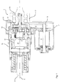
- FIG. 1 shows a schematic sectional view of a roll stabilizer 1 for a motor vehicle as an embodiment of the invention.
- the roll stabilizer 1 is designed to pivotally couple two stabilizers to each other, wherein in the FIG. 1 on the left side only the receptacle 2 for the one stabilizer and on the right side a flange 3 for attachment of the second stabilizer is shown.
- the two stabilizers each have a torsion portion, which are arranged to perform a torsion about a major axis 4, which thus forms the common torsion axis.
- the roll stabilizer 1 has a housing 5, which is firmly connected to the motor vehicle.
- conventional damping elements between housing 5 and motor vehicle are provided to rattle in operation or the like to avoid.
- the housing 5 points to its in FIG. 1 Right side shown on a double-row roller bearing 6, which is aligned coaxially with the main axis 4 and the flange 3 and thus the right stabilizer in the housing 5 superimposed.
- an outer ring with an outer running surface of the roller bearing 6 is integrally formed on the housing 5.
- the housing 5 has a motor flange 7 to which an electric motor 8 is flanged, wherein the electric motor 8 or its output shaft relative to the main axis 4 is offset in parallel and arranged without overlap.
- the electric motor 8 serves to generate a torque, which is used to pivot the two stabilizers against each other about the main axis, which then forms at the same time a pivot axis, so that the stabilizers are braced against each other.
- this is arranged relative to the housing 5 and thus relative to the motor vehicle rigid or fixed.
- the torque generated by the electric motor 8 is transmitted via a belt 9 in the housing 5.
- the belt 9 is part of a belt drive with a driven gear 10 and a drive wheel 11, wherein the diameter of the driven gear 10 is selected smaller than the diameter of the drive wheel 11. By the selected diameter ratio, the torque of the electric motor 8 is translated.
- the drive wheel 11 is coaxial with the sun gear of a two-stage planetary gear 12, which is designed as a downstream transmission gear, arranged, wherein the planetary gear 12 is mounted in a planetary gear housing 13.
- the torque is transmitted to a compensation gear 14, which is designed for example as a curved path gear.
- the cam gear sets the torque in a relative pivoting between a coaxially arranged inner part 15th and the inner part 15 concentrically surrounding Kompensationsgetriebegephaseuse 16 around.
- the inner part 15 is rotatably connected to the receptacle 2 for the left stabilizer.
- the relatively pivoting compensating gear housing 16 is non-rotatably connected via the planetary gear housing 13 to the flange 3 for the right stabilizer.
- the described Relativverschwenkung thus leads to a relative pivoting between the left and the right stabilizer, so that a tension between them by the electric motor 8 is controlled specifically.
- the roll stabilizer 1 due to the fixed chassis mounting of the electric motor 1 has the advantage that in a common pivoting of the stabilizers, the electric motor 8 is not pivoted, but only the output shaft is rotated.
- this joint pivoting of the stabilizers is formed by the downstream planetary gear 12 and the transmission gear, which together form a gear ratio of z. B. 1:50, with a maximum deflection of the wheels or the chassis and a maximum pivoting between the stabilizers and the stationary mounted in the motor vehicle housing 5 of about 25 ° mutual pivoting of the stabilizers to each other by about 0.5 ° , wherein this relative pivoting can be neglected.
- this pivoting can be actively regulated or controlled by control electronics.
Landscapes
- Engineering & Computer Science (AREA)
- Mechanical Engineering (AREA)
- Vehicle Body Suspensions (AREA)
- Transition And Organic Metals Composition Catalysts For Addition Polymerization (AREA)
Description
- Die Erfindung betrifft einen Wankstabilisator für ein Kraftfahrzeug mit einem ersten und einem zweiten Stabilisatorteil, welche jeweils einem Rad einer gemeinsamen Fahrzeugquerachse des Kraftfahrzeugs zuordbar und/oder zugeordnet sind, mit einem Gehäuse, welches für eine kraftfahrzeugfeste Montage ausgebildet ist und in dem die zwei Stabilisatorteile zur Durchführung von gleichsinnigen und gegensinnigen Schwenkbewegungen gelagert sind, und mit einer Aktuatorvorrichtung, welche einen Elektromotor und ein Übertragungsgetriebe umfasst, wobei der Elektromotor zur Erzeugung eines Drehmoments und das Übertragungsgetriebe zur Weiterführung des Drehmoments an die Stabilisatorteile ausgebildet sind sowie ein entsprechendes Gehäuse des Wankstabilisators.
- Derartige aktive Wankstabilisatoren werden in Kraftfahrzeugen eingesetzt, um u. a. die ungleichmäßig verteilten Eintauchbewegungen der Räder einer Fahrzeugquerachse des Kraftfahrzeuges zu kompensieren. Derartige ungleichmäßige Eintauchbewegungen erfolgen beispielsweise in Kurvenfahrten des Kraftfahrzeuges, wobei das kurvenäußere Rad einer Fahrzeugquerachse des Kraftfahrzeuges tiefer eintaucht als das kurveninnere Rad. Durch die Verwendung eines aktiven Wankstabilisators wird demnach die Seitenneigung des Kraftfahrzeuges durch Verspannen der Stabilisatorteile gegeneinander gesteuert.
- Bei konventionell verwendeten, passiven Wankstabilisatoren wird ein unterschiedliches Eintauchverhalten der Räder einer Fahrzeugquerachse durch eine Torsion eines Torsionsabschnitts des üblicherweise einstückig ausgebildeten Wankstabilisators kompensiert. Der Torsionsabschnitt der passiven Wankstabilisatoren erstreckt sich dabei fast über einen Großteil der gesamten Fahrzeugbreite. Im Gegensatz hierzu sind die Stabilisatorteile eines üblichen aktiven Wankstabilisators über ein Gelenk oder ein Getriebe miteinander verbunden, so dass sich zwei separate, jeweils einem der zwei Stabilisatorteile zugeordnete Torsionsabschnitte ausbilden. Erschwerend kommt hinzu, dass der Aktuator des aktiven Wankstabilisators, welcher aus dem Elektromotor und optional der Kompensationsanordnung gebildet wird, meist zwischen den Stabilisatorteilen angeordnet ist, was zu einer weiteren Verkürzung des Bauraums der Stabilisatorteile und damit zu einer Verkürzung der Torsionsabschnitte führt. Diese Torsionsabschnitte sind im Vergleich zu dem Torsionsabschnitt des passiven Wankstabilisators stark verkürzt, so dass für eine anwendungsgerechte Auslegung der Torsionsabschnitte diese mit einer deutlich härteren Drehfederrate ausgebildet sein müssen.
- Die Druckschrift
JP 8085328 -
DE 102005 047278 A1 zeigt eine Schwenkmotoranordnung in einem geteilten Stabilisator, wobei das Motorgehäuse am Fahrzeug befestigt ist. - Die Druckschrift
DE 102 33 499 A1 , die wohl dem nächstkommenden Stand der Technik bildet, beschreibt einen geteilten, aktiven Kraftfahrzeugstabilisator mit zwei Stabilisatorteilen und mit einem Aktuator zur Wankregelung, wobei der Aktuator eine Einrichtung zur Drehmomentabgabe und eine Einrichtung zur Drehmomenterzeugung aufweist, wobei zumindest die Einrichtung zur Drehmomenterzeugung außerhalb des Zwischenraumes der beiden Stabilisatorteile angeordnet ist. - Der Erfindung liegt die Aufgabe zugrunde, einen Wankstabilisator für ein Kraftfahrzeug sowie ein entsprechendes Gehäuse für den Wankstabilisator vorzuschlagen, mit denen ein verbessertes dynamisches Verhalten des Wankstabilisators erreichbar ist.
- Diese Aufgabe wird gelöst durch einen Wankstabilisator für ein Kraftfahrzeug mit den Merkmalen des Anspruchs 1 sowie mit einem Gehäuse ausgebildet für den Wankstabilisator mit den Merkmalen des Anspruchs 14. Bevorzugte oder vorteilhafte Ausführungsform der Erfindung ergeben sich aus den abhängigen Ansprüchen, der nachfolgenden Beschreibung sowie der beigefügten Zeichnung.
- Erfindungsgemäß wird ein Wankstabilisator, insbesondere ein aktiver Wankstabilisator, für ein Kraftfahrzeug vorgeschlagen, welcher ein erstes und ein zweites Stabilisatorteil aufweist, die jeweils einem Rad einer gemeinsamen Fahrzeugquerachse des Kraftfahrzeuges zuordbar und/oder zuzuordnen sind. Die Stabilisatorteile können Torsionsabschnitte umfassen und sich insbesondere bis zu dem zugeordneten Rad bzw. bis zu einer Aufhängung des Rads erstrecken oder als mechanische Schnittstellen zur Aufnahme von Stabilisatoren mit Torsionsabschnitten ausgebildet sein. Der Wankstabilisator kann - je nach Ausführungsform - für eine Vorder- oder eine Hinterachse eines Kraftfahrzeuges ausgebildet sein.
- Er umfasst ein in bzw. an dem Kraftfahrzeug fest und/oder starr befestigbares Gehäuse, in welchem die zwei Stabilisatorteile derart schwenkbar um eine insbesondere gemeinsame Schwenkachse gelagert sind, dass sie gleichsinnige und gegensinnige Schwenkbewegungen durchführen können. Die gleichsinnigen Schwenkbewegungen werden beispielsweise bei einem gemeinsamen Einfedern der stabilisierten Räder einer gemeinsamen Fahrzeugquerachse genutzt, die gegensinnigen Schwenkbewegungen werden zur selektiven Verteilung von Drehmomenten auf die zwei Stabilisatorteile eingesetzt.
- Für eine aktive Verdrehung oder ein aktives Verspannen der Stabilisatorteile gegeneinander, insbesondere mittels der gegensinnigen Schwenkbewegungen, weist der Wankstabilisator eine Aktuatorvorrichtung auf, die einen Elektromotor, ein Übertragungsgetriebe und - optional - eine Kompensationsanordnung umfasst. Der Elektromotor ist zur Erzeugung eines Drehmoments vorgesehen, welches über das Übertragungsgetriebe auf die Stabilisatorteile oder an die optionale Kompensationsanordnung übertragen und dann über die Kompensationsanordnung auf die Stabilisatorteile abgegeben und/oder verteilt wird. Insbesondere ist die Kompensationsanordnung als ein Getriebe ausgebildet, welches die beiden bzw. die zwei Stabilisatorteile miteinander verschaltet und/oder gegeneinander verdreht.
- Erfindungsgemäß ist der Elektromotor unabhängig von der bzw. den Schwenkbewegungen der Stabilisatorteile und insbesondere im eingebauten Zustand kraftfahrzeugfest, also ortsfest im oder am Kraftfahrzeug gelagert.
- Durch die Erfindung wird erreicht, dass die Stabilisatorteile auch gemeinsam und gleichsinnig in dem Gehäuse verschwenken können, ohne jedoch bei der gemeinsamen Verschwenkbewegung den Elektromotor mitzuführen, da dieser im Gegensatz zu dem bekannten Stand der Technik unabhängig, insbesondere kraftfahrzeugfest - gegebenenfalls gefedert oder gedämpft - angeordnet ist. Ein aus dieser Anordnung resultierender Vorteil ist, dass die bei Schwenkbewegungen der Stabilisatorteile mitgeführte, ungefederte Masse reduziert ist, da der Elektromotor von diesem Schwenksystem abgekoppelt gelagert ist und demnach nicht bei Radeinfederungen bzw. Torsionen der Torsionsabschnitte von seiner Lagerungsposition bewegt wird bzw. schwingt. Aufgrund der Verringerung der ungefederten Masse wird das dynamische Verhalten, welches zwangsweise an die Masse des Schwenksystems gekoppelt ist, verbessert. Bevorzugt ist der Elektromotor für eine kraftfahrzeugfeste Montage ausgebildet und/oder relativ zu und/oder an bzw. in dem Gehäuse starr angeordnet.
- Bei einer bevorzugten Ausführungsform ist der Elektromotor außerhalb eines Zwischenraumes zwischen den beiden Stabilisatorteilen, z.B. achsversetzt, angeordnet. Insbesondere greift der Elektromotor nicht durch eine gedachte Verlängerung der Schwenkachse und/oder einer der Torsionsachsen der Torsionsabschnitte der Stabilisatorteile ein bzw. überdeckt mit diesen. Mit dieser Ausbildung kann der Zwischenraum zwischen den Stabilisatorteilen für eine Verlängerung der Torsionsabschnitte genutzt werden, so dass die in der Einleitung diskutierten Nachteile der verkürzten Torsionsabschnitte zumindest abgeschwächt werden. Zudem wird durch die Verlagerung des Elektromotors aus dem Zwischenraum erreicht, dass statt sonst notwendigen Spezialmotoren Standardmotoren verwendet werden können.
- Bei einer besonders bevorzugten Ausführungsform der Erfindung sind die Stabilisatorteile in dem Gehäuse um eine gemeinsame Schwenk- und/oder Torsionsachse schwenkbar gelagert, wobei insbesondere vorgesehen ist, dass die Torsionsabschnitte koaxial zu der gemeinsamen Torsionsachse und zudem zu der gemeinsamen Schwenkachse verlaufen.
- Prinzipiell kann im Rahmen der Erfindung der Elektromotor beliebig ausgerichtet sein. Besonders bevorzugt ist es jedoch, dass die Motorwelle, also die Abtriebswelle, des Elektromotors parallel zu der Schwenkachse und/oder einer der Torsionsachsen der zwei Stabilisatorteile und/oder der gemeinsamen Torsionsachse ausgerichtet ist. Diese achsparallele Anordnung des Elektromotors erlaubt eine besonders platzsparende Umsetzung der Erfindung. Alternativ kann die Abtriebswelle auch senkrecht zu der Schwenkachse bzw. Torsionsachse ausgerichtet sein.
- Das Übertragungsgetriebe ist vorzugsweise als Umschlingungsgetriebe, Stirnradgetriebe, Schneckengetriebe oder Riemengetriebe ausgebildet. Bevorzugt weist das Übertragungsgetriebe bereits eine Übersetzung auf, die zur Übersetzung des relativen niedrigen Motormoments des Elektromotors genutzt ist, wodurch das Übersetzungsverhältnis eines gegebenenfalls nachgeschalteten Übersetzungsgetriebes geringer ausgeführt werden kann. Diese Ausführung berücksichtigt den Umstand, dass im Allgemeinen Elektromotoren eine hohe Drehzahl, jedoch ein niedriges Motordrehmoment erzeugen.
- Eine vorteilhafte Weiterbildung der Erfindung sieht vor, dass die optionale Kompensationsanordnung zwischen den Stabilisatorteilen angeordnet ist. Insbesondere ist die Kompensationsanordnung koaxial zu der gemeinsamen Schwenkachse, der gemeinsamen Torsionsachse und/oder in dem Zwischenraum zwischen den Stabilisatorteilen angeordnet. An dieser Position kann die Drehmomentübertragung an die Stabilisatorteile besonders effektiv und platzsparend durchgeführt werden, wohingegen der Elektromotor vorzugsweise aus dem koaxialen Bereich ausgelagert ist.
- Bei einer bevorzugten praktischen Realisierung weist die optionale Kompensationsanordnung ein Übersetzungsgetriebe, welches vorzugsweise als ein Planetengetriebe, insbesondere als ein zweistufiges Planetengetriebe ausgebildet ist, sowie ein Kompensationsgetriebe auf, welches ausgebildet ist, das Drehmoment in eine relative Verschwenkung der Stabilisatorteile zueinander um die Schwenkachse und/oder um die Torsionsachse umzusetzen, und beispielsweise als Kurvenbahngetriebe realisiert ist. Das Übersetzungsgetriebe dient dazu, das nach dem Übertragungsgetriebe immer noch relativ niedrige Motormoment zu übersetzen, wobei beispielsweise ein Übersetzungsverhältnis im Bereich von 1:50 realisiert ist. Bei alternativen Ausführungsformen kann das Übersetzungsgetriebe auch ein schwenkwinkelabhängiges Übersetzungsverhältnis aufweisen.
- In einer konstruktiven Umsetzung ist es bevorzugt, dass das erste der Stabilisatorteile schwenkfest mit einem Übertragungsgetriebegehäuse und einem Kompensationseinrichtungsgehäuse verbunden ist und mit diesen Komponenten eine erste Baugruppe bildet, die in dem Gehäuse schwenkbar gelagert ist. Das zweite Stabilisatorteil ist dagegen vorzugsweise im Sinne einer Abtriebswelle in der ersten Baugruppe gelagert, so dass das zweite Stabilisatorteil über die erste Baugruppe in dem Gehäuse gelagert ist. Im Betrieb führt eine relative Verdrehung der ersten Baugruppe zu dem zweiten Stabilisatorteil zu einem auf die Fahrzeuglängsachse wirkendes Moment zum Ausgleich von Wankbewegungen.
- Um selbst im Falle eines Stromausfalles einen sicheren Fahrbetrieb zu gewährleisten, weist der Wankstabilisator optional eine Blockiervorrichtung, auch Fail-Safe-Vorrichtung genannt, auf, die ausgebildet ist - zum Beispiel bei Stromausfall - eine Relativverschwenkung der Stabilisatorteile zueinander zu blockieren. Diese Blockiervorrichtung kann beispielsweise als eine integrierte Bremse oder Sperre in dem Elektromotor vorgesehen sein. Bei alternativen Ausführungsformen weist das Übersetzungsgetriebe eine derartige integrierte Sperre auf. Eine weitere optionale Anordnungsposition für die Sperre kann in dem Übertragungsgetriebe, insbesondere in dem Umschlingungsgetriebe bereitgestellt werden.
- Ein weiterer Gegenstand der Erfindung betrifft ein Gehäuse ausgebildet für den Wankstabilisator nach einem der vorhergehenden Ansprüche bzw. wie er soeben beschrieben wurde, wobei das Gehäuse eine mechanische Schnittstelle zur starren Befestigung des Gehäuses an dem Kraftfahrzeug, eine Motoraufnahme, z.B. einen Befestigungsflansch, zur Aufnahme des Elektromotors, und eine Lagerungsvorrichtung, insbesondere ein Wälz- oder Gleitlager zur schwenkbaren Aufnahme der Stabilisatorteile, insbesondere zur schwenkbaren Aufnahme der ersten Baugruppe aufweist.
- Bei einer bevorzugten Ausführungsform ist das Gehäuse und/oder der Wankstabilisator ausgebildet, so dass die Stabilisatorteile nur über die Lagerungsvorrichtung in dem Gehäuse gelagert sind und bis zu den Schnittstellen an den Rädern keine weiteren Stabilisatorlager vorgesehen sind. Aufgrund des Aufbaus des Wankstabilisators ist die Lagerungsvorrichtung optional asymmetrisch zu den Rädern angeordnet.
- Zusammenfassend ergeben sich durch die chassisfeste Anordnung des Elektromotors diverse Vorteile: Die Elektromotorlagerung und die Stabilisatorlagerung kann in einem gemeinsamen Gehäuse vorgesehen sein. Der Elektromotor ist relativ zu dem Kraftfahrzeug starr befestigt, so dass dieser nicht zu der ungefederten Masse der Stabilisatorachse gehört, wobei eine deutliche Senkung der Schwingungsbelastung zu erwarten ist. Zudem erfahren die elektrischen Motorzuleitungen keine dynamischen Beanspruchungen bei Schwenkbewegungen der Stabilisatorteile. Der benötigte Bauraum für den Wankstabilisator ist gering, weil der Elektromotor nicht mitbewegt wird und somit kein Schwenkbereich für den Elektromotor vorgesehen werden muss.
- Weitere Merkmale, Vorteile und Wirkungen der Erfindung ergeben sich aus der nachfolgenden Beschreibung sowie der beigefügten Figur eines bevorzugten Ausführungsbeispiels. Dabei zeigt:
- Figur 1
- eine schematische Schnittansicht eines Wankstabilisators als ein Ausführungsbeispiel der Erfindung.
- Die
Figur 1 zeigt in einer schematischen Schnittdarstellung einen Wankstabilisator 1 für ein Kraftfahrzeug als ein Ausführungsbeispiel der Erfindung. Der Wankstabilisator 1 ist ausgebildet, um zwei Stabilisatoren zueinander verschwenkbar zu verkoppeln, wobei in derFigur 1 auf der linken Seite nur die Aufnahme 2 für den einen Stabilisator und auf der rechten Seite ein Flansch 3 zur Befestigung des zweiten Stabilisators gezeigt ist. Die beiden Stabilisatoren weisen jeweils einen Torsionsabschnitt auf, die zur Durchführung einer Torsion um eine Hauptachse 4, die somit die gemeinsame Torsionsachse bildet, angeordnet sind. - Der Wankstabilisator 1 weist ein Gehäuse 5 auf, welches mit dem Kraftfahrzeug fest verbunden ist. Gegebenenfalls sind übliche Dämpfungselemente zwischen Gehäuse 5 und Kraftfahrzeug vorgesehen, um im Betrieb ein Klappern oder dergleichen zu vermeiden. Das Gehäuse 5 weist auf seiner in
Figur 1 rechts dargestellten Seite ein zweireihiges Wälzlager 6 auf, welches koaxial zu der Hauptachse 4 ausgerichtet ist und den Flansch 3 und damit den rechten Stabilisator in dem Gehäuse 5 lagert. Optional kann vorgesehen sein, dass ein Außenring mit einer Außenlauffläche des Wälzlagers 6 einstückig an dem Gehäuse 5 angeformt ist. - Zudem weist das Gehäuse 5 einen Motorflansch 7 auf an den ein Elektromotor 8 angeflanscht ist, wobei der Elektromotor 8 bzw. dessen Abtriebswelle gegenüber der Hauptachse 4 parallel versetzt und überlappungsfrei angeordnet ist. Der Elektromotor 8 dient dazu, ein Drehmoment zu erzeugen, welches verwendet wird, um die beiden Stabilisatoren gegeneinander um die Hauptachse, die dann zugleich eine Schwenkachse bildet, zu verschwenken, so dass die Stabilisatoren gegeneinander verspannt werden. Durch die Aufnahme des Elektromotors 8 in dem Motorflansch 7 ist dieser relativ zu dem Gehäuse 5 und damit relativ zu dem Kraftfahrzeug starr oder fest angeordnet.
- Das von dem Elektromotor 8 erzeugte Drehmoment wird über einen Riemen 9 in das Gehäuse 5 übertragen. Der Riemen 9 ist dabei Teil eines Riemengetriebes mit einem Abtriebsrad 10 und einem Antriebsrad 11, wobei der Durchmesser des Abtriebsrads 10 kleiner gewählt ist als der Durchmesser des Antriebsrads 11. Durch das gewählte Durchmesserverhältnis wird das Drehmoment des Elektromotors 8 übersetzt.
- Das Antriebsrad 11 ist koaxial zu dem Sonnenrad eines zweistufigen Planetengetriebes 12, welches als nachgeschaltetes Übersetzungsgetriebe ausgebildet ist, angeordnet, wobei das Planetengetriebe 12 in einem Planetengetriebegehäuse 13 gelagert ist.
- Ausgehend von dem Planetengetriebe 12 wird das Drehmoment an ein Kompensationsgetriebe 14 übertragen, welches beispielweise als KurvenbahnGetriebe ausgebildet ist. Das Kurvenbahngetriebe setzt das Drehmoment in eine Relativverschwenkung zwischen einem koaxial angeordneten Innenteil 15 und dem das Innenteil 15 konzentrisch umgebenden Kompensationsgetriebegehäuse 16 um.
- Das Innenteil 15 ist drehfest mit der Aufnahme 2 für den linken Stabilisator verbunden. Das relativ dazu verschwenkende Kompensationsgetriebegehäuse 16 ist dagegen drehfest über das Planetengetriebegehäuse 13 mit dem Flansch 3 für den rechten Stabilisator verbunden. Die geschilderte Relativverschwenkung führt somit zu einer Relativverschwenkung zwischen dem linken und dem rechten Stabilisator, so dass eine Verspannung zwischen diesen durch den Elektromotor 8 gezielt steuerbar ist.
- Im Betrieb weist der Wankstabilisator 1 aufgrund der chassisfesten Lagerung des Elektromotors 1 den Vorteil auf, dass bei einem gemeinsamen Verschwenken der Stabilisatoren der Elektromotor 8 nicht verschwenkt, sondern nur dessen Abtriebswelle gedreht wird. Wird diese gemeinsame Verschwenkung der Stabilisatoren nicht ausgeregelt bzw. ausgesteuert, entsteht durch das nachgeschaltete Planetengetriebe 12 und das Übertragungsgetriebe, die gemeinsam ein Übersetzungsverhältnis von z. B. 1:50 verwirklichen, bei einer maximalen Einfederung der Räder bzw. des Fahrwerks und einem maximalen Verschwenken zwischen den Stabilisatoren und dem ortsfest im Kraftfahrzeug montierten Gehäuse 5 von ca. 25° ein gegenseitiges Verschwenken der Stabilisatoren zueinander von ca. 0,5°, wobei diese relative Verschwenkung vernachlässigt werden kann. Optional kann diese Verschwenkung durch eine Steuerungselektronik aktiv ausgeregelt oder -gesteuert werden.
-
- 1
- Wankstabilisator
- 2
- Aufnahme für den linken Stabilisator
- 3
- Flansch für den rechten Stabilisator
- 4
- Hauptachse
- 5
- Gehäuse
- 6
- Wälzlager
- 7
- Motorflansch
- 8
- Elektromotor
- 9
- Riemen
- 10
- Abtriebsrad
- 11
- Antriebsrad
- 12
- Planetengetriebe
- 13
- Planetengetriebegehäuse
- 14
- Kompensationsgetriebe
- 15
- Innenteil
- 16
- Kompensationsgetriebegehäuse
Claims (15)
- Wankstabilisator (1) für ein Kraftfahrzeug mit einem ersten und einem zweiten Stabilisatorteil (2, 3), welche jeweils einem Rad einer gemeinsamen Fahrzeugquerachse des Kraftfahrzeugs zuordenbar und/oder zugeordnet sind, mit einem Gehäuse (5), welches für eine kraftfahrzeugfeste Montage ausgebildet ist und in dem die zwei Stabilisatorteile (2, 3) zur Durchführung von gleichsinnigen und gegensinnigen Schwenkbewegungen gelagert sind, und mit einer Aktuatorvorrichtung, welche einen Elektromotor (8) und ein Übertragungsgetriebe (9, 10, 11) umfasst, wobei der Elektromotor (8) zur Erzeugung eines Drehmoments und das Übertragungsgetriebe (9, 10, 11) zur Weiterführung des Drehmoments an die Stabilisatorteile (2, 3) ausgebildet und/oder angeordnet sind, dadurch gekennzeichnet, dass der Elektromotor (8) von der Schwenkbewegung der Stabilisatorteile (2, 3) entkoppelt gelagert ist.
- Wankstabilisator (1) nach Anspruch 1, dadurch gekennzeichnet, dass die Aktuatorvorrichtung eine Kompensationsanordnung (12) umfasst, wobei das Übertragungsgetriebe (9, 10, 11) zur Übertragung des Drehmoments an die Kompensationsanordnung (12) und die Kompensationsanordnung (12) zur Abgabe des Drehmoments an die Stabilisatorteile (2,3) ausgebildet und/oder angeordnet ist.
- Wankstabilisator (1) nach Anspruch 1 oder 2, dadurch gekennzeichnet, dass der Elektromotor (8) für eine kraftfahrzeugfeste Montage ausgebildet und/oder relativ zu und/oder an bzw. in dem Gehäuse (5) starr angeordnet ist.
- Wankstabilisator (1) nach einem der vorhergehenden Ansprüche, dadurch gekennzeichnet, dass der Elektromotor (8) außerhalb eines Zwischenraums zwischen den beiden Stabilisatorteilen (2, 3) angeordnet ist.
- Wankstabilisator (1) nach einem der vorhergehenden Ansprüche, dadurch gekennzeichnet, dass die Stabilisatorteile (2, 3) in dem Gehäuse (5) um eine gemeinsame Schwenk- und/oder Torsionsachse (4) schwenkbar gelagert sind.
- Wankstabilisator (1) nach einem der vorhergehenden Ansprüche, dadurch gekennzeichnet, dass die Motorwelle des Elektromotors (8) parallel zu einer der Torsionsachsen, zu der gemeinsamen Torsionsachse (4) und/oder zu der gemeinsamen Schwenkachse (4) ausgerichtet ist.
- Wankstabilisator (1) nach einem der vorhergehenden Ansprüche, dadurch gekennzeichnet, dass das Übertragungsgetriebe als Umschlingungsgetriebe (9, 10, 11), Stirnradgetriebe, Schneckengetriebe oder Riemengetriebe ausgebildet ist.
- Wankstabilisator (1) nach einem der vorhergehenden Ansprüche 2 bis 7, dadurch gekennzeichnet, dass die Kompensationsanordnung (12, 13) zwischen den Stabilisatorteilen (2, 3) angeordnet ist.
- Wankstabilisator (1) nach einem der vorhergehenden Ansprüche 2 bis 8, dadurch gekennzeichnet, dass die Kompensationsanordnung ein Übersetzungsgetriebe (12), vorzugsweise ein Planetengetriebe umfasst.
- Wankstabilisator (1) nach einem der vorhergehenden Ansprüche 2 bis 9, dadurch gekennzeichnet, dass die Kompensationsanordnung ein Kompensationsgetriebe (14) aufweist, welches vorzugsweise als Kurvenbahn-Getriebe ausgebildet ist.
- Wankstabilisator (1) nach einem der vorhergehenden Ansprüche, dadurch gekennzeichnet, dass das erste Stabilisatorteil (3) drehfest mit einem Übertragungsgetriebegehäuse (13) und einem Kompensationseinrichtungsgehäuse (16) verbunden ist und als eine erste Baugruppe in dem Gehäuse (5) schwenkbar gelagert ist.
- Wankstabilisator (1) nach Anspruch 11, dadurch gekennzeichnet, dass das zweite Stabilisatorteil (2) in der ersten Baugruppe schwenkbar aufgenommen und über die erste Baugruppe in dem Gehäuse (5) gelagert ist.
- Wankstabilisator (1) nach einem der vorhergehenden Ansprüche, gekennzeichnet durch eine Blockiervorrichtung, die ausgebildet ist, eine Relativverdrehung der Stabilisatorteile (2, 3) zueinander zu blockieren.
- Wankstabilisator (1) nach Anspruch 12, dadurch gekennzeichnet, dass die Blockiervorrichtung in dem Elektromotor, in dem Übersetzungsgetriebe und/oder in dem Übertragungsgetriebe integriert ist.
- Gehäuse (5) ausgebildet für den Wankstabilisator (1) nach einem der vorhergehenden Ansprüche mit einer Schnittstelle zur kraftfahrzeugfesten Befestigung des Gehäuses (5) an dem Kraftfahrzeug, mit einer Motoraufnahme (7) zur dreh- und schwenksteifen Aufnahme des Elektromotors (8) und mit einer Lagerungsvorrichtung (6) zur schwenkbaren Aufnahme der Stabilisatorteile.
Applications Claiming Priority (3)
| Application Number | Priority Date | Filing Date | Title |
|---|---|---|---|
| DE102007019012 | 2007-04-21 | ||
| DE102008010131A DE102008010131A1 (de) | 2007-04-21 | 2008-02-20 | Wankstabilisator für ein Kraftfahrzeug sowie Gehäuse für den Wankstabilisator |
| PCT/EP2008/054611 WO2008128938A1 (de) | 2007-04-21 | 2008-04-16 | Wankstabilisator für ein kraftfahrzeug sowie gehäuse für den wankstabilisator |
Publications (2)
| Publication Number | Publication Date |
|---|---|
| EP2142391A1 EP2142391A1 (de) | 2010-01-13 |
| EP2142391B1 true EP2142391B1 (de) | 2010-11-10 |
Family
ID=39768099
Family Applications (1)
| Application Number | Title | Priority Date | Filing Date |
|---|---|---|---|
| EP08749579A Not-in-force EP2142391B1 (de) | 2007-04-21 | 2008-04-16 | Wankstabilisator für ein kraftfahrzeug sowie gehäuse für den wankstabilisator |
Country Status (5)
| Country | Link |
|---|---|
| EP (1) | EP2142391B1 (de) |
| AT (1) | ATE487621T1 (de) |
| DE (2) | DE102008010131A1 (de) |
| ES (1) | ES2353359T3 (de) |
| WO (1) | WO2008128938A1 (de) |
Cited By (1)
| Publication number | Priority date | Publication date | Assignee | Title |
|---|---|---|---|---|
| DE102017118849A1 (de) | 2017-08-18 | 2019-02-21 | Schaeffler Technologies AG & Co. KG | Wankstabilisator und Verfahren zur Montage eines Wankstabilisators |
Families Citing this family (22)
| Publication number | Priority date | Publication date | Assignee | Title |
|---|---|---|---|---|
| DE102009027984B4 (de) * | 2009-07-24 | 2019-06-13 | Zf Friedrichshafen Ag | Stabilisator eines Kraftfahrzeugs |
| DE102009052877A1 (de) * | 2009-11-13 | 2011-05-19 | Audi Ag | Anordnung eines zweiteilig ausgeführten Stabilisators an einer Radeaufhängung für ein Kraftfahrzeug |
| DE102011106246A1 (de) * | 2011-07-01 | 2013-01-03 | Audi Ag | Stellvorrichtung für eine Kraftfahrzeug-Radaufhänung |
| DE102013214745A1 (de) | 2013-07-29 | 2015-01-29 | Ovalo Gmbh | Aktive Stabilisatorvorrichtung |
| DE102014109492A1 (de) | 2014-07-08 | 2016-01-14 | Ovalo Gmbh | Getriebe, insbesondere für einen Fahrwerksaktuator |
| DE102014110382B4 (de) | 2014-07-23 | 2018-11-29 | Ovalo Gmbh | Spannungswellengetriebe und Verfahren zum Herstellen eines Spannungswellengetriebes |
| DE102015112032B4 (de) | 2014-07-23 | 2023-12-21 | Ovalo Gmbh | Spannungswellengetriebe und Verfahren zum Herstellen eines Spannungswellengetriebes |
| DE102015103354B4 (de) | 2015-03-06 | 2022-02-17 | Ovalo Gmbh | Aktive Stabilisatorvorrichtung für ein Fahrzeug |
| DE102015103328A1 (de) | 2015-03-06 | 2016-09-08 | Ovalo Gmbh | Fahrzeug mit einer aktiven Stabilisatorvorrichtung |
| DE102015103330A1 (de) | 2015-03-06 | 2016-09-08 | Ovalo Gmbh | Fahrzeug mit einer aktiven Stabilisatorvorrichtung |
| DE102015111050B4 (de) | 2015-07-08 | 2026-05-07 | Ovalo Gmbh | Lenkungsbaugruppe und Fahrzeug mit einer Lenkungsbaugruppe |
| EP3121486A3 (de) | 2015-07-23 | 2017-02-15 | Ovalo GmbH | Spannungswellengetriebe und verfahren zum herstellen eines spannungswellengetriebes |
| DE102016113687A1 (de) | 2016-07-25 | 2018-01-25 | Ovalo Gmbh | Innenverzahntes Hohlrad für ein Spannungswellengetriebe |
| DE102016113688A1 (de) | 2016-07-25 | 2018-01-25 | Ovalo Gmbh | Verfahren zum Herstellen eines Spannungswellengetriebes |
| CN107264212A (zh) * | 2017-05-17 | 2017-10-20 | 苏州舒狮汽车科技有限公司 | 防车身侧倾执行器 |
| DE102017112252A1 (de) | 2017-06-02 | 2018-12-06 | Ovalo Gmbh | Aktives Fahrwerk |
| DE102017112249A1 (de) | 2017-06-02 | 2018-12-06 | Ovalo Gmbh | Aktives Fahrwerk und Verfahren zur Steuerung eines aktiven Fahrwerks |
| DE102017112251A1 (de) | 2017-06-02 | 2018-12-06 | Ovalo Gmbh | Aktives Fahrwerk |
| DE102018104887A1 (de) | 2018-03-05 | 2019-09-05 | Schaeffler Technologies AG & Co. KG | Drehstabfeder und Verfahren zur Herstellung einer Drehstabfeder für einen Wankstabilisator |
| DE102018109280A1 (de) | 2018-04-18 | 2019-10-24 | Ovalo Gmbh | Aktive Stabilisierungsvorrichtung |
| DE102018109279A1 (de) | 2018-04-18 | 2019-10-24 | Ovalo Gmbh | Aktive Stabilisierungsvorrichtung |
| DE102018109281A1 (de) | 2018-04-18 | 2019-10-24 | Ovalo Gmbh | Verfahren zum Herstellen von Fahrschemeln |
Family Cites Families (8)
| Publication number | Priority date | Publication date | Assignee | Title |
|---|---|---|---|---|
| JPH0885328A (ja) | 1994-09-19 | 1996-04-02 | Kayaba Ind Co Ltd | 車両の姿勢制御装置 |
| DE19533478C1 (de) * | 1995-09-12 | 1997-01-02 | Fichtel & Sachs Ag | Fahrzeugachse mit verstellbarem Stabilisator |
| DE10233499B4 (de) | 2002-07-24 | 2017-07-13 | Bayerische Motoren Werke Aktiengesellschaft | Geteilter, aktiver Kraftfahrzeugstabilisator mit einem Aktuator zur Wankregelung |
| JP4110909B2 (ja) * | 2002-10-02 | 2008-07-02 | トヨタ自動車株式会社 | 車両用スタビライザ装置 |
| DE20303107U1 (de) * | 2003-02-26 | 2003-07-24 | TRW Fahrwerksysteme GmbH & Co. KG, 40547 Düsseldorf | Stabilisator-Baugruppe |
| DE102004032081A1 (de) * | 2003-09-03 | 2005-03-31 | Zf Friedrichshafen Ag | Verstellbares Fahrwerk |
| DE102005059147A1 (de) * | 2005-05-24 | 2006-12-14 | Hqm Sachsenring Gmbh | Schwenkmotor |
| DE102005047278A1 (de) * | 2005-10-01 | 2007-04-05 | Bayerische Motoren Werke Ag | Schwenkmotor-Anordnung in einem geteilten Stabilisator eines Fahrzeugs |
-
2008
- 2008-02-20 DE DE102008010131A patent/DE102008010131A1/de not_active Withdrawn
- 2008-04-16 ES ES08749579T patent/ES2353359T3/es active Active
- 2008-04-16 DE DE502008001768T patent/DE502008001768D1/de active Active
- 2008-04-16 WO PCT/EP2008/054611 patent/WO2008128938A1/de not_active Ceased
- 2008-04-16 EP EP08749579A patent/EP2142391B1/de not_active Not-in-force
- 2008-04-16 AT AT08749579T patent/ATE487621T1/de active
Cited By (1)
| Publication number | Priority date | Publication date | Assignee | Title |
|---|---|---|---|---|
| DE102017118849A1 (de) | 2017-08-18 | 2019-02-21 | Schaeffler Technologies AG & Co. KG | Wankstabilisator und Verfahren zur Montage eines Wankstabilisators |
Also Published As
| Publication number | Publication date |
|---|---|
| DE102008010131A1 (de) | 2008-10-23 |
| WO2008128938A1 (de) | 2008-10-30 |
| ES2353359T3 (es) | 2011-03-01 |
| EP2142391A1 (de) | 2010-01-13 |
| ATE487621T1 (de) | 2010-11-15 |
| DE502008001768D1 (de) | 2010-12-23 |
Similar Documents
| Publication | Publication Date | Title |
|---|---|---|
| EP2142391A1 (de) | Wankstabilisator für ein kraftfahrzeug sowie gehäuse für den wankstabilisator | |
| DE102013002713B4 (de) | Drehstabfederanordnung für eine Radaufhängung eines Kraftfahrzeugs | |
| EP2285606B1 (de) | Stabilisator für ein nutzfahrzeug | |
| EP2714439B1 (de) | Radaufhängung mit rotationsdämpfer | |
| EP2342117B1 (de) | Lenkvorrichtung für ein kraftfahrzeug | |
| EP1512560B1 (de) | Verstellbares Fahrwerk | |
| EP3844046B1 (de) | Elektrisch verstellbare steer-by-wire lenksäule und kraftfahrzeug | |
| EP2408632B1 (de) | Aktives elektromechanisches federungssystem für ein fahrwerk eines kraftfahrzeuges | |
| DE102010041404A1 (de) | Aktiver Torsionswankstabilisator | |
| DE102010033002A1 (de) | Achssteller eines Kraftfahrzeugs | |
| DE102010049615A1 (de) | Einzelradantriebsvorrichtung und Fahrzeug mit Einzelradantriebsvorrichtung | |
| DE102011101701A1 (de) | Rotationsdämpfer | |
| EP1935677A1 (de) | Radaufhängung für ein Kraftfahrzeug | |
| DE102014003222A1 (de) | Koaxiale Federanordnung (mit elastischer Kopplung) | |
| DE20303107U1 (de) | Stabilisator-Baugruppe | |
| DE10233499B4 (de) | Geteilter, aktiver Kraftfahrzeugstabilisator mit einem Aktuator zur Wankregelung | |
| DE102009054821A1 (de) | Getriebeanordnung mit transversalem Freiheitsgrad | |
| DE102015103354B4 (de) | Aktive Stabilisatorvorrichtung für ein Fahrzeug | |
| AT523656B1 (de) | Trageanordnung für ein Fahrwerk eines Schienenfahrzeugs | |
| WO2018197137A1 (de) | Wankstabilisator sowie verwendung eines wankstabilisators in einem kraftfahrzeug | |
| EP1043516A2 (de) | Radaufhängung | |
| EP3409517B1 (de) | Aktives fahrwerk | |
| DE102020113865A1 (de) | Radaufhängung | |
| DE102004059274A1 (de) | Aktuator für einen Wankausgleich | |
| EP3271197A2 (de) | Aktiver stabilisator für eine fahrerkabine eines kraftfahrzeugs |
Legal Events
| Date | Code | Title | Description |
|---|---|---|---|
| PUAI | Public reference made under article 153(3) epc to a published international application that has entered the european phase |
Free format text: ORIGINAL CODE: 0009012 |
|
| 17P | Request for examination filed |
Effective date: 20091123 |
|
| AK | Designated contracting states |
Kind code of ref document: A1 Designated state(s): AT BE BG CH CY CZ DE DK EE ES FI FR GB GR HR HU IE IS IT LI LT LU LV MC MT NL NO PL PT RO SE SI SK TR |
|
| GRAP | Despatch of communication of intention to grant a patent |
Free format text: ORIGINAL CODE: EPIDOSNIGR1 |
|
| DAX | Request for extension of the european patent (deleted) | ||
| GRAS | Grant fee paid |
Free format text: ORIGINAL CODE: EPIDOSNIGR3 |
|
| GRAA | (expected) grant |
Free format text: ORIGINAL CODE: 0009210 |
|
| AK | Designated contracting states |
Kind code of ref document: B1 Designated state(s): AT BE BG CH CY CZ DE DK EE ES FI FR GB GR HR HU IE IS IT LI LT LU LV MC MT NL NO PL PT RO SE SI SK TR |
|
| REG | Reference to a national code |
Ref country code: GB Ref legal event code: FG4D Free format text: NOT ENGLISH |
|
| REG | Reference to a national code |
Ref country code: CH Ref legal event code: EP |
|
| REG | Reference to a national code |
Ref country code: IE Ref legal event code: FG4D Free format text: LANGUAGE OF EP DOCUMENT: GERMAN |
|
| REF | Corresponds to: |
Ref document number: 502008001768 Country of ref document: DE Date of ref document: 20101223 Kind code of ref document: P |
|
| REG | Reference to a national code |
Ref country code: SE Ref legal event code: TRGR Ref country code: ES Ref legal event code: FG2A Effective date: 20110217 |
|
| REG | Reference to a national code |
Ref country code: NL Ref legal event code: VDEP Effective date: 20101110 |
|
| LTIE | Lt: invalidation of european patent or patent extension |
Effective date: 20101110 |
|
| PG25 | Lapsed in a contracting state [announced via postgrant information from national office to epo] |
Ref country code: LT Free format text: LAPSE BECAUSE OF FAILURE TO SUBMIT A TRANSLATION OF THE DESCRIPTION OR TO PAY THE FEE WITHIN THE PRESCRIBED TIME-LIMIT Effective date: 20101110 Ref country code: NO Free format text: LAPSE BECAUSE OF FAILURE TO SUBMIT A TRANSLATION OF THE DESCRIPTION OR TO PAY THE FEE WITHIN THE PRESCRIBED TIME-LIMIT Effective date: 20110210 |
|
| PG25 | Lapsed in a contracting state [announced via postgrant information from national office to epo] |
Ref country code: PT Free format text: LAPSE BECAUSE OF FAILURE TO SUBMIT A TRANSLATION OF THE DESCRIPTION OR TO PAY THE FEE WITHIN THE PRESCRIBED TIME-LIMIT Effective date: 20110310 Ref country code: BG Free format text: LAPSE BECAUSE OF FAILURE TO SUBMIT A TRANSLATION OF THE DESCRIPTION OR TO PAY THE FEE WITHIN THE PRESCRIBED TIME-LIMIT Effective date: 20110210 Ref country code: HR Free format text: LAPSE BECAUSE OF FAILURE TO SUBMIT A TRANSLATION OF THE DESCRIPTION OR TO PAY THE FEE WITHIN THE PRESCRIBED TIME-LIMIT Effective date: 20101110 Ref country code: CY Free format text: LAPSE BECAUSE OF FAILURE TO SUBMIT A TRANSLATION OF THE DESCRIPTION OR TO PAY THE FEE WITHIN THE PRESCRIBED TIME-LIMIT Effective date: 20101110 Ref country code: NL Free format text: LAPSE BECAUSE OF FAILURE TO SUBMIT A TRANSLATION OF THE DESCRIPTION OR TO PAY THE FEE WITHIN THE PRESCRIBED TIME-LIMIT Effective date: 20101110 Ref country code: FI Free format text: LAPSE BECAUSE OF FAILURE TO SUBMIT A TRANSLATION OF THE DESCRIPTION OR TO PAY THE FEE WITHIN THE PRESCRIBED TIME-LIMIT Effective date: 20101110 Ref country code: LV Free format text: LAPSE BECAUSE OF FAILURE TO SUBMIT A TRANSLATION OF THE DESCRIPTION OR TO PAY THE FEE WITHIN THE PRESCRIBED TIME-LIMIT Effective date: 20101110 Ref country code: IS Free format text: LAPSE BECAUSE OF FAILURE TO SUBMIT A TRANSLATION OF THE DESCRIPTION OR TO PAY THE FEE WITHIN THE PRESCRIBED TIME-LIMIT Effective date: 20110310 Ref country code: SI Free format text: LAPSE BECAUSE OF FAILURE TO SUBMIT A TRANSLATION OF THE DESCRIPTION OR TO PAY THE FEE WITHIN THE PRESCRIBED TIME-LIMIT Effective date: 20101110 |
|
| REG | Reference to a national code |
Ref country code: IE Ref legal event code: FD4D |
|
| PG25 | Lapsed in a contracting state [announced via postgrant information from national office to epo] |
Ref country code: GR Free format text: LAPSE BECAUSE OF FAILURE TO SUBMIT A TRANSLATION OF THE DESCRIPTION OR TO PAY THE FEE WITHIN THE PRESCRIBED TIME-LIMIT Effective date: 20110211 |
|
| PG25 | Lapsed in a contracting state [announced via postgrant information from national office to epo] |
Ref country code: EE Free format text: LAPSE BECAUSE OF FAILURE TO SUBMIT A TRANSLATION OF THE DESCRIPTION OR TO PAY THE FEE WITHIN THE PRESCRIBED TIME-LIMIT Effective date: 20101110 Ref country code: IE Free format text: LAPSE BECAUSE OF FAILURE TO SUBMIT A TRANSLATION OF THE DESCRIPTION OR TO PAY THE FEE WITHIN THE PRESCRIBED TIME-LIMIT Effective date: 20101110 Ref country code: CZ Free format text: LAPSE BECAUSE OF FAILURE TO SUBMIT A TRANSLATION OF THE DESCRIPTION OR TO PAY THE FEE WITHIN THE PRESCRIBED TIME-LIMIT Effective date: 20101110 |
|
| PG25 | Lapsed in a contracting state [announced via postgrant information from national office to epo] |
Ref country code: SK Free format text: LAPSE BECAUSE OF FAILURE TO SUBMIT A TRANSLATION OF THE DESCRIPTION OR TO PAY THE FEE WITHIN THE PRESCRIBED TIME-LIMIT Effective date: 20101110 Ref country code: RO Free format text: LAPSE BECAUSE OF FAILURE TO SUBMIT A TRANSLATION OF THE DESCRIPTION OR TO PAY THE FEE WITHIN THE PRESCRIBED TIME-LIMIT Effective date: 20101110 Ref country code: PL Free format text: LAPSE BECAUSE OF FAILURE TO SUBMIT A TRANSLATION OF THE DESCRIPTION OR TO PAY THE FEE WITHIN THE PRESCRIBED TIME-LIMIT Effective date: 20101110 Ref country code: DK Free format text: LAPSE BECAUSE OF FAILURE TO SUBMIT A TRANSLATION OF THE DESCRIPTION OR TO PAY THE FEE WITHIN THE PRESCRIBED TIME-LIMIT Effective date: 20101110 |
|
| PLBE | No opposition filed within time limit |
Free format text: ORIGINAL CODE: 0009261 |
|
| STAA | Information on the status of an ep patent application or granted ep patent |
Free format text: STATUS: NO OPPOSITION FILED WITHIN TIME LIMIT |
|
| 26N | No opposition filed |
Effective date: 20110811 |
|
| BERE | Be: lapsed |
Owner name: SCHAEFFLER TECHNOLOGIES G.M.B.H. & CO. KG Effective date: 20110430 |
|
| PG25 | Lapsed in a contracting state [announced via postgrant information from national office to epo] |
Ref country code: MC Free format text: LAPSE BECAUSE OF NON-PAYMENT OF DUE FEES Effective date: 20110430 |
|
| REG | Reference to a national code |
Ref country code: DE Ref legal event code: R097 Ref document number: 502008001768 Country of ref document: DE Effective date: 20110811 |
|
| PG25 | Lapsed in a contracting state [announced via postgrant information from national office to epo] |
Ref country code: MT Free format text: LAPSE BECAUSE OF FAILURE TO SUBMIT A TRANSLATION OF THE DESCRIPTION OR TO PAY THE FEE WITHIN THE PRESCRIBED TIME-LIMIT Effective date: 20101110 |
|
| PG25 | Lapsed in a contracting state [announced via postgrant information from national office to epo] |
Ref country code: BE Free format text: LAPSE BECAUSE OF NON-PAYMENT OF DUE FEES Effective date: 20110430 |
|
| REG | Reference to a national code |
Ref country code: CH Ref legal event code: PFA Owner name: SCHAEFFLER TECHNOLOGIES AG & CO. KG Free format text: SCHAEFFLER TECHNOLOGIES GMBH & CO. KG#INDUSTRIESTRASSE 1-3#91074 HERZOGENAURACH (DE) -TRANSFER TO- SCHAEFFLER TECHNOLOGIES AG & CO. KG#INDUSTRIESTRASSE 1-3#91074 HERZOGENAURACH (DE) |
|
| REG | Reference to a national code |
Ref country code: DE Ref legal event code: R081 Ref document number: 502008001768 Country of ref document: DE Owner name: SCHAEFFLER TECHNOLOGIES AG & CO. KG, DE Free format text: FORMER OWNER: SCHAEFFLER TECHNOLOGIES GMBH & CO. KG, 91074 HERZOGENAURACH, DE Effective date: 20120828 Ref country code: DE Ref legal event code: R081 Ref document number: 502008001768 Country of ref document: DE Owner name: SCHAEFFLER TECHNOLOGIES GMBH & CO. KG, DE Free format text: FORMER OWNER: SCHAEFFLER TECHNOLOGIES GMBH & CO. KG, 91074 HERZOGENAURACH, DE Effective date: 20120828 |
|
| REG | Reference to a national code |
Ref country code: CH Ref legal event code: PL |
|
| GBPC | Gb: european patent ceased through non-payment of renewal fee |
Effective date: 20120416 |
|
| PG25 | Lapsed in a contracting state [announced via postgrant information from national office to epo] |
Ref country code: GB Free format text: LAPSE BECAUSE OF NON-PAYMENT OF DUE FEES Effective date: 20120416 Ref country code: CH Free format text: LAPSE BECAUSE OF NON-PAYMENT OF DUE FEES Effective date: 20120430 Ref country code: LI Free format text: LAPSE BECAUSE OF NON-PAYMENT OF DUE FEES Effective date: 20120430 |
|
| PG25 | Lapsed in a contracting state [announced via postgrant information from national office to epo] |
Ref country code: LU Free format text: LAPSE BECAUSE OF NON-PAYMENT OF DUE FEES Effective date: 20110416 |
|
| PG25 | Lapsed in a contracting state [announced via postgrant information from national office to epo] |
Ref country code: TR Free format text: LAPSE BECAUSE OF FAILURE TO SUBMIT A TRANSLATION OF THE DESCRIPTION OR TO PAY THE FEE WITHIN THE PRESCRIBED TIME-LIMIT Effective date: 20101110 |
|
| PG25 | Lapsed in a contracting state [announced via postgrant information from national office to epo] |
Ref country code: HU Free format text: LAPSE BECAUSE OF FAILURE TO SUBMIT A TRANSLATION OF THE DESCRIPTION OR TO PAY THE FEE WITHIN THE PRESCRIBED TIME-LIMIT Effective date: 20101110 |
|
| REG | Reference to a national code |
Ref country code: DE Ref legal event code: R081 Ref document number: 502008001768 Country of ref document: DE Owner name: SCHAEFFLER TECHNOLOGIES AG & CO. KG, DE Free format text: FORMER OWNER: SCHAEFFLER TECHNOLOGIES AG & CO. KG, 91074 HERZOGENAURACH, DE Effective date: 20140218 Ref country code: DE Ref legal event code: R081 Ref document number: 502008001768 Country of ref document: DE Owner name: SCHAEFFLER TECHNOLOGIES GMBH & CO. KG, DE Free format text: FORMER OWNER: SCHAEFFLER TECHNOLOGIES AG & CO. KG, 91074 HERZOGENAURACH, DE Effective date: 20140218 |
|
| REG | Reference to a national code |
Ref country code: AT Ref legal event code: MM01 Ref document number: 487621 Country of ref document: AT Kind code of ref document: T Effective date: 20130416 |
|
| PG25 | Lapsed in a contracting state [announced via postgrant information from national office to epo] |
Ref country code: AT Free format text: LAPSE BECAUSE OF NON-PAYMENT OF DUE FEES Effective date: 20130416 |
|
| REG | Reference to a national code |
Ref country code: DE Ref legal event code: R081 Ref document number: 502008001768 Country of ref document: DE Owner name: SCHAEFFLER TECHNOLOGIES AG & CO. KG, DE Free format text: FORMER OWNER: SCHAEFFLER TECHNOLOGIES GMBH & CO. KG, 91074 HERZOGENAURACH, DE Effective date: 20150402 |
|
| REG | Reference to a national code |
Ref country code: ES Ref legal event code: PC2A Owner name: SCHAEFFLER TECHNOLOGIES AG & CO.KG Effective date: 20150512 |
|
| REG | Reference to a national code |
Ref country code: FR Ref legal event code: PLFP Year of fee payment: 9 |
|
| REG | Reference to a national code |
Ref country code: FR Ref legal event code: PLFP Year of fee payment: 10 |
|
| REG | Reference to a national code |
Ref country code: FR Ref legal event code: PLFP Year of fee payment: 11 |
|
| PGFP | Annual fee paid to national office [announced via postgrant information from national office to epo] |
Ref country code: ES Payment date: 20180522 Year of fee payment: 11 |
|
| PGFP | Annual fee paid to national office [announced via postgrant information from national office to epo] |
Ref country code: FR Payment date: 20180502 Year of fee payment: 11 Ref country code: IT Payment date: 20180424 Year of fee payment: 11 |
|
| PGFP | Annual fee paid to national office [announced via postgrant information from national office to epo] |
Ref country code: SE Payment date: 20180427 Year of fee payment: 11 |
|
| PGFP | Annual fee paid to national office [announced via postgrant information from national office to epo] |
Ref country code: DE Payment date: 20180629 Year of fee payment: 11 |
|
| REG | Reference to a national code |
Ref country code: DE Ref legal event code: R119 Ref document number: 502008001768 Country of ref document: DE |
|
| REG | Reference to a national code |
Ref country code: SE Ref legal event code: EUG |
|
| PG25 | Lapsed in a contracting state [announced via postgrant information from national office to epo] |
Ref country code: SE Free format text: LAPSE BECAUSE OF NON-PAYMENT OF DUE FEES Effective date: 20190417 Ref country code: DE Free format text: LAPSE BECAUSE OF NON-PAYMENT OF DUE FEES Effective date: 20191101 |
|
| PG25 | Lapsed in a contracting state [announced via postgrant information from national office to epo] |
Ref country code: IT Free format text: LAPSE BECAUSE OF NON-PAYMENT OF DUE FEES Effective date: 20190416 |
|
| PG25 | Lapsed in a contracting state [announced via postgrant information from national office to epo] |
Ref country code: FR Free format text: LAPSE BECAUSE OF NON-PAYMENT OF DUE FEES Effective date: 20190430 |
|
| REG | Reference to a national code |
Ref country code: ES Ref legal event code: FD2A Effective date: 20200831 |
|
| PG25 | Lapsed in a contracting state [announced via postgrant information from national office to epo] |
Ref country code: ES Free format text: LAPSE BECAUSE OF NON-PAYMENT OF DUE FEES Effective date: 20190417 |
|
| P01 | Opt-out of the competence of the unified patent court (upc) registered |
Effective date: 20230522 |