EP2141529B1 - Retrofocus type zoom lens comprising two lens groups - Google Patents
Retrofocus type zoom lens comprising two lens groups Download PDFInfo
- Publication number
- EP2141529B1 EP2141529B1 EP09007484A EP09007484A EP2141529B1 EP 2141529 B1 EP2141529 B1 EP 2141529B1 EP 09007484 A EP09007484 A EP 09007484A EP 09007484 A EP09007484 A EP 09007484A EP 2141529 B1 EP2141529 B1 EP 2141529B1
- Authority
- EP
- European Patent Office
- Prior art keywords
- lens
- variable
- optical system
- lens group
- power
- Prior art date
- Legal status (The legal status is an assumption and is not a legal conclusion. Google has not performed a legal analysis and makes no representation as to the accuracy of the status listed.)
- Not-in-force
Links
- 230000005499 meniscus Effects 0.000 claims abstract description 27
- 230000003287 optical effect Effects 0.000 claims description 176
- 238000003384 imaging method Methods 0.000 claims description 36
- 230000014509 gene expression Effects 0.000 claims description 32
- 230000004075 alteration Effects 0.000 description 38
- 238000010586 diagram Methods 0.000 description 15
- 238000012544 monitoring process Methods 0.000 description 12
- 230000008859 change Effects 0.000 description 6
- 239000000463 material Substances 0.000 description 4
- 230000002093 peripheral effect Effects 0.000 description 4
- 201000009310 astigmatism Diseases 0.000 description 3
- 230000003247 decreasing effect Effects 0.000 description 3
- 230000000694 effects Effects 0.000 description 2
- 230000004048 modification Effects 0.000 description 2
- 238000012986 modification Methods 0.000 description 2
- 230000001681 protective effect Effects 0.000 description 2
- 239000000126 substance Substances 0.000 description 2
- 239000002253 acid Substances 0.000 description 1
- 239000000919 ceramic Substances 0.000 description 1
- 239000011248 coating agent Substances 0.000 description 1
- 238000000576 coating method Methods 0.000 description 1
- 230000000295 complement effect Effects 0.000 description 1
- 239000006059 cover glass Substances 0.000 description 1
- 239000003599 detergent Substances 0.000 description 1
- 230000006866 deterioration Effects 0.000 description 1
- 239000003925 fat Substances 0.000 description 1
- 239000011521 glass Substances 0.000 description 1
- 238000004519 manufacturing process Methods 0.000 description 1
- 230000007246 mechanism Effects 0.000 description 1
- 229910044991 metal oxide Inorganic materials 0.000 description 1
- 150000004706 metal oxides Chemical class 0.000 description 1
- 239000003921 oil Substances 0.000 description 1
- 230000009467 reduction Effects 0.000 description 1
- 239000004065 semiconductor Substances 0.000 description 1
- 239000007787 solid Substances 0.000 description 1
- XLYOFNOQVPJJNP-UHFFFAOYSA-N water Substances O XLYOFNOQVPJJNP-UHFFFAOYSA-N 0.000 description 1
Images


Classifications
-
- G—PHYSICS
- G02—OPTICS
- G02B—OPTICAL ELEMENTS, SYSTEMS OR APPARATUS
- G02B15/00—Optical objectives with means for varying the magnification
- G02B15/14—Optical objectives with means for varying the magnification by axial movement of one or more lenses or groups of lenses relative to the image plane for continuously varying the equivalent focal length of the objective
- G02B15/16—Optical objectives with means for varying the magnification by axial movement of one or more lenses or groups of lenses relative to the image plane for continuously varying the equivalent focal length of the objective with interdependent non-linearly related movements between one lens or lens group, and another lens or lens group
- G02B15/177—Optical objectives with means for varying the magnification by axial movement of one or more lenses or groups of lenses relative to the image plane for continuously varying the equivalent focal length of the objective with interdependent non-linearly related movements between one lens or lens group, and another lens or lens group having a negative front lens or group of lenses
-
- G—PHYSICS
- G02—OPTICS
- G02B—OPTICAL ELEMENTS, SYSTEMS OR APPARATUS
- G02B15/00—Optical objectives with means for varying the magnification
- G02B15/14—Optical objectives with means for varying the magnification by axial movement of one or more lenses or groups of lenses relative to the image plane for continuously varying the equivalent focal length of the objective
- G02B15/143—Optical objectives with means for varying the magnification by axial movement of one or more lenses or groups of lenses relative to the image plane for continuously varying the equivalent focal length of the objective having three groups only
- G02B15/1435—Optical objectives with means for varying the magnification by axial movement of one or more lenses or groups of lenses relative to the image plane for continuously varying the equivalent focal length of the objective having three groups only the first group being negative
- G02B15/143503—Optical objectives with means for varying the magnification by axial movement of one or more lenses or groups of lenses relative to the image plane for continuously varying the equivalent focal length of the objective having three groups only the first group being negative arranged -+-
Definitions
- the present invention relates to a variable-power optical system used for, for example, a video camera or an electronic still camera and an imaging apparatus, and more particularly, to a variable-power optical system suitable to be used for a monitoring camera and an imaging apparatus including the variable-power optical system.
- Monitoring cameras have been used to operate unmanned facilities. In recent years, particularly, there is an increasing demand for monitoring cameras capable of changing power.
- a fast optical system having a large aperture ratio needs to be used as a variable-power optical system for the monitoring camera such that it can specify a subject even under low-brightness imaging conditions.
- an optical system applied to the monitoring camera needs to have a compact structure and a high optical performance.
- JP-A-2006-119574 and JP-A-2007-94174 disclose variable-power optical systems that have a large aperture ratio, a small size, and a high optical performance and can be mounted to the monitoring camera.
- JP-A-2006-119574 discloses an optical system that includes a first negative lens group, an aperture diaphragm, and a second positive lens group arranged in this order from an object side.
- the first group includes three single lenses, that is, two negative lenses and one positive lens.
- JP-A-2007-94174 discloses an optical system that includes a first negative lens group and a second positive lens group arranged in this order from an object side.
- the second group includes an aperture diaphragm, and a cemented lens of a negative meniscus lens and a positive lens is arranged closest to the object side in the second group.
- the optical system for the monitoring camera needs to have a wide angle of view in order to monitor a wide range.
- a monitoring camera capable of obtaining a high-quality image. Therefore, there is an increasing demand for a variable-power optical system capable of corresponding to a camera including an imaging device provided with 1,000,000 pixels or more.
- the invention has been made in order to solve the above-mentioned problems, and it is an object of the invention to provide a variable-power optical system that has a small size, a large aperture ratio, a wide angle of view, and a high optical performance capable of obtaining a high-quality image, and an imaging apparatus including the variable-power optical system.
- variable-power optical system includes the features recited in claim 1.
- the second positive lens arranged immediately after the image side of the first positive lens' does not mean the distance relationship between the first positive lens and the second positive lens, but means that there is no optical component with power between the first positive lens and the second positive lens.
- variable-power optical system since the first sub lens group including at least three negative meniscus lenses is arranged close to the object side, it is possible to achieve a wide angle of view while preventing distortion.
- an aspheric lens is arranged closest to the object side lens in the second lens group, it is easy to correct spherical aberration that tends to increase with an increase in aperture ratio. Therefore, it is easy to achieve a large aperture ratio.
- the aspheric lens makes it easy to correct aberrations other than the spherical aberration, it is easy to obtain a high optical performance while reducing the size of an optical system.
- variable-power optical system since the variable-power optical system according to the above-mentioned aspect satisfies Conditional expression 1, it is possible to maintain the power ratio of the first lens group to the entire optical system within an appropriate range. Therefore, it is possible to prevent the spherical aberration at a telephoto end while reducing the size of an optical system. As a result, it is possible to achieve an optical system that has a large aperture ratio and is capable of a high-quality image.
- variable-power optical system when the average of the refractive indexes of all the negative meniscus lenses included in the first sub lens group at the d-line is N1m, the variable-power optical system may satisfy Conditional expression 2 given below: N ⁇ 1 ⁇ m > 1.70.
- At least one of the positive lenses may satisfy Conditional expression 3 given below: ⁇ ⁇ 2 ⁇ p ⁇ 20.0.
- the first lens group may include five single lenses, that is, three negative meniscus lenses, a biconcave lens, and a positive lens arranged in this order from the object side.
- the second lens group may include four lenses, that is, the first positive lens, which is a biconvex lens, the second positive lens, which is a biconvex lens, a negative meniscus lens having a concave surface facing an image side, and a biconvex lens arranged in this order from the object side.
- variable-power optical system when the refractive index of the negative meniscus lens of the second lens group at the d-line is N23, the variable-power optical system may satisfy Conditional expression 4 given below: N ⁇ 23 > 1.95.
- variable-power optical system may further include a third lens group that has a negative refractive power, is provided on the image side of the second lens group, and is fixed when power varies.
- At least one of the negative meniscus lenses included in the first sub lens group may have at least one aspheric surface.
- an imaging apparatus includes the variable-power optical system.
- a first lens group having a negative refractive power, an aperture diaphragm, and a second lens group having a positive refractive power are arranged in this order from the object side.
- the first lens group includes at least three negative meniscus lenses arranged close to the object side, and an aspheric lens is arranged closest to the object side in the second lens group.
- the structure of each lens group is appropriately set so as to satisfy Conditional expression 1. Therefore, it is possible to achieve an optical system that has a small size, a large aperture ratio, a wide angle of view, and a high optical performance capable of obtaining a high-quality image.
- An imaging apparatus includes the variable-power optical system according to the invention. Therefore, the imaging apparatus has a small size and a wide angle of view, and can capture a high-quality image even under low-brightness imaging conditions.
- Fig. 1 is a cross-sectional view illustrating the structure of a variable-power optical system according to an embodiment of the invention.
- the structure shown in Fig. 1 corresponds to a variable-power optical system according to Example 1, which will be described below.
- the left side is an object side
- the right side is an image side.
- Fig. 1 shows the arrangement of lenses at a wide angle end during infinity focusing.
- the movement locus of each lens group when power varies from a wide angle end to a telephoto end is schematically shown below the arrangement, which is represented by an arrow.
- the variable-power optical system includes a first lens group G1 having a negative refractive power, an aperture stop St, and a second lens group G2 having a positive refractive power arranged in this order from the object side along an optical axis Z.
- a structure having a lens with negative power at its head is suitable to obtain a wide angle of view, and can relatively easily ensure back focus.
- the aperture stop St shown in Fig. 1 does not necessarily indicate a size or a shape, but indicates a position on the optical axis Z.
- an imaging device 5 provided on an imaging surface of the variable-power optical system is also shown, considering a case in which the variable-power optical system is applied to an imaging apparatus.
- the imaging device 5 is for capturing the image of a subject formed by the variable-power optical system, and the imaging device 5 is arranged such that an imaging surface thereof is disposed on an image forming surface of the variable-power optical system.
- variable-power optical system When the variable-power optical system is applied to an imaging apparatus, it is preferable that, for example, cover glass or various filters, such as an infrared cut filter and a low pass filter, be arranged between the optical system and the imaging forming surface (imaging surface) according to the structure of a camera having lenses mounted thereto.
- Fig. 1 shows an example in which a parallel plate optical part PP is arranged between the second lens group G2 and the imaging device 5, considering the above-mentioned structure.
- the variable-power optical system changes the gap between the first lens group G1 and the second lens group G2 on the optical axis Z to change power, and moves the first lens group G1 along the optical axis Z to correct the position of the imaging surface with the change in power.
- the first lens group G1 and the second lens group G2 are moved so as to draw the loci represented by solid arrows of Fig. 1 .
- the variable-power optical system moves the first lens group G1 along the optical axis Z to perform focusing.
- the first lens group G1 also serves as a focus group.
- the first lens group G1 includes a first sub lens group G11 and a second sub lens group G12 arranged in this order from the object side.
- the first sub lens group G11 includes at least three negative meniscus lenses
- the second sub lens group G12 includes a biconcave lens and a positive lens arranged in this order from the object side.
- the first lens group G1 may include five single lenses, that is, three lenses L11, L12, and L13, which are negative meniscus lenses, a lens L14, which is a biconcave lens, and a lens L15, which is a positive lens, arranged in this order from the object side.
- the first sub lens group G11 includes the lenses L11, L12, and L13
- the second sub lens group G12 includes the lenses L14 and L15.
- variable-power optical system Since the negative meniscus lens is arranged closest to the object side in the lens system, it is easy to correct spherical aberration at the telephoto end, and it is effective to obtain a wide angle of view.
- the variable-power optical system according to this embodiment is characterized in that it includes at least three negative meniscus lenses. Therefore, it is possible to obtain the following effects that have not been obtained in the related art.
- one negative meniscus lens is arranged closest to the object side in the first lens group.
- the variable-power optical system since at least three negative meniscus lenses are arranged closest to the object side in the first lens group G1, it is possible to obtain a wide angle of view while preventing distortion.
- At least one negative meniscus lens included in the first sub lens group G11 of the first lens group G1 may have at least one aspheric surface. In this case, it is possible to accurately correct all aberrations.
- the second sub lens group G12 of the first lens group G1 includes a negative biconcave lens, which is shown as the lens L14 in Fig. 1 . Therefore, it is easy to ensure negative power required for the first lens group G1. As a result, it is possible to effectively correct aberration while decreasing the number of lenses to reduce the size of an optical system.
- the first lens group G1 includes a positive lens which is shown as the lens L15 in Fig. 1 , the positive lens can converge a beam diverged from the object side and guide the converged beam to the positive second lens group. In addition, it is easy to keep the balance of aberration of the first lens group G1.
- the second lens group G2 includes a first positive lens that is arranged closest to the object side and has at least one aspheric surface, and a second positive lens that is arranged immediately after the image side of the first positive lens.
- the second lens group G2 includes four single lenses, that is, a lens L21, which is a biconvex positive lens, having at least one aspheric surface, a lens L22, which is a biconvex positive lens, a lens L23, which is a negative meniscus lens having a concave surface facing the image side, and a biconvex lens L24 arranged in this order from the object side.
- a lens L21 which is a biconvex positive lens, having at least one aspheric surface
- a lens L22 which is a biconvex positive lens
- a lens L23 which is a negative meniscus lens having a concave surface facing the image side
- a biconvex lens L24 arranged in this order from the object side.
- the lens L21 arranged closest to the object side is an aspheric lens, it is easy to correct all aberrations of a beam passing through a peripheral portion of the lens. In particular, it is easy to correct spherical aberration occurring due to a large aperture ratio, and it is easy to ensure a large aperture ratio. If the lens L21 is a spherical lens, positive power is increased as the distance from the optical axis to a peripheral portion is increased. As a result, there is a concern that spherical aberration will be excessively corrected at the peripheral portion.
- the lens L21 is an aspheric lens, and the lens L21 is formed in a shape in which the positive power is decreased as the distance from the optical axis to the peripheral portion is increased, as shown in Fig. 1 .
- the lens L21 is formed in a shape in which the positive power is decreased as the distance from the optical axis to the peripheral portion is increased, as shown in Fig. 1 .
- the lens L21 is an aspheric lens, it is easy to correct all aberrations other than the spherical aberration. Therefore, it is possible to easily ensure a high optical performance while reducing the size of an optical system.
- an object-side surface S12 and an image-side surface S13 of a biconvex lens are aspheric surfaces, it is possible to easily ensure a high aberration correcting effect while reducing the size of an optical system.
- the biconvex shape of the lens L21 is determined such that the object-side surface has a convex shape with a large curvature to converge a beam and the image-side surface has a convex shape to correct chromatic aberration.
- Fig. 1 when all the positive lenses included in the second lens group G2 are biconvex lenses, it is easy to ensure positive power required to converge a beam diverged by the first lens group G1. Therefore, it is possible to effectively correct aberration while decreasing the number of lenses to reduce the size of an optical system.
- variable-power optical system having the above-mentioned structure can easily obtain a wide angle of view, maintain a large aperture ratio, and achieve a high optical performance capable of obtaining a high-quality image with a compact structure.
- the variable-power optical system shown in Fig. 1 includes a total of nine lenses, that is, five lenses included in the first lens group G1 and four lenses included in the second lens group G2. Therefore, the variable-power optical system has a compact structure.
- variable-power optical system the number of lenses and the shapes of the lenses are not limited to those shown in Fig. 1 , but various modifications thereof can be made.
- the variable-power optical system according to this embodiment of the invention may further include a third lens group that has a negative refractive power and is fixed when power varies on the image side of the second lens group G2.
- the addition of the third lens group makes it possible to change an image size and correspond to a change in the size of an imaging device.
- this structure can correspond to a change in the size of the imaging device, such as a change in the size of a CCD from 6 mm to 8 mm.
- variable-power optical system may further include the following preferred aspects, in addition to the above-mentioned structure, thereby obtaining a higher optical performance.
- variable-power optical system satisfy Conditional expression 1 given below: 1.9 ⁇ f ⁇ 1 / fw ⁇ 3.6.
- Conditional expression 1 relates to the ratio of the focal length of the first lens group G1 to the focal length of the entire optical system at the wide angle end, that is, the ratio of the power of the first lens group G1 to the power of the entire optical system.
- the ratio is greater than the upper limit of Conditional expression 1
- the negative refractive power of the first lens group G1 is reduced, and the movement of the first lens group G1 is increased as power varies, which results in an increase in the size of the optical system.
- the ratio is less than the lower limit of Conditional expression 1
- the negative refractive power of the first lens group G1 is increased, and the spherical aberration is not sufficiently corrected at the telephoto end.
- Examples 1 to 4 disclosed in JP-A-2007-94174 do not all satisfy Conditional expression 1, and have values less than the lower limit of Conditional expression 1.
- the variable-power optical system according to this embodiment satisfies Conditional expression 1. Therefore, it is possible to reduce the size of an optical system and prevent an increase in spherical aberration at the telephoto end. As a result, it is possible to obtain a high optical performance.
- variable-power optical system satisfy the following Conditional expression 1-1 in order to obtain a high optical performance while further reducing the size of the optical system: 2.4 ⁇ f ⁇ 1 / fw ⁇ 3.2.
- variable-power optical system When the average of the refractive indexes of all the negative meniscus lenses in the first sub lens group G11 at the d-line is N1m, it is preferable that the variable-power optical system satisfy Conditional expression 2 given below: N ⁇ 1 ⁇ m > 1.70.
- variable-power optical system satisfy the following Conditional expression 2-1 in order to further reduce the size of the optical system: N ⁇ 1 ⁇ m > 1.84.
- the Abbe number of the positive lens included in the second sub lens group G12 at the d-line is v2p
- the variable-power optical system satisfy Conditional expression 4 given below: N ⁇ 23 > 1.95.
- the lens arranged closest to the object side be made of a material capable of preventing the deterioration of the surface of the lens due to rain and wind and a temperature variation due to direct lays of the sun, and having high resistance to chemicals, such as oils, fats, and a detergent, that is, a material having high water resistance, high weather resistance, high acid resistance, and high chemical resistance.
- the lens be made of a hard and splinterless material.
- the lens arranged closest to the object side be made of glass or transparent ceramics.
- the lens having the aspheric shape be made of plastic. In this case, it is possible to accurately form an aspheric shape, and reduce the weight and manufacturing costs of an optical system.
- each lens be made of a material with a small linear expansion coefficient.
- a protective multi-layer film may be coated.
- an antireflection film for reducing ghost light in use may be coated.
- the optical part PP is arranged between the lens system and the imaging surface.
- various filters such as a low pass filter and a filter for cutting a specific wavelength band
- various filters may be provided between the lenses, or a film having the same function as various filters may be coated on the lens surface of any lens.
- variable-power optical system of this embodiment it is possible to achieve a wide angle of view while maintaining a compact structure and a large aperture ratio by appropriately using the above-mentioned preferred structure according to required specifications. Therefore, it is possible to easily obtain a high-quality image corresponding to a camera including an imaging device provided with 1,000,000 pixels or more.
- variable-power optical systems According to the invention, detailed numeric examples of the variable-power optical systems according to the invention will be described.
- a first lens group G1 of a variable-power optical system according to Example 1 includes meniscus-shaped negative lenses L11, L12, and L13 having convex surfaces facing the object side, a biconcave negative lens L14, and a plano-convex positive lens L15 having a convex surface facing the object side arranged in this order from the object side.
- the second lens group G2 includes a positive lens L21 having a biconvex shape in the vicinity of the optical axis, a biconvex positive lens L22, a meniscus-shaped negative lens L23 having a convex surface facing the object side, and a biconvex positive lens L24 arranged in this order from the object side.
- an object-side surface S12 and an image-side surface S13 of the lens L21 are aspheric surfaces.
- the position of the aperture stop St is fixed, but the diameter thereof is variable when power varies.
- Lens data of the variable-power optical system according to Example 1 is shown in Table 1, aspheric data thereof is shown in Table 2, and various data is shown in Table 3.
- Tables 1 to 3 the meaning of symbols in the following Tables 1 to 3 is the same as that in the following Examples.
- the surface of a component closest to the object side is given number 1, and the surface number is sequentially increased toward the image side.
- Ri indicates the curvature radius of the i-th surface
- Di indicates the gap between the i-th surface and an (i+1)-th surface on the optical axis Z.
- a lens arranged closest to the object side is given number 1, and the number is sequentially increased toward the image side.
- vdj indicates the Abbe number of the j-th optical component with respect to the d-line.
- the lens data also includes the aperture stop St and the optical part PP.
- the curvature radius thereof has a positive value.
- the curvature radius thereof has a negative value.
- lens data shown in Table 1 symbol * is added to the surface number of an aspheric surface, and the curvature radius of the aspheric surface is represented by the value of a paraxial curvature radius.
- the aspheric data shown in Table 2 indicates aspheric coefficients related to the aspheric surfaces.
- a variable spacing D1, a variable spacing D2, and a variable spacing D3 are written in surface spacing fields corresponding to the gap between the first lens group G1 and the aperture stop St, the gap between the aperture stop St and the second lens group G2, and the gap between the second lens group G2 and the optical part PP that are changed to vary power.
- Table 3 Various data shown in Table 3 includes the focal length of the entire optical system, an F value (Fno.), the entire angle of view, and the values of the variable spacing D1, the variable spacing D2, and the variable spacing D3 at the wide angle end and the telephoto end.
- the unit of length is millimeter.
- the optical system has the same optical performance even when proportional magnification or proportional reduction is performed. Therefore, the unit of length is not limited to millimeter, but other appropriate units may be used.
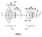
- Fig. 2 is a cross-sectional view illustrating lenses according to Example 2.
- the basic lens structure of a variable-power optical system according to Example 2 is similar to that according to Example 1 except that a meniscus-shaped positive lens L15 having a convex surface facing the object side is used in Example 2 instead of the plano-convex lens L15 according to Example 1.
- an object-side surface S12 and an image-side surface S13 of a lens L21 are aspheric surfaces.
- Lens data of the variable-power optical system according to Example 2 is shown in Table 4, aspheric data thereof is shown in Table 5, and various data thereof is shown in Table 6.
- Example 2 Lens data Si Ri Di Ndj vdj 1 18.8544 1.67 1.88300 40.8 2 9.6898 2.70 3 12.0747 1.07 1.88300 40.8 4 6.6167 3.26 5 14.7479 1.64 1.81600 46.6 6 9.5646 3.03 7 -31.7750 3.05 1.79952 42.2 8 11.3138 0.24 9 10.8296 1.55 1.92286 18.9 10 39.8198 Variable spacing D1 11(aperture stop) - Variable spacing D2 12* 13.4759 4.93 1.56384 60.7 13* -21.7202 0.85 14 14.0015 3.75 1.49700 81.6 15 -14.6216 0.10 16 99.6937 0.65 2.00330 28.3 17 7.8269 0.50 18 9.3574 3.08 1.57135 53 19 -21.9950 Variable spacing D3 20 ⁇ 1.50 1.51633 64.1 21 ⁇ [Table 5
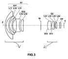
- Fig. 3 is a cross-sectional view illustrating lenses according to Example 3.
- the basic lens structure of a variable-power optical system according to Example 3 is the same as that according to Example 2.
- an object-side surface S12 and an image-side surface S13 of a lens L21 are aspheric surfaces.
- Lens data of the variable-power optical system according to Example 3 is shown in Table 7, aspheric data thereof is shown in Table 8, and various data thereof is shown in Table 9.
- Example 3 Lens data Si Ri Di Ndj vdj 1 21.8943 1.26 1.83481 42.7 2 11.7335 2.92 3 14.6451 1.10 1.88300 40.8 4 10.1764 2.84 5 16.4676 0.95 1.88300 40.8 6 10.7445 4.17 7 -35.7810 3.10 1.80400 46.6 8 16.1017 1.81 9 21.6836 3.10 1.92286 18.9 10 604.6536
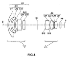
- Fig. 4 is a cross-sectional view illustrating lenses according to Example 4.
- the basic lens structure of a variable-power optical system according to Example 4 is the same as that according to Example 2.
- an object-side surface S12 and an image-side surface S13 of a lens L21 are aspheric surfaces.
- Lens data of the variable-power optical system according to Example 4 is shown in Table 10, aspheric data thereof is shown in Table 11, and various data thereof is shown in Table 12.
- Example 4 Lens data Si Ri Di Ndj ⁇ dj 1 22.6668 1.10 1.74320 49.3 2 10.5107 2.50 3 14.2655 1.10 1.72916 54.7 4 8.4469 3.01 5 20.6186 0.96 1.75500 52.3 6 9.0955 2.97 7 -39.4534 3.81 1.88300 40.8 8 18.7657 1.56 9 21.0326 2.94 1.92286 18.9 10 593.0192 Variable spacing D1 11(aperture stop) - Variable spacing D2 12* 13.1879 5.00 1.51633 64.1 13* -22.8785 0.81 14 12.8396 3.71 1.49700 81.6 15 -15.3298 0.10 16 38.9170 0.65 2.00330 28.3 17 7.6036 0.54 18 10.7694 3.18 1.48749 70.2 19 -16.9744 Variable spacing D3 20 ⁇ 1.50
- Fig. 5 is a cross-sectional view illustrating lenses according to Example 5.
- the basic lens structure of a variable-power optical system according to Example 5 is similar to that according to Example 1 except that a biconvex positive lens L15 is used in Example 5 instead of the plano-convex lens L15 according to Example 1.
- a biconvex positive lens L15 is used in Example 5 instead of the plano-convex lens L15 according to Example 1.
- an object-side surface S3 and an image-side surface S4 of a lens L12, and an object-side surface S12 and an image-side surface S13 of a lens L21 are aspheric surfaces.
- Lens data of the variable-power optical system according to Example 5 is shown in Table 13, aspheric data thereof is shown in Table 14, and various data thereof is shown in Table 15.
- Example 5 Lens data Si Ri Di Ndj vdj 1 20.1765 1.10 1.83481 42.7 2 10.4650 2.28 3* 14.7312 1.11 1.88300 40.8 4* 8.1241 2.85 5 19.4521 0.95 1.88300 40.8 6 9.6912 2.92 7 -39.6839 3.76 1.80400 46.6 8 17.9064 1.34 9 20.2777 2.93 1.92286 18.9 10 -1980.4893
- Fig. 6 is a cross-sectional view illustrating lenses according to Example 6.
- a variable-power optical system according to Example 6 includes a first lens group G1, an aperture stop St, a second lens group G2, and a third lens group G3.
- the basis lens structures of the first lens group G1 and the second lens group G2 of the variable-power optical system according to Example 6 are the same as those according to Example 2.
- the third lens group G3 of the variable-power optical system according to Example 6 is a fixed lens group that has a negative refractive power and does not move when power varies.
- the third lens group G3 includes two lenses, that is, a biconcave negative lens L31 and a biconvex positive lens L32.
- a variable spacing D3 is the gap between the second lens group G2 and the third lens group G3, unlike the above-mentioned Examples.
- an object-side surface S12 and an image-side surface S13 of a lens L21 are aspheric surfaces.
- Lens data of the variable-power optical system according to Example 6 is shown in Table 16, aspheric data thereof is shown in Table 17, and various data thereof is shown in Table 18.
- Example 6 Lens data Si Ri Di Ndj vdj 1 22.3555 1.10 1.77250 49.6 2 10.3707 2.32 3 13.5408 1.11 1.80610 40.9 4 9.2119 2.84 5 22.0033 0.95 1.83481 42.7 6 9.8981 2.95 7 -43.7206 3.74 1.80400 46.6 8 16.8156 1.29 9 17.5091 2.93 1.92286 18.9 10 119.6821 Variable spacing D1 11(aperture stop) - Variable spacing D2 12* 15.5208 4.91 1.62230 53.2 13* -23.0179 0.73 14 17.4185 3.65 1.49700 81.6 15 -12.9384 0.10 16 68.4022 0.66 2.00069 25.5 17 8.7393 0.50 18 13.1033 3.00 1.48749 70.2 19 -18.1878 Variable spacing D3 20 -39.7756 0.
- Table 19 shows values corresponding to Conditional expressions 1 to 4 in Examples 1 to 6. As can be seen from Table 19, Examples 1 to 6 all satisfy Conditional expressions 1 to 4. [Table 19] Example 1 Example 2 Example 3 Example 4 Example 5 Example 6 Conditional expression 1
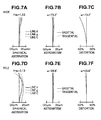
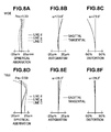
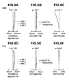
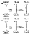
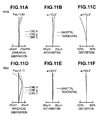
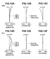
- Figs. 7A to 7C are aberration diagrams illustrating spherical aberration, astigmatism, and distortion of the variable-power optical system according to Example 1 at the wide angle end.
- Figs. 7D to 7F are aberration diagrams illustrating spherical aberration, astigmatism, and distortion of the variable-power optical system according to Example 1 at the telephoto end.
- Each of the aberration diagrams shows aberration using the d-line as a reference wavelength
- the spherical aberration diagram shows aberration with respect to the g-line (wavelength: 436 nm) and the C-line (wavelength: 656.3 nm).
- Fno means the F value.
- ⁇ means a half angle of view.
- Figs. 8A to 8F , Figs. 9A to 9F , Figs. 10A to 10F , Figs. 11A to 11F , and Figs. 12A to 12F are diagrams illustrating the aberrations of the variable-power optical systems according to Example 2, Example 3, Example 4, Example 5, and Example 6, respectively.
- the variable-power optical system having a variable power ratio of about 2.7 has a small structure, and the F value at the wide angle end is in the range of 1.33 to 1.78. That is, a fast lens system having a large aperture ratio is obtained.
- the variable-power optical system has the entire angle of view in the range of 144° to 148°, which is a wide range, at the wide angle end, accurately corrects each aberration, and has a high optical performance in the visible range both at the wide angle end and the telephoto end.
- Fig. 13 is a diagram schematically illustrating the structure of a monitoring camera according to another embodiment of the invention, which is provided with the variable-power optical system according to the embodiment of the invention.
- a monitoring camera 10 shown in Fig. 13 includes a lens device 6 and a camera body 7.
- a variable-power optical system 1 is provided in the lens device 6.
- Fig. 13 schematically illustrates the variable-power optical system 1 including the first lens group G1, the aperture stop St, and the second lens group G2.
- the imaging device 5 that captures the image of a subject formed by the variable-power optical system 1 is provided in the camera body 7.
- the imaging device 5 may include a CCD (charge coupled device) that converts an optical image formed by the variable-power optical system into electric signals and a CMOS (complementary metal oxide semiconductor).
- the imaging device 5 is arranged such that its imaging surface is aligned with the imaging surface of the variable-power optical system 1.
- An aperture diaphragm mechanism 8 that changes the diameter of the aperture stop St is provided above the lens device 6.
- a zoom knob 9 for changing the power of the variable-power optical system 1 and a focus knob 11 for adjusting the focus of the variable-power optical system 1 are provided below the lens device 6.
- variable-power optical system 1 Since the variable-power optical system 1 according to the embodiment of the invention has the above-mentioned advantages, the imaging apparatus according to this embodiment can have a small size and capture a high-quality image in a wide range even under low-brightness imaging conditions.
- the curvature radius, the surface spacing, the refractive index, and the Abbe number of each lens component are not limited to the values described in the above-mentioned numerical examples, but they may have other values.
- the monitoring camera is given as an example of the imaging apparatus, but the invention is not limited thereto.
- the invention can be applied to other imaging apparatuses, such as a television camera, a video camera, and an electronic still camera.
Landscapes
- Physics & Mathematics (AREA)
- General Physics & Mathematics (AREA)
- Optics & Photonics (AREA)
- Nonlinear Science (AREA)
- Lenses (AREA)
Applications Claiming Priority (1)
| Application Number | Priority Date | Filing Date | Title |
|---|---|---|---|
| JP2008170863A JP4672755B2 (ja) | 2008-06-30 | 2008-06-30 | 変倍光学系および撮像装置 |
Publications (2)
| Publication Number | Publication Date |
|---|---|
| EP2141529A1 EP2141529A1 (en) | 2010-01-06 |
| EP2141529B1 true EP2141529B1 (en) | 2011-11-23 |
Family
ID=40835300
Family Applications (1)
| Application Number | Title | Priority Date | Filing Date |
|---|---|---|---|
| EP09007484A Not-in-force EP2141529B1 (en) | 2008-06-30 | 2009-06-05 | Retrofocus type zoom lens comprising two lens groups |
Country Status (5)
| Country | Link |
|---|---|
| US (1) | US7933075B2 (enExample) |
| EP (1) | EP2141529B1 (enExample) |
| JP (1) | JP4672755B2 (enExample) |
| CN (1) | CN101620313B (enExample) |
| AT (1) | ATE534930T1 (enExample) |
Families Citing this family (13)
| Publication number | Priority date | Publication date | Assignee | Title |
|---|---|---|---|---|
| TW201120409A (en) * | 2009-12-10 | 2011-06-16 | Ind Tech Res Inst | Surveillance camera system and method |
| US8724232B2 (en) | 2010-10-29 | 2014-05-13 | Samsung Techwin Co., Ltd. | Zoom lens and photographing apparatus including the same |
| JP5718020B2 (ja) * | 2010-10-29 | 2015-05-13 | 三星テクウィン株式会社Samsung Techwin Co., Ltd | ズームレンズ及び撮像装置 |
| JP5724639B2 (ja) * | 2011-05-30 | 2015-05-27 | リコーイメージング株式会社 | ズームレンズ系及びこれを用いた光学機器 |
| JP6602027B2 (ja) * | 2015-03-13 | 2019-11-06 | キヤノン株式会社 | ズームレンズ及びそれを有する撮像装置 |
| KR102600453B1 (ko) * | 2016-02-19 | 2023-11-10 | 삼성전자주식회사 | 옵티칼 렌즈 어셈블리 및 이를 포함한 전자 장치 |
| CN108761735B (zh) * | 2018-07-13 | 2024-03-29 | 嘉兴中润光学科技股份有限公司 | 超大光圈广角镜头 |
| JP2020052349A (ja) * | 2018-09-28 | 2020-04-02 | 富士フイルム株式会社 | 撮像レンズ及び撮像装置 |
| CN111061051B (zh) * | 2020-01-15 | 2024-10-18 | 福建福光天瞳光学有限公司 | 一种短焦距高分辨率视觉镜头及其工作方法 |
| CN111650735B (zh) * | 2020-08-10 | 2020-12-01 | 嘉兴中润光学科技有限公司 | 一种大广角摄像装置和变焦镜头 |
| CN115437104B (zh) * | 2021-06-03 | 2025-09-16 | 信泰光学(深圳)有限公司 | 广角镜头 |
| CN115185072B (zh) * | 2022-06-01 | 2024-03-12 | 广东北创光电科技股份有限公司 | 一种非球面广角长法兰视频镜头 |
| CN119148355B (zh) * | 2024-10-11 | 2025-10-10 | 合肥综合性国家科学中心能源研究院(安徽省能源实验室) | 一种消热差宽谱段低畸变广角镜头 |
Family Cites Families (15)
| Publication number | Priority date | Publication date | Assignee | Title |
|---|---|---|---|---|
| JP2558138B2 (ja) * | 1988-02-08 | 1996-11-27 | オリンパス光学工業株式会社 | 変倍レンズ |
| JP3087303B2 (ja) | 1990-10-29 | 2000-09-11 | ミノルタ株式会社 | コンパクトなズームレンズ |
| JP2001343583A (ja) * | 2000-05-31 | 2001-12-14 | Matsushita Electric Ind Co Ltd | ズームレンズ及びそれを用いたビデオカメラ |
| GB2374744B (en) | 2001-04-18 | 2003-04-16 | Voxar Ltd | Correction of boundary artefacts in image data processing |
| JP3572037B2 (ja) * | 2001-08-24 | 2004-09-29 | キヤノン株式会社 | レンズ系及びそれを有する光学機器 |
| KR100615001B1 (ko) * | 2002-02-25 | 2006-08-25 | 마쯔시다덴기산교 가부시키가이샤 | 줌 렌즈 및 이를 이용한 비디오 카메라 및 디지털 스틸 카메라 |
| JP4280538B2 (ja) * | 2003-04-18 | 2009-06-17 | フジノン株式会社 | ズームレンズ |
| US6943958B2 (en) * | 2003-08-20 | 2005-09-13 | Olympus Corporation | Zoom lens system and camera using the same |
| JP4516291B2 (ja) * | 2003-08-20 | 2010-08-04 | オリンパス株式会社 | ズームレンズ及びそれを用いたカメラ。 |
| JP4642408B2 (ja) * | 2003-08-20 | 2011-03-02 | オリンパス株式会社 | ズームレンズ及びそれを用いたカメラ |
| JP4597623B2 (ja) * | 2003-10-08 | 2010-12-15 | 富士フイルム株式会社 | ズームレンズ |
| JP4596418B2 (ja) | 2004-09-27 | 2010-12-08 | 富士フイルム株式会社 | 変倍光学系 |
| JP2006119574A (ja) * | 2004-09-27 | 2006-05-11 | Fujinon Corp | 変倍光学系 |
| JP4945989B2 (ja) | 2005-09-29 | 2012-06-06 | 株式会社ニコン | ズームレンズ |
| JP4905779B2 (ja) * | 2006-09-07 | 2012-03-28 | 富士フイルム株式会社 | ズームレンズ |
-
2008
- 2008-06-30 JP JP2008170863A patent/JP4672755B2/ja not_active Expired - Fee Related
-
2009
- 2009-06-05 AT AT09007484T patent/ATE534930T1/de active
- 2009-06-05 EP EP09007484A patent/EP2141529B1/en not_active Not-in-force
- 2009-06-12 US US12/483,381 patent/US7933075B2/en not_active Expired - Fee Related
- 2009-06-15 CN CN2009101496183A patent/CN101620313B/zh not_active Expired - Fee Related
Also Published As
| Publication number | Publication date |
|---|---|
| CN101620313A (zh) | 2010-01-06 |
| US20090323199A1 (en) | 2009-12-31 |
| EP2141529A1 (en) | 2010-01-06 |
| CN101620313B (zh) | 2011-02-16 |
| ATE534930T1 (de) | 2011-12-15 |
| US7933075B2 (en) | 2011-04-26 |
| JP4672755B2 (ja) | 2011-04-20 |
| JP2010008917A (ja) | 2010-01-14 |
Similar Documents
| Publication | Publication Date | Title |
|---|---|---|
| EP2141529B1 (en) | Retrofocus type zoom lens comprising two lens groups | |
| JP5190997B2 (ja) | 変倍光学系および撮像装置 | |
| JP5280705B2 (ja) | 変倍光学系および撮像装置 | |
| JP2010008917A5 (enExample) | ||
| JP5767335B2 (ja) | ズームレンズおよび撮像装置 | |
| CN102033305A (zh) | 变倍光学系统及摄像装置 | |
| WO2013031180A1 (ja) | ズームレンズおよび撮像装置 | |
| WO2013031185A1 (ja) | ズームレンズおよび撮像装置 | |
| JP5767330B2 (ja) | ズームレンズおよび撮像装置 | |
| JP5778276B2 (ja) | ズームレンズおよび撮像装置 | |
| WO2013031184A1 (ja) | ズームレンズおよび撮像装置 | |
| WO2013031108A1 (ja) | ズームレンズおよび撮像装置 | |
| JP5767332B2 (ja) | ズームレンズおよび撮像装置 | |
| JP5767333B2 (ja) | ズームレンズおよび撮像装置 | |
| JP5767710B2 (ja) | ズームレンズおよび撮像装置 | |
| JP5767334B2 (ja) | ズームレンズおよび撮像装置 | |
| WO2013031178A1 (ja) | ズームレンズおよび撮像装置 | |
| US9097879B2 (en) | Zoom lens and imaging apparatus | |
| JP5766810B2 (ja) | ズームレンズおよび撮像装置 | |
| WO2013031179A1 (ja) | ズームレンズおよび撮像装置 | |
| WO2013031182A1 (ja) | ズームレンズおよび撮像装置 | |
| JP5767331B2 (ja) | ズームレンズおよび撮像装置 | |
| WO2013031189A1 (ja) | ズームレンズおよび撮像装置 |
Legal Events
| Date | Code | Title | Description |
|---|---|---|---|
| PUAI | Public reference made under article 153(3) epc to a published international application that has entered the european phase |
Free format text: ORIGINAL CODE: 0009012 |
|
| 17P | Request for examination filed |
Effective date: 20090605 |
|
| AK | Designated contracting states |
Kind code of ref document: A1 Designated state(s): AT BE BG CH CY CZ DE DK EE ES FI FR GB GR HR HU IE IS IT LI LT LU LV MC MK MT NL NO PL PT RO SE SI SK TR |
|
| 17Q | First examination report despatched |
Effective date: 20100818 |
|
| GRAP | Despatch of communication of intention to grant a patent |
Free format text: ORIGINAL CODE: EPIDOSNIGR1 |
|
| RAP1 | Party data changed (applicant data changed or rights of an application transferred) |
Owner name: FUJIFILM CORPORATION |
|
| GRAA | (expected) grant |
Free format text: ORIGINAL CODE: 0009210 |
|
| GRAS | Grant fee paid |
Free format text: ORIGINAL CODE: EPIDOSNIGR3 |
|
| AK | Designated contracting states |
Kind code of ref document: B1 Designated state(s): AT BE BG CH CY CZ DE DK EE ES FI FR GB GR HR HU IE IS IT LI LT LU LV MC MK MT NL NO PL PT RO SE SI SK TR |
|
| REG | Reference to a national code |
Ref country code: GB Ref legal event code: FG4D |
|
| RIN1 | Information on inventor provided before grant (corrected) |
Inventor name: TOMIOKA, UKYO |
|
| REG | Reference to a national code |
Ref country code: CH Ref legal event code: EP |
|
| REG | Reference to a national code |
Ref country code: IE Ref legal event code: FG4D |
|
| REG | Reference to a national code |
Ref country code: DE Ref legal event code: R096 Ref document number: 602009003790 Country of ref document: DE Effective date: 20120202 |
|
| REG | Reference to a national code |
Ref country code: NL Ref legal event code: VDEP Effective date: 20111123 |
|
| LTIE | Lt: invalidation of european patent or patent extension |
Effective date: 20111123 |
|
| PG25 | Lapsed in a contracting state [announced via postgrant information from national office to epo] |
Ref country code: IS Free format text: LAPSE BECAUSE OF FAILURE TO SUBMIT A TRANSLATION OF THE DESCRIPTION OR TO PAY THE FEE WITHIN THE PRESCRIBED TIME-LIMIT Effective date: 20120323 Ref country code: NO Free format text: LAPSE BECAUSE OF FAILURE TO SUBMIT A TRANSLATION OF THE DESCRIPTION OR TO PAY THE FEE WITHIN THE PRESCRIBED TIME-LIMIT Effective date: 20120223 Ref country code: LT Free format text: LAPSE BECAUSE OF FAILURE TO SUBMIT A TRANSLATION OF THE DESCRIPTION OR TO PAY THE FEE WITHIN THE PRESCRIBED TIME-LIMIT Effective date: 20111123 |
|
| PG25 | Lapsed in a contracting state [announced via postgrant information from national office to epo] |
Ref country code: GR Free format text: LAPSE BECAUSE OF FAILURE TO SUBMIT A TRANSLATION OF THE DESCRIPTION OR TO PAY THE FEE WITHIN THE PRESCRIBED TIME-LIMIT Effective date: 20120224 Ref country code: SE Free format text: LAPSE BECAUSE OF FAILURE TO SUBMIT A TRANSLATION OF THE DESCRIPTION OR TO PAY THE FEE WITHIN THE PRESCRIBED TIME-LIMIT Effective date: 20111123 Ref country code: HR Free format text: LAPSE BECAUSE OF FAILURE TO SUBMIT A TRANSLATION OF THE DESCRIPTION OR TO PAY THE FEE WITHIN THE PRESCRIBED TIME-LIMIT Effective date: 20111123 Ref country code: BE Free format text: LAPSE BECAUSE OF FAILURE TO SUBMIT A TRANSLATION OF THE DESCRIPTION OR TO PAY THE FEE WITHIN THE PRESCRIBED TIME-LIMIT Effective date: 20111123 Ref country code: SI Free format text: LAPSE BECAUSE OF FAILURE TO SUBMIT A TRANSLATION OF THE DESCRIPTION OR TO PAY THE FEE WITHIN THE PRESCRIBED TIME-LIMIT Effective date: 20111123 Ref country code: NL Free format text: LAPSE BECAUSE OF FAILURE TO SUBMIT A TRANSLATION OF THE DESCRIPTION OR TO PAY THE FEE WITHIN THE PRESCRIBED TIME-LIMIT Effective date: 20111123 Ref country code: PT Free format text: LAPSE BECAUSE OF FAILURE TO SUBMIT A TRANSLATION OF THE DESCRIPTION OR TO PAY THE FEE WITHIN THE PRESCRIBED TIME-LIMIT Effective date: 20120323 Ref country code: LV Free format text: LAPSE BECAUSE OF FAILURE TO SUBMIT A TRANSLATION OF THE DESCRIPTION OR TO PAY THE FEE WITHIN THE PRESCRIBED TIME-LIMIT Effective date: 20111123 |
|
| PG25 | Lapsed in a contracting state [announced via postgrant information from national office to epo] |
Ref country code: CY Free format text: LAPSE BECAUSE OF FAILURE TO SUBMIT A TRANSLATION OF THE DESCRIPTION OR TO PAY THE FEE WITHIN THE PRESCRIBED TIME-LIMIT Effective date: 20111123 |
|
| PG25 | Lapsed in a contracting state [announced via postgrant information from national office to epo] |
Ref country code: BG Free format text: LAPSE BECAUSE OF FAILURE TO SUBMIT A TRANSLATION OF THE DESCRIPTION OR TO PAY THE FEE WITHIN THE PRESCRIBED TIME-LIMIT Effective date: 20120223 Ref country code: EE Free format text: LAPSE BECAUSE OF FAILURE TO SUBMIT A TRANSLATION OF THE DESCRIPTION OR TO PAY THE FEE WITHIN THE PRESCRIBED TIME-LIMIT Effective date: 20111123 Ref country code: DK Free format text: LAPSE BECAUSE OF FAILURE TO SUBMIT A TRANSLATION OF THE DESCRIPTION OR TO PAY THE FEE WITHIN THE PRESCRIBED TIME-LIMIT Effective date: 20111123 Ref country code: SK Free format text: LAPSE BECAUSE OF FAILURE TO SUBMIT A TRANSLATION OF THE DESCRIPTION OR TO PAY THE FEE WITHIN THE PRESCRIBED TIME-LIMIT Effective date: 20111123 Ref country code: CZ Free format text: LAPSE BECAUSE OF FAILURE TO SUBMIT A TRANSLATION OF THE DESCRIPTION OR TO PAY THE FEE WITHIN THE PRESCRIBED TIME-LIMIT Effective date: 20111123 |
|
| PG25 | Lapsed in a contracting state [announced via postgrant information from national office to epo] |
Ref country code: RO Free format text: LAPSE BECAUSE OF FAILURE TO SUBMIT A TRANSLATION OF THE DESCRIPTION OR TO PAY THE FEE WITHIN THE PRESCRIBED TIME-LIMIT Effective date: 20111123 Ref country code: PL Free format text: LAPSE BECAUSE OF FAILURE TO SUBMIT A TRANSLATION OF THE DESCRIPTION OR TO PAY THE FEE WITHIN THE PRESCRIBED TIME-LIMIT Effective date: 20111123 Ref country code: IT Free format text: LAPSE BECAUSE OF FAILURE TO SUBMIT A TRANSLATION OF THE DESCRIPTION OR TO PAY THE FEE WITHIN THE PRESCRIBED TIME-LIMIT Effective date: 20111123 |
|
| REG | Reference to a national code |
Ref country code: AT Ref legal event code: MK05 Ref document number: 534930 Country of ref document: AT Kind code of ref document: T Effective date: 20111123 |
|
| PLBE | No opposition filed within time limit |
Free format text: ORIGINAL CODE: 0009261 |
|
| STAA | Information on the status of an ep patent application or granted ep patent |
Free format text: STATUS: NO OPPOSITION FILED WITHIN TIME LIMIT |
|
| 26N | No opposition filed |
Effective date: 20120824 |
|
| REG | Reference to a national code |
Ref country code: DE Ref legal event code: R097 Ref document number: 602009003790 Country of ref document: DE Effective date: 20120824 |
|
| PG25 | Lapsed in a contracting state [announced via postgrant information from national office to epo] |
Ref country code: MC Free format text: LAPSE BECAUSE OF NON-PAYMENT OF DUE FEES Effective date: 20120630 Ref country code: AT Free format text: LAPSE BECAUSE OF FAILURE TO SUBMIT A TRANSLATION OF THE DESCRIPTION OR TO PAY THE FEE WITHIN THE PRESCRIBED TIME-LIMIT Effective date: 20111123 |
|
| PG25 | Lapsed in a contracting state [announced via postgrant information from national office to epo] |
Ref country code: MK Free format text: LAPSE BECAUSE OF FAILURE TO SUBMIT A TRANSLATION OF THE DESCRIPTION OR TO PAY THE FEE WITHIN THE PRESCRIBED TIME-LIMIT Effective date: 20111123 |
|
| REG | Reference to a national code |
Ref country code: IE Ref legal event code: MM4A |
|
| REG | Reference to a national code |
Ref country code: FR Ref legal event code: ST Effective date: 20130228 |
|
| PG25 | Lapsed in a contracting state [announced via postgrant information from national office to epo] |
Ref country code: ES Free format text: LAPSE BECAUSE OF FAILURE TO SUBMIT A TRANSLATION OF THE DESCRIPTION OR TO PAY THE FEE WITHIN THE PRESCRIBED TIME-LIMIT Effective date: 20120305 Ref country code: IE Free format text: LAPSE BECAUSE OF NON-PAYMENT OF DUE FEES Effective date: 20120605 Ref country code: FR Free format text: LAPSE BECAUSE OF NON-PAYMENT OF DUE FEES Effective date: 20120702 |
|
| PG25 | Lapsed in a contracting state [announced via postgrant information from national office to epo] |
Ref country code: FI Free format text: LAPSE BECAUSE OF FAILURE TO SUBMIT A TRANSLATION OF THE DESCRIPTION OR TO PAY THE FEE WITHIN THE PRESCRIBED TIME-LIMIT Effective date: 20111123 |
|
| PG25 | Lapsed in a contracting state [announced via postgrant information from national office to epo] |
Ref country code: MT Free format text: LAPSE BECAUSE OF FAILURE TO SUBMIT A TRANSLATION OF THE DESCRIPTION OR TO PAY THE FEE WITHIN THE PRESCRIBED TIME-LIMIT Effective date: 20111123 |
|
| PGFP | Annual fee paid to national office [announced via postgrant information from national office to epo] |
Ref country code: GB Payment date: 20130605 Year of fee payment: 5 |
|
| REG | Reference to a national code |
Ref country code: CH Ref legal event code: PL |
|
| PG25 | Lapsed in a contracting state [announced via postgrant information from national office to epo] |
Ref country code: TR Free format text: LAPSE BECAUSE OF FAILURE TO SUBMIT A TRANSLATION OF THE DESCRIPTION OR TO PAY THE FEE WITHIN THE PRESCRIBED TIME-LIMIT Effective date: 20111123 Ref country code: LI Free format text: LAPSE BECAUSE OF NON-PAYMENT OF DUE FEES Effective date: 20130630 Ref country code: CH Free format text: LAPSE BECAUSE OF NON-PAYMENT OF DUE FEES Effective date: 20130630 |
|
| PG25 | Lapsed in a contracting state [announced via postgrant information from national office to epo] |
Ref country code: LU Free format text: LAPSE BECAUSE OF NON-PAYMENT OF DUE FEES Effective date: 20120605 |
|
| PG25 | Lapsed in a contracting state [announced via postgrant information from national office to epo] |
Ref country code: HU Free format text: LAPSE BECAUSE OF FAILURE TO SUBMIT A TRANSLATION OF THE DESCRIPTION OR TO PAY THE FEE WITHIN THE PRESCRIBED TIME-LIMIT Effective date: 20090605 |
|
| GBPC | Gb: european patent ceased through non-payment of renewal fee |
Effective date: 20140605 |
|
| PG25 | Lapsed in a contracting state [announced via postgrant information from national office to epo] |
Ref country code: GB Free format text: LAPSE BECAUSE OF NON-PAYMENT OF DUE FEES Effective date: 20140605 |
|
| PGFP | Annual fee paid to national office [announced via postgrant information from national office to epo] |
Ref country code: DE Payment date: 20170530 Year of fee payment: 9 |
|
| REG | Reference to a national code |
Ref country code: DE Ref legal event code: R082 Ref document number: 602009003790 Country of ref document: DE Representative=s name: KLUNKER IP PATENTANWAELTE PARTG MBB, DE |
|
| REG | Reference to a national code |
Ref country code: DE Ref legal event code: R119 Ref document number: 602009003790 Country of ref document: DE |
|
| PG25 | Lapsed in a contracting state [announced via postgrant information from national office to epo] |
Ref country code: DE Free format text: LAPSE BECAUSE OF NON-PAYMENT OF DUE FEES Effective date: 20190101 |