EP2140990A1 - Outil à tête de frappe interchangeable. - Google Patents
Outil à tête de frappe interchangeable. Download PDFInfo
- Publication number
- EP2140990A1 EP2140990A1 EP09354030A EP09354030A EP2140990A1 EP 2140990 A1 EP2140990 A1 EP 2140990A1 EP 09354030 A EP09354030 A EP 09354030A EP 09354030 A EP09354030 A EP 09354030A EP 2140990 A1 EP2140990 A1 EP 2140990A1
- Authority
- EP
- European Patent Office
- Prior art keywords
- striking head
- tool
- metal
- head
- buffer piece
- Prior art date
- Legal status (The legal status is an assumption and is not a legal conclusion. Google has not performed a legal analysis and makes no representation as to the accuracy of the status listed.)
- Granted
Links
Images



Classifications
-
- B—PERFORMING OPERATIONS; TRANSPORTING
- B27—WORKING OR PRESERVING WOOD OR SIMILAR MATERIAL; NAILING OR STAPLING MACHINES IN GENERAL
- B27L—REMOVING BARK OR VESTIGES OF BRANCHES; SPLITTING WOOD; MANUFACTURE OF VENEER, WOODEN STICKS, WOOD SHAVINGS, WOOD FIBRES OR WOOD POWDER
- B27L7/00—Arrangements for splitting wood
- B27L7/06—Arrangements for splitting wood using wedges, knives or spreaders
-
- A—HUMAN NECESSITIES
- A01—AGRICULTURE; FORESTRY; ANIMAL HUSBANDRY; HUNTING; TRAPPING; FISHING
- A01G—HORTICULTURE; CULTIVATION OF VEGETABLES, FLOWERS, RICE, FRUIT, VINES, HOPS OR SEAWEED; FORESTRY; WATERING
- A01G23/00—Forestry
- A01G23/02—Transplanting, uprooting, felling or delimbing trees
- A01G23/099—Auxiliary devices, e.g. felling wedges
-
- B—PERFORMING OPERATIONS; TRANSPORTING
- B25—HAND TOOLS; PORTABLE POWER-DRIVEN TOOLS; MANIPULATORS
- B25D—PERCUSSIVE TOOLS
- B25D1/00—Hand hammers; Hammer heads of special shape or materials
- B25D1/02—Inserts or attachments forming the striking part of hammer heads
-
- B—PERFORMING OPERATIONS; TRANSPORTING
- B25—HAND TOOLS; PORTABLE POWER-DRIVEN TOOLS; MANIPULATORS
- B25D—PERCUSSIVE TOOLS
- B25D1/00—Hand hammers; Hammer heads of special shape or materials
- B25D1/14—Hand hammers; Hammer heads of special shape or materials having plural striking faces
-
- B—PERFORMING OPERATIONS; TRANSPORTING
- B26—HAND CUTTING TOOLS; CUTTING; SEVERING
- B26B—HAND-HELD CUTTING TOOLS NOT OTHERWISE PROVIDED FOR
- B26B23/00—Axes; Hatchets
Definitions
- a wood slot tool comprising a steel metal body having a cutting edge, and a striking head at the opposite end, said head being made of a material of lower hardness than steel.
- the upper surface of the corner is generally pierced with a hole in which the anti-flash material is inserted. To limit the premature wear of this material, it has already been proposed to position an O-ring one centimeter below the striking surface to reduce the burst effect following repeated impact impacts.
- the object of the invention is to provide a tool equipped with an improved impact head, with anti-flash security, easily interchangeable, and having an optimum life.
- the tool according to the invention is characterized in that the striking head is formed by an interchangeable plastic buffer part, attached to a frustoconical tip protruding from the metal body, said buffer part being surrounded externally by an annular metal ring serving as fret and wear indicator.
- the metal ring is housed under a shoulder of the striking head, and has an axial length less than that of the striking head, the difference in length corresponding to the maximum wear interval of said head.
- the axial length of the metal ring is greater than the height of the frustoconical tip of the body, and the body is equipped with a stop located at the interface with the tip to serve as a support member for the buffer piece, as well as to the metal ring when said buffer piece is in the state of maximum wear.
- the tool may consist of a wedge for the wood slot, a merlin, a mass, or any other striking tool.
- the tool is constituted by a wedge 10 for splitting wood, which comprises a metal body 11, in particular of steel, and of substantially prismatic shape terminating at the lower end by a straight cutting edge 12.
- a strike head 13 formed by an interchangeable buffer part 17, which is attached to a frustoconical tip 14 projecting from the body 11 in the axial direction.
- the buffer part 17 serves to damp the mechanical shock coming from a mass or a merlin, and is made of a plastic anti-shine material having a hardness and a density lower than those of the steel of the body 11.
- the plastic buffer part 17 of the strike head 13 is surrounded externally by an annular metal ring serving both as a hoop and a wear indicator.
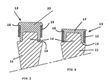
- the ring 15 is fitted under a shoulder 16 of the buffer piece 17, and covers at least 60% of the axial length of the strike head 13 before use ( figure 3 ).
- the height of the fixed tip 14 of the metal body 11 remains always less than the axial length of the buffer piece 17 before and after wear of the latter ( Figures 3 and 4 ).
- the end of the plastic buffer piece 17 is permanently supported on an annular abutment 18 of the body 11, said abutment 18 being arranged at the interface with the end-piece 14.
- the width of this abutment 18 is slightly greater than the diameter outside the ring 15. In the state of maximum wear of the buffer piece 17, the metal ring 15 also bears on the stop 18 ( figure 4 ).
- the buffer piece 17 is arranged between the ring 15 and the tip 14, both being made of metallic material.
- the ring 15 covers both the buffer piece 17 over more than 60% of its axial length, and also the tip 14.
- the plastic material is thus wedged in the radial direction between the ring 15 and the tip 14, contributing to strengthen the resistance of the material in the state of compression.
- the tool is constituted by a mass 30 having a handle 31 and a metal body 110 equipped with a frustoconical tip 14 and an interchangeable striker head 13, which have identical structures to those of the corner 10 of the Figures 1 to 4 .
- the tool may also be a merlin having a handle 41 and a metal body 210 equipped with a frustoconical tip 14 for receiving the interchangeable striking head 13.
Landscapes
- Life Sciences & Earth Sciences (AREA)
- Engineering & Computer Science (AREA)
- Mechanical Engineering (AREA)
- Forests & Forestry (AREA)
- Biodiversity & Conservation Biology (AREA)
- Ecology (AREA)
- Environmental Sciences (AREA)
- Wood Science & Technology (AREA)
- Percussive Tools And Related Accessories (AREA)
- Insertion Pins And Rivets (AREA)
Abstract
Description
- L'invention concerne un outil pour la fente de bois comprenant un corps métallique en acier ayant une arête de coupe, et une tête de frappe à l'extrémité opposée, ladite tête étant réalisée en un matériau de dureté inférieure à l'acier.
- Pour la fente de bois, il est connu d'utiliser des coins métalliques en acier équipés de têtes de frappe ne générant pas d'éclats lors du choc créé par un merlin ou une masse. La matière anti-éclat de ces têtes de frappe connues est moins dure que l'acier, et peut être du bois, de l'aluminium ou du plastique.
- La surface supérieure du coin est généralement percée d'un trou dans lequel est insérée la matière anti-éclat. Pour limiter l'usure prématurée de cette matière, on a déjà proposé de positionner un anneau torique à un centimètre sous la surface de frappe pour diminuer l'effet d'éclatement suite aux chocs d'impact répétés.
- La durée de vie de ces coins connus reste néanmoins limitée, et il est nécessaire de remplacer régulièrement la matière tampon des têtes de frappe.
- L'objet de l'invention consiste à réaliser un outil équipé d'une tête de frappe perfectionnée, à sécurité anti-éclat, facilement interchangeable, et ayant une durée de vie optimum.
- L'outil selon l'invention est caractérisé en ce que la tête de frappe est formée par une pièce tampon en plastique interchangeable, rapportée sur un embout tronconique faisant saillie du corps métallique, ladite pièce tampon étant entourée extérieurement par une bague métallique annulaire servant de frette et d'indicateur d'usure.
- Selon un mode de réalisation préférentiel, la bague métallique est logée sous un épaulement de la tête de frappe, et présente une longueur axiale inférieure à celle de la tête de frappe, la différence de longueur correspondant à l'intervalle d'usure maximum de ladite tête. La longueur axiale de la bague métallique est supérieure à la hauteur de l'embout tronconique du corps, et le corps est équipé d'une butée située au niveau de l'interface avec l'embout pour servir d'organe d'appui à la pièce tampon, ainsi qu'à la bague métallique lorsque ladite pièce tampon se trouve dans l'état d'usure maximum.
- L'outil peut être constitué par un coin pour la fente du bois, un merlin, une masse, ou tout autre outil de frappe.
- D'autres avantages et caractéristiques ressortiront plus clairement de la description qui va suivre de plusieurs modes de réalisation de l'invention donnés à titre d'exemples non limitatifs et représentés aux dessins annexés, dans lesquels :
- la
figure 1 est une vue en élévation du coin selon l'invention avec la tête de frappe illustrée en position assemblée sur l'embout du corps métallique; - la
figure 2 montre une vue de profil du coin de lafigure 1 en position démontée de la tête de frappe; - les
figures 3 et 4 représentent des vues en coupe de la tête de frappe de lafigure 1 , respectivement dans l'état neuf avant utilisation, et dans l'état d'usure maximum nécessitant le remplacement ; - la
figure 5 est une vue en élévation d'une masse équipée d'une tête de frappe selon l'invention ; - la
figure 6 est une vue de profil de lafigure 5 après démontage de la tête de frappe ; - les
figures 7 et 8 sont des vues identiques desfigures 5 et 6 d'une autre variante relative à un merlin. - En référence aux
figures 1 à 4 , l'outil est constitué par un coin 10 pour fendre du bois, lequel comporte un corps 11 métallique, notamment en acier, et de forme sensiblement prismatique se terminant à l'extrémité inférieure par une arête de coupe 12 rectiligne. - A l'extrémité supérieure se trouve une tête de frappe 13 formée par une pièce tampon 17 interchangeable, laquelle est rapportée sur un embout 14 tronconique faisant saillie du corps 11 dans la direction axiale. La pièce tampon 17 sert à amortir le choc mécanique en provenance d'une masse ou d'un merlin, et est réalisée en un matériau plastique anti-éclat, ayant une dureté et une masse volumique inférieures à celles de l'acier du corps 11.
- La pièce tampon 17 en plastique de la tête de frappe 13 est entourée extérieurement par une bague 15 métallique annulaire servant à la fois de frette et d'indicateur d'usure. La bague 15 est emmanchée sous un épaulement 16 de la pièce tampon 17, et recouvre au moins 60% de la longueur axiale de la tête de frappe 13 avant utilisation (
figure 3 ). - La hauteur de l'embout 14 fixe du corps 11 métallique reste toujours inférieure à la longueur axiale de la pièce tampon 17 avant et après usure de cette dernière (
figures 3 et 4 ). - Le bout de la pièce tampon 17 en plastique prend appui en permanence sur une butée 18 annulaire du corps 11, ladite butée 18 étant agencée au niveau de l'interface avec l'embout 14. La largeur de cette butée 18 est légèrement supérieure au diamètre extérieur de la bague 15. Dans l'état d'usure maximum de la pièce tampon 17, la bague 15 métallique prend également appui sur la butée 18 (
figure 4 ). - On note sur la
figure 3 que la pièce tampon 17 est agencée entre la bague 15 et l'embout 14, tous deux étant en matériau métallique. La bague 15 recouvre à la fois la pièce tampon 17 sur plus de 60% de sa longueur axiale, et également l'embout 14. La matière plastique est ainsi coincée dans la direction radiale entre la bague 15 et l'embout 14, contribuant à renforcer la résistance de la matière dans l'état de compression. Plus on tape sur la tête de frappe 13, plus la matière plastique de la pièce tampon 17 est comprimée entre la bague 15 et l'embout 14. - Sur les
figures 5 et 6 , l'outil est constitué par une masse 30 ayant un manche 31 et un corps 110 métallique équipé d'un embout 14 tronconique et d'une tête de frappe 13 interchangeable, qui ont des structures identiques à celles du coin 10 desfigures 1 à 4 . - Selon les
figures 7 et 8 , l'outil peut aussi être un merlin ayant un manche 41 et un corps 210 métallique équipé d'un embout 14 tronconique pour la réception de la tête de frappe 13 interchangeable.
Claims (7)
- Outil comprenant un corps (11, 110, 210) métallique en acier, et une tête de frappe (13) réalisée en un matériau de dureté inférieure à l'acier, caractérisé en ce que la tête de frappe (13) est formée par une pièce tampon (17) en plastique interchangeable, rapportée sur un embout (14) tronconique faisant saillie du corps (11, 110, 210) métallique, ladite pièce tampon étant entourée extérieurement par une bague (15) métallique annulaire servant de frette et d'indicateur d'usure.
- Outil selon la revendication 1, caractérisé en ce que la bague (15) métallique est logée sous un épaulement (16) de la tête de frappe (13), et présente une longueur axiale inférieure à celle de la tête de frappe, la différence de longueur correspondant à l'intervalle d'usure maximum de ladite tête.
- Outil selon la revendication 2, caractérisé en ce que la bague (15) métallique recouvre au moins 60% de la longueur axiale de la tête de frappe (13) avant utilisation.
- Outil selon la revendication 2 ou 3, caractérisé en ce que la longueur axiale de la bague (15) métallique est supérieure à la hauteur de l'embout (14) tronconique du corps (11).
- Outil selon l'une des revendications précédentes, caractérisé en ce que le corps (11, 110, 210) est équipé d'une butée (18) située au niveau de l'interface avec l'embout (14) pour servir d'organe d'appui à la pièce tampon (17), ainsi qu'à la bague (15) métallique lorsque ladite pièce tampon se trouve dans l'état d'usure maximum.
- Outil selon l'une des revendications précédentes, caractérisé en ce que le corps est constitué par un coin (10) pour fendre du bois, la tête de frappe (13) étant agencée à l'opposé de l'arête de coupe (12).
- Outil selon l'une des revendications 1 à 5, caractérisé en ce que le corps est constitué par un merlin (40), ou une masse (30).
Applications Claiming Priority (1)
| Application Number | Priority Date | Filing Date | Title |
|---|---|---|---|
| FR0803800A FR2933325B1 (fr) | 2008-07-04 | 2008-07-04 | Coin a tete de frappe interchangeable |
Publications (2)
| Publication Number | Publication Date |
|---|---|
| EP2140990A1 true EP2140990A1 (fr) | 2010-01-06 |
| EP2140990B1 EP2140990B1 (fr) | 2012-08-08 |
Family
ID=40029009
Family Applications (1)
| Application Number | Title | Priority Date | Filing Date |
|---|---|---|---|
| EP20090354030 Active EP2140990B1 (fr) | 2008-07-04 | 2009-06-30 | Outil à tête de frappe interchangeable. |
Country Status (2)
| Country | Link |
|---|---|
| EP (1) | EP2140990B1 (fr) |
| FR (1) | FR2933325B1 (fr) |
Cited By (1)
| Publication number | Priority date | Publication date | Assignee | Title |
|---|---|---|---|---|
| WO2015002606A1 (fr) * | 2013-07-04 | 2015-01-08 | Ijk Innovation Ab | Kit de fendeuse à bois |
Families Citing this family (1)
| Publication number | Priority date | Publication date | Assignee | Title |
|---|---|---|---|---|
| FR3129313B1 (fr) * | 2021-11-24 | 2024-02-02 | Mob Mondelin Sas | Marteau comprenant une fonction de maillet |
Citations (14)
| Publication number | Priority date | Publication date | Assignee | Title |
|---|---|---|---|---|
| DE270749C (fr) | ||||
| US356299A (en) * | 1887-01-18 | Mallet | ||
| US460115A (en) * | 1891-09-29 | Mallet | ||
| US1195423A (en) * | 1916-08-22 | Wedge | ||
| US1356413A (en) * | 1919-12-10 | 1920-10-19 | Staub Otto | Wood-splitting means |
| DE633270C (de) * | 1936-07-23 | Xaver Antholzner | Spaltkeil mit Querverzahnung | |
| DE802602C (de) * | 1948-10-02 | 1951-02-15 | Gottfried Reissinger | Keil mit Holzeinsatz, insbesondere fuer die Holzhauerei |
| US3130762A (en) * | 1961-06-21 | 1964-04-28 | Henry K Kerr | Hammer with detachable striking head faces |
| US3377052A (en) * | 1966-11-14 | 1968-04-09 | Jack D. Hagen | Hand impact wedge means |
| EP0182174A1 (fr) * | 1984-11-21 | 1986-05-28 | François Bolle | Coin d'abattage pour bûcheron |
| US5690316A (en) * | 1996-08-06 | 1997-11-25 | Madjarac; John | Timber wedge |
| US20040165375A1 (en) * | 2003-02-25 | 2004-08-26 | Hansjorg Kirchner | Plexor |
| DE202004016785U1 (de) * | 2004-10-29 | 2005-02-24 | Lysek, Mirko, Dipl.-Ing. | Holzspaltwerkzeug für maschinell angetriebene Schlagwerkzeuge, insbesondere Hämmer |
| FR2905625A3 (fr) | 2006-09-11 | 2008-03-14 | Himmelberger Zeughammerwerk Le | Accesoire pour des outils de percussion |
-
2008
- 2008-07-04 FR FR0803800A patent/FR2933325B1/fr active Active
-
2009
- 2009-06-30 EP EP20090354030 patent/EP2140990B1/fr active Active
Patent Citations (14)
| Publication number | Priority date | Publication date | Assignee | Title |
|---|---|---|---|---|
| DE270749C (fr) | ||||
| US356299A (en) * | 1887-01-18 | Mallet | ||
| US460115A (en) * | 1891-09-29 | Mallet | ||
| US1195423A (en) * | 1916-08-22 | Wedge | ||
| DE633270C (de) * | 1936-07-23 | Xaver Antholzner | Spaltkeil mit Querverzahnung | |
| US1356413A (en) * | 1919-12-10 | 1920-10-19 | Staub Otto | Wood-splitting means |
| DE802602C (de) * | 1948-10-02 | 1951-02-15 | Gottfried Reissinger | Keil mit Holzeinsatz, insbesondere fuer die Holzhauerei |
| US3130762A (en) * | 1961-06-21 | 1964-04-28 | Henry K Kerr | Hammer with detachable striking head faces |
| US3377052A (en) * | 1966-11-14 | 1968-04-09 | Jack D. Hagen | Hand impact wedge means |
| EP0182174A1 (fr) * | 1984-11-21 | 1986-05-28 | François Bolle | Coin d'abattage pour bûcheron |
| US5690316A (en) * | 1996-08-06 | 1997-11-25 | Madjarac; John | Timber wedge |
| US20040165375A1 (en) * | 2003-02-25 | 2004-08-26 | Hansjorg Kirchner | Plexor |
| DE202004016785U1 (de) * | 2004-10-29 | 2005-02-24 | Lysek, Mirko, Dipl.-Ing. | Holzspaltwerkzeug für maschinell angetriebene Schlagwerkzeuge, insbesondere Hämmer |
| FR2905625A3 (fr) | 2006-09-11 | 2008-03-14 | Himmelberger Zeughammerwerk Le | Accesoire pour des outils de percussion |
Cited By (1)
| Publication number | Priority date | Publication date | Assignee | Title |
|---|---|---|---|---|
| WO2015002606A1 (fr) * | 2013-07-04 | 2015-01-08 | Ijk Innovation Ab | Kit de fendeuse à bois |
Also Published As
| Publication number | Publication date |
|---|---|
| FR2933325B1 (fr) | 2010-08-27 |
| FR2933325A1 (fr) | 2010-01-08 |
| EP2140990B1 (fr) | 2012-08-08 |
Similar Documents
| Publication | Publication Date | Title |
|---|---|---|
| EP2011927B1 (fr) | Clavette de verrouillage et dispositif de verrouillage avec une telle clavette. | |
| EP2468454B1 (fr) | Outil de frappe à main permettant de réduire les vibrations, et son procédé de fabrication | |
| FR2862544A1 (fr) | Piolet pour l'alpinisme avec poignee de prehension reglable | |
| CA2887777C (fr) | Dispositif d'etancheite pour appareil hydraulique a percussions, et appareil hydraulique a percussions comprenant un tel dispositif d'etancheite | |
| EP2032317A2 (fr) | Support pour une série d'outils | |
| WO1999019598A1 (fr) | Accouplement pour dispositif a transmission de forces | |
| EP3287239B1 (fr) | Outil a frapper equipe d'un embout de guidage | |
| EP2140990B1 (fr) | Outil à tête de frappe interchangeable. | |
| FR2981290A3 (fr) | Dispositif de serrage | |
| FR3058664B1 (fr) | Appareil a percussions | |
| EP1975749B1 (fr) | Pièce d'horlogerie dont le mouvement est tenu élastiquement | |
| FR2960812A1 (fr) | Frein d'outil pare-poussiere, piece d'introduction d'outil, raccord d'outil, appareil portatif. | |
| WO2005058553A1 (fr) | Dispositif de retenue d’une clavette d’outil pour appareil de demolition a percussion | |
| FR2935288A3 (fr) | Coin a refendre. | |
| EP2845692B1 (fr) | Manche pour outil de frappe à main, outil de frappe à main et procédé de fabrication d'un outil de frappe main | |
| FR2996793A1 (fr) | Dispositif de machine-outil portative | |
| FR2870474A1 (fr) | Marteau multifonctions | |
| EP1760332B1 (fr) | Article à fixer sur un support au moyen d'un outil à gaz comprime | |
| FR3129313A1 (fr) | Marteau comprenant une fonction de maillet | |
| EP3208047B1 (fr) | Outil de frappe absorbant et procede de fabrication d'un tel outil | |
| FR3004979A1 (fr) | Marteau a percussion comportant un moyen deguidage d'orientation de l'outil de coupe | |
| FR2905625A3 (fr) | Accesoire pour des outils de percussion | |
| BE564797A (fr) | ||
| BE469273A (fr) | ||
| FR2972131A1 (fr) | Dispositif d'assemblage |
Legal Events
| Date | Code | Title | Description |
|---|---|---|---|
| PUAI | Public reference made under article 153(3) epc to a published international application that has entered the european phase |
Free format text: ORIGINAL CODE: 0009012 |
|
| AK | Designated contracting states |
Kind code of ref document: A1 Designated state(s): AT BE BG CH CY CZ DE DK EE ES FI FR GB GR HR HU IE IS IT LI LT LU LV MC MK MT NL NO PL PT RO SE SI SK TR |
|
| 17P | Request for examination filed |
Effective date: 20100902 |
|
| 17Q | First examination report despatched |
Effective date: 20110905 |
|
| GRAP | Despatch of communication of intention to grant a patent |
Free format text: ORIGINAL CODE: EPIDOSNIGR1 |
|
| GRAS | Grant fee paid |
Free format text: ORIGINAL CODE: EPIDOSNIGR3 |
|
| GRAA | (expected) grant |
Free format text: ORIGINAL CODE: 0009210 |
|
| AK | Designated contracting states |
Kind code of ref document: B1 Designated state(s): AT BE BG CH CY CZ DE DK EE ES FI FR GB GR HR HU IE IS IT LI LT LU LV MC MK MT NL NO PL PT RO SE SI SK TR |
|
| REG | Reference to a national code |
Ref country code: GB Ref legal event code: FG4D Free format text: NOT ENGLISH |
|
| REG | Reference to a national code |
Ref country code: AT Ref legal event code: REF Ref document number: 569496 Country of ref document: AT Kind code of ref document: T Effective date: 20120815 Ref country code: CH Ref legal event code: EP |
|
| REG | Reference to a national code |
Ref country code: IE Ref legal event code: FG4D Free format text: LANGUAGE OF EP DOCUMENT: FRENCH |
|
| REG | Reference to a national code |
Ref country code: DE Ref legal event code: R096 Ref document number: 602009008806 Country of ref document: DE Effective date: 20121004 |
|
| REG | Reference to a national code |
Ref country code: SE Ref legal event code: TRGR |
|
| REG | Reference to a national code |
Ref country code: NL Ref legal event code: VDEP Effective date: 20120808 |
|
| REG | Reference to a national code |
Ref country code: AT Ref legal event code: MK05 Ref document number: 569496 Country of ref document: AT Kind code of ref document: T Effective date: 20120808 |
|
| RAP2 | Party data changed (patent owner data changed or rights of a patent transferred) |
Owner name: FISKARS FRANCE SAS |
|
| REG | Reference to a national code |
Ref country code: LT Ref legal event code: MG4D Effective date: 20120808 |
|
| PG25 | Lapsed in a contracting state [announced via postgrant information from national office to epo] |
Ref country code: NO Free format text: LAPSE BECAUSE OF FAILURE TO SUBMIT A TRANSLATION OF THE DESCRIPTION OR TO PAY THE FEE WITHIN THE PRESCRIBED TIME-LIMIT Effective date: 20121108 Ref country code: CY Free format text: LAPSE BECAUSE OF FAILURE TO SUBMIT A TRANSLATION OF THE DESCRIPTION OR TO PAY THE FEE WITHIN THE PRESCRIBED TIME-LIMIT Effective date: 20120808 Ref country code: LT Free format text: LAPSE BECAUSE OF FAILURE TO SUBMIT A TRANSLATION OF THE DESCRIPTION OR TO PAY THE FEE WITHIN THE PRESCRIBED TIME-LIMIT Effective date: 20120808 Ref country code: HR Free format text: LAPSE BECAUSE OF FAILURE TO SUBMIT A TRANSLATION OF THE DESCRIPTION OR TO PAY THE FEE WITHIN THE PRESCRIBED TIME-LIMIT Effective date: 20120808 Ref country code: IS Free format text: LAPSE BECAUSE OF FAILURE TO SUBMIT A TRANSLATION OF THE DESCRIPTION OR TO PAY THE FEE WITHIN THE PRESCRIBED TIME-LIMIT Effective date: 20121208 Ref country code: AT Free format text: LAPSE BECAUSE OF FAILURE TO SUBMIT A TRANSLATION OF THE DESCRIPTION OR TO PAY THE FEE WITHIN THE PRESCRIBED TIME-LIMIT Effective date: 20120808 |
|
| PG25 | Lapsed in a contracting state [announced via postgrant information from national office to epo] |
Ref country code: GR Free format text: LAPSE BECAUSE OF FAILURE TO SUBMIT A TRANSLATION OF THE DESCRIPTION OR TO PAY THE FEE WITHIN THE PRESCRIBED TIME-LIMIT Effective date: 20121109 Ref country code: PT Free format text: LAPSE BECAUSE OF FAILURE TO SUBMIT A TRANSLATION OF THE DESCRIPTION OR TO PAY THE FEE WITHIN THE PRESCRIBED TIME-LIMIT Effective date: 20121210 Ref country code: PL Free format text: LAPSE BECAUSE OF FAILURE TO SUBMIT A TRANSLATION OF THE DESCRIPTION OR TO PAY THE FEE WITHIN THE PRESCRIBED TIME-LIMIT Effective date: 20120808 Ref country code: SI Free format text: LAPSE BECAUSE OF FAILURE TO SUBMIT A TRANSLATION OF THE DESCRIPTION OR TO PAY THE FEE WITHIN THE PRESCRIBED TIME-LIMIT Effective date: 20120808 Ref country code: LV Free format text: LAPSE BECAUSE OF FAILURE TO SUBMIT A TRANSLATION OF THE DESCRIPTION OR TO PAY THE FEE WITHIN THE PRESCRIBED TIME-LIMIT Effective date: 20120808 |
|
| PG25 | Lapsed in a contracting state [announced via postgrant information from national office to epo] |
Ref country code: NL Free format text: LAPSE BECAUSE OF FAILURE TO SUBMIT A TRANSLATION OF THE DESCRIPTION OR TO PAY THE FEE WITHIN THE PRESCRIBED TIME-LIMIT Effective date: 20120808 |
|
| REG | Reference to a national code |
Ref country code: DE Ref legal event code: R082 Ref document number: 602009008806 Country of ref document: DE Representative=s name: CABINET HECKE, FR |
|
| PG25 | Lapsed in a contracting state [announced via postgrant information from national office to epo] |
Ref country code: RO Free format text: LAPSE BECAUSE OF FAILURE TO SUBMIT A TRANSLATION OF THE DESCRIPTION OR TO PAY THE FEE WITHIN THE PRESCRIBED TIME-LIMIT Effective date: 20120808 Ref country code: DK Free format text: LAPSE BECAUSE OF FAILURE TO SUBMIT A TRANSLATION OF THE DESCRIPTION OR TO PAY THE FEE WITHIN THE PRESCRIBED TIME-LIMIT Effective date: 20120808 Ref country code: ES Free format text: LAPSE BECAUSE OF FAILURE TO SUBMIT A TRANSLATION OF THE DESCRIPTION OR TO PAY THE FEE WITHIN THE PRESCRIBED TIME-LIMIT Effective date: 20121119 Ref country code: EE Free format text: LAPSE BECAUSE OF FAILURE TO SUBMIT A TRANSLATION OF THE DESCRIPTION OR TO PAY THE FEE WITHIN THE PRESCRIBED TIME-LIMIT Effective date: 20120808 Ref country code: CZ Free format text: LAPSE BECAUSE OF FAILURE TO SUBMIT A TRANSLATION OF THE DESCRIPTION OR TO PAY THE FEE WITHIN THE PRESCRIBED TIME-LIMIT Effective date: 20120808 |
|
| REG | Reference to a national code |
Ref country code: CH Ref legal event code: NV Representative=s name: CABINET ROLAND NITHARDT CONSEILS EN PROPRIETE , CH Ref country code: CH Ref legal event code: PFA Owner name: FISKARS FRANCE SAS, FR Free format text: FORMER OWNER: FISKARS BRANDS FRANCE, FR |
|
| PG25 | Lapsed in a contracting state [announced via postgrant information from national office to epo] |
Ref country code: IT Free format text: LAPSE BECAUSE OF FAILURE TO SUBMIT A TRANSLATION OF THE DESCRIPTION OR TO PAY THE FEE WITHIN THE PRESCRIBED TIME-LIMIT Effective date: 20120808 Ref country code: SK Free format text: LAPSE BECAUSE OF FAILURE TO SUBMIT A TRANSLATION OF THE DESCRIPTION OR TO PAY THE FEE WITHIN THE PRESCRIBED TIME-LIMIT Effective date: 20120808 |
|
| PLBE | No opposition filed within time limit |
Free format text: ORIGINAL CODE: 0009261 |
|
| STAA | Information on the status of an ep patent application or granted ep patent |
Free format text: STATUS: NO OPPOSITION FILED WITHIN TIME LIMIT |
|
| REG | Reference to a national code |
Ref country code: DE Ref legal event code: R081 Ref document number: 602009008806 Country of ref document: DE Owner name: FISKARS FRANCE SAS, FR Free format text: FORMER OWNER: FISKARS BRANDS FRANCE, VILLEBON SUR YVETTE, FR Effective date: 20130426 Ref country code: DE Ref legal event code: R082 Ref document number: 602009008806 Country of ref document: DE Representative=s name: CABINET HECKE, FR Effective date: 20130426 |
|
| 26N | No opposition filed |
Effective date: 20130510 |
|
| PG25 | Lapsed in a contracting state [announced via postgrant information from national office to epo] |
Ref country code: BG Free format text: LAPSE BECAUSE OF FAILURE TO SUBMIT A TRANSLATION OF THE DESCRIPTION OR TO PAY THE FEE WITHIN THE PRESCRIBED TIME-LIMIT Effective date: 20121108 |
|
| REG | Reference to a national code |
Ref country code: DE Ref legal event code: R097 Ref document number: 602009008806 Country of ref document: DE Effective date: 20130510 |
|
| PG25 | Lapsed in a contracting state [announced via postgrant information from national office to epo] |
Ref country code: MC Free format text: LAPSE BECAUSE OF FAILURE TO SUBMIT A TRANSLATION OF THE DESCRIPTION OR TO PAY THE FEE WITHIN THE PRESCRIBED TIME-LIMIT Effective date: 20120808 |
|
| REG | Reference to a national code |
Ref country code: IE Ref legal event code: MM4A |
|
| PG25 | Lapsed in a contracting state [announced via postgrant information from national office to epo] |
Ref country code: IE Free format text: LAPSE BECAUSE OF NON-PAYMENT OF DUE FEES Effective date: 20130630 |
|
| PG25 | Lapsed in a contracting state [announced via postgrant information from national office to epo] |
Ref country code: MT Free format text: LAPSE BECAUSE OF FAILURE TO SUBMIT A TRANSLATION OF THE DESCRIPTION OR TO PAY THE FEE WITHIN THE PRESCRIBED TIME-LIMIT Effective date: 20120808 |
|
| PG25 | Lapsed in a contracting state [announced via postgrant information from national office to epo] |
Ref country code: TR Free format text: LAPSE BECAUSE OF FAILURE TO SUBMIT A TRANSLATION OF THE DESCRIPTION OR TO PAY THE FEE WITHIN THE PRESCRIBED TIME-LIMIT Effective date: 20120808 |
|
| PG25 | Lapsed in a contracting state [announced via postgrant information from national office to epo] |
Ref country code: LU Free format text: LAPSE BECAUSE OF NON-PAYMENT OF DUE FEES Effective date: 20130630 Ref country code: MK Free format text: LAPSE BECAUSE OF FAILURE TO SUBMIT A TRANSLATION OF THE DESCRIPTION OR TO PAY THE FEE WITHIN THE PRESCRIBED TIME-LIMIT Effective date: 20120808 Ref country code: HU Free format text: LAPSE BECAUSE OF FAILURE TO SUBMIT A TRANSLATION OF THE DESCRIPTION OR TO PAY THE FEE WITHIN THE PRESCRIBED TIME-LIMIT; INVALID AB INITIO Effective date: 20090630 |
|
| REG | Reference to a national code |
Ref country code: FR Ref legal event code: PLFP Year of fee payment: 8 |
|
| REG | Reference to a national code |
Ref country code: FR Ref legal event code: PLFP Year of fee payment: 9 |
|
| REG | Reference to a national code |
Ref country code: FR Ref legal event code: PLFP Year of fee payment: 10 |
|
| REG | Reference to a national code |
Ref country code: CH Ref legal event code: NV Representative=s name: ACTOSPHERE SARL, CH |
|
| P01 | Opt-out of the competence of the unified patent court (upc) registered |
Effective date: 20230825 |
|
| PGFP | Annual fee paid to national office [announced via postgrant information from national office to epo] |
Ref country code: FI Payment date: 20250616 Year of fee payment: 17 |
|
| PGFP | Annual fee paid to national office [announced via postgrant information from national office to epo] |
Ref country code: DE Payment date: 20250618 Year of fee payment: 17 |
|
| PGFP | Annual fee paid to national office [announced via postgrant information from national office to epo] |
Ref country code: GB Payment date: 20250618 Year of fee payment: 17 |
|
| PGFP | Annual fee paid to national office [announced via postgrant information from national office to epo] |
Ref country code: BE Payment date: 20250618 Year of fee payment: 17 |
|
| PGFP | Annual fee paid to national office [announced via postgrant information from national office to epo] |
Ref country code: FR Payment date: 20250617 Year of fee payment: 17 |
|
| PGFP | Annual fee paid to national office [announced via postgrant information from national office to epo] |
Ref country code: SE Payment date: 20250618 Year of fee payment: 17 |
|
| PGFP | Annual fee paid to national office [announced via postgrant information from national office to epo] |
Ref country code: CH Payment date: 20250701 Year of fee payment: 17 |