EP2139654B1 - Machine-outil entraînée par un moteur - Google Patents
Machine-outil entraînée par un moteur Download PDFInfo
- Publication number
- EP2139654B1 EP2139654B1 EP08716952.0A EP08716952A EP2139654B1 EP 2139654 B1 EP2139654 B1 EP 2139654B1 EP 08716952 A EP08716952 A EP 08716952A EP 2139654 B1 EP2139654 B1 EP 2139654B1
- Authority
- EP
- European Patent Office
- Prior art keywords
- eccentric
- output shaft
- tool
- machine tool
- coupling member
- Prior art date
- Legal status (The legal status is an assumption and is not a legal conclusion. Google has not performed a legal analysis and makes no representation as to the accuracy of the status listed.)
- Not-in-force
Links
Images

Classifications
-
- B—PERFORMING OPERATIONS; TRANSPORTING
- B27—WORKING OR PRESERVING WOOD OR SIMILAR MATERIAL; NAILING OR STAPLING MACHINES IN GENERAL
- B27B—SAWS FOR WOOD OR SIMILAR MATERIAL; COMPONENTS OR ACCESSORIES THEREFOR
- B27B19/00—Other reciprocating saws with power drive; Fret-saws
- B27B19/006—Other reciprocating saws with power drive; Fret-saws with oscillating saw blades; Hand saws with oscillating saw blades
-
- B—PERFORMING OPERATIONS; TRANSPORTING
- B24—GRINDING; POLISHING
- B24B—MACHINES, DEVICES, OR PROCESSES FOR GRINDING OR POLISHING; DRESSING OR CONDITIONING OF ABRADING SURFACES; FEEDING OF GRINDING, POLISHING, OR LAPPING AGENTS
- B24B23/00—Portable grinding machines, e.g. hand-guided; Accessories therefor
- B24B23/04—Portable grinding machines, e.g. hand-guided; Accessories therefor with oscillating grinding tools; Accessories therefor
Definitions
- the invention relates to a motor-driven machine tool with a drive shaft driven by a drive unit and an output shaft on which the tool is received, according to the preamble of claim 1.
- a machine tool is the DE 42 03 090 C1 refer to.
- a hand tool machine is described with an oscillating drivable working shaft, on which a tool is received, wherein the oscillating drive leads to a rotary pendulum motion of the tool, which can be used both for grinding and for cutting.
- the work or tool shaft with the tool is driven by a non-rotatably connected arm, which cooperates as part of a Exzenterkoppel founded with an eccentric, which is driven by an electric motor.
- the DE 42 03 890 C1 shows a hand-held cutter with an electric drive motor, the rotor shaft carries an eccentric cam, which cooperates with a pivot lever with a fork, wherein the pivot lever is disposed on an output shaft, at the free end of a tool is attached.
- the rotational movement of the rotor shaft 11 is transmitted via the eccentric cam and the pivot lever in an oscillating rotational movement of the output shaft.
- the rotor shaft and the output shaft are parallel to each other.
- the pivot lever is located in the region of the tool facing away from the end face on the output shaft.
- the output shaft thus represents the parallel offset, axial extension of the rotor shaft. Overall, this results in a relatively large space requirement in the axial direction.
- the invention has for its object to provide a compact, motor-driven machine tool with pendulum to be driven tool.
- the motor-driven machine tool which is in particular a hand tool whose tool performs a rotary pendulum movement, has parallel to each other arranged input and output shafts, which is additionally provided that the output shaft extends at least partially in height and parallel to the drive unit.
- Another advantage of the parallel arrangement is that the motion transmission between the input and output shaft due to the parallel axes of rotation without play or at least with reduced clearance is feasible.
- a linear or planar contact of the components participating in the eccentric coupling device between the input and output shafts is possible with one another; a point-like power transmission, which occurs for example in the prior art at an angle arranged waves and locally high force loads with the risk of increased play can be avoided.
- the eccentric coupling device comprises a coupling member and an eccentric member, which are each arranged on different shafts, wherein the coupling member preferably on the Output shaft and the eccentric advantageous sitting on the drive shaft.
- the rotational movement of the revolving eccentric member is transmitted via the coupling member in the rotary pendulum movement of the output shaft. Due to the parallel arrangement of the drive and output shaft, a linear or flat contact between the coupling member and the eccentric member can be realized.
- the eccentric member is expediently designed as eccentric cam, whose contour is scanned by the coupling member.
- the coupling member is designed, for example fork-shaped, wherein the two forks engage around the eccentric member.
- the planar or linear contact between coupling member and eccentric member is effected in particular by part-circular or possibly also circular formation of the contiguous contours of both components.
- the linear or planar system allows a better distribution of the forces to be transmitted and thus a lower punctual load.
- the coupling member of the coupling device is arranged adjacent to the tool on the output shaft.
- the drive unit is designed as an electric motor and the stator of the electric motor is arranged on the side facing away from the tool in the housing of the machine tool.
- the positioning of the coupling device on the side facing the tool allows a correspondingly short design of the output shaft, which is still supported by the fact that the drive shaft is also located on the side facing the tool and is rotationally urged by the drive unit.
- the installation space length is primarily determined by the drive unit, that is, as a rule, by the electric motor.
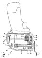
- hand tool 1 comprises in a housing 9 an electric drive motor 2, consisting of a housing-fixed stator 3 and an armature or rotor 4, on the rotatably and coaxially a drive shaft 5 is arranged.
- the rotational movement of the drive shaft 5 is transmitted via an eccentric coupling 8 to an output shaft 6, which carries a tool 7.
- the eccentric coupling 8 By means of the eccentric coupling 8, the rotary movement of the drive shaft 5 is transmitted in a rotary pendulum movement of the output shaft 6.
- the Exzenterkoppel consists of a coupling fork 12 which is rotatably connected to the output shaft 6, and an eccentric cam 13 which is rotatably connected to the drive shaft 5, wherein the coupling fork 12 abuts the contour of the eccentric cam 13, so that relative to the axis of rotation 10 of the drive shaft 5 eccentric movement of the eccentric cam 13 can be scanned by the coupling fork 12 and converted into an oscillating pendulum motion about the axis of rotation 11 of the output shaft 6.
- the eccentric coupling device 8 is adjacent to pivot bearings 14 and 15, respectively, via which the drive shaft 5 and the output shaft 6 are rotatably mounted in the housing 9 on their front side facing the tool 7.
- the components of the eccentric coupling device 8, that is to say the coupling fork 12 and the eccentric cam 13, are thus adjacent to the end face of the respective shafts facing the tool 7.
- the coupling fork 12 as part of the Exzenterkoppel drove 8 two forks 12a and 12b, which include the contour of the eccentric cam 13.
- the section between the fork tines 12a and 12b is expediently part-circular in shape and adapted to the circular shape of the eccentric cam 13, so that an areal contact between the coupling fork 12 and the outer contour of the eccentric cam 13 is given over an angular section.
Landscapes
- Engineering & Computer Science (AREA)
- Mechanical Engineering (AREA)
- Life Sciences & Earth Sciences (AREA)
- Wood Science & Technology (AREA)
- Forests & Forestry (AREA)
- Connection Of Motors, Electrical Generators, Mechanical Devices, And The Like (AREA)
- Finish Polishing, Edge Sharpening, And Grinding By Specific Grinding Devices (AREA)
- Sawing (AREA)
Claims (4)
- Machine-outil entraînée par un moteur, en particulier machine-outil portative (1) dotée d'un outil (7) devant être entraîné de manière rotative, comprenant un arbre d'entraînement (5) entraîné par une unité d'entraînement (2) et un arbre de sortie (6) sur lequel l'outil (7) est reçu, le mouvement rotatif de l'arbre d'entraînement (5) pouvant être transformé en un mouvement oscillant de l'arbre de sortie (6) par le biais d'un dispositif d'accouplement excentrique (8), le dispositif d'accouplement excentrique (8) comportant un organe d'accouplement (12) et un organe excentrique (13) qui repose sur l'un des arbres (5, 6) et l'organe d'accouplement (12) étant en liaison fonctionnelle avec l'organe excentrique (13), les arbres d'entraînement et de sortie (5, 6) étant disposés parallèlement l'un à l'autre et l'arbre de sortie (6) s'étendant au moins partiellement à hauteur de l'unité d'entraînement (2) et parallèlement à celle-ci, l'unité d'entraînement (2) étant réalisée sous forme de moteur électrique et le stator (3) du moteur électrique (2) étant disposé dans le boîtier (9) de la machine-outil (1) du côté opposé à l'outil (7),
caractérisée en ce que l'organe d'accouplement (12) du dispositif d'accouplement excentrique (8) est disposé à proximité de l'outil (7) sur l'arbre de sortie (6) et en ce que l'arbre de sortie (6), vu dans la direction axiale, chevauche le stator (3) sur approximativement la moitié de sa longueur. - Machine-outil selon la revendication 1, caractérisée en ce que l'organe excentrique est réalisé sous la forme d'une came excentrique (13) reliée solidement à l'arbre d'entraînement (5) et en ce que l'organe d'accouplement (12) s'applique contre le contour de la came excentrique (13).
- Machine-outil selon la revendication 1 ou 2, caractérisée en ce que l'organe d'accouplement (12) est réalisé en forme de fourche, les dents de la fourche (12a, 12b) venant en prise autour de l'organe excentrique (13).
- Machine-outil selon la revendication 2 ou 3, caractérisée en ce que la came excentrique (13) ainsi que la portion de l'organe d'accouplement (12) s'appliquant contre la came excentrique présentent respectivement un contour au moins partiellement circulaire et sont au moins approximativement en appui de manière linéaire ou à plat l'une contre l'autre.
Applications Claiming Priority (2)
| Application Number | Priority Date | Filing Date | Title |
|---|---|---|---|
| DE102007018465A DE102007018465A1 (de) | 2007-04-19 | 2007-04-19 | Motorisch angetriebene Werkzeugmaschine |
| PCT/EP2008/052011 WO2008128802A1 (fr) | 2007-04-19 | 2008-02-19 | Machine-outil entraînée par un moteur |
Publications (2)
| Publication Number | Publication Date |
|---|---|
| EP2139654A1 EP2139654A1 (fr) | 2010-01-06 |
| EP2139654B1 true EP2139654B1 (fr) | 2014-04-09 |
Family
ID=39428087
Family Applications (1)
| Application Number | Title | Priority Date | Filing Date |
|---|---|---|---|
| EP08716952.0A Not-in-force EP2139654B1 (fr) | 2007-04-19 | 2008-02-19 | Machine-outil entraînée par un moteur |
Country Status (5)
| Country | Link |
|---|---|
| US (1) | US8096856B2 (fr) |
| EP (1) | EP2139654B1 (fr) |
| CN (1) | CN101663140B (fr) |
| DE (1) | DE102007018465A1 (fr) |
| WO (1) | WO2008128802A1 (fr) |
Families Citing this family (19)
| Publication number | Priority date | Publication date | Assignee | Title |
|---|---|---|---|---|
| US20110081847A1 (en) * | 2009-10-05 | 2011-04-07 | Tai-Her Yang | Motor parallel transmission portable angle grinder |
| US8925931B2 (en) | 2010-04-29 | 2015-01-06 | Black & Decker Inc. | Oscillating tool |
| US9186770B2 (en) | 2010-04-29 | 2015-11-17 | Black & Decker Inc. | Oscillating tool attachment feature |
| US9073195B2 (en) | 2010-04-29 | 2015-07-07 | Black & Decker Inc. | Universal accessory for oscillating power tool |
| US9149923B2 (en) | 2010-11-09 | 2015-10-06 | Black & Decker Inc. | Oscillating tools and accessories |
| DE102011010745A1 (de) * | 2011-02-09 | 2012-08-09 | Robert Bosch Gmbh | Werkzeugmaschine mit einer hin- und hergehenden Abtriebsspindel |
| DE102011015117A1 (de) * | 2011-03-22 | 2012-09-27 | C. & E. Fein Gmbh | Handwerkzeug |
| USD832666S1 (en) | 2012-07-16 | 2018-11-06 | Black & Decker Inc. | Oscillating saw blade |
| CN104249340B (zh) * | 2013-06-27 | 2017-05-31 | 苏州宝时得电动工具有限公司 | 摆动动力工具 |
| CN104249341A (zh) * | 2013-06-27 | 2014-12-31 | 苏州宝时得电动工具有限公司 | 摆动动力工具 |
| DE102014202218A1 (de) * | 2014-02-06 | 2015-08-06 | Robert Bosch Gmbh | Handwerkzeugmaschine mit einem elektronisch kommutierten Elektromotor |
| JP6403589B2 (ja) * | 2015-02-02 | 2018-10-10 | 株式会社マキタ | 作業工具 |
| CN105835012B (zh) | 2015-02-02 | 2020-08-21 | 株式会社牧田 | 作业工具 |
| JP6697894B2 (ja) * | 2016-02-19 | 2020-05-27 | 株式会社マキタ | 作業工具 |
| EP3357645B1 (fr) | 2016-02-19 | 2019-11-27 | Makita Corporation | Outil de travail |
| DE102016223508A1 (de) * | 2016-11-28 | 2018-05-30 | Robert Bosch Gmbh | Tragbare Werkzeugmaschine |
| USD814900S1 (en) | 2017-01-16 | 2018-04-10 | Black & Decker Inc. | Blade for oscillating power tools |
| US10265778B2 (en) | 2017-01-16 | 2019-04-23 | Black & Decker Inc. | Accessories for oscillating power tools |
| EP3385034B1 (fr) | 2017-03-29 | 2019-10-16 | Makita Corporation | Outil de travail |
Family Cites Families (17)
| Publication number | Priority date | Publication date | Assignee | Title |
|---|---|---|---|---|
| US1464351A (en) * | 1923-08-07 | casey | ||
| US2350098A (en) * | 1941-12-31 | 1944-05-30 | Black & Decker Mfg Co | Oscillating sander |
| US2671476A (en) | 1950-02-02 | 1954-03-09 | Syntron Co | Portable belt-driven power handsaw |
| DE7436615U (de) * | 1974-11-02 | 1976-05-06 | Robert Bosch Gmbh, 7000 Stuttgart | Insbesondere hochtouriger schwingschleifer |
| JPS5854961B2 (ja) * | 1975-08-03 | 1983-12-07 | 日立工機株式会社 | シンドウセツダンコウグ |
| GB1566025A (en) | 1976-02-14 | 1980-04-30 | Ishihara M | Method and machine for forming a groove in a body of material |
| US4787430A (en) | 1987-02-23 | 1988-11-29 | Ryobi Ltd. | Duplicating router |
| DE4203890C1 (en) * | 1992-02-11 | 1992-10-08 | Fritz Gross Kg Elektrowerkzeuge Und Holzbearbeitungsmaschinen, O-8355 Neustadt, De | Hand-held cutter for sheet metal etc. - has electric micro-motor with eccentric CAM connected to cutting blade shaft |
| CH685154A5 (de) * | 1992-04-21 | 1995-04-13 | Richard E Arnegger | Vorrichtung zur Erzeugung von Trennschnitten. |
| US5482499A (en) * | 1993-11-18 | 1996-01-09 | Ryobi Limited | Sanding apparatus |
| EP0829237A3 (fr) * | 1996-09-12 | 1998-08-12 | Ricana Ag | Appareil de coupe avec outil de coupe sur un essieu moteur oscillant |
| US5856715A (en) * | 1996-12-13 | 1999-01-05 | Ryobi North America, Inc. | Portable electrical power tool having a rare earth permanent magnet motor |
| US6926595B2 (en) * | 2002-04-30 | 2005-08-09 | C.&E. Fein Gmbh & Co. Kg | Oscillatory drive |
| DE102004047812B4 (de) * | 2004-09-29 | 2022-09-15 | Robert Bosch Gmbh | Schleifhandwerkzeugmaschine, insbesondere Akkuschleifhandwerkzeugmaschine |
| DE102004047811A1 (de) * | 2004-09-29 | 2006-03-30 | Robert Bosch Gmbh | Schleifhandwerkzeugmaschine, insbesondere Akkuschleifhandwerkzeugmaschine |
| DE202004021498U1 (de) | 2004-10-19 | 2008-06-26 | Robert Bosch Gmbh | Vorrichtung zum Befestigen eines Werkzeugs an einer oszillierend antreibbaren Antriebswelle einer Handwerkzeugmaschine |
| JP4525532B2 (ja) * | 2005-08-29 | 2010-08-18 | 日立工機株式会社 | ジグソー |
-
2007
- 2007-04-19 DE DE102007018465A patent/DE102007018465A1/de not_active Withdrawn
-
2008
- 2008-02-19 WO PCT/EP2008/052011 patent/WO2008128802A1/fr not_active Ceased
- 2008-02-19 CN CN2008800125885A patent/CN101663140B/zh not_active Expired - Fee Related
- 2008-02-19 EP EP08716952.0A patent/EP2139654B1/fr not_active Not-in-force
- 2008-02-19 US US12/374,693 patent/US8096856B2/en not_active Expired - Fee Related
Also Published As
| Publication number | Publication date |
|---|---|
| US20100003906A1 (en) | 2010-01-07 |
| WO2008128802A1 (fr) | 2008-10-30 |
| US8096856B2 (en) | 2012-01-17 |
| EP2139654A1 (fr) | 2010-01-06 |
| CN101663140A (zh) | 2010-03-03 |
| CN101663140B (zh) | 2012-11-28 |
| DE102007018465A1 (de) | 2008-10-23 |
Similar Documents
| Publication | Publication Date | Title |
|---|---|---|
| EP2139654B1 (fr) | Machine-outil entraînée par un moteur | |
| EP2139647B1 (fr) | Machine-outil entraînée par un moteur | |
| EP2673102B1 (fr) | Machine-outil munie d'une broche menée à mouvement de va-et-vient | |
| EP2198691B1 (fr) | Appareil de travail | |
| DE102007018466A1 (de) | Motorisch angetriebene Werkzeugmaschine | |
| DE202008001759U1 (de) | Oszillierend antreibbare Werkzeugmaschine | |
| EP2686148A1 (fr) | Dispositif de serrage d'outils | |
| DE112009005440B4 (de) | Stichsäge | |
| EP3038780B1 (fr) | Dispositif de contrepoids | |
| DE102009035232B4 (de) | Schneidsatz für Haarschneidemaschinen | |
| EP2024150B1 (fr) | Machine-outil à main avec outil entraîné en oscillation et en mouvement pendulaire | |
| WO2012013389A1 (fr) | Outil amovible | |
| EP2490849B1 (fr) | Machine-outil | |
| EP2608931A1 (fr) | Machine-outil | |
| EP2681023B1 (fr) | Dispositif de séparation pour machine-outil | |
| EP2460758A1 (fr) | Entraînement rotatif hydraulique | |
| WO2012116841A1 (fr) | Système de machine-outil | |
| EP2890524B1 (fr) | Systeme machine-outil | |
| WO2010124777A1 (fr) | Transmission pour appareils avec outil à double sens de rotation | |
| EP3946791B1 (fr) | Scie sabre | |
| EP2527111A1 (fr) | Fraiseuse avec commande oscillante | |
| EP2904893B1 (fr) | Machine-outil, notamment taille-haie | |
| DE971561C (de) | Landwirtschaftliches Anbaugeraet fuer Traktoren | |
| DE4203890C1 (en) | Hand-held cutter for sheet metal etc. - has electric micro-motor with eccentric CAM connected to cutting blade shaft | |
| EP1166611A1 (fr) | Dispositif d'entrainement |
Legal Events
| Date | Code | Title | Description |
|---|---|---|---|
| PUAI | Public reference made under article 153(3) epc to a published international application that has entered the european phase |
Free format text: ORIGINAL CODE: 0009012 |
|
| 17P | Request for examination filed |
Effective date: 20091119 |
|
| AK | Designated contracting states |
Kind code of ref document: A1 Designated state(s): AT BE BG CH CY CZ DE DK EE ES FI FR GB GR HR HU IE IS IT LI LT LU LV MC MT NL NO PL PT RO SE SI SK TR |
|
| 17Q | First examination report despatched |
Effective date: 20100223 |
|
| DAX | Request for extension of the european patent (deleted) | ||
| GRAP | Despatch of communication of intention to grant a patent |
Free format text: ORIGINAL CODE: EPIDOSNIGR1 |
|
| INTG | Intention to grant announced |
Effective date: 20131122 |
|
| GRAS | Grant fee paid |
Free format text: ORIGINAL CODE: EPIDOSNIGR3 |
|
| GRAA | (expected) grant |
Free format text: ORIGINAL CODE: 0009210 |
|
| AK | Designated contracting states |
Kind code of ref document: B1 Designated state(s): AT BE BG CH CY CZ DE DK EE ES FI FR GB GR HR HU IE IS IT LI LT LU LV MC MT NL NO PL PT RO SE SI SK TR |
|
| REG | Reference to a national code |
Ref country code: GB Ref legal event code: FG4D Free format text: NOT ENGLISH |
|
| REG | Reference to a national code |
Ref country code: AT Ref legal event code: REF Ref document number: 661085 Country of ref document: AT Kind code of ref document: T Effective date: 20140415 Ref country code: CH Ref legal event code: EP |
|
| REG | Reference to a national code |
Ref country code: IE Ref legal event code: FG4D Free format text: LANGUAGE OF EP DOCUMENT: GERMAN |
|
| REG | Reference to a national code |
Ref country code: DE Ref legal event code: R096 Ref document number: 502008011569 Country of ref document: DE Effective date: 20140522 |
|
| REG | Reference to a national code |
Ref country code: NL Ref legal event code: VDEP Effective date: 20140409 |
|
| REG | Reference to a national code |
Ref country code: LT Ref legal event code: MG4D |
|
| PG25 | Lapsed in a contracting state [announced via postgrant information from national office to epo] |
Ref country code: FI Free format text: LAPSE BECAUSE OF FAILURE TO SUBMIT A TRANSLATION OF THE DESCRIPTION OR TO PAY THE FEE WITHIN THE PRESCRIBED TIME-LIMIT Effective date: 20140409 Ref country code: NO Free format text: LAPSE BECAUSE OF FAILURE TO SUBMIT A TRANSLATION OF THE DESCRIPTION OR TO PAY THE FEE WITHIN THE PRESCRIBED TIME-LIMIT Effective date: 20140709 Ref country code: IS Free format text: LAPSE BECAUSE OF FAILURE TO SUBMIT A TRANSLATION OF THE DESCRIPTION OR TO PAY THE FEE WITHIN THE PRESCRIBED TIME-LIMIT Effective date: 20140809 Ref country code: BG Free format text: LAPSE BECAUSE OF FAILURE TO SUBMIT A TRANSLATION OF THE DESCRIPTION OR TO PAY THE FEE WITHIN THE PRESCRIBED TIME-LIMIT Effective date: 20140709 Ref country code: NL Free format text: LAPSE BECAUSE OF FAILURE TO SUBMIT A TRANSLATION OF THE DESCRIPTION OR TO PAY THE FEE WITHIN THE PRESCRIBED TIME-LIMIT Effective date: 20140409 Ref country code: LT Free format text: LAPSE BECAUSE OF FAILURE TO SUBMIT A TRANSLATION OF THE DESCRIPTION OR TO PAY THE FEE WITHIN THE PRESCRIBED TIME-LIMIT Effective date: 20140409 Ref country code: GR Free format text: LAPSE BECAUSE OF FAILURE TO SUBMIT A TRANSLATION OF THE DESCRIPTION OR TO PAY THE FEE WITHIN THE PRESCRIBED TIME-LIMIT Effective date: 20140710 |
|
| PG25 | Lapsed in a contracting state [announced via postgrant information from national office to epo] |
Ref country code: ES Free format text: LAPSE BECAUSE OF FAILURE TO SUBMIT A TRANSLATION OF THE DESCRIPTION OR TO PAY THE FEE WITHIN THE PRESCRIBED TIME-LIMIT Effective date: 20140409 Ref country code: LV Free format text: LAPSE BECAUSE OF FAILURE TO SUBMIT A TRANSLATION OF THE DESCRIPTION OR TO PAY THE FEE WITHIN THE PRESCRIBED TIME-LIMIT Effective date: 20140409 Ref country code: SE Free format text: LAPSE BECAUSE OF FAILURE TO SUBMIT A TRANSLATION OF THE DESCRIPTION OR TO PAY THE FEE WITHIN THE PRESCRIBED TIME-LIMIT Effective date: 20140409 Ref country code: HR Free format text: LAPSE BECAUSE OF FAILURE TO SUBMIT A TRANSLATION OF THE DESCRIPTION OR TO PAY THE FEE WITHIN THE PRESCRIBED TIME-LIMIT Effective date: 20140409 Ref country code: PL Free format text: LAPSE BECAUSE OF FAILURE TO SUBMIT A TRANSLATION OF THE DESCRIPTION OR TO PAY THE FEE WITHIN THE PRESCRIBED TIME-LIMIT Effective date: 20140409 |
|
| PG25 | Lapsed in a contracting state [announced via postgrant information from national office to epo] |
Ref country code: PT Free format text: LAPSE BECAUSE OF FAILURE TO SUBMIT A TRANSLATION OF THE DESCRIPTION OR TO PAY THE FEE WITHIN THE PRESCRIBED TIME-LIMIT Effective date: 20140811 |
|
| REG | Reference to a national code |
Ref country code: DE Ref legal event code: R097 Ref document number: 502008011569 Country of ref document: DE |
|
| PG25 | Lapsed in a contracting state [announced via postgrant information from national office to epo] |
Ref country code: RO Free format text: LAPSE BECAUSE OF FAILURE TO SUBMIT A TRANSLATION OF THE DESCRIPTION OR TO PAY THE FEE WITHIN THE PRESCRIBED TIME-LIMIT Effective date: 20140409 Ref country code: DK Free format text: LAPSE BECAUSE OF FAILURE TO SUBMIT A TRANSLATION OF THE DESCRIPTION OR TO PAY THE FEE WITHIN THE PRESCRIBED TIME-LIMIT Effective date: 20140409 Ref country code: CZ Free format text: LAPSE BECAUSE OF FAILURE TO SUBMIT A TRANSLATION OF THE DESCRIPTION OR TO PAY THE FEE WITHIN THE PRESCRIBED TIME-LIMIT Effective date: 20140409 Ref country code: SK Free format text: LAPSE BECAUSE OF FAILURE TO SUBMIT A TRANSLATION OF THE DESCRIPTION OR TO PAY THE FEE WITHIN THE PRESCRIBED TIME-LIMIT Effective date: 20140409 Ref country code: EE Free format text: LAPSE BECAUSE OF FAILURE TO SUBMIT A TRANSLATION OF THE DESCRIPTION OR TO PAY THE FEE WITHIN THE PRESCRIBED TIME-LIMIT Effective date: 20140409 |
|
| PLBE | No opposition filed within time limit |
Free format text: ORIGINAL CODE: 0009261 |
|
| STAA | Information on the status of an ep patent application or granted ep patent |
Free format text: STATUS: NO OPPOSITION FILED WITHIN TIME LIMIT |
|
| 26N | No opposition filed |
Effective date: 20150112 |
|
| PG25 | Lapsed in a contracting state [announced via postgrant information from national office to epo] |
Ref country code: IT Free format text: LAPSE BECAUSE OF FAILURE TO SUBMIT A TRANSLATION OF THE DESCRIPTION OR TO PAY THE FEE WITHIN THE PRESCRIBED TIME-LIMIT Effective date: 20140409 |
|
| REG | Reference to a national code |
Ref country code: DE Ref legal event code: R097 Ref document number: 502008011569 Country of ref document: DE Effective date: 20150112 |
|
| PG25 | Lapsed in a contracting state [announced via postgrant information from national office to epo] |
Ref country code: BE Free format text: LAPSE BECAUSE OF NON-PAYMENT OF DUE FEES Effective date: 20150228 |
|
| PG25 | Lapsed in a contracting state [announced via postgrant information from national office to epo] |
Ref country code: SI Free format text: LAPSE BECAUSE OF FAILURE TO SUBMIT A TRANSLATION OF THE DESCRIPTION OR TO PAY THE FEE WITHIN THE PRESCRIBED TIME-LIMIT Effective date: 20140409 |
|
| PG25 | Lapsed in a contracting state [announced via postgrant information from national office to epo] |
Ref country code: LU Free format text: LAPSE BECAUSE OF FAILURE TO SUBMIT A TRANSLATION OF THE DESCRIPTION OR TO PAY THE FEE WITHIN THE PRESCRIBED TIME-LIMIT Effective date: 20150219 |
|
| REG | Reference to a national code |
Ref country code: CH Ref legal event code: PL |
|
| PG25 | Lapsed in a contracting state [announced via postgrant information from national office to epo] |
Ref country code: LI Free format text: LAPSE BECAUSE OF NON-PAYMENT OF DUE FEES Effective date: 20150228 Ref country code: CH Free format text: LAPSE BECAUSE OF NON-PAYMENT OF DUE FEES Effective date: 20150228 Ref country code: MC Free format text: LAPSE BECAUSE OF FAILURE TO SUBMIT A TRANSLATION OF THE DESCRIPTION OR TO PAY THE FEE WITHIN THE PRESCRIBED TIME-LIMIT Effective date: 20140409 |
|
| REG | Reference to a national code |
Ref country code: IE Ref legal event code: MM4A |
|
| PG25 | Lapsed in a contracting state [announced via postgrant information from national office to epo] |
Ref country code: IE Free format text: LAPSE BECAUSE OF NON-PAYMENT OF DUE FEES Effective date: 20150219 |
|
| REG | Reference to a national code |
Ref country code: FR Ref legal event code: PLFP Year of fee payment: 9 |
|
| REG | Reference to a national code |
Ref country code: AT Ref legal event code: MM01 Ref document number: 661085 Country of ref document: AT Kind code of ref document: T Effective date: 20150219 |
|
| PG25 | Lapsed in a contracting state [announced via postgrant information from national office to epo] |
Ref country code: AT Free format text: LAPSE BECAUSE OF NON-PAYMENT OF DUE FEES Effective date: 20150219 |
|
| PG25 | Lapsed in a contracting state [announced via postgrant information from national office to epo] |
Ref country code: MT Free format text: LAPSE BECAUSE OF FAILURE TO SUBMIT A TRANSLATION OF THE DESCRIPTION OR TO PAY THE FEE WITHIN THE PRESCRIBED TIME-LIMIT Effective date: 20140409 |
|
| REG | Reference to a national code |
Ref country code: FR Ref legal event code: PLFP Year of fee payment: 10 |
|
| PG25 | Lapsed in a contracting state [announced via postgrant information from national office to epo] |
Ref country code: HU Free format text: LAPSE BECAUSE OF FAILURE TO SUBMIT A TRANSLATION OF THE DESCRIPTION OR TO PAY THE FEE WITHIN THE PRESCRIBED TIME-LIMIT; INVALID AB INITIO Effective date: 20080219 |
|
| PG25 | Lapsed in a contracting state [announced via postgrant information from national office to epo] |
Ref country code: CY Free format text: LAPSE BECAUSE OF FAILURE TO SUBMIT A TRANSLATION OF THE DESCRIPTION OR TO PAY THE FEE WITHIN THE PRESCRIBED TIME-LIMIT Effective date: 20140409 |
|
| PG25 | Lapsed in a contracting state [announced via postgrant information from national office to epo] |
Ref country code: TR Free format text: LAPSE BECAUSE OF FAILURE TO SUBMIT A TRANSLATION OF THE DESCRIPTION OR TO PAY THE FEE WITHIN THE PRESCRIBED TIME-LIMIT Effective date: 20140409 |
|
| REG | Reference to a national code |
Ref country code: FR Ref legal event code: PLFP Year of fee payment: 11 |
|
| PGFP | Annual fee paid to national office [announced via postgrant information from national office to epo] |
Ref country code: DE Payment date: 20220426 Year of fee payment: 15 |
|
| PGFP | Annual fee paid to national office [announced via postgrant information from national office to epo] |
Ref country code: FR Payment date: 20230220 Year of fee payment: 16 |
|
| PGFP | Annual fee paid to national office [announced via postgrant information from national office to epo] |
Ref country code: GB Payment date: 20230221 Year of fee payment: 16 |
|
| REG | Reference to a national code |
Ref country code: DE Ref legal event code: R119 Ref document number: 502008011569 Country of ref document: DE |
|
| PG25 | Lapsed in a contracting state [announced via postgrant information from national office to epo] |
Ref country code: DE Free format text: LAPSE BECAUSE OF NON-PAYMENT OF DUE FEES Effective date: 20230901 |
|
| GBPC | Gb: european patent ceased through non-payment of renewal fee |
Effective date: 20240219 |
|
| PG25 | Lapsed in a contracting state [announced via postgrant information from national office to epo] |
Ref country code: GB Free format text: LAPSE BECAUSE OF NON-PAYMENT OF DUE FEES Effective date: 20240219 |
|
| PG25 | Lapsed in a contracting state [announced via postgrant information from national office to epo] |
Ref country code: FR Free format text: LAPSE BECAUSE OF NON-PAYMENT OF DUE FEES Effective date: 20240229 |
|
| PG25 | Lapsed in a contracting state [announced via postgrant information from national office to epo] |
Ref country code: GB Free format text: LAPSE BECAUSE OF NON-PAYMENT OF DUE FEES Effective date: 20240219 Ref country code: FR Free format text: LAPSE BECAUSE OF NON-PAYMENT OF DUE FEES Effective date: 20240229 |