EP2139654B1 - Motor-driven machine tool - Google Patents
Motor-driven machine tool Download PDFInfo
- Publication number
- EP2139654B1 EP2139654B1 EP08716952.0A EP08716952A EP2139654B1 EP 2139654 B1 EP2139654 B1 EP 2139654B1 EP 08716952 A EP08716952 A EP 08716952A EP 2139654 B1 EP2139654 B1 EP 2139654B1
- Authority
- EP
- European Patent Office
- Prior art keywords
- eccentric
- output shaft
- tool
- machine tool
- coupling member
- Prior art date
- Legal status (The legal status is an assumption and is not a legal conclusion. Google has not performed a legal analysis and makes no representation as to the accuracy of the status listed.)
- Not-in-force
Links
Images

Classifications
-
- B—PERFORMING OPERATIONS; TRANSPORTING
- B27—WORKING OR PRESERVING WOOD OR SIMILAR MATERIAL; NAILING OR STAPLING MACHINES IN GENERAL
- B27B—SAWS FOR WOOD OR SIMILAR MATERIAL; COMPONENTS OR ACCESSORIES THEREFOR
- B27B19/00—Other reciprocating saws with power drive; Fret-saws
- B27B19/006—Other reciprocating saws with power drive; Fret-saws with oscillating saw blades; Hand saws with oscillating saw blades
-
- B—PERFORMING OPERATIONS; TRANSPORTING
- B24—GRINDING; POLISHING
- B24B—MACHINES, DEVICES, OR PROCESSES FOR GRINDING OR POLISHING; DRESSING OR CONDITIONING OF ABRADING SURFACES; FEEDING OF GRINDING, POLISHING, OR LAPPING AGENTS
- B24B23/00—Portable grinding machines, e.g. hand-guided; Accessories therefor
- B24B23/04—Portable grinding machines, e.g. hand-guided; Accessories therefor with oscillating grinding tools; Accessories therefor
Definitions
- the invention relates to a motor-driven machine tool with a drive shaft driven by a drive unit and an output shaft on which the tool is received, according to the preamble of claim 1.
- a machine tool is the DE 42 03 090 C1 refer to.
- a hand tool machine is described with an oscillating drivable working shaft, on which a tool is received, wherein the oscillating drive leads to a rotary pendulum motion of the tool, which can be used both for grinding and for cutting.
- the work or tool shaft with the tool is driven by a non-rotatably connected arm, which cooperates as part of a Exzenterkoppel founded with an eccentric, which is driven by an electric motor.
- the DE 42 03 890 C1 shows a hand-held cutter with an electric drive motor, the rotor shaft carries an eccentric cam, which cooperates with a pivot lever with a fork, wherein the pivot lever is disposed on an output shaft, at the free end of a tool is attached.
- the rotational movement of the rotor shaft 11 is transmitted via the eccentric cam and the pivot lever in an oscillating rotational movement of the output shaft.
- the rotor shaft and the output shaft are parallel to each other.
- the pivot lever is located in the region of the tool facing away from the end face on the output shaft.
- the output shaft thus represents the parallel offset, axial extension of the rotor shaft. Overall, this results in a relatively large space requirement in the axial direction.
- the invention has for its object to provide a compact, motor-driven machine tool with pendulum to be driven tool.
- the motor-driven machine tool which is in particular a hand tool whose tool performs a rotary pendulum movement, has parallel to each other arranged input and output shafts, which is additionally provided that the output shaft extends at least partially in height and parallel to the drive unit.
- Another advantage of the parallel arrangement is that the motion transmission between the input and output shaft due to the parallel axes of rotation without play or at least with reduced clearance is feasible.
- a linear or planar contact of the components participating in the eccentric coupling device between the input and output shafts is possible with one another; a point-like power transmission, which occurs for example in the prior art at an angle arranged waves and locally high force loads with the risk of increased play can be avoided.
- the eccentric coupling device comprises a coupling member and an eccentric member, which are each arranged on different shafts, wherein the coupling member preferably on the Output shaft and the eccentric advantageous sitting on the drive shaft.
- the rotational movement of the revolving eccentric member is transmitted via the coupling member in the rotary pendulum movement of the output shaft. Due to the parallel arrangement of the drive and output shaft, a linear or flat contact between the coupling member and the eccentric member can be realized.
- the eccentric member is expediently designed as eccentric cam, whose contour is scanned by the coupling member.
- the coupling member is designed, for example fork-shaped, wherein the two forks engage around the eccentric member.
- the planar or linear contact between coupling member and eccentric member is effected in particular by part-circular or possibly also circular formation of the contiguous contours of both components.
- the linear or planar system allows a better distribution of the forces to be transmitted and thus a lower punctual load.
- the coupling member of the coupling device is arranged adjacent to the tool on the output shaft.
- the drive unit is designed as an electric motor and the stator of the electric motor is arranged on the side facing away from the tool in the housing of the machine tool.
- the positioning of the coupling device on the side facing the tool allows a correspondingly short design of the output shaft, which is still supported by the fact that the drive shaft is also located on the side facing the tool and is rotationally urged by the drive unit.
- the installation space length is primarily determined by the drive unit, that is, as a rule, by the electric motor.
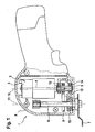
- hand tool 1 comprises in a housing 9 an electric drive motor 2, consisting of a housing-fixed stator 3 and an armature or rotor 4, on the rotatably and coaxially a drive shaft 5 is arranged.
- the rotational movement of the drive shaft 5 is transmitted via an eccentric coupling 8 to an output shaft 6, which carries a tool 7.
- the eccentric coupling 8 By means of the eccentric coupling 8, the rotary movement of the drive shaft 5 is transmitted in a rotary pendulum movement of the output shaft 6.
- the Exzenterkoppel consists of a coupling fork 12 which is rotatably connected to the output shaft 6, and an eccentric cam 13 which is rotatably connected to the drive shaft 5, wherein the coupling fork 12 abuts the contour of the eccentric cam 13, so that relative to the axis of rotation 10 of the drive shaft 5 eccentric movement of the eccentric cam 13 can be scanned by the coupling fork 12 and converted into an oscillating pendulum motion about the axis of rotation 11 of the output shaft 6.
- the eccentric coupling device 8 is adjacent to pivot bearings 14 and 15, respectively, via which the drive shaft 5 and the output shaft 6 are rotatably mounted in the housing 9 on their front side facing the tool 7.
- the components of the eccentric coupling device 8, that is to say the coupling fork 12 and the eccentric cam 13, are thus adjacent to the end face of the respective shafts facing the tool 7.
- the coupling fork 12 as part of the Exzenterkoppel drove 8 two forks 12a and 12b, which include the contour of the eccentric cam 13.
- the section between the fork tines 12a and 12b is expediently part-circular in shape and adapted to the circular shape of the eccentric cam 13, so that an areal contact between the coupling fork 12 and the outer contour of the eccentric cam 13 is given over an angular section.
Landscapes
- Engineering & Computer Science (AREA)
- Mechanical Engineering (AREA)
- Life Sciences & Earth Sciences (AREA)
- Wood Science & Technology (AREA)
- Forests & Forestry (AREA)
- Connection Of Motors, Electrical Generators, Mechanical Devices, And The Like (AREA)
- Finish Polishing, Edge Sharpening, And Grinding By Specific Grinding Devices (AREA)
- Sawing (AREA)
Description
Die Erfindung bezieht sich auf eine motorisch angetriebene Werkzeugmaschine mit einer von einer Antriebseinheit angetriebenen Antriebswelle und einer Abtriebswelle, auf der das Werkzeug aufgenommen ist, nach dem Oberbegriff des Anspruches 1. Eine solche Werkzeugmaschine ist der
In der
Die
Der Schwenkhebel befindet sich im Bereich der dem Werkzeug abgewandten Stirnseite auf der Abtriebswelle. Die Abtriebswelle stellt somit die parallel versetzte, axiale Verlängerung der Rotorwelle dar. Insgesamt ergibt sich dadurch ein verhältnismäßig großer Bauraumbedarf in Achsrichtung.The pivot lever is located in the region of the tool facing away from the end face on the output shaft. The output shaft thus represents the parallel offset, axial extension of the rotor shaft. Overall, this results in a relatively large space requirement in the axial direction.
Von diesem Stand der Technik ausgehend liegt der Erfindung die Aufgabe zugrunde, eine kompakt bauende, motorisch angetriebene Werkzeugmaschine mit pendelnd anzutreibendem Werkzeug anzugeben.Based on this prior art, the invention has for its object to provide a compact, motor-driven machine tool with pendulum to be driven tool.
Diese Aufgabe wird erfindungsgemäß mit den Merkmalen des Anspruches 1 gelöst. Die Unteransprüche geben zweckmäßige Weiterbildungen an.This object is achieved with the features of claim 1. The dependent claims indicate expedient developments.
Die motorisch angetriebene Werkzeugmaschine, bei der es sich insbesondere um eine Handwerkzeugmaschine handelt, deren Werkzeug eine Drehpendelbewegung ausführt, weist parallel zueinander angeordnete Antriebs- und Abtriebswellen auf, wobei zusätzlich vorgesehen ist, dass die Abtriebswelle zumindest teilweise in Höhe der und parallel zur Antriebseinheit verläuft. Auf diese Weise ist sichergestellt, dass sich die Abtriebswelle mit dem Werkzeug unmittelbar neben der Antriebseinheit einschließlich der zur Antriebseinheit gehörenden Antriebswelle befindet, wobei die Werkzeugmaschine aufgrund der axialen Überschneidung von Abtriebswelle und Antriebseinheit in Achsrichtung kurz baut und entsprechend wenig Bauraum beansprucht. Gleiches gilt für die Richtung quer zu den Wellen, da die parallele Anordnung der Abtriebswelle in Querrichtung kaum mehr Platz beansprucht als die Antriebseinheit.The motor-driven machine tool, which is in particular a hand tool whose tool performs a rotary pendulum movement, has parallel to each other arranged input and output shafts, which is additionally provided that the output shaft extends at least partially in height and parallel to the drive unit. In this way, it is ensured that the output shaft with the tool is located directly next to the drive unit including the drive shaft belonging to the drive shaft, the machine tool due to the axial overlap of the output shaft and drive unit in the axial direction builds short and takes up correspondingly little space. The same applies to the direction across the waves, since the parallel arrangement of the output shaft in the transverse direction hardly takes up more space than the drive unit.
Ein weiterer Vorteil der parallelen Anordnung liegt darin, dass die Bewegungsübertragung zwischen Antriebs- und Abtriebswelle aufgrund der parallelen Drehachsen spielfrei oder zumindest mit reduziertem Spiel durchführbar ist. Es ist insbesondere eine linienförmige bzw. flächenförmige Anlage der an der Exzenterkoppeleinrichtung zwischen Antriebs- und Abtriebswelle beteiligten Bauteile aneinander möglich; eine punktförmige Kraftübertragung, die beispielsweise im Stand der Technik bei winklig angeordneten Wellen auftritt und lokal hohe Kraftbelastungen mit der Gefahr erhöhten Spiels aufweist, kann vermieden werden.Another advantage of the parallel arrangement is that the motion transmission between the input and output shaft due to the parallel axes of rotation without play or at least with reduced clearance is feasible. In particular, a linear or planar contact of the components participating in the eccentric coupling device between the input and output shafts is possible with one another; a point-like power transmission, which occurs for example in the prior art at an angle arranged waves and locally high force loads with the risk of increased play can be avoided.
Die Exzenterkoppeleinrichtung umfasst ein Koppelglied und ein Exzenterglied, die jeweils auf unterschiedlichen Wellen angeordnet sind, wobei das Koppelglied bevorzugt auf der Abtriebswelle und das Exzenterglied vorteilhaft auf der Antriebswelle sitzt. Die Drehbewegung des umlaufenden Exzentergliedes wird über das Koppelglied in die Drehpendelbewegung der Abtriebswelle übertragen. Aufgrund der parallelen Anordnung von Antriebs- und Abtriebswelle kann eine linienförmige oder flächige Anlage zwischen Koppelglied und Exzenterglied realisiert werden.The eccentric coupling device comprises a coupling member and an eccentric member, which are each arranged on different shafts, wherein the coupling member preferably on the Output shaft and the eccentric advantageous sitting on the drive shaft. The rotational movement of the revolving eccentric member is transmitted via the coupling member in the rotary pendulum movement of the output shaft. Due to the parallel arrangement of the drive and output shaft, a linear or flat contact between the coupling member and the eccentric member can be realized.
Hierfür ist das Exzenterglied zweckmäßigerweise als Exzenternocken ausgebildet, dessen Kontur von dem Koppelglied abgetastet wird. Das Koppelglied ist beispielsweise gabelförmig ausgeführt, wobei die beiden Gabelzinken das Exzenterglied umgreifen. Die flächige oder linienförmige Anlage zwischen Koppelglied und Exzenterglied erfolgt insbesondere durch teilkreisförmige oder gegebenenfalls auch kreisförmige Ausbildung der aneinanderliegenden Konturen beider Bauteile. Die linienförmige bzw. flächige Anlage erlaubt eine bessere Verteilung der zu übertragenden Kräfte und damit eine geringere punktuelle Belastung.For this purpose, the eccentric member is expediently designed as eccentric cam, whose contour is scanned by the coupling member. The coupling member is designed, for example fork-shaped, wherein the two forks engage around the eccentric member. The planar or linear contact between coupling member and eccentric member is effected in particular by part-circular or possibly also circular formation of the contiguous contours of both components. The linear or planar system allows a better distribution of the forces to be transmitted and thus a lower punctual load.
Gemäß der Erfindung ist das Koppelglied der Koppeleinrichtung benachbart zu dem Werkzeug auf der Abtriebswelle angeordnet. Des Weiteren ist die Antriebseinheit als Elektromotor ausgeführt und der Stator des Elektromotors auf der dem Werkzeug abgewandten Seite im Gehäuse der Werkzeugmaschine angeordnet. Die Positionierung der Koppeleinrichtung auf der dem Werkzeug zugewandten Seite erlaubt eine entsprechend kurze Ausbildung der Abtriebswelle, was dadurch noch unterstützt wird, dass die Antriebswelle sich ebenfalls auf der dem Werkzeug zugewandten Seite befindet und von der Antriebseinheit drehbeaufschlagt wird. In Achsrichtung wird dabei die Bauraumlänge in erster Linie von der Antriebseinheit, also in der Regel von dem Elektromotor bestimmt.According to the invention, the coupling member of the coupling device is arranged adjacent to the tool on the output shaft. Furthermore, the drive unit is designed as an electric motor and the stator of the electric motor is arranged on the side facing away from the tool in the housing of the machine tool. The positioning of the coupling device on the side facing the tool allows a correspondingly short design of the output shaft, which is still supported by the fact that the drive shaft is also located on the side facing the tool and is rotationally urged by the drive unit. In the axial direction, the installation space length is primarily determined by the drive unit, that is, as a rule, by the electric motor.
Weitere Vorteile und zweckmäßige Ausführungen sind den weiteren Ansprüchen, der Figurenbeschreibung und den Zeichnungen zu entnehmen. Es zeigen:
- Fig. 1
- einen Schnitt durch eine Handwerkzeugmaschine, deren Werkzeug eine oszillierende Pendelschwingung zum Sägen und/oder Schleifen ausübt, wobei das Werkzeug an einer Abtriebswelle gehalten ist, die parallel zu einer elektromotorisch angetriebenen Antriebswelle steht,
- Fig. 2
- die Handwerkzeugmaschine in einer perspektivischen Darstellung,
- Fig. 3
- die Exzenterkoppeleinrichtung in Einzeldarstellung, über die die Drehbewegung der elektromotorisch angetriebenen Antriebswelle in die Drehpendelbewegung der das Werkzeug tragenden Abtriebswelle umgesetzt wird.
- Fig. 1
- a section through a hand tool whose tool exerts an oscillating pendulum oscillation for sawing and / or grinding, wherein the tool is held on an output shaft which is parallel to an electric motor driven drive shaft,
- Fig. 2
- the hand tool in a perspective view,
- Fig. 3
- the eccentric coupling device in a single representation, via which the rotational movement of the electric motor-driven drive shaft is converted into the rotary pendulum movement of the tool-carrying output shaft.
In den Figuren sind gleiche Bauteile mit gleichen Bezugszeichen versehen.In the figures, the same components are provided with the same reference numerals.
Die in
Antriebswelle 5 und Abtriebswelle 6 und damit auch die jeweiligen Drehachsen 10 bzw. 11 liegen parallel zueinander im Gehäuse 9. Um eine in Achsrichtung kurz bauende Vorrichtung zu erhalten, erstreckt sich die Abtriebswelle 6 in Achsrichtung gesehen bis in Höhe des Stators 3 des elektrischen Antriebsmotors 2. Man erhält dadurch in Achsrichtung eine teilweise Überdeckung von Abtriebswelle 6 und Stator 3. Die das Werkzeug 7 tragende Stirnseite der Abtriebswelle 6 ragt geringfügig axial aus dem Gehäuse 9 hervor. Die Abtriebswelle 6 überdeckt sich in Achsrichtung gesehen etwa zur Hälfte ihrer Länge mit dem Stator 3.Drive
Die Exzenterkoppeleinrichtung besteht aus einer Koppelgabel 12, die drehfest mit der Abtriebswelle 6 verbunden ist, und einem Exzenternocken 13, der drehfest mit der Antriebswelle 5 verbunden ist, wobei die Koppelgabel 12 an der Kontur des Exzenternockens 13 anliegt, so dass die bezogen auf die Drehachse 10 der Antriebswelle 5 exzentrischen Bewegung des Exzenternockens 13 von der Koppelgabel 12 abgetastet und in eine oszillierende Pendelbewegung um die Drehachse 11 der Abtriebswelle 6 umgesetzt werden kann. Die Exzenterkoppeleinrichtung 8 liegt benachbart zu Drehlagern 14 bzw. 15, über die die Antriebswelle 5 bzw. die Abtriebswelle 6 an ihrer dem Werkzeug 7 zugewandten Stirnseite drehbar im Gehäuse 9 gelagert sind. Die Bauteile der Exzenterkoppeleinrichtung 8, also die Koppelgabel 12 und der Exzenternocken 13, befinden sich somit benachbart zu der dem Werkzeug 7 zugewandten Stirnseite der jeweiligen Wellen.The Exzenterkoppeleinrichtung consists of a
Wie
Claims (4)
- Motor-driven machine tool, in particular hand-operating machine tool (1) having a tool (7) to be driven rotatably, with a driveshaft (5) driven by a drive unit (2) and with an output shaft (6) on which the tool (7) is held, the rotational movement of the driveshaft (5) being convertible via an eccentric coupling device (8) into an oscillating movement of the output shaft (6), the eccentric coupling device (8) comprising a coupling member (12) and an eccentric member (13) which is seated on one of the shafts (5, 6), and the coupling member (12) being operatively connected to the eccentric member (13), the driveshaft and output shaft (5, 6) being arranged parallel to one another, and the output shaft (6) running at least partially level with and parallel to the drive unit (2), the drive unit (2) being assigned as an electric motor, and the stator (3) of the electric motor (2) being arranged, on the side facing away from the tool (7), in the housing (9) of the machine tool (1), characterized in that the coupling member (12) of the eccentric coupling device (8) is arranged adjacently to the tool (7) on the output shaft (6), and in that, as seen in the axial direction, the output shaft (6) is overlapped over about half of its length by the stator (3).
- Machine tool according to Claim 1, characterized in that the eccentric member is designed as an eccentric cam (13) connected fixedly to the driveshaft (5), and in that the coupling member (12) bears against the contour of the eccentric cam (13).
- Machine tool according to Claim 1 or 2, characterized in that the coupling member (12) is of fork-shaped design, the fork prongs (12a, 12b) surrounding the eccentric member (13).
- Machine tool according to Claim 2 or 3, characterized in that the eccentric cam (13) and that portion of the coupling member (12) which bears against the eccentric cam have in each case an at least half-circular contour and bear one against the other at least approximately linearly or areally.
Applications Claiming Priority (2)
| Application Number | Priority Date | Filing Date | Title |
|---|---|---|---|
| DE102007018465A DE102007018465A1 (en) | 2007-04-19 | 2007-04-19 | Motor driven machine tool |
| PCT/EP2008/052011 WO2008128802A1 (en) | 2007-04-19 | 2008-02-19 | Motor-driven machine tool |
Publications (2)
| Publication Number | Publication Date |
|---|---|
| EP2139654A1 EP2139654A1 (en) | 2010-01-06 |
| EP2139654B1 true EP2139654B1 (en) | 2014-04-09 |
Family
ID=39428087
Family Applications (1)
| Application Number | Title | Priority Date | Filing Date |
|---|---|---|---|
| EP08716952.0A Not-in-force EP2139654B1 (en) | 2007-04-19 | 2008-02-19 | Motor-driven machine tool |
Country Status (5)
| Country | Link |
|---|---|
| US (1) | US8096856B2 (en) |
| EP (1) | EP2139654B1 (en) |
| CN (1) | CN101663140B (en) |
| DE (1) | DE102007018465A1 (en) |
| WO (1) | WO2008128802A1 (en) |
Families Citing this family (19)
| Publication number | Priority date | Publication date | Assignee | Title |
|---|---|---|---|---|
| US20110081847A1 (en) * | 2009-10-05 | 2011-04-07 | Tai-Her Yang | Motor parallel transmission portable angle grinder |
| US8925931B2 (en) | 2010-04-29 | 2015-01-06 | Black & Decker Inc. | Oscillating tool |
| US9186770B2 (en) | 2010-04-29 | 2015-11-17 | Black & Decker Inc. | Oscillating tool attachment feature |
| US9073195B2 (en) | 2010-04-29 | 2015-07-07 | Black & Decker Inc. | Universal accessory for oscillating power tool |
| US9149923B2 (en) | 2010-11-09 | 2015-10-06 | Black & Decker Inc. | Oscillating tools and accessories |
| DE102011010745A1 (en) * | 2011-02-09 | 2012-08-09 | Robert Bosch Gmbh | Machine tool with a reciprocating output spindle |
| DE102011015117A1 (en) * | 2011-03-22 | 2012-09-27 | C. & E. Fein Gmbh | hand tool |
| USD832666S1 (en) | 2012-07-16 | 2018-11-06 | Black & Decker Inc. | Oscillating saw blade |
| CN104249340B (en) * | 2013-06-27 | 2017-05-31 | 苏州宝时得电动工具有限公司 | Swing-type power tool |
| CN104249341A (en) * | 2013-06-27 | 2014-12-31 | 苏州宝时得电动工具有限公司 | Swinging power tool |
| DE102014202218A1 (en) * | 2014-02-06 | 2015-08-06 | Robert Bosch Gmbh | Hand tool with an electronically commutated electric motor |
| JP6403589B2 (en) * | 2015-02-02 | 2018-10-10 | 株式会社マキタ | Work tools |
| CN105835012B (en) | 2015-02-02 | 2020-08-21 | 株式会社牧田 | work tool |
| JP6697894B2 (en) * | 2016-02-19 | 2020-05-27 | 株式会社マキタ | Work tools |
| EP3357645B1 (en) | 2016-02-19 | 2019-11-27 | Makita Corporation | Work tool |
| DE102016223508A1 (en) * | 2016-11-28 | 2018-05-30 | Robert Bosch Gmbh | Portable machine tool |
| USD814900S1 (en) | 2017-01-16 | 2018-04-10 | Black & Decker Inc. | Blade for oscillating power tools |
| US10265778B2 (en) | 2017-01-16 | 2019-04-23 | Black & Decker Inc. | Accessories for oscillating power tools |
| EP3385034B1 (en) | 2017-03-29 | 2019-10-16 | Makita Corporation | Work tool |
Family Cites Families (17)
| Publication number | Priority date | Publication date | Assignee | Title |
|---|---|---|---|---|
| US1464351A (en) * | 1923-08-07 | casey | ||
| US2350098A (en) * | 1941-12-31 | 1944-05-30 | Black & Decker Mfg Co | Oscillating sander |
| US2671476A (en) | 1950-02-02 | 1954-03-09 | Syntron Co | Portable belt-driven power handsaw |
| DE7436615U (en) * | 1974-11-02 | 1976-05-06 | Robert Bosch Gmbh, 7000 Stuttgart | IN PARTICULAR HIGH SPEED ORBITAL SANDERS |
| JPS5854961B2 (en) * | 1975-08-03 | 1983-12-07 | 日立工機株式会社 | Shindousetsu Dankougu |
| GB1566025A (en) | 1976-02-14 | 1980-04-30 | Ishihara M | Method and machine for forming a groove in a body of material |
| US4787430A (en) | 1987-02-23 | 1988-11-29 | Ryobi Ltd. | Duplicating router |
| DE4203890C1 (en) * | 1992-02-11 | 1992-10-08 | Fritz Gross Kg Elektrowerkzeuge Und Holzbearbeitungsmaschinen, O-8355 Neustadt, De | Hand-held cutter for sheet metal etc. - has electric micro-motor with eccentric CAM connected to cutting blade shaft |
| CH685154A5 (en) * | 1992-04-21 | 1995-04-13 | Richard E Arnegger | Device for producing dividing cuts |
| US5482499A (en) * | 1993-11-18 | 1996-01-09 | Ryobi Limited | Sanding apparatus |
| EP0829237A3 (en) * | 1996-09-12 | 1998-08-12 | Ricana Ag | Cutting apparatus with a cutting tool on an oscillating drive shaft |
| US5856715A (en) * | 1996-12-13 | 1999-01-05 | Ryobi North America, Inc. | Portable electrical power tool having a rare earth permanent magnet motor |
| US6926595B2 (en) * | 2002-04-30 | 2005-08-09 | C.&E. Fein Gmbh & Co. Kg | Oscillatory drive |
| DE102004047812B4 (en) * | 2004-09-29 | 2022-09-15 | Robert Bosch Gmbh | Grinding hand tool, in particular cordless grinding hand tool |
| DE102004047811A1 (en) * | 2004-09-29 | 2006-03-30 | Robert Bosch Gmbh | Grinding hand tool machine, in particular Akkuschleifhandwerkzeugmaschine |
| DE202004021498U1 (en) | 2004-10-19 | 2008-06-26 | Robert Bosch Gmbh | Device for fastening a tool to an oscillating drivable drive shaft of a hand tool machine |
| JP4525532B2 (en) * | 2005-08-29 | 2010-08-18 | 日立工機株式会社 | Jigsaw |
-
2007
- 2007-04-19 DE DE102007018465A patent/DE102007018465A1/en not_active Withdrawn
-
2008
- 2008-02-19 WO PCT/EP2008/052011 patent/WO2008128802A1/en not_active Ceased
- 2008-02-19 CN CN2008800125885A patent/CN101663140B/en not_active Expired - Fee Related
- 2008-02-19 EP EP08716952.0A patent/EP2139654B1/en not_active Not-in-force
- 2008-02-19 US US12/374,693 patent/US8096856B2/en not_active Expired - Fee Related
Also Published As
| Publication number | Publication date |
|---|---|
| US20100003906A1 (en) | 2010-01-07 |
| WO2008128802A1 (en) | 2008-10-30 |
| US8096856B2 (en) | 2012-01-17 |
| EP2139654A1 (en) | 2010-01-06 |
| CN101663140A (en) | 2010-03-03 |
| CN101663140B (en) | 2012-11-28 |
| DE102007018465A1 (en) | 2008-10-23 |
Similar Documents
| Publication | Publication Date | Title |
|---|---|---|
| EP2139654B1 (en) | Motor-driven machine tool | |
| EP2139647B1 (en) | Motor-driven machine tool | |
| EP2673102B1 (en) | Tool machine with an output spindle that moves back and forth | |
| EP2198691B1 (en) | Work device | |
| DE102007018466A1 (en) | Motor driven machine tool | |
| DE202008001759U1 (en) | Oscillating drivable machine tool | |
| EP2686148A1 (en) | Tool clamping device | |
| DE112009005440B4 (en) | JIGSAW | |
| EP3038780B1 (en) | Counterweight device | |
| DE102009035232B4 (en) | Cutting set for hair clippers | |
| EP2024150B1 (en) | Portable power tool having a tool driven in an oscillating and pendulous manner | |
| WO2012013389A1 (en) | Insert tool | |
| EP2490849B1 (en) | Machine tool | |
| EP2608931A1 (en) | Hand-held machine tool | |
| EP2681023B1 (en) | Machine tool separating device | |
| EP2460758A1 (en) | Hydraulic rotation drive | |
| WO2012116841A1 (en) | Power tool system | |
| EP2890524B1 (en) | Machine tool system | |
| WO2010124777A1 (en) | Gearbox for devices having double rotation tools | |
| EP3946791B1 (en) | Saber saw | |
| EP2527111A1 (en) | Milling machine with an oscillating drive | |
| EP2904893B1 (en) | Hand-held machine tool, in particular a hedge-shear | |
| DE971561C (en) | Agricultural attachment for tractors | |
| DE4203890C1 (en) | Hand-held cutter for sheet metal etc. - has electric micro-motor with eccentric CAM connected to cutting blade shaft | |
| EP1166611A1 (en) | Driving device |
Legal Events
| Date | Code | Title | Description |
|---|---|---|---|
| PUAI | Public reference made under article 153(3) epc to a published international application that has entered the european phase |
Free format text: ORIGINAL CODE: 0009012 |
|
| 17P | Request for examination filed |
Effective date: 20091119 |
|
| AK | Designated contracting states |
Kind code of ref document: A1 Designated state(s): AT BE BG CH CY CZ DE DK EE ES FI FR GB GR HR HU IE IS IT LI LT LU LV MC MT NL NO PL PT RO SE SI SK TR |
|
| 17Q | First examination report despatched |
Effective date: 20100223 |
|
| DAX | Request for extension of the european patent (deleted) | ||
| GRAP | Despatch of communication of intention to grant a patent |
Free format text: ORIGINAL CODE: EPIDOSNIGR1 |
|
| INTG | Intention to grant announced |
Effective date: 20131122 |
|
| GRAS | Grant fee paid |
Free format text: ORIGINAL CODE: EPIDOSNIGR3 |
|
| GRAA | (expected) grant |
Free format text: ORIGINAL CODE: 0009210 |
|
| AK | Designated contracting states |
Kind code of ref document: B1 Designated state(s): AT BE BG CH CY CZ DE DK EE ES FI FR GB GR HR HU IE IS IT LI LT LU LV MC MT NL NO PL PT RO SE SI SK TR |
|
| REG | Reference to a national code |
Ref country code: GB Ref legal event code: FG4D Free format text: NOT ENGLISH |
|
| REG | Reference to a national code |
Ref country code: AT Ref legal event code: REF Ref document number: 661085 Country of ref document: AT Kind code of ref document: T Effective date: 20140415 Ref country code: CH Ref legal event code: EP |
|
| REG | Reference to a national code |
Ref country code: IE Ref legal event code: FG4D Free format text: LANGUAGE OF EP DOCUMENT: GERMAN |
|
| REG | Reference to a national code |
Ref country code: DE Ref legal event code: R096 Ref document number: 502008011569 Country of ref document: DE Effective date: 20140522 |
|
| REG | Reference to a national code |
Ref country code: NL Ref legal event code: VDEP Effective date: 20140409 |
|
| REG | Reference to a national code |
Ref country code: LT Ref legal event code: MG4D |
|
| PG25 | Lapsed in a contracting state [announced via postgrant information from national office to epo] |
Ref country code: FI Free format text: LAPSE BECAUSE OF FAILURE TO SUBMIT A TRANSLATION OF THE DESCRIPTION OR TO PAY THE FEE WITHIN THE PRESCRIBED TIME-LIMIT Effective date: 20140409 Ref country code: NO Free format text: LAPSE BECAUSE OF FAILURE TO SUBMIT A TRANSLATION OF THE DESCRIPTION OR TO PAY THE FEE WITHIN THE PRESCRIBED TIME-LIMIT Effective date: 20140709 Ref country code: IS Free format text: LAPSE BECAUSE OF FAILURE TO SUBMIT A TRANSLATION OF THE DESCRIPTION OR TO PAY THE FEE WITHIN THE PRESCRIBED TIME-LIMIT Effective date: 20140809 Ref country code: BG Free format text: LAPSE BECAUSE OF FAILURE TO SUBMIT A TRANSLATION OF THE DESCRIPTION OR TO PAY THE FEE WITHIN THE PRESCRIBED TIME-LIMIT Effective date: 20140709 Ref country code: NL Free format text: LAPSE BECAUSE OF FAILURE TO SUBMIT A TRANSLATION OF THE DESCRIPTION OR TO PAY THE FEE WITHIN THE PRESCRIBED TIME-LIMIT Effective date: 20140409 Ref country code: LT Free format text: LAPSE BECAUSE OF FAILURE TO SUBMIT A TRANSLATION OF THE DESCRIPTION OR TO PAY THE FEE WITHIN THE PRESCRIBED TIME-LIMIT Effective date: 20140409 Ref country code: GR Free format text: LAPSE BECAUSE OF FAILURE TO SUBMIT A TRANSLATION OF THE DESCRIPTION OR TO PAY THE FEE WITHIN THE PRESCRIBED TIME-LIMIT Effective date: 20140710 |
|
| PG25 | Lapsed in a contracting state [announced via postgrant information from national office to epo] |
Ref country code: ES Free format text: LAPSE BECAUSE OF FAILURE TO SUBMIT A TRANSLATION OF THE DESCRIPTION OR TO PAY THE FEE WITHIN THE PRESCRIBED TIME-LIMIT Effective date: 20140409 Ref country code: LV Free format text: LAPSE BECAUSE OF FAILURE TO SUBMIT A TRANSLATION OF THE DESCRIPTION OR TO PAY THE FEE WITHIN THE PRESCRIBED TIME-LIMIT Effective date: 20140409 Ref country code: SE Free format text: LAPSE BECAUSE OF FAILURE TO SUBMIT A TRANSLATION OF THE DESCRIPTION OR TO PAY THE FEE WITHIN THE PRESCRIBED TIME-LIMIT Effective date: 20140409 Ref country code: HR Free format text: LAPSE BECAUSE OF FAILURE TO SUBMIT A TRANSLATION OF THE DESCRIPTION OR TO PAY THE FEE WITHIN THE PRESCRIBED TIME-LIMIT Effective date: 20140409 Ref country code: PL Free format text: LAPSE BECAUSE OF FAILURE TO SUBMIT A TRANSLATION OF THE DESCRIPTION OR TO PAY THE FEE WITHIN THE PRESCRIBED TIME-LIMIT Effective date: 20140409 |
|
| PG25 | Lapsed in a contracting state [announced via postgrant information from national office to epo] |
Ref country code: PT Free format text: LAPSE BECAUSE OF FAILURE TO SUBMIT A TRANSLATION OF THE DESCRIPTION OR TO PAY THE FEE WITHIN THE PRESCRIBED TIME-LIMIT Effective date: 20140811 |
|
| REG | Reference to a national code |
Ref country code: DE Ref legal event code: R097 Ref document number: 502008011569 Country of ref document: DE |
|
| PG25 | Lapsed in a contracting state [announced via postgrant information from national office to epo] |
Ref country code: RO Free format text: LAPSE BECAUSE OF FAILURE TO SUBMIT A TRANSLATION OF THE DESCRIPTION OR TO PAY THE FEE WITHIN THE PRESCRIBED TIME-LIMIT Effective date: 20140409 Ref country code: DK Free format text: LAPSE BECAUSE OF FAILURE TO SUBMIT A TRANSLATION OF THE DESCRIPTION OR TO PAY THE FEE WITHIN THE PRESCRIBED TIME-LIMIT Effective date: 20140409 Ref country code: CZ Free format text: LAPSE BECAUSE OF FAILURE TO SUBMIT A TRANSLATION OF THE DESCRIPTION OR TO PAY THE FEE WITHIN THE PRESCRIBED TIME-LIMIT Effective date: 20140409 Ref country code: SK Free format text: LAPSE BECAUSE OF FAILURE TO SUBMIT A TRANSLATION OF THE DESCRIPTION OR TO PAY THE FEE WITHIN THE PRESCRIBED TIME-LIMIT Effective date: 20140409 Ref country code: EE Free format text: LAPSE BECAUSE OF FAILURE TO SUBMIT A TRANSLATION OF THE DESCRIPTION OR TO PAY THE FEE WITHIN THE PRESCRIBED TIME-LIMIT Effective date: 20140409 |
|
| PLBE | No opposition filed within time limit |
Free format text: ORIGINAL CODE: 0009261 |
|
| STAA | Information on the status of an ep patent application or granted ep patent |
Free format text: STATUS: NO OPPOSITION FILED WITHIN TIME LIMIT |
|
| 26N | No opposition filed |
Effective date: 20150112 |
|
| PG25 | Lapsed in a contracting state [announced via postgrant information from national office to epo] |
Ref country code: IT Free format text: LAPSE BECAUSE OF FAILURE TO SUBMIT A TRANSLATION OF THE DESCRIPTION OR TO PAY THE FEE WITHIN THE PRESCRIBED TIME-LIMIT Effective date: 20140409 |
|
| REG | Reference to a national code |
Ref country code: DE Ref legal event code: R097 Ref document number: 502008011569 Country of ref document: DE Effective date: 20150112 |
|
| PG25 | Lapsed in a contracting state [announced via postgrant information from national office to epo] |
Ref country code: BE Free format text: LAPSE BECAUSE OF NON-PAYMENT OF DUE FEES Effective date: 20150228 |
|
| PG25 | Lapsed in a contracting state [announced via postgrant information from national office to epo] |
Ref country code: SI Free format text: LAPSE BECAUSE OF FAILURE TO SUBMIT A TRANSLATION OF THE DESCRIPTION OR TO PAY THE FEE WITHIN THE PRESCRIBED TIME-LIMIT Effective date: 20140409 |
|
| PG25 | Lapsed in a contracting state [announced via postgrant information from national office to epo] |
Ref country code: LU Free format text: LAPSE BECAUSE OF FAILURE TO SUBMIT A TRANSLATION OF THE DESCRIPTION OR TO PAY THE FEE WITHIN THE PRESCRIBED TIME-LIMIT Effective date: 20150219 |
|
| REG | Reference to a national code |
Ref country code: CH Ref legal event code: PL |
|
| PG25 | Lapsed in a contracting state [announced via postgrant information from national office to epo] |
Ref country code: LI Free format text: LAPSE BECAUSE OF NON-PAYMENT OF DUE FEES Effective date: 20150228 Ref country code: CH Free format text: LAPSE BECAUSE OF NON-PAYMENT OF DUE FEES Effective date: 20150228 Ref country code: MC Free format text: LAPSE BECAUSE OF FAILURE TO SUBMIT A TRANSLATION OF THE DESCRIPTION OR TO PAY THE FEE WITHIN THE PRESCRIBED TIME-LIMIT Effective date: 20140409 |
|
| REG | Reference to a national code |
Ref country code: IE Ref legal event code: MM4A |
|
| PG25 | Lapsed in a contracting state [announced via postgrant information from national office to epo] |
Ref country code: IE Free format text: LAPSE BECAUSE OF NON-PAYMENT OF DUE FEES Effective date: 20150219 |
|
| REG | Reference to a national code |
Ref country code: FR Ref legal event code: PLFP Year of fee payment: 9 |
|
| REG | Reference to a national code |
Ref country code: AT Ref legal event code: MM01 Ref document number: 661085 Country of ref document: AT Kind code of ref document: T Effective date: 20150219 |
|
| PG25 | Lapsed in a contracting state [announced via postgrant information from national office to epo] |
Ref country code: AT Free format text: LAPSE BECAUSE OF NON-PAYMENT OF DUE FEES Effective date: 20150219 |
|
| PG25 | Lapsed in a contracting state [announced via postgrant information from national office to epo] |
Ref country code: MT Free format text: LAPSE BECAUSE OF FAILURE TO SUBMIT A TRANSLATION OF THE DESCRIPTION OR TO PAY THE FEE WITHIN THE PRESCRIBED TIME-LIMIT Effective date: 20140409 |
|
| REG | Reference to a national code |
Ref country code: FR Ref legal event code: PLFP Year of fee payment: 10 |
|
| PG25 | Lapsed in a contracting state [announced via postgrant information from national office to epo] |
Ref country code: HU Free format text: LAPSE BECAUSE OF FAILURE TO SUBMIT A TRANSLATION OF THE DESCRIPTION OR TO PAY THE FEE WITHIN THE PRESCRIBED TIME-LIMIT; INVALID AB INITIO Effective date: 20080219 |
|
| PG25 | Lapsed in a contracting state [announced via postgrant information from national office to epo] |
Ref country code: CY Free format text: LAPSE BECAUSE OF FAILURE TO SUBMIT A TRANSLATION OF THE DESCRIPTION OR TO PAY THE FEE WITHIN THE PRESCRIBED TIME-LIMIT Effective date: 20140409 |
|
| PG25 | Lapsed in a contracting state [announced via postgrant information from national office to epo] |
Ref country code: TR Free format text: LAPSE BECAUSE OF FAILURE TO SUBMIT A TRANSLATION OF THE DESCRIPTION OR TO PAY THE FEE WITHIN THE PRESCRIBED TIME-LIMIT Effective date: 20140409 |
|
| REG | Reference to a national code |
Ref country code: FR Ref legal event code: PLFP Year of fee payment: 11 |
|
| PGFP | Annual fee paid to national office [announced via postgrant information from national office to epo] |
Ref country code: DE Payment date: 20220426 Year of fee payment: 15 |
|
| PGFP | Annual fee paid to national office [announced via postgrant information from national office to epo] |
Ref country code: FR Payment date: 20230220 Year of fee payment: 16 |
|
| PGFP | Annual fee paid to national office [announced via postgrant information from national office to epo] |
Ref country code: GB Payment date: 20230221 Year of fee payment: 16 |
|
| REG | Reference to a national code |
Ref country code: DE Ref legal event code: R119 Ref document number: 502008011569 Country of ref document: DE |
|
| PG25 | Lapsed in a contracting state [announced via postgrant information from national office to epo] |
Ref country code: DE Free format text: LAPSE BECAUSE OF NON-PAYMENT OF DUE FEES Effective date: 20230901 |
|
| GBPC | Gb: european patent ceased through non-payment of renewal fee |
Effective date: 20240219 |
|
| PG25 | Lapsed in a contracting state [announced via postgrant information from national office to epo] |
Ref country code: GB Free format text: LAPSE BECAUSE OF NON-PAYMENT OF DUE FEES Effective date: 20240219 |
|
| PG25 | Lapsed in a contracting state [announced via postgrant information from national office to epo] |
Ref country code: FR Free format text: LAPSE BECAUSE OF NON-PAYMENT OF DUE FEES Effective date: 20240229 |
|
| PG25 | Lapsed in a contracting state [announced via postgrant information from national office to epo] |
Ref country code: GB Free format text: LAPSE BECAUSE OF NON-PAYMENT OF DUE FEES Effective date: 20240219 Ref country code: FR Free format text: LAPSE BECAUSE OF NON-PAYMENT OF DUE FEES Effective date: 20240229 |