EP2490849B1 - Machine tool - Google Patents
Machine tool Download PDFInfo
- Publication number
- EP2490849B1 EP2490849B1 EP10745606.3A EP10745606A EP2490849B1 EP 2490849 B1 EP2490849 B1 EP 2490849B1 EP 10745606 A EP10745606 A EP 10745606A EP 2490849 B1 EP2490849 B1 EP 2490849B1
- Authority
- EP
- European Patent Office
- Prior art keywords
- slotted
- stroke
- guide
- work tool
- power tool
- Prior art date
- Legal status (The legal status is an assumption and is not a legal conclusion. Google has not performed a legal analysis and makes no representation as to the accuracy of the status listed.)
- Active
Links
- 238000010276 construction Methods 0.000 description 2
- 230000002349 favourable effect Effects 0.000 description 2
- 238000006243 chemical reaction Methods 0.000 description 1
- 125000006850 spacer group Chemical group 0.000 description 1
- 230000007704 transition Effects 0.000 description 1
Images


Classifications
-
- B—PERFORMING OPERATIONS; TRANSPORTING
- B23—MACHINE TOOLS; METAL-WORKING NOT OTHERWISE PROVIDED FOR
- B23D—PLANING; SLOTTING; SHEARING; BROACHING; SAWING; FILING; SCRAPING; LIKE OPERATIONS FOR WORKING METAL BY REMOVING MATERIAL, NOT OTHERWISE PROVIDED FOR
- B23D49/00—Machines or devices for sawing with straight reciprocating saw blades, e.g. hacksaws
- B23D49/10—Hand-held or hand-operated sawing devices with straight saw blades
- B23D49/16—Hand-held or hand-operated sawing devices with straight saw blades actuated by electric or magnetic power or prime movers
- B23D49/162—Pad sawing devices
- B23D49/167—Pad sawing devices with means to adjust the guide plate or with means to adjust the plane in which the saw blade moves
Definitions
- the invention relates to a machine tool, in particular an electric motor driven jigsaw, according to the preamble of claim 1.
- a machine tool is EP 1 598 136 B1 refer to.
- Machine tools in the form of jigsaws with liftable driven saw blade which are operated in several modes, are known in various configurations.
- a rotatability of the lifting blade driven by the lifting movement is provided about a rotation axis parallel to the lifting axis and in which a guide body with a guide slot extending transversely to the lifting axis is provided on the saw blade, into which the crank pin of a crank disk mounted independently of the saw blade intervenes.
- the position of the guide link to the crank pin changes, which requires a certain clearance between these parts.
- such a solution also restricts the constructive freedom with respect to the rotary drive for the rotation of the saw blade about its stroke axis.
- the invention has for its object to design a trained especially as a jigsaw machine with hubbeweglich driven and rotatablymilandem work tool compact and still provide convenient access to the tool for the rotational adjustment and accurate and stable guidance of the tool without affecting the Hubantriebes despite the specver monoen leadership ,
- the supporting support of the link body of the cross thrust crank drive via the guide yoke against the housing avoids undesirable drive influences on the lifting driven working tool as well as corresponding reactions from the working tool on the cross thrust crank drive, which could affect the desired, possible backlash-free lifting guide for the working tool and a corresponding backlash-free operation of the cross thrust crank drive ,
- the rotatability of the working tool is made possible not only in structurally favorable manner by this configuration, but also without repercussions on the taking place via the cross-thrust crank drive the working tool.
- the guide yoke and the link body rotatably supported each other if necessary, be integrally formed, so that even for the link body despite the plane offset to the yoke ultimately a quasi-immediate support is given to the housing.
- the pivot also offers particularly favorable conditions for access to the necessary for the working tool rotary drive to the working tool.
- This also in machine tools that are designed as jigsaws and where the serving as a working tool, driven liftable saw blade in the so-called Pendelhub shall in the direction of the saw blade plane is pivotally superimposed driven to the linear actuator, since in such a configuration, the required, transverse to the lifting axis support of the working tool , Or a lifting rod carrying the working tool, can be articulated directly on the pivot pin via a corresponding pivot connection, such as a pivot pin.
- An axially spaced access to the guide yoke of the rotary drive on the working tool, in particular in its design as a saw blade can be realized in the described basic construction in an advantageous manner via a pivot pin axially spaced Drehabstützung, which is preferably formed by a housing side supported bearing, the one Having based on the rotatability about the lifting axis supporting sliding guide for the non-circular cross-section, in particular rectangular cross-section, having lifting rod.
- this sliding guide is preferably designed as extending in pendulum direction slot guide with given to the lifting rod excess in pendulum direction.
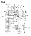
- the Fig. 1 to 4 illustrate, reduced to the essentials, drive and guide for the working tool 1 of a machine tool 2, which is designed as a jigsaw 3 and which has a jigsaw blade 4 as a working tool 1.
- a machine tool 2 which is designed as a jigsaw 3 and which has a jigsaw blade 4 as a working tool 1.
- jigsaws In connection with the generally known construction of jigsaws, one has vorzusilen the solution shown in the figures for drive and leadership embedded in the structure of the jigsaw, which is supported by a foot plate to the workpiece and enclosed in the drive and guide for the working tool in the housing side , are arranged with respect to the working direction front part of the machine housing, as for example, the above-mentioned in the prior art documents show.
- FIG. 1 to 4 the illustrations go according to Fig. 1 to 4 from a support frame 5, which is connected to a housing, not shown, against which the crank disk 7 of a cross thrust crank drive 8 is supported, whose crank pin 9 carries a bearing 10 and engages in the guide slot 11 of a guide body 12 via this bearing 10.
- the link body 12 with the guide slot 11 extends in a plane 13 which is the same direction to a plane 14 in which the lifting axis 15 of the working tool 1 forming saw blade 4 extends, wherein the plane 13 is offset transversely to the lifting axis 15.
- the mass balance serves a arranged on an eccentric collar of the crank disc 7, lying in the transition from the support frame 5 on the crank disc 7 disc-shaped balance weight 36th
- lifting rod 16 In the connection of the jigsaw blade 4 to the cross thrust crank drive 8 extending in the direction of the lifting axis 15 lifting rod 16 is provided in the known manner, on the one hand expires in a receptacle for the respective saw blade 4 and on the other hand supported against a guide yoke 17 and this guide yoke 17 in Direction of the lifting plane 14 slidably guided to the housing is fixed.
- the guide relative to the housing takes place on the housing side supported sliding guides 18, in which the guide yoke 17 extends over laterally projecting lugs 19, between which the central support 20 of the lifting rod 16, and thus the saw blade 4 to the guide yoke 17.
- the central support 20 is formed in the embodiment by a pivot pin 21 which passes through the guide yoke 17 in a central, provided in its central part 22 opening.
- the guide yoke 17 extends with its laterally projecting lugs 19 and these receiving sliding guides 18 in the lifting plane 14, which is parallel to the lifting plane 13, in which the guide slot 11 of the link body extends.
- the link body 12 is provided with a spacer 23 bridging the distance between the lifting planes 13 and 14, against which the guide yoke 17 is supported in the region of its middle part 22.
- the boom 23 is formed by two spaced apart in the direction of the lifting axis 15 fork arms 24, which are provided transversely to the extension direction of the guide slot 11 opposite each other on the crank body 12.
- the gate body 12 and the guide yoke 17 separate parts, which are connected via the pivot pin 21, which carries the saw blade 4 via the lifting rod 16 and is in the drive. In principle, however, it is also within the scope of the invention to connect the guide yoke 17 integrally with the link body 12.
- the support 25 preferably has a enclosing to a Unrundquerrough having lifting rod 16 provided bearing body 26, via which the lifting rod 16 in the stroke direction as well as transversely to the working plane of the lifting rod 16 carried by the saw blade 4, and thus also transversely to the lifting axis 15 is guided.
- the relevant drive is not shown in the embodiment, but can be done in the form shown in the prior art - is the Lifting rod 16 connected to a transverse to the lifting axis 15 pivot axis 27 with the pivot pin 21.
- the transverse guidance of the lifting direction in the pendulum direction 28 adjustable lifting rod at a non-circular profile of the lifting rod 16 parallel to the pendulum direction 28 extending flanks via a slot guide 29 in the bearing 26, wherein the slot guide 29 in the direction of travel 28 to the cross section of the lifting rod 16 corresponding Excessive.
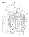
- the for the rotation of the working tool 1, in particular in the form of the saw blade 4, required rotary drive, in the Fig. 3 and 4 symbolically indicated by the arrow 30, can preferably attack on the pivot pin 21 or on the bearing 26, so that in this respect already given components can also be used to transfer the introduced via the rotary drive torque to the working tool 1.
- the pivot pin 21 offers many opportunities for the attack of a corresponding rotary drive.
- Fig. 3 is a related structural solution for a rotary drive 30 schematically indicated at 31.
- the symbolically indicated by the arrow 30 rotary actuator is in the embodiment according to Fig. 4 as a rotary drive 39 on the pivot pin 21 at.
- the pivot pin 21 is provided with a laterally projecting lever arm 32.
- the lever arm 32 engages a coaxial with the pivot pin 21 fixed rotary arm 33 of a connecting member 34.
- the rotary arm 33 extends in the direction of the lifting axis 15 and has a running in the direction of the lifting axis 15 backdrop 35, so that a fixed to the housing, not shown drive regardless of the lifting movement for the rotary drive of the working tool 1 can be used.
- the embodiment according to Fig. 4 illustrates that even with access of the rotary drive on the pivot pin 21 a simple design of the corresponding drive connection is possible.
- a acting on the connecting member 34, symbolized by the arrow 30 rotary drive can also engage a lying in the direction of the lifting axis 15 drive pin 38 of the connecting member 34, wherein an associated drive motor in the axial extension of the drive pin 38 fixed at axially displaceable connection to the drive pin 38 is provided can be. Also, a radial access of a housing side supported drive on the drive pin is possible, so that different drive concepts 38 can be provided with the same basic structure.
Description
Die Erfindung betrifft eine Werkzeugmaschine, insbesondere eine elektromotorisch angetriebene Stichsäge, gemäß dem Oberbegriff des Anspruches 1. Eine solche Werkzeugmaschine ist der
Werkzeugmaschinen in Form von Stichsägen mit hubbeweglich angetriebenem Sägeblatt, die in mehreren Betriebsweisen zu betreiben sind, sind in verschiedenen Ausgestaltungen bekannt. So beispielsweise aus der
Für Werkzeugmaschinen in Form von Stichsägen, die keine Verdrehbarkeit des Sägeblattes um dessen jeweilige Hubachse vorsehen, ist es des Weiteren aus der
Der Erfindung liegt die Aufgabe zugrunde, eine insbesondere als Stichsäge ausgebildete Werkzeugmaschine mit hubbeweglich angetriebenen und drehbar anzutreibendem Arbeitswerkzeug kompakt auszubilden und trotzdem günstige Zugriffsmöglichkeiten auf das Werkzeug zu dessen Drehverstellung sowie eine exakte und stabile Führung des Werkzeuges ohne Beeinträchtigung des Hubantriebes trotz der drehverstellbaren Führung zu gewährleisten.The invention has for its object to design a trained especially as a jigsaw machine with hubbeweglich driven and rotatably anzutreibendem work tool compact and still provide convenient access to the tool for the rotational adjustment and accurate and stable guidance of the tool without affecting the Hubantriebes despite the drehverstellbaren leadership ,
Erreicht wird dies erfindungsgemäß mit den Merkmalen des Anspruches 1. Die weiteren Ansprüche beinhalten zweckmäßige Ausgestaltungen.This is achieved according to the invention with the features of claim 1. The other claims include expedient embodiments.
Dadurch, dass das Arbeitswerkzeug drehbar über ein Führungsjoch gehalten ist, das seinerseits in Hubrichtung des Arbeitswerkzeuges verschieblich gehäuseseitig geführt ist, ist erfindungsgemäß die Möglichkeit geschaffen, abgestützt zum Führungsjoch und ebenenversetzt zu diesem unabhängig vom Arbeitswerkzeug den Führungskörper mit der Führungskulisse anzuordnen, in die der Kurbelzapfen des Kreuzschubkurbeltriebs eingreift, über den das Arbeitswerkzeug hubbeweglich anzutreiben ist. Die tragende Abstützung des Kulissenkörpers des Kreuzschubkurbeltriebes über das Führungsjoch gegen das Gehäuse vermeidet unerwünschte Antriebseinflüsse auf das hubbeweglich angetriebene Arbeitswerkzeug ebenso wie entsprechende Rückwirkungen vom Arbeitswerkzeug auf den Kreuzschubkurbeltrieb, die die angestrebte, möglichst spielfreie Hubführung für das Arbeitswerkzeug und eine entsprechend spielfreie Arbeitsweise des Kreuzschubkurbeltriebs beeinflussen könnten. Weiter wird durch diese Ausgestaltung die Verdrehbarkeit des Arbeitswerkzeuges nicht nur in baulich günstiger Weise ermöglicht, sondern auch ohne Rückwirkungen auf den über den Kreuzschubkurbeltrieb erfolgenden Antrieb des Arbeitswerkzeuges.Characterized in that the working tool is rotatably supported by a guide yoke, which in turn is displaceably guided in the lifting direction of the working tool on the housing side, according to the invention provides the possibility supported to the guide yoke and plane offset to this independent of the working tool to arrange the guide body with the guide slot, in which the crank pin engages the cross-thrust crank drive, via which the working tool is driven to lift. The supporting support of the link body of the cross thrust crank drive via the guide yoke against the housing avoids undesirable drive influences on the lifting driven working tool as well as corresponding reactions from the working tool on the cross thrust crank drive, which could affect the desired, possible backlash-free lifting guide for the working tool and a corresponding backlash-free operation of the cross thrust crank drive , Next, the rotatability of the working tool is made possible not only in structurally favorable manner by this configuration, but also without repercussions on the taking place via the cross-thrust crank drive the working tool.
Bei der erfindungsgemäßen Ausgestaltung können das Führungsjoch und der Kulissenkörper drehfest aufeinander abgestützt, gegebenenfalls auch einstückig ausgebildet sein, so dass auch für den Kulissenkörper trotz des Ebenenversatzes zum Führungsjoch letztlich eine quasi unmittelbare Abstützung zum Gehäuse gegeben ist.In the embodiment according to the invention, the guide yoke and the link body rotatably supported each other, if necessary, be integrally formed, so that even for the link body despite the plane offset to the yoke ultimately a quasi-immediate support is given to the housing.
Als besonders zweckmäßig erweist sich aber eine Ausgestaltung, bei der das Führungsjoch und der Kulissenkörper um die Hubachse des Arbeitswerkzeuges, ungeachtet der gegebenen axialen Abstützung in Hubrichtung, drehbeweglich aufeinander abgestützt sind, so dass eine um die Drehachse entkoppelte Führung des Kulissenkörpers über das Führungsjoch realisiert ist.Particularly expedient, however, turns out to be an embodiment in which the guide yoke and the link body about the lifting axis of the working tool, regardless of the given axial support in the stroke direction, are rotatably supported on each other, so that a decoupled about the axis of rotation guidance of the link body is realized on the guide yoke ,
In besonders einfacher Weise lässt sich dies dadurch gestalten, dass der Kulissenkörper über einen Ausleger mit dem Führungsjoch verbunden ist, wobei das Führungsjoch bevorzugt zwischen Gabelarmen des Auslegers in Hubrichtung abgestützt ist und die Drehbeweglichkeit über einen Drehbolzen erreicht wird, der um die Hubachse des Arbeitswerkzeuges drehbar Kulissenkörper und Führungsjoch verbindet und zugleich die um die Hubachse drehbare Verbindung des Arbeitswerkzeuges zum Führungsjoch bildet.In a particularly simple manner, this can be achieved in that the link body is connected via a boom with the guide yoke, wherein the guide yoke is preferably supported between fork arms of the boom in the stroke direction and the rotational mobility is achieved via a pivot pin which is rotatable about the stroke axis of the working tool Connecting link body and guide yoke and at the same time forms the rotatable about the lifting axis connection of the working tool to the guide yoke.
Damit wird praktisch ohne Zusatzaufwand die Drehbarkeit des Arbeitswerkzeuges realisiert, wobei der Drehbolzen auch besonders günstige Voraussetzungen für den Zugriff des für das Arbeitswerkzeug notwendigen Drehantriebs auf das Arbeitswerkzeug bietet. Dies auch bei Werkzeugmaschinen, die als Stichsägen gestaltet sind und bei denen das als Arbeitswerkzeug dienende, hubbeweglich angetriebene Sägeblatt im sogenannten Pendelhubbetrieb in Richtung der Sägeblattebene verschwenkbar überlagert zum Hubantrieb angetrieben ist, da bei einer solchen Ausgestaltung die erforderliche, quer zur Hubachse schwenkbare Abstützung des Arbeitswerkzeuges, oder einer das Arbeitswerkzeug tragenden Hubstange, über eine entsprechende Schwenkverbindung, etwa einen Schwenkbolzen unmittelbar am Drehbolzen angelenkt sein kann.Thus, the rotation of the working tool is realized practically without additional effort, the pivot also offers particularly favorable conditions for access to the necessary for the working tool rotary drive to the working tool. This also in machine tools that are designed as jigsaws and where the serving as a working tool, driven liftable saw blade in the so-called Pendelhubbetrieb in the direction of the saw blade plane is pivotally superimposed driven to the linear actuator, since in such a configuration, the required, transverse to the lifting axis support of the working tool , Or a lifting rod carrying the working tool, can be articulated directly on the pivot pin via a corresponding pivot connection, such as a pivot pin.
Auch ein zum Führungsjoch axial beabstandeter Zugriff des Drehantriebes auf das Arbeitswerkzeug, insbesondere in dessen Ausgestaltung als Sägeblatt, lässt sich bei der geschilderten Grundkonstruktion in vorteilhafter Weise über eine zum Drehbolzen axial beabstandete Drehabstützung realisieren, die bevorzugt durch ein gehäuseseitig abgestütztes Lager gebildet ist, das eine bezogen auf die Verdrehbarkeit um die Hubachse abstützende Gleitführung für die Unrundquerschnitt, insbesondere Rechteckquerschnitt, aufweisende Hubstange aufweist. Im Hinblick auf eine zusätzliche Realisierung des Pendelantriebes ist diese Gleitführung bevorzugt als sich in Pendelrichtung erstreckende Langlochführung mit zur Hubstange gegebenem Übermaß in Pendelrichtung gestaltet.An axially spaced access to the guide yoke of the rotary drive on the working tool, in particular in its design as a saw blade can be realized in the described basic construction in an advantageous manner via a pivot pin axially spaced Drehabstützung, which is preferably formed by a housing side supported bearing, the one Having based on the rotatability about the lifting axis supporting sliding guide for the non-circular cross-section, in particular rectangular cross-section, having lifting rod. With regard to an additional realization of the pendulum drive, this sliding guide is preferably designed as extending in pendulum direction slot guide with given to the lifting rod excess in pendulum direction.
Weitere Einzelheiten und Merkmale der Erfindung ergeben sich aus den Ansprüchen, den Ausführungsbeispielen und deren Beschreibung. Es zeigen:
- Fig. 1
- eine perspektivische und auf den Grundaufbau für Antrieb und Führung des Arbeitswerkzeuges beschränkte, schematisierte Darstellung einer als Stichsäge ausgestalteten Werkzeugmaschine,
- Fig. 2 und 3
- weitere Ansichten zur Darstellung gemäß
Fig. 1 , und - Fig. 4
- eine im Wesentlichen der
Fig. 1 entsprechende Schemadarstellung, die ergänzend eine mögliche Ausgestaltung einer auf den Drehbolzen zugreifenden Antriebsverbindung des Drehantriebes für das Arbeitswerkzeug zeigt.
- Fig. 1
- a perspective and limited to the basic structure for driving and guiding the working tool, schematic representation of a designed as a jigsaw machine tool,
- FIGS. 2 and 3
- further views for illustration according to
Fig. 1 , and - Fig. 4
- a substantially the
Fig. 1 corresponding schematic representation, which shows a possible embodiment of an access to the pivot pin drive connection of the rotary drive for the working tool.
Die
Bezogen auf eine solche Gestaltung gehen die Darstellungen gemäß
In der Verbindung des Stichsägeblattes 4 zum Kreuzschubkurbeltrieb 8 ist im Ausführungsbeispiel eine in Richtung der Hubachse 15 verlaufende Hubstange 16 vorgesehen, die in bekannter Weise einerseits in einer Aufnahme für das jeweilige Sägeblatt 4 ausläuft und andererseits gegen ein Führungsjoch 17 abgestützt und über dieses Führungsjoch 17 in Richtung der Hubebene 14 verschieblich geführt zum Gehäuse festgelegt ist. Die Führung gegenüber dem Gehäuse erfolgt über gehäuseseitig abgestützte Schiebeführungen 18, in denen das Führungsjoch 17 über seitlich auskragende Ansätze 19 läuft, zwischen denen die zentrale Abstützung 20 der Hubstange 16, und damit des Sägeblattes 4 zum Führungsjoch 17 liegt. Die zentrale Abstützung 20 ist im Ausführungsbeispiel durch einen Drehbolzen 21 gebildet, der das Führungsjoch 17 in einer zentralen, in seinem Mittelteil 22 vorgesehenen Öffnung durchsetzt.In the connection of the jigsaw blade 4 to the cross
Im Ausführungsbeispiel erstreckt sich das Führungsjoch 17 mit seinen seitlich auskragenden Ansätzen 19 und den diese aufnehmenden Schiebeführungen 18 in der Hubebene 14, die parallel zur Hubebene 13 liegt, in der die Führungskulisse 11 des Kulissenkörpers verläuft. Der Kulissenkörper 12 ist mit einem den Abstand zwischen den Hubebenen 13 und 14 überbrückenden Aus!eger 23 versehen, gegen den das Führungsjoch 17 im Bereich seines Mittelteiles 22 abgestützt ist. Der Ausleger 23 wird durch zwei in Richtung der Hubachse 15 beabstandet liegende Gabelarme 24 gebildet, welche quer zur Erstreckungsrichtung der Führungskulisse 11 einander gegenüberliegend am Kulissenkörper 12 vorgesehen sind. Im Ausführungsbeispiel bilden der Kulissenkörper 12 und das Führungsjoch 17 voneinander getrennte Teile, die über den Drehbolzen 21 verbunden sind, der über die Hubstange 16 das Sägeblatt 4 trägt und in dessen Antrieb liegt. Grundsätzlich liegt es aber auch im Rahmen der Erfindung, das Führungsjoch 17 mit dem Kulissenkörper 12 einstückig zu verbinden.In the exemplary embodiment, the
Für die in der Verbindung des Drehbolzens 21 zum Sägeblatt 4 liegende Hubstange 16 ist beabstandet zum Führungsjoch 17 und in Richtung auf das Sägeblatt 4 versetzt eine zusätzlich lagernde Abstützung 25 gegen den Tragrahmen 5 vorgesehen. Die Abstützung 25 weist bevorzugt einen umschließend zur einen Unrundquerschnitt aufweisenden Hubstange 16 vorgesehenen Lagerkörper 26 auf, über den die Hubstange 16 in Hubrichtung wie auch quer zur Arbeitsebene des von der Hubstange 16 getragenen Sägeblattes 4, und damit auch quer zur Hubachse 15 geführt ist. Im Hinblick auf die Realisierung eines Pendelhubbetriebes, bei dem das Arbeitswerkzeug 1 in Form des Sägeblattes 4 zusätzlich in Sägerichtung pendelnd angetrieben ist, - der diesbezügliche Antrieb ist im Ausführungsbeispiel nicht dargestellt, kann aber in der aus dem Stand der Technik ersichtlichen Form erfolgen - ist die Hubstange 16 um eine quer zur Hubachse 15 verlaufende Schwenkachse 27 mit dem Drehbolzen 21 verbunden. Über das Lager 26 erfolgt die Querführung der zusätzlich zur Hubrichtung in Pendelrichtung 28 verstellbaren Hubstange bei einem Unrundprofil der Hubstange 16 mit parallel zur Pendelrichtung 28 verlaufenden Flanken über eine Langlochführung 29 im Lager 26, wobei die Langlochführung 29 in Pendelrichtung 28 zum Querschnitt der Hubstange 16 entsprechendes Übermaß aufweist.For the
Der für die Verdrehung des Arbeitswerkzeuges 1, insbesondere in Form des Sägeblattes 4, erforderliche Drehantrieb, der in den
Der Zugriff des Drehantriebes 30 auf das Lager 26 bietet zusätzliche Vorteile, da das Lager 26 unabhängig von der jeweiligen Hubstellung des Arbeitswerkzeuges 1 seine Lage zum Gehäuse zumindest im Wesentlichen beibehält, womit sich auch ein linearer Antrieb mit gehäuseseitiger Abstützung mit Vorteil nutzen lässt. In
Der über den Pfeil 30 symbolisch angedeutete Drehantrieb setzt in der Ausgestaltung gemäß
Ein auf das Verbindungsglied 34 wirkender, über den Pfeil 30 symbolisierter Drehantrieb kann allerdings auch an einem in Richtung der Hubachse 15 liegenden Antriebszapfen 38 des Verbindungsgliedes 34 angreifen, wobei ein zugehöriger Antriebsmotor in axialer Verlängerung des Antriebszapfens 38 feststehend bei axialer verschieblicher Verbindung zum Antriebszapfen 38 vorgesehen sein kann. Auch ein radialer Zugriff eines gehäuseseitig abgestützten Antriebes auf den Antriebszapfen ist möglich, so dass bei gleichem Grundaufbau unterschiedliche Antriebskonzepte 38 vorgesehen werden können.A acting on the connecting
Claims (12)
- Power tool, in particular a jigsaw (3) driven by an electric motor, having a work tool (1) that is rotationally adjustable about its stroke axis (15) located in a stroke plane (14), said work tool (1) being driven in the stroke direction via a Scotch-yoke crank mechanism (8), the crank pin (9) of which engages in a slotted guide link (11), extending transversely to the stroke axis (15), of a slotted-link body (12) that is movable in a reciprocating manner together with the work tool (1) in the direction of extent of the stroke axis (15), the slotted guide link (11) of said slotted-link body (12) and the stroke axis (15) of the work tool (1) extending in mutually offset, identically oriented, in particular parallel stroke planes (13, 14), characterized in that the work tool (1) is held in a rotatable manner via a guide yoke (17) which carries the slotted-link body (12) having the slotted guide link (11) and is guided in a sliding manner on the housing side in the direction of extent of the stroke plane (14) containing the stroke axis (15) of the work tool (1).
- Power tool according to Claim 1, characterized in that the guide yoke (17) and the slotted-link body (12) are supported in a rotationally locked manner on one another.
- Power tool according to Claim 1, characterized in that the guide yoke (17) and the slotted-link body (12) form separate components or are formed integrally.
- Power tool according to Claim 1, characterized in that the guide yoke (17) and the slotted-link body (12) are supported on one another in a rotatable manner about the stroke axis (15) of the work tool (1).
- Power tool according to one of the preceding claims, characterized in that the slotted-link body (12) is connected to the guide yoke (17) via a cantilever (23).
- Power tool according to Claim 5, characterized in that the guide yoke (17) is supported in the stroke direction between fork arms (24) of the cantilever (23) of the slotted-link body (12).
- Power tool according to Claims 4 to 6, characterized in that the work tool (1), the slotted-link body (12) and the guide yoke (17) are connected rotatably about the stroke axis (15) of the work tool (1) via a pivot pin (21) and are supported against one another.
- Power tool according to one of the preceding claims, characterized in that the work tool (1) is connected to the pivot pin (21) about a pivot axis (27) that extends transversely to the stroke axis (15).
- Power tool according to Claim 7 or 8, characterized in that the work position of the work tool (1) is settable via the pivot pin (21).
- Power tool according to Claim 9, characterized in that the rotary drive (arrow 30) for the work tool (1) acts on the pivot pin (21).
- Power tool according to Claim 9 or 10, characterized in that the pivot pin (21) is connected to a rotary arm (33) that is located in a manner offset laterally with respect to the stroke axis (15) and extends in the direction of the stroke axis (15), the rotary drive (39) acting on said rotary arm (33) in a longitudinally displaceable manner in the direction of the stroke axis (15) in a manner guided by a slotted link.
- Power tool according to one of the preceding claims, characterized in that the work tool (1) is guided in a reciprocating manner in the direction of its stroke axis (15) in a manner offset to the guide yoke (17) in a rotary bearing (26) on which the rotary drive (arrow 30) for the work tool (1) acts.
Applications Claiming Priority (3)
| Application Number | Priority Date | Filing Date | Title |
|---|---|---|---|
| DE102009045954 | 2009-10-23 | ||
| DE102009046374A DE102009046374A1 (en) | 2009-10-23 | 2009-11-04 | machine tool |
| PCT/EP2010/062208 WO2011047904A1 (en) | 2009-10-23 | 2010-08-23 | Machine tool |
Publications (2)
| Publication Number | Publication Date |
|---|---|
| EP2490849A1 EP2490849A1 (en) | 2012-08-29 |
| EP2490849B1 true EP2490849B1 (en) | 2013-05-29 |
Family
ID=43796664
Family Applications (1)
| Application Number | Title | Priority Date | Filing Date |
|---|---|---|---|
| EP10745606.3A Active EP2490849B1 (en) | 2009-10-23 | 2010-08-23 | Machine tool |
Country Status (5)
| Country | Link |
|---|---|
| EP (1) | EP2490849B1 (en) |
| CN (1) | CN102596469B (en) |
| DE (1) | DE102009046374A1 (en) |
| RU (1) | RU2543115C2 (en) |
| WO (1) | WO2011047904A1 (en) |
Families Citing this family (5)
| Publication number | Priority date | Publication date | Assignee | Title |
|---|---|---|---|---|
| DE102010018685B4 (en) * | 2010-04-29 | 2015-09-24 | Uwe Hartmann | scroll saw |
| US9573207B2 (en) * | 2013-05-09 | 2017-02-21 | Makita Corporation | Reciprocating cutting tool |
| US10835972B2 (en) | 2018-03-16 | 2020-11-17 | Milwaukee Electric Tool Corporation | Blade clamp for power tool |
| US11014176B2 (en) | 2018-04-03 | 2021-05-25 | Milwaukee Electric Tool Corporation | Jigsaw |
| USD887806S1 (en) | 2018-04-03 | 2020-06-23 | Milwaukee Electric Tool Corporation | Jigsaw |
Family Cites Families (9)
| Publication number | Priority date | Publication date | Assignee | Title |
|---|---|---|---|---|
| SU501868A1 (en) * | 1974-06-21 | 1976-02-05 | Горьковский Автомобильный Завод | Pneumatic saw |
| US4272996A (en) * | 1979-06-19 | 1981-06-16 | Black & Decker Inc. | Scotch yoke having a curved track |
| US4262420A (en) * | 1979-12-14 | 1981-04-21 | The Singer Company | Crosshead for sabre saws and sabre saws incorporating same |
| DE3702670A1 (en) | 1986-12-18 | 1988-08-11 | Licentia Gmbh | Jigsaw with a plunger stroke movement produced by a Scotch-yoke mechanism |
| US5724741A (en) * | 1996-03-12 | 1998-03-10 | Milwaukee Electric Tool Corporation | Reciprocating saw with pivoting shoe |
| JP3710697B2 (en) | 2000-09-19 | 2005-10-26 | 株式会社マキタ | Reciprocating cutting tool |
| GB2393934A (en) * | 2002-10-07 | 2004-04-14 | Black & Decker Inc | A reciprocating saw with two eccentrics |
| DE602004002572T2 (en) | 2004-05-18 | 2007-07-12 | Black & Decker Inc., Newark | Arrangement of an output ram and motorized tool with such an arrangement |
| RU55324U1 (en) * | 2006-03-13 | 2006-08-10 | Общество с ограниченной ответственностью "Инструментальная компания ЭНКОР" | TABLE ELECTRIC Jigsaw |
-
2009
- 2009-11-04 DE DE102009046374A patent/DE102009046374A1/en not_active Withdrawn
-
2010
- 2010-08-23 WO PCT/EP2010/062208 patent/WO2011047904A1/en active Application Filing
- 2010-08-23 EP EP10745606.3A patent/EP2490849B1/en active Active
- 2010-08-23 CN CN201080047855.XA patent/CN102596469B/en active Active
- 2010-08-23 RU RU2012120902/02A patent/RU2543115C2/en not_active IP Right Cessation
Also Published As
| Publication number | Publication date |
|---|---|
| RU2543115C2 (en) | 2015-02-27 |
| WO2011047904A1 (en) | 2011-04-28 |
| DE102009046374A1 (en) | 2011-04-28 |
| RU2012120902A (en) | 2013-11-27 |
| CN102596469B (en) | 2015-02-11 |
| CN102596469A (en) | 2012-07-18 |
| EP2490849A1 (en) | 2012-08-29 |
Similar Documents
| Publication | Publication Date | Title |
|---|---|---|
| DE102007039580B4 (en) | Drive mechanism for a motor foxtail | |
| EP2161376B1 (en) | Mobile joint cutter | |
| DE4108982B4 (en) | Swash plate drive | |
| EP2139654B1 (en) | Motor-driven machine tool | |
| EP2490849B1 (en) | Machine tool | |
| EP0175643B1 (en) | Drill stand with guide bar | |
| EP1320437B1 (en) | Saw with a tool guidance mechanism with guide elements adjustable to the tool size | |
| WO2010076082A2 (en) | Motor-driven machine tool | |
| DE102017116823A1 (en) | Oscillating powered machine tool | |
| EP3038779B1 (en) | Jigsaw transmission | |
| EP2384252A1 (en) | Motor-driven machine tool | |
| EP2532462A1 (en) | Motorised hand-held saw | |
| EP1980351A2 (en) | Hacksaw machine | |
| EP1955802B1 (en) | Hacksaw, in particular jig saw | |
| DE102008001769A1 (en) | Machine tool, in particular hand-held machine tool | |
| WO2013053351A1 (en) | Mowing device | |
| EP0478823B1 (en) | Honing machine | |
| EP2029304B1 (en) | Jigsaw machine with saw blade and guide device | |
| DE2839449A1 (en) | STRAND CUTTING MACHINE | |
| DE19804706B4 (en) | Hand-held jigsaw machine | |
| WO2010076080A2 (en) | Motor-driven machine tool | |
| DE1502970B2 (en) | Flat knife hemming scissors | |
| WO2009138272A1 (en) | Power tool, especially hand-held power tool | |
| DE102008001772A1 (en) | Machine tool, in particular hand-held machine tool | |
| DE4203890C1 (en) | Hand-held cutter for sheet metal etc. - has electric micro-motor with eccentric CAM connected to cutting blade shaft |
Legal Events
| Date | Code | Title | Description |
|---|---|---|---|
| PUAI | Public reference made under article 153(3) epc to a published international application that has entered the european phase |
Free format text: ORIGINAL CODE: 0009012 |
|
| 17P | Request for examination filed |
Effective date: 20120523 |
|
| AK | Designated contracting states |
Kind code of ref document: A1 Designated state(s): AL AT BE BG CH CY CZ DE DK EE ES FI FR GB GR HR HU IE IS IT LI LT LU LV MC MK MT NL NO PL PT RO SE SI SK SM TR |
|
| DAX | Request for extension of the european patent (deleted) | ||
| GRAP | Despatch of communication of intention to grant a patent |
Free format text: ORIGINAL CODE: EPIDOSNIGR1 |
|
| GRAS | Grant fee paid |
Free format text: ORIGINAL CODE: EPIDOSNIGR3 |
|
| GRAA | (expected) grant |
Free format text: ORIGINAL CODE: 0009210 |
|
| AK | Designated contracting states |
Kind code of ref document: B1 Designated state(s): AL AT BE BG CH CY CZ DE DK EE ES FI FR GB GR HR HU IE IS IT LI LT LU LV MC MK MT NL NO PL PT RO SE SI SK SM TR |
|
| REG | Reference to a national code |
Ref country code: GB Ref legal event code: FG4D Free format text: NOT ENGLISH |
|
| REG | Reference to a national code |
Ref country code: CH Ref legal event code: EP |
|
| REG | Reference to a national code |
Ref country code: AT Ref legal event code: REF Ref document number: 614047 Country of ref document: AT Kind code of ref document: T Effective date: 20130615 |
|
| REG | Reference to a national code |
Ref country code: IE Ref legal event code: FG4D Free format text: LANGUAGE OF EP DOCUMENT: GERMAN |
|
| REG | Reference to a national code |
Ref country code: DE Ref legal event code: R096 Ref document number: 502010003485 Country of ref document: DE Effective date: 20130801 |
|
| REG | Reference to a national code |
Ref country code: LT Ref legal event code: MG4D |
|
| PG25 | Lapsed in a contracting state [announced via postgrant information from national office to epo] |
Ref country code: SE Free format text: LAPSE BECAUSE OF FAILURE TO SUBMIT A TRANSLATION OF THE DESCRIPTION OR TO PAY THE FEE WITHIN THE PRESCRIBED TIME-LIMIT Effective date: 20130529 Ref country code: FI Free format text: LAPSE BECAUSE OF FAILURE TO SUBMIT A TRANSLATION OF THE DESCRIPTION OR TO PAY THE FEE WITHIN THE PRESCRIBED TIME-LIMIT Effective date: 20130529 Ref country code: GR Free format text: LAPSE BECAUSE OF FAILURE TO SUBMIT A TRANSLATION OF THE DESCRIPTION OR TO PAY THE FEE WITHIN THE PRESCRIBED TIME-LIMIT Effective date: 20130830 Ref country code: SI Free format text: LAPSE BECAUSE OF FAILURE TO SUBMIT A TRANSLATION OF THE DESCRIPTION OR TO PAY THE FEE WITHIN THE PRESCRIBED TIME-LIMIT Effective date: 20130529 Ref country code: PT Free format text: LAPSE BECAUSE OF FAILURE TO SUBMIT A TRANSLATION OF THE DESCRIPTION OR TO PAY THE FEE WITHIN THE PRESCRIBED TIME-LIMIT Effective date: 20130930 Ref country code: IS Free format text: LAPSE BECAUSE OF FAILURE TO SUBMIT A TRANSLATION OF THE DESCRIPTION OR TO PAY THE FEE WITHIN THE PRESCRIBED TIME-LIMIT Effective date: 20130929 Ref country code: LT Free format text: LAPSE BECAUSE OF FAILURE TO SUBMIT A TRANSLATION OF THE DESCRIPTION OR TO PAY THE FEE WITHIN THE PRESCRIBED TIME-LIMIT Effective date: 20130529 Ref country code: ES Free format text: LAPSE BECAUSE OF FAILURE TO SUBMIT A TRANSLATION OF THE DESCRIPTION OR TO PAY THE FEE WITHIN THE PRESCRIBED TIME-LIMIT Effective date: 20130909 Ref country code: NO Free format text: LAPSE BECAUSE OF FAILURE TO SUBMIT A TRANSLATION OF THE DESCRIPTION OR TO PAY THE FEE WITHIN THE PRESCRIBED TIME-LIMIT Effective date: 20130829 |
|
| REG | Reference to a national code |
Ref country code: NL Ref legal event code: VDEP Effective date: 20130529 |
|
| PG25 | Lapsed in a contracting state [announced via postgrant information from national office to epo] |
Ref country code: BG Free format text: LAPSE BECAUSE OF FAILURE TO SUBMIT A TRANSLATION OF THE DESCRIPTION OR TO PAY THE FEE WITHIN THE PRESCRIBED TIME-LIMIT Effective date: 20130829 Ref country code: PL Free format text: LAPSE BECAUSE OF FAILURE TO SUBMIT A TRANSLATION OF THE DESCRIPTION OR TO PAY THE FEE WITHIN THE PRESCRIBED TIME-LIMIT Effective date: 20130529 Ref country code: HR Free format text: LAPSE BECAUSE OF FAILURE TO SUBMIT A TRANSLATION OF THE DESCRIPTION OR TO PAY THE FEE WITHIN THE PRESCRIBED TIME-LIMIT Effective date: 20130529 |
|
| PG25 | Lapsed in a contracting state [announced via postgrant information from national office to epo] |
Ref country code: LV Free format text: LAPSE BECAUSE OF FAILURE TO SUBMIT A TRANSLATION OF THE DESCRIPTION OR TO PAY THE FEE WITHIN THE PRESCRIBED TIME-LIMIT Effective date: 20130529 |
|
| PG25 | Lapsed in a contracting state [announced via postgrant information from national office to epo] |
Ref country code: SK Free format text: LAPSE BECAUSE OF FAILURE TO SUBMIT A TRANSLATION OF THE DESCRIPTION OR TO PAY THE FEE WITHIN THE PRESCRIBED TIME-LIMIT Effective date: 20130529 Ref country code: DK Free format text: LAPSE BECAUSE OF FAILURE TO SUBMIT A TRANSLATION OF THE DESCRIPTION OR TO PAY THE FEE WITHIN THE PRESCRIBED TIME-LIMIT Effective date: 20130529 Ref country code: CZ Free format text: LAPSE BECAUSE OF FAILURE TO SUBMIT A TRANSLATION OF THE DESCRIPTION OR TO PAY THE FEE WITHIN THE PRESCRIBED TIME-LIMIT Effective date: 20130529 Ref country code: EE Free format text: LAPSE BECAUSE OF FAILURE TO SUBMIT A TRANSLATION OF THE DESCRIPTION OR TO PAY THE FEE WITHIN THE PRESCRIBED TIME-LIMIT Effective date: 20130529 |
|
| BERE | Be: lapsed |
Owner name: ROBERT BOSCH G.M.B.H. Effective date: 20130831 |
|
| PG25 | Lapsed in a contracting state [announced via postgrant information from national office to epo] |
Ref country code: NL Free format text: LAPSE BECAUSE OF FAILURE TO SUBMIT A TRANSLATION OF THE DESCRIPTION OR TO PAY THE FEE WITHIN THE PRESCRIBED TIME-LIMIT Effective date: 20130529 Ref country code: RO Free format text: LAPSE BECAUSE OF FAILURE TO SUBMIT A TRANSLATION OF THE DESCRIPTION OR TO PAY THE FEE WITHIN THE PRESCRIBED TIME-LIMIT Effective date: 20130529 Ref country code: IT Free format text: LAPSE BECAUSE OF FAILURE TO SUBMIT A TRANSLATION OF THE DESCRIPTION OR TO PAY THE FEE WITHIN THE PRESCRIBED TIME-LIMIT Effective date: 20130529 |
|
| PLBE | No opposition filed within time limit |
Free format text: ORIGINAL CODE: 0009261 |
|
| STAA | Information on the status of an ep patent application or granted ep patent |
Free format text: STATUS: NO OPPOSITION FILED WITHIN TIME LIMIT |
|
| PG25 | Lapsed in a contracting state [announced via postgrant information from national office to epo] |
Ref country code: MC Free format text: LAPSE BECAUSE OF FAILURE TO SUBMIT A TRANSLATION OF THE DESCRIPTION OR TO PAY THE FEE WITHIN THE PRESCRIBED TIME-LIMIT Effective date: 20130529 |
|
| 26N | No opposition filed |
Effective date: 20140303 |
|
| REG | Reference to a national code |
Ref country code: IE Ref legal event code: MM4A |
|
| PG25 | Lapsed in a contracting state [announced via postgrant information from national office to epo] |
Ref country code: BE Free format text: LAPSE BECAUSE OF NON-PAYMENT OF DUE FEES Effective date: 20130831 |
|
| REG | Reference to a national code |
Ref country code: DE Ref legal event code: R097 Ref document number: 502010003485 Country of ref document: DE Effective date: 20140303 |
|
| PG25 | Lapsed in a contracting state [announced via postgrant information from national office to epo] |
Ref country code: IE Free format text: LAPSE BECAUSE OF NON-PAYMENT OF DUE FEES Effective date: 20130823 |
|
| REG | Reference to a national code |
Ref country code: CH Ref legal event code: PL |
|
| GBPC | Gb: european patent ceased through non-payment of renewal fee |
Effective date: 20140823 |
|
| PG25 | Lapsed in a contracting state [announced via postgrant information from national office to epo] |
Ref country code: CH Free format text: LAPSE BECAUSE OF NON-PAYMENT OF DUE FEES Effective date: 20140831 Ref country code: LI Free format text: LAPSE BECAUSE OF NON-PAYMENT OF DUE FEES Effective date: 20140831 |
|
| PG25 | Lapsed in a contracting state [announced via postgrant information from national office to epo] |
Ref country code: SM Free format text: LAPSE BECAUSE OF FAILURE TO SUBMIT A TRANSLATION OF THE DESCRIPTION OR TO PAY THE FEE WITHIN THE PRESCRIBED TIME-LIMIT Effective date: 20130529 |
|
| PG25 | Lapsed in a contracting state [announced via postgrant information from national office to epo] |
Ref country code: MT Free format text: LAPSE BECAUSE OF FAILURE TO SUBMIT A TRANSLATION OF THE DESCRIPTION OR TO PAY THE FEE WITHIN THE PRESCRIBED TIME-LIMIT Effective date: 20130529 Ref country code: TR Free format text: LAPSE BECAUSE OF FAILURE TO SUBMIT A TRANSLATION OF THE DESCRIPTION OR TO PAY THE FEE WITHIN THE PRESCRIBED TIME-LIMIT Effective date: 20130529 Ref country code: CY Free format text: LAPSE BECAUSE OF FAILURE TO SUBMIT A TRANSLATION OF THE DESCRIPTION OR TO PAY THE FEE WITHIN THE PRESCRIBED TIME-LIMIT Effective date: 20130529 |
|
| PG25 | Lapsed in a contracting state [announced via postgrant information from national office to epo] |
Ref country code: LU Free format text: LAPSE BECAUSE OF NON-PAYMENT OF DUE FEES Effective date: 20130823 Ref country code: GB Free format text: LAPSE BECAUSE OF NON-PAYMENT OF DUE FEES Effective date: 20140823 Ref country code: HU Free format text: LAPSE BECAUSE OF FAILURE TO SUBMIT A TRANSLATION OF THE DESCRIPTION OR TO PAY THE FEE WITHIN THE PRESCRIBED TIME-LIMIT; INVALID AB INITIO Effective date: 20100823 Ref country code: MK Free format text: LAPSE BECAUSE OF FAILURE TO SUBMIT A TRANSLATION OF THE DESCRIPTION OR TO PAY THE FEE WITHIN THE PRESCRIBED TIME-LIMIT Effective date: 20130529 |
|
| REG | Reference to a national code |
Ref country code: FR Ref legal event code: PLFP Year of fee payment: 7 |
|
| REG | Reference to a national code |
Ref country code: AT Ref legal event code: MM01 Ref document number: 614047 Country of ref document: AT Kind code of ref document: T Effective date: 20150823 |
|
| PG25 | Lapsed in a contracting state [announced via postgrant information from national office to epo] |
Ref country code: AT Free format text: LAPSE BECAUSE OF NON-PAYMENT OF DUE FEES Effective date: 20150823 |
|
| PGFP | Annual fee paid to national office [announced via postgrant information from national office to epo] |
Ref country code: FR Payment date: 20160825 Year of fee payment: 7 |
|
| REG | Reference to a national code |
Ref country code: FR Ref legal event code: ST Effective date: 20180430 |
|
| PG25 | Lapsed in a contracting state [announced via postgrant information from national office to epo] |
Ref country code: FR Free format text: LAPSE BECAUSE OF NON-PAYMENT OF DUE FEES Effective date: 20170831 |
|
| PG25 | Lapsed in a contracting state [announced via postgrant information from national office to epo] |
Ref country code: AL Free format text: LAPSE BECAUSE OF FAILURE TO SUBMIT A TRANSLATION OF THE DESCRIPTION OR TO PAY THE FEE WITHIN THE PRESCRIBED TIME-LIMIT Effective date: 20130529 |
|
| PGFP | Annual fee paid to national office [announced via postgrant information from national office to epo] |
Ref country code: DE Payment date: 20231025 Year of fee payment: 14 |
|
| REG | Reference to a national code |
Ref country code: DE Ref legal event code: R084 Ref document number: 502010003485 Country of ref document: DE |