EP2139608B1 - Spray gun line connection device - Google Patents
Spray gun line connection device Download PDFInfo
- Publication number
- EP2139608B1 EP2139608B1 EP08717914A EP08717914A EP2139608B1 EP 2139608 B1 EP2139608 B1 EP 2139608B1 EP 08717914 A EP08717914 A EP 08717914A EP 08717914 A EP08717914 A EP 08717914A EP 2139608 B1 EP2139608 B1 EP 2139608B1
- Authority
- EP
- European Patent Office
- Prior art keywords
- flange
- perforated plate
- holes
- robot
- robot arm
- Prior art date
- Legal status (The legal status is an assumption and is not a legal conclusion. Google has not performed a legal analysis and makes no representation as to the accuracy of the status listed.)
- Not-in-force
Links
Images

Classifications
-
- F—MECHANICAL ENGINEERING; LIGHTING; HEATING; WEAPONS; BLASTING
- F16—ENGINEERING ELEMENTS AND UNITS; GENERAL MEASURES FOR PRODUCING AND MAINTAINING EFFECTIVE FUNCTIONING OF MACHINES OR INSTALLATIONS; THERMAL INSULATION IN GENERAL
- F16L—PIPES; JOINTS OR FITTINGS FOR PIPES; SUPPORTS FOR PIPES, CABLES OR PROTECTIVE TUBING; MEANS FOR THERMAL INSULATION IN GENERAL
- F16L39/00—Joints or fittings for double-walled or multi-channel pipes or pipe assemblies
- F16L39/02—Joints or fittings for double-walled or multi-channel pipes or pipe assemblies for hoses
-
- B—PERFORMING OPERATIONS; TRANSPORTING
- B05—SPRAYING OR ATOMISING IN GENERAL; APPLYING FLUENT MATERIALS TO SURFACES, IN GENERAL
- B05B—SPRAYING APPARATUS; ATOMISING APPARATUS; NOZZLES
- B05B15/00—Details of spraying plant or spraying apparatus not otherwise provided for; Accessories
- B05B15/60—Arrangements for mounting, supporting or holding spraying apparatus
- B05B15/65—Mounting arrangements for fluid connection of the spraying apparatus or its outlets to flow conduits
-
- B—PERFORMING OPERATIONS; TRANSPORTING
- B05—SPRAYING OR ATOMISING IN GENERAL; APPLYING FLUENT MATERIALS TO SURFACES, IN GENERAL
- B05B—SPRAYING APPARATUS; ATOMISING APPARATUS; NOZZLES
- B05B13/00—Machines or plants for applying liquids or other fluent materials to surfaces of objects or other work by spraying, not covered by groups B05B1/00 - B05B11/00
- B05B13/02—Means for supporting work; Arrangement or mounting of spray heads; Adaptation or arrangement of means for feeding work
- B05B13/04—Means for supporting work; Arrangement or mounting of spray heads; Adaptation or arrangement of means for feeding work the spray heads being moved during spraying operation
- B05B13/0431—Means for supporting work; Arrangement or mounting of spray heads; Adaptation or arrangement of means for feeding work the spray heads being moved during spraying operation with spray heads moved by robots or articulated arms, e.g. for applying liquid or other fluent material to three-dimensional [3D] surfaces
-
- B—PERFORMING OPERATIONS; TRANSPORTING
- B05—SPRAYING OR ATOMISING IN GENERAL; APPLYING FLUENT MATERIALS TO SURFACES, IN GENERAL
- B05B—SPRAYING APPARATUS; ATOMISING APPARATUS; NOZZLES
- B05B15/00—Details of spraying plant or spraying apparatus not otherwise provided for; Accessories
- B05B15/50—Arrangements for cleaning; Arrangements for preventing deposits, drying-out or blockage; Arrangements for detecting improper discharge caused by the presence of foreign matter
-
- B—PERFORMING OPERATIONS; TRANSPORTING
- B05—SPRAYING OR ATOMISING IN GENERAL; APPLYING FLUENT MATERIALS TO SURFACES, IN GENERAL
- B05B—SPRAYING APPARATUS; ATOMISING APPARATUS; NOZZLES
- B05B15/00—Details of spraying plant or spraying apparatus not otherwise provided for; Accessories
- B05B15/60—Arrangements for mounting, supporting or holding spraying apparatus
- B05B15/65—Mounting arrangements for fluid connection of the spraying apparatus or its outlets to flow conduits
- B05B15/658—Mounting arrangements for fluid connection of the spraying apparatus or its outlets to flow conduits the spraying apparatus or its outlet axis being perpendicular to the flow conduit
-
- B—PERFORMING OPERATIONS; TRANSPORTING
- B05—SPRAYING OR ATOMISING IN GENERAL; APPLYING FLUENT MATERIALS TO SURFACES, IN GENERAL
- B05B—SPRAYING APPARATUS; ATOMISING APPARATUS; NOZZLES
- B05B7/00—Spraying apparatus for discharge of liquids or other fluent materials from two or more sources, e.g. of liquid and air, of powder and gas
- B05B7/02—Spray pistols; Apparatus for discharge
- B05B7/08—Spray pistols; Apparatus for discharge with separate outlet orifices, e.g. to form parallel jets, i.e. the axis of the jets being parallel, to form intersecting jets, i.e. the axis of the jets converging but not necessarily intersecting at a point
- B05B7/0807—Spray pistols; Apparatus for discharge with separate outlet orifices, e.g. to form parallel jets, i.e. the axis of the jets being parallel, to form intersecting jets, i.e. the axis of the jets converging but not necessarily intersecting at a point to form intersecting jets
- B05B7/0815—Spray pistols; Apparatus for discharge with separate outlet orifices, e.g. to form parallel jets, i.e. the axis of the jets being parallel, to form intersecting jets, i.e. the axis of the jets converging but not necessarily intersecting at a point to form intersecting jets with at least one gas jet intersecting a jet constituted by a liquid or a mixture containing a liquid for controlling the shape of the latter
Definitions
- the invention relates to a spray gun line connecting device according to the preamble of claim 1.
- Spray guns of this type are used for spray coating objects with liquid paint or liquid paint.
- Spray guns of this type are for example from the EP 1 287 901 B1 known.
- a spray gun line connecting device according to the preamble of claim 1 is known from DE 199 14 040 A1 known.
- the problem to be solved is to improve the line connecting device between a robot arm and at least one carried by the robot arm spray gun.
- a perforated plate By a perforated plate can be achieved according to the invention the following advantages: good protection of the hose connection sockets from mechanical damage and dirt; an inexpensive and good seal, preferably by means of O-rings, on the back and on the front of the perforated plate for the supply of liquid paint or liquid paint and one or more air streams from the package of tubes in the robot arm to at least one spray gun, which of the robot arm is worn.
- the perforated plate is achieved in a simple manner an exact positioning of the seals.
- a spray gun or an intermediate body, by means of which the latter one or more spray guns are connectable to the robot arm, may be attached to the robot arm, to the robot flange or to the perforated plate, as appropriate in the practice of the invention.
- the socket collars of hose connection sockets are not provided, as in the prior art, with a polygonal, for example hexagonal, outer circumference, but with a circular outer circumference.
- a polygonal, for example hexagonal, outer circumference for example hexagonal, outer circumference
- a circular outer circumference for example hexagonal, outer circumference
- the circular shape of the bush collar facilitates the installation and removal of the hoses, as the radially protruding bush collar can be positioned in any direction without colliding with adjacent socket collar. This also allows the use of larger dimensional tolerances.
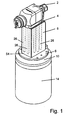
- Fig. 1 shows an automatic spray gun 2 for spray coating objects with liquid paint or paint.
- the spray gun 2 is attached via an intermediate plate 4 to an adapter 6, which has an adapter flange 8.
- the adapter flange 8 is fastened by means of screws (not shown) to a robot flange 10, which may be in one or more parts and is fastened by screws 12 to a tubular end portion of a robot arm 14.
- a plurality of tubes 20 extending through the robotic arm 14 is required.
- a new device for connecting the plurality of hoses 20 is provided at the end of the tubular robot arm 14 with holes 26 in the adapter 6.
- the adapter 6 is an intermediate body in a mechanical connection, which in the illustrated embodiment consists of the adapter 6 and the intermediate plate 4.
- adapter 6 and intermediate plate 4 only a single intermediate element or both intermediate plate 4 and adapter 6 are omitted and the spray gun 2 are attached directly to the robot flange 10, in which latter case a housing of the spray gun 2 itself serves as an intermediate body between the hoses 20 of the robot arm 14 and the internal lines of the spray gun 2.
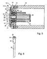
- the robot flange 10 is provided with a plurality of flanged holes 30, in each of which a hose connector socket 32 inserted, which is respectively mated with the hose end of the hoses 20 and each rests with a radially protruding bush collar 34 on the front flange 36.
- the robot flange 10 may be formed in several parts and, for example, have a one-piece or multi-part flange 10-1 and a flanged ring 10-1 attached and arranged centrally to him flange plate 10-2.
- the flange holes 30 are formed in the flange plate 10-2, and the front flange surface 36 against which the protruding sleeve collars 34 are each a forward facing bore shoulder of a bore extension of the flange holes 30.
- the protruding sleeve collars 34 of the hose connectors 32 are in the face bore extension the flange holes 30 are each arranged completely sunk.
- the flange plate 10 has on its forward facing end face a, preferably cylindrical, recess 38 with a forward facing Base surface 40.
- the socket collar 34 are recessed into the base 40, so that they do not protrude from the base forward, but end with her preferably in alignment.
- a perforated plate 42 is arranged in the recess 38, which is preferably aligned with the forwardly facing end face 44 of the flange plate 10-2 in the radial direction.
- the perforated plate 42 extends radially beyond the bushing collars 34 of all the hose connectors 32.
- a plurality of through holes 46 are formed, which communicate with at least some of the flange holes 30 and thus also with the hose channels of the tubes 20, and also with the adjacent ends the holes 26 in the adapter 6 are arranged axially in alignment.
- annular seal 48 and 50 is respectively arranged, which surrounds the respective through hole 46.
- the seals 48 on the rear side of the plate sealingly abut each other on a front end surface 52 of a hose connection socket 32 or are arranged in the disassembled state of the line connecting device such that they can be applied.
- the seals 50 on the front flange side are each sealingly against a rear end wall 54 of the adapter 6 (FIGS. Fig. 1 ), wherein each seal 50 each sealingly surrounds the bore end of one of the holes 26 formed in the adapter 6.
- the seals 48 and 50 are preferably inserted into annular recesses 49 and 51, respectively, of the perforated plate 42, from which they protrude somewhat axially from the perforated plate 42, at least in the non-assembled state of the line connecting device.
- the perforated plate 42 is fastened by means of screws 60 in threaded bores 62 of the flange plate 10-2.
- the flange plate 10-2 is fastened to the flange ring 10 by means of screws 66, for example.
- the tubes 20 may be withdrawn forwardly through the flanged holes 30, then provided with the hose connectors 32 at their ends, and then returned to the robot arm 14 with the flange connectors 32 inserted into the flanges 30.
Landscapes
- Engineering & Computer Science (AREA)
- General Engineering & Computer Science (AREA)
- Mechanical Engineering (AREA)
- Spray Control Apparatus (AREA)
- Quick-Acting Or Multi-Walled Pipe Joints (AREA)
- Details Or Accessories Of Spraying Plant Or Apparatus (AREA)
Abstract
Description
Die Erfindung betrifft eine Spritzpistolen-Leitungsverbindungsvorrichtung gemäß dem Oberbegriff von Anspruch 1.The invention relates to a spray gun line connecting device according to the preamble of claim 1.
Spritzpistolen dieser Art dienen zum Sprühbeschichten von Gegenständen mit flüssiger Farbe oder flüssigem Lack. Spritzpistolen dieser Art sind beispielsweise aus der
Eine Spritzpistolen-Leitungsverbindungsvorrichtung gemäß dem Oberbegriff von Anspruch 1 ist aus der
Durch die Erfindung soll die Aufgabe gelöst werden, die Leitungsverbindungsvorrichtung zwischen einem Roboterarm und mindestens einer vom Roboterarm getragenen Spritzpistole zu verbessern.By the invention, the problem to be solved is to improve the line connecting device between a robot arm and at least one carried by the robot arm spray gun.
Diese Aufgabe wird gemäß der Erfindung durch die Merkmale von Anspruch 1 gelöst.This object is achieved according to the invention by the features of claim 1.
Durch eine Lochplatte lassen sich gemäß der Erfindung folgende Vorteile erzielen: ein guter Schutz der Schlauchanschlussbuchsen vor mechanischen Beschädigungen und vor Schmutz; eine preiswerte und gute Abdichtung, vorzugsweise mittels O-Ringen, auf der Rückseite und auf der Vorderseite der Lochplatte für die Zuführung von flüssiger Farbe oder flüssigem Lack und von einem oder mehreren Luftströmen von dem Paket von Schläuchen im Roboterarm zu mindestens einer Spritzpistole, welche von dem Roboterarm getragen wird.By a perforated plate can be achieved according to the invention the following advantages: good protection of the hose connection sockets from mechanical damage and dirt; an inexpensive and good seal, preferably by means of O-rings, on the back and on the front of the perforated plate for the supply of liquid paint or liquid paint and one or more air streams from the package of tubes in the robot arm to at least one spray gun, which of the robot arm is worn.
Weitere Merkmale der Erfindung sind in den Unteransprüchen enthalten.Further features of the invention are contained in the subclaims.
Durch die erfindungsgemäße Unterbringung von Dichtungen in Vertiefungen, z.B. Ringnuten oder Bohrungsabsätzen, der Lochplatte wird auf einfache Weise eine exakte Positionierung der Dichtungen erzielt.By accommodating seals in recesses, e.g. Ring grooves or bore heels, the perforated plate is achieved in a simple manner an exact positioning of the seals.
Durch die erfindungsgemäße Befestigung der Lochplatte an einem Roboterflansch oder am Roboterarm ist sie gegen Verlust auch dann gesichert, wenn am Roboterarm keine Spritzpistole befestigt ist.The inventive attachment of the perforated plate on a robot flange or on the robot arm is secured against loss even if no spray gun is attached to the robot arm.
Eine Spritzpistole oder ein Zwischenkörper, mittels welch letzterem eine oder mehrere Spritzpistolen mit dem Roboterarm verbindbar sind, kann am Roboterarm, am Roboterflansch oder an der Lochplatte befestigt werden, je nach Zweckmäßigkeit in der praktischen Anwendung der Erfindung.A spray gun or an intermediate body, by means of which the latter one or more spray guns are connectable to the robot arm, may be attached to the robot arm, to the robot flange or to the perforated plate, as appropriate in the practice of the invention.
Gemäß einer besonderen Ausführungsform der Erfindung sind die Buchsenkragen von Schlauchanschlussbuchsen nicht wie beim Stand der Technik mit einem mehreckigen, zum Beispiel sechseckigen, Außenumfang versehen, sondern mit einem kreisrunden Außenumfang. Dadurch sind kleinere Abstände zwischen den Flanschlöchern und damit auch zwischen den Schläuchen möglich. Die kreisrunde Form der Buchsenkragen erleichtert den Einbau und den Ausbau der Schläuche, da die radial überstehenden Buchsenkragen in jeder beliebigen Drehrichtung positionierbar sind, ohne mit benachbarten Buchsenkragen zu kollidieren. Dadurch ist auch die Verwendung von größeren Maßtoleranzen möglich.According to a particular embodiment of the invention, the socket collars of hose connection sockets are not provided, as in the prior art, with a polygonal, for example hexagonal, outer circumference, but with a circular outer circumference. As a result, smaller distances between the flange holes and thus between the hoses are possible. The circular shape of the bush collar facilitates the installation and removal of the hoses, as the radially protruding bush collar can be positioned in any direction without colliding with adjacent socket collar. This also allows the use of larger dimensional tolerances.
Die Erfindung wird im Folgenden mit Bezug auf die beiliegenden Zeichnungen anhand von einer bevorzugten Ausführungsform als Beispiel beschrieben. In den Zeichnungen zeigen
- Fig. 1
- eine perspektivische Darstellung einer automatischen Spritzpistole, welche an einem Roboterarm befestigt ist,
- Fig. 2
- eine perspektivische Explosionsdarstellung des Endabschnittes des Roboterarmes mit einem sich aus ihm heraus erstreckenden Paket von Schläuchen und einer Lochplatte,
- Fig. 3
- eine perspektivische vordere Stirnansicht des Roboterarmes mit der daran befestigten Lochplatte, welche die in den Roboterarm zurückgeschobenen Schlauchenden zudeckt,
- Fig. 4
- eine vordere Stirnansicht des Roboterarmes von
Fig. 3 , - Fig. 5
- einen abgebrochenen Längsschnitt des Roboterarmes in der radialen Ebene V-V von
Fig. 4 , - Fig. 6
- einen Endabschnitt eines Schlauches von
Fig. 2 mit einer auf ihn aufgesteckten Schlauchanschlussbuchse, welche mit dem Schlauch verbunden ist, beispielsweise mit dem Schlauch verklemmt ist.
- Fig. 1
- a perspective view of an automatic spray gun, which is attached to a robot arm,
- Fig. 2
- an exploded perspective view of the end portion of the robot arm with an outwardly extending package of tubes and a perforated plate,
- Fig. 3
- a perspective front end view of the robot arm with the attached perforated plate, which covers the pushed back into the robot arm hose ends,
- Fig. 4
- a front end view of the robot arm of
Fig. 3 . - Fig. 5
- a broken longitudinal section of the robot arm in the radial plane VV of
Fig. 4 . - Fig. 6
- an end portion of a hose of
Fig. 2 with a plugged on him hose connection socket, which is connected to the hose, for example, clamped to the hose.
Gemäß der Erfindung ist eine neue Vorrichtung für die Verbindung der Vielzahl von Schläuchen 20 am Ende des rohrartigen Roboterarmes 14 mit Bohrungen 26 in dem Adapter 6 vorgesehen. Der Adapter 6 ist ein Zwischenkörper in einer mechanischen Verbindung, welcher bei der dargestellten Ausführungsform aus dem Adapter 6 und der Zwischenplatte 4 besteht. Gemäß einer anderen Ausführungsform könnte anstelle von Adapter 6 und Zwischenplatte 4 nur ein einziges Zwischenelement vorgesehen sein oder sowohl Zwischenplatte 4 als auch Adapter 6 weggelassen werden und die Spritzpistole 2 direkt an dem Roboterflansch 10 befestigt werden, in welch letzterem Falle ein Gehäuse der Spritzpistole 2 selbst als Zwischenkörper zwischen den Schläuchen 20 des Roboterarmes 14 und den internen Leitungen der Spritzpistole 2 dient.According to the invention, a new device for connecting the plurality of
Wie die
Die Flanschplatte 10 hat auf ihrer nach vorne zeigenden Stirnseite eine, vorzugsweise zylindrische, Vertiefung 38 mit einer nach vorne zeigenden Grundfläche 40. Die Buchsenkragen 34 sind in die Grundfläche 40 versenkt, so dass sie nicht aus der Grundfläche nach vorne hinausragen, sondern mit ihr vorzugsweise fluchtend enden.The
Gemäß der Erfindung ist in der Vertiefung 38 eine Lochplatte 42 angeordnet, welche mit der nach vorne zeigenden Stirnfläche 44 der Flanschplatte 10-2 in Radialrichtung vorzugsweise fluchtet.According to the invention, a
Die Lochplatte 42 erstreckt sich radial über die Buchsenkragen 34 von allen Schlauchanschlussbuchsen 32. In der Lochplatte 42 ist eine Vielzahl von Durchgangslöchern 46 gebildet, die mit mindestens einigen der Flanschlöcher 30 und damit auch mit den Schlauchkanälen der Schläuche 20, und auch mit den benachbarten Enden der Bohrungen 26 im Adapter 6 axial fluchtend angeordnet sind.The
An beiden Lochenden der Durchgangslöcher 46 der Lochplatte 42 ist jeweils eine ringförmige Dichtung 48 bzw. 50 angeordnet, welche das betreffende Durchgangsloch 46 umgibt.At both hole ends of the through
Die Dichtungen 48 auf der hinteren Plattenseite liegen jeweils dichtend an einer vorderen Stirnfläche 52 einer Schlauchanschlussbuchse 32 dichtend an oder sind im demontierten Zustand der Leitungsverbindungsvorrichtung derart angeordnet, dass sie anlegbar sind.The
Die Dichtungen 50 auf der vorderen Flanschseite liegen jeweils dichtend gegen eine hintere Stirnwand 54 des Adapters 6 (
Die Dichtungen 48 und 50 sind vorzugsweise in ringförmige Vertiefungen 49 bzw. 51 der Lochplatte 42 eingesetzt, aus welchen sie, zumindest im nicht-montierten Zustand der Leitungsverbindungsvorrichtung, aus der Lochplatte 42 etwas axial hervorragen.The
Die Lochplatte 42 ist mittels Schrauben 60 in Gewindebohrungen 62 der Flanschplatte 10-2 befestigt.The
Die Flanschplatte 10-2 ist beispielsweise mittels Schrauben 66 an dem Flanschring 10 befestigt.The flange plate 10-2 is fastened to the
Wie
Claims (3)
- Spray-gun line-connecting device for the connection of a multiplicity of pipe means (20) to the end of a tubular robot arm (14), through which the pipe means (20) extend, with bores (26) in an intermediate element (6, 4), which is arranged in a mechanical connection between the robot arm (14) and at least one automatic spray gun (2), the robot arm (14) having a robot flange (10) on the end, which flange is fastened to the robot arm and has a multiplicity of flange holes (30), wherein a perforated plate (42) is arranged between the robot flange (10) and the intermediate element (6, 4), which perforated plate extends transversely over pipe means connecting sockets (32) and has a multiplicity of through-holes (46), which are arranged in line with at least some of the flange holes (30); wherein at both ends of the through-holes (46) there is respectively arranged an annular seal (48, 50), which surrounds the through-hole (46) concerned; wherein the seals (48) on the rear plate side respectively lie or can be laid in a sealing manner against an end face of one of the pipe means connecting sockets (32); wherein the seals (50) on the front flange side respectively lie or can be laid against a rear end wall of the intermediate element (6, 4), in each case around one of a multiplicity of intermediate element bores (26) formed in the intermediate element (6, 4), which bores are arranged in line with at least some of the through-holes (46) of the perforated plate (42), characterized
in that the pipe means are tubes and in that the robot flange (10) has a cylindrical depression (38) in its forwardly pointing end face (44), in which depression the perforated plate (42) is arranged such that it is in line with the end face (44), and in that a respective tube connecting socket (32) is inserted in the multiplicity of flange holes (30), which tube connecting socket is respectively connected to the end of one of the tubes (20) and respectively lies with a radially protruding socket collar (34), against a front flange face (36), the socket collars (34) having a circular outer circumference. - Spray-gun line-connecting device according to Claim 1,
characterized
in that the annular seals (48, 50) of the perforated plate (42) are respectively positioned in a depression (49, 51) in the perforated plate (42). - Spray-gun line-connecting device according to either of the preceding claims,
characterized
in that the perforated plate (42) is fastened or can be fastened to the robot flange (10), preferably is or can be fastened in such a way that it can be released again.
Applications Claiming Priority (3)
| Application Number | Priority Date | Filing Date | Title |
|---|---|---|---|
| DE102007014216A DE102007014216A1 (en) | 2007-03-24 | 2007-03-24 | Airbrush power connection device |
| DE202007004372U DE202007004372U1 (en) | 2007-03-24 | 2007-03-24 | Airbrush pipe connection apparatus |
| PCT/EP2008/053179 WO2008116778A1 (en) | 2007-03-24 | 2008-03-17 | Spray gun line connection device |
Publications (2)
| Publication Number | Publication Date |
|---|---|
| EP2139608A1 EP2139608A1 (en) | 2010-01-06 |
| EP2139608B1 true EP2139608B1 (en) | 2011-06-15 |
Family
ID=40427879
Family Applications (1)
| Application Number | Title | Priority Date | Filing Date |
|---|---|---|---|
| EP08717914A Not-in-force EP2139608B1 (en) | 2007-03-24 | 2008-03-17 | Spray gun line connection device |
Country Status (6)
| Country | Link |
|---|---|
| US (1) | US8256694B2 (en) |
| EP (1) | EP2139608B1 (en) |
| JP (1) | JP5485867B2 (en) |
| CN (1) | CN101711187B (en) |
| DE (2) | DE102007014216A1 (en) |
| WO (1) | WO2008116778A1 (en) |
Families Citing this family (7)
| Publication number | Priority date | Publication date | Assignee | Title |
|---|---|---|---|---|
| DE102007053578A1 (en) | 2007-11-07 | 2009-05-14 | ITW Oberflächentechnik GmbH & Co. KG | Automatic spray gun for coating liquid and its combination with a robot |
| DE102012022535A1 (en) * | 2012-11-16 | 2014-05-22 | Eisenmann Ag | Applicator connection unit, application robot and equipment for coating objects |
| CN104797874B (en) * | 2012-11-21 | 2017-10-27 | 美国国民油井华高公司 | Sealing system |
| CN107303674B (en) * | 2016-04-19 | 2025-02-21 | 麦荷机器人(苏州)有限公司 | Robotic system |
| CN107631114B (en) * | 2017-09-14 | 2019-04-05 | 北京航天发射技术研究所 | A gas-liquid combined butt connector |
| ES2981258T3 (en) * | 2020-03-25 | 2024-10-08 | Basf Coatings Gmbh | Atomizer changing system for multi-axis hollow wrist coating robots |
| CN113478521B (en) * | 2021-07-14 | 2022-12-30 | 东莞科卓机器人有限公司 | Horizontal joint robot shared by gas circuit and circuit |
Citations (1)
| Publication number | Priority date | Publication date | Assignee | Title |
|---|---|---|---|---|
| EP1514610A1 (en) * | 2003-09-15 | 2005-03-16 | Illinois Tool Works Inc. | Split shroud for coating dispensing equipment |
Family Cites Families (13)
| Publication number | Priority date | Publication date | Assignee | Title |
|---|---|---|---|---|
| US5320283A (en) * | 1993-01-28 | 1994-06-14 | Nordson Corporation | Robot mounted twin headed adjustable powder coating system with spray pattern direction control |
| JPH1015442A (en) * | 1996-07-05 | 1998-01-20 | Anest Iwata Corp | Coating material feed flow path of automatic manifold shaped gun |
| DE29622839U1 (en) * | 1996-11-09 | 1997-06-19 | ITW Oberflächentechnik GmbH, 63128 Dietzenbach | Spray coating device |
| US5887800A (en) * | 1997-09-03 | 1999-03-30 | Fanuc Robotics North America, Inc. | Robot wrist and spray applicator |
| WO1999036182A1 (en) * | 1998-01-13 | 1999-07-22 | Abb K.K. | Rotary atomizing head type coating device |
| JP3263373B2 (en) * | 1998-12-18 | 2002-03-04 | エービービー株式会社 | Automatic coating equipment |
| DE29905689U1 (en) * | 1999-03-27 | 1999-07-29 | ITW Oberflächentechnik GmbH, 63128 Dietzenbach | Spray gun robot adapter |
| FR2797788B1 (en) * | 1999-08-30 | 2001-11-23 | Sames Sa | PRODUCT CHANGE METHOD AND STATION IN A COATING PRODUCT SPRAYING SYSTEM |
| ES2311011T3 (en) * | 2000-04-25 | 2009-02-01 | Abb K.K. | CARTRIDGE TYPE PAINT SYSTEM. |
| DE10142074A1 (en) * | 2001-08-29 | 2003-04-10 | Itw Oberflaechentechnik Gmbh | Spray coater |
| JP2004249149A (en) * | 2003-02-18 | 2004-09-09 | Fuji Photo Film Co Ltd | Attaching structure for spray pipe |
| DE202004007024U1 (en) | 2004-04-30 | 2004-07-01 | Nordson Corporation, Westlake | Application head, application nozzle arrangement, adapter plate and mounting plate |
| DE102004047923B4 (en) * | 2004-10-01 | 2008-02-28 | Krautzberger Gmbh | Fastening device for spray guns |
-
2007
- 2007-03-24 DE DE102007014216A patent/DE102007014216A1/en not_active Withdrawn
- 2007-03-24 DE DE202007004372U patent/DE202007004372U1/en not_active Expired - Lifetime
-
2008
- 2008-03-17 JP JP2010500207A patent/JP5485867B2/en not_active Expired - Fee Related
- 2008-03-17 EP EP08717914A patent/EP2139608B1/en not_active Not-in-force
- 2008-03-17 WO PCT/EP2008/053179 patent/WO2008116778A1/en not_active Ceased
- 2008-03-17 US US12/532,997 patent/US8256694B2/en active Active
- 2008-03-17 CN CN2008800094478A patent/CN101711187B/en not_active Expired - Fee Related
Patent Citations (1)
| Publication number | Priority date | Publication date | Assignee | Title |
|---|---|---|---|---|
| EP1514610A1 (en) * | 2003-09-15 | 2005-03-16 | Illinois Tool Works Inc. | Split shroud for coating dispensing equipment |
Also Published As
| Publication number | Publication date |
|---|---|
| DE202007004372U1 (en) | 2007-07-19 |
| JP2010521304A (en) | 2010-06-24 |
| DE102007014216A1 (en) | 2008-09-25 |
| US8256694B2 (en) | 2012-09-04 |
| EP2139608A1 (en) | 2010-01-06 |
| CN101711187A (en) | 2010-05-19 |
| US20100116914A1 (en) | 2010-05-13 |
| WO2008116778A1 (en) | 2008-10-02 |
| JP5485867B2 (en) | 2014-05-07 |
| CN101711187B (en) | 2013-07-31 |
Similar Documents
| Publication | Publication Date | Title |
|---|---|---|
| DE10317819B4 (en) | Distribution connection mechanism | |
| EP2207626A1 (en) | Connection of a spray head to a robot arm | |
| WO2008116778A1 (en) | Spray gun line connection device | |
| DE2701212C2 (en) | Plug-in coupling for multi-core pressure lines, in particular hydraulic high-pressure hose lines | |
| EP1835144A2 (en) | Connection for a tube-shaped air guide element to a turbo charger | |
| DE602005003582T2 (en) | AUTOMATED SPRAY GUNS WITH A SPRAY SYSTEM FIXED TO A SUPPLY BASE | |
| EP2620688A2 (en) | Connection unit for a multiple coupling and multiple coupling with such a connection unit | |
| DE69427980T2 (en) | FASTENING A PIPE TO THE VALVE OUTLET COMBINED WITH THE VALVE | |
| DE2913686B2 (en) | Plug-in coupling for multi-core hydraulic or pneumatic cables | |
| DE19914040B4 (en) | Spray gun robot adapter | |
| EP3243559B1 (en) | Filter assembly | |
| DE4219679C1 (en) | Valve arrangement | |
| DE102013003897B4 (en) | Nozzle carrier for the attachment of a Lackierdüse to a Lackzerstäubereinrichtung and Lackzerstäubereinrichtung with such a nozzle carrier | |
| DE3875344T2 (en) | BALL CLAMP QUICK COUPLING. | |
| DE8315893U1 (en) | FILTRATION UNIT WITH BUILT-IN VALVE | |
| EP0655558B1 (en) | Pneumatic valve device with at least two fixed together subassemblies | |
| EP3101318B1 (en) | Valve module | |
| DE4234262A1 (en) | Wall-mounted connector with self-locking connector part | |
| DE202019106638U1 (en) | Connection element for polygonal tubes | |
| EP2068006B1 (en) | Valve assembly comprising multiple stacked multi-way valve plates | |
| EP4559583A1 (en) | Fixing aid for components in a spray or spray system and spray or spray applicator for coating workpieces with fixing aid | |
| EP4559584A1 (en) | Quick-change coupling for a spray applicator for detachably connecting a spray head to a spray applicator holder and spray applicator with quick-change coupling | |
| DE2731819A1 (en) | Heating fluid distributor for central heating systems - has coloured plastics sleeves with lugs and sealing rings connected axially | |
| DE102024131773A1 (en) | Fluid supply arrangement | |
| EP1169597B1 (en) | Coupling device for the quick-release coupling of hose-like or tubular pipes to a connecting part |
Legal Events
| Date | Code | Title | Description |
|---|---|---|---|
| PUAI | Public reference made under article 153(3) epc to a published international application that has entered the european phase |
Free format text: ORIGINAL CODE: 0009012 |
|
| 17P | Request for examination filed |
Effective date: 20090916 |
|
| AK | Designated contracting states |
Kind code of ref document: A1 Designated state(s): AT BE BG CH CY CZ DE DK EE ES FI FR GB GR HR HU IE IS IT LI LT LU LV MC MT NL NO PL PT RO SE SI SK TR |
|
| 17Q | First examination report despatched |
Effective date: 20100113 |
|
| DAX | Request for extension of the european patent (deleted) | ||
| GRAP | Despatch of communication of intention to grant a patent |
Free format text: ORIGINAL CODE: EPIDOSNIGR1 |
|
| GRAS | Grant fee paid |
Free format text: ORIGINAL CODE: EPIDOSNIGR3 |
|
| GRAA | (expected) grant |
Free format text: ORIGINAL CODE: 0009210 |
|
| AK | Designated contracting states |
Kind code of ref document: B1 Designated state(s): AT BE BG CH CY CZ DE DK EE ES FI FR GB GR HR HU IE IS IT LI LT LU LV MC MT NL NO PL PT RO SE SI SK TR |
|
| REG | Reference to a national code |
Ref country code: GB Ref legal event code: FG4D Free format text: NOT ENGLISH Ref country code: CH Ref legal event code: EP |
|
| REG | Reference to a national code |
Ref country code: IE Ref legal event code: FG4D Free format text: LANGUAGE OF EP DOCUMENT: GERMAN |
|
| REG | Reference to a national code |
Ref country code: DE Ref legal event code: R096 Ref document number: 502008003873 Country of ref document: DE Effective date: 20110728 |
|
| REG | Reference to a national code |
Ref country code: NL Ref legal event code: VDEP Effective date: 20110615 |
|
| PG25 | Lapsed in a contracting state [announced via postgrant information from national office to epo] |
Ref country code: SE Free format text: LAPSE BECAUSE OF FAILURE TO SUBMIT A TRANSLATION OF THE DESCRIPTION OR TO PAY THE FEE WITHIN THE PRESCRIBED TIME-LIMIT Effective date: 20110615 Ref country code: NO Free format text: LAPSE BECAUSE OF FAILURE TO SUBMIT A TRANSLATION OF THE DESCRIPTION OR TO PAY THE FEE WITHIN THE PRESCRIBED TIME-LIMIT Effective date: 20110915 Ref country code: HR Free format text: LAPSE BECAUSE OF FAILURE TO SUBMIT A TRANSLATION OF THE DESCRIPTION OR TO PAY THE FEE WITHIN THE PRESCRIBED TIME-LIMIT Effective date: 20110615 Ref country code: LT Free format text: LAPSE BECAUSE OF FAILURE TO SUBMIT A TRANSLATION OF THE DESCRIPTION OR TO PAY THE FEE WITHIN THE PRESCRIBED TIME-LIMIT Effective date: 20110615 |
|
| REG | Reference to a national code |
Ref country code: ES Ref legal event code: FG2A Ref document number: 2367600 Country of ref document: ES Kind code of ref document: T3 Effective date: 20111104 |
|
| PG25 | Lapsed in a contracting state [announced via postgrant information from national office to epo] |
Ref country code: CY Free format text: LAPSE BECAUSE OF FAILURE TO SUBMIT A TRANSLATION OF THE DESCRIPTION OR TO PAY THE FEE WITHIN THE PRESCRIBED TIME-LIMIT Effective date: 20110615 Ref country code: FI Free format text: LAPSE BECAUSE OF FAILURE TO SUBMIT A TRANSLATION OF THE DESCRIPTION OR TO PAY THE FEE WITHIN THE PRESCRIBED TIME-LIMIT Effective date: 20110615 Ref country code: LV Free format text: LAPSE BECAUSE OF FAILURE TO SUBMIT A TRANSLATION OF THE DESCRIPTION OR TO PAY THE FEE WITHIN THE PRESCRIBED TIME-LIMIT Effective date: 20110615 Ref country code: GR Free format text: LAPSE BECAUSE OF FAILURE TO SUBMIT A TRANSLATION OF THE DESCRIPTION OR TO PAY THE FEE WITHIN THE PRESCRIBED TIME-LIMIT Effective date: 20110916 Ref country code: SI Free format text: LAPSE BECAUSE OF FAILURE TO SUBMIT A TRANSLATION OF THE DESCRIPTION OR TO PAY THE FEE WITHIN THE PRESCRIBED TIME-LIMIT Effective date: 20110615 |
|
| PG25 | Lapsed in a contracting state [announced via postgrant information from national office to epo] |
Ref country code: NL Free format text: LAPSE BECAUSE OF FAILURE TO SUBMIT A TRANSLATION OF THE DESCRIPTION OR TO PAY THE FEE WITHIN THE PRESCRIBED TIME-LIMIT Effective date: 20110615 |
|
| REG | Reference to a national code |
Ref country code: IE Ref legal event code: FD4D |
|
| PG25 | Lapsed in a contracting state [announced via postgrant information from national office to epo] |
Ref country code: CZ Free format text: LAPSE BECAUSE OF FAILURE TO SUBMIT A TRANSLATION OF THE DESCRIPTION OR TO PAY THE FEE WITHIN THE PRESCRIBED TIME-LIMIT Effective date: 20110615 Ref country code: IE Free format text: LAPSE BECAUSE OF FAILURE TO SUBMIT A TRANSLATION OF THE DESCRIPTION OR TO PAY THE FEE WITHIN THE PRESCRIBED TIME-LIMIT Effective date: 20110615 Ref country code: EE Free format text: LAPSE BECAUSE OF FAILURE TO SUBMIT A TRANSLATION OF THE DESCRIPTION OR TO PAY THE FEE WITHIN THE PRESCRIBED TIME-LIMIT Effective date: 20110615 Ref country code: IS Free format text: LAPSE BECAUSE OF FAILURE TO SUBMIT A TRANSLATION OF THE DESCRIPTION OR TO PAY THE FEE WITHIN THE PRESCRIBED TIME-LIMIT Effective date: 20111015 Ref country code: PT Free format text: LAPSE BECAUSE OF FAILURE TO SUBMIT A TRANSLATION OF THE DESCRIPTION OR TO PAY THE FEE WITHIN THE PRESCRIBED TIME-LIMIT Effective date: 20111017 |
|
| PG25 | Lapsed in a contracting state [announced via postgrant information from national office to epo] |
Ref country code: SK Free format text: LAPSE BECAUSE OF FAILURE TO SUBMIT A TRANSLATION OF THE DESCRIPTION OR TO PAY THE FEE WITHIN THE PRESCRIBED TIME-LIMIT Effective date: 20110615 Ref country code: RO Free format text: LAPSE BECAUSE OF FAILURE TO SUBMIT A TRANSLATION OF THE DESCRIPTION OR TO PAY THE FEE WITHIN THE PRESCRIBED TIME-LIMIT Effective date: 20110615 Ref country code: PL Free format text: LAPSE BECAUSE OF FAILURE TO SUBMIT A TRANSLATION OF THE DESCRIPTION OR TO PAY THE FEE WITHIN THE PRESCRIBED TIME-LIMIT Effective date: 20110615 |
|
| PLBE | No opposition filed within time limit |
Free format text: ORIGINAL CODE: 0009261 |
|
| STAA | Information on the status of an ep patent application or granted ep patent |
Free format text: STATUS: NO OPPOSITION FILED WITHIN TIME LIMIT |
|
| 26N | No opposition filed |
Effective date: 20120316 |
|
| PG25 | Lapsed in a contracting state [announced via postgrant information from national office to epo] |
Ref country code: DK Free format text: LAPSE BECAUSE OF FAILURE TO SUBMIT A TRANSLATION OF THE DESCRIPTION OR TO PAY THE FEE WITHIN THE PRESCRIBED TIME-LIMIT Effective date: 20110615 |
|
| REG | Reference to a national code |
Ref country code: DE Ref legal event code: R097 Ref document number: 502008003873 Country of ref document: DE Effective date: 20120316 |
|
| BERE | Be: lapsed |
Owner name: ITW OBERFLACHENTECHNIK G.M.B.H. Effective date: 20120331 |
|
| PG25 | Lapsed in a contracting state [announced via postgrant information from national office to epo] |
Ref country code: MC Free format text: LAPSE BECAUSE OF NON-PAYMENT OF DUE FEES Effective date: 20120331 |
|
| REG | Reference to a national code |
Ref country code: CH Ref legal event code: PL |
|
| GBPC | Gb: european patent ceased through non-payment of renewal fee |
Effective date: 20120317 |
|
| PG25 | Lapsed in a contracting state [announced via postgrant information from national office to epo] |
Ref country code: GB Free format text: LAPSE BECAUSE OF NON-PAYMENT OF DUE FEES Effective date: 20120317 Ref country code: BE Free format text: LAPSE BECAUSE OF NON-PAYMENT OF DUE FEES Effective date: 20120331 Ref country code: CH Free format text: LAPSE BECAUSE OF NON-PAYMENT OF DUE FEES Effective date: 20120331 Ref country code: LI Free format text: LAPSE BECAUSE OF NON-PAYMENT OF DUE FEES Effective date: 20120331 |
|
| PG25 | Lapsed in a contracting state [announced via postgrant information from national office to epo] |
Ref country code: BG Free format text: LAPSE BECAUSE OF FAILURE TO SUBMIT A TRANSLATION OF THE DESCRIPTION OR TO PAY THE FEE WITHIN THE PRESCRIBED TIME-LIMIT Effective date: 20110915 |
|
| PG25 | Lapsed in a contracting state [announced via postgrant information from national office to epo] |
Ref country code: MT Free format text: LAPSE BECAUSE OF FAILURE TO SUBMIT A TRANSLATION OF THE DESCRIPTION OR TO PAY THE FEE WITHIN THE PRESCRIBED TIME-LIMIT Effective date: 20110615 |
|
| REG | Reference to a national code |
Ref country code: DE Ref legal event code: R081 Ref document number: 502008003873 Country of ref document: DE Owner name: FINISHING BRANDS GERMANY GMBH, DE Free format text: FORMER OWNER: ITW OBERFLAECHENTECHNIK GMBH, 63128 DIETZENBACH, DE Effective date: 20140306 |
|
| REG | Reference to a national code |
Ref country code: FR Ref legal event code: CD Owner name: FINISHING BRANDS GERMANY GMBH Effective date: 20140326 |
|
| PG25 | Lapsed in a contracting state [announced via postgrant information from national office to epo] |
Ref country code: TR Free format text: LAPSE BECAUSE OF FAILURE TO SUBMIT A TRANSLATION OF THE DESCRIPTION OR TO PAY THE FEE WITHIN THE PRESCRIBED TIME-LIMIT Effective date: 20110615 |
|
| REG | Reference to a national code |
Ref country code: AT Ref legal event code: MM01 Ref document number: 512725 Country of ref document: AT Kind code of ref document: T Effective date: 20130317 |
|
| PG25 | Lapsed in a contracting state [announced via postgrant information from national office to epo] |
Ref country code: LU Free format text: LAPSE BECAUSE OF NON-PAYMENT OF DUE FEES Effective date: 20120317 |
|
| PG25 | Lapsed in a contracting state [announced via postgrant information from national office to epo] |
Ref country code: HU Free format text: LAPSE BECAUSE OF FAILURE TO SUBMIT A TRANSLATION OF THE DESCRIPTION OR TO PAY THE FEE WITHIN THE PRESCRIBED TIME-LIMIT Effective date: 20080317 |
|
| PG25 | Lapsed in a contracting state [announced via postgrant information from national office to epo] |
Ref country code: AT Free format text: LAPSE BECAUSE OF NON-PAYMENT OF DUE FEES Effective date: 20130317 |
|
| REG | Reference to a national code |
Ref country code: ES Ref legal event code: PC2A Owner name: FINISHING BRANDS GERMANY GMBH Effective date: 20150811 |
|
| REG | Reference to a national code |
Ref country code: FR Ref legal event code: PLFP Year of fee payment: 9 |
|
| REG | Reference to a national code |
Ref country code: FR Ref legal event code: PLFP Year of fee payment: 10 |
|
| REG | Reference to a national code |
Ref country code: DE Ref legal event code: R079 Ref document number: 502008003873 Country of ref document: DE Free format text: PREVIOUS MAIN CLASS: B05B0015060000 Ipc: B05B0015600000 |
|
| REG | Reference to a national code |
Ref country code: FR Ref legal event code: PLFP Year of fee payment: 11 |
|
| PGFP | Annual fee paid to national office [announced via postgrant information from national office to epo] |
Ref country code: ES Payment date: 20190319 Year of fee payment: 12 Ref country code: IT Payment date: 20190322 Year of fee payment: 12 |
|
| PGFP | Annual fee paid to national office [announced via postgrant information from national office to epo] |
Ref country code: ES Payment date: 20190401 Year of fee payment: 12 |
|
| PGFP | Annual fee paid to national office [announced via postgrant information from national office to epo] |
Ref country code: DE Payment date: 20200327 Year of fee payment: 13 |
|
| PG25 | Lapsed in a contracting state [announced via postgrant information from national office to epo] |
Ref country code: FR Free format text: LAPSE BECAUSE OF NON-PAYMENT OF DUE FEES Effective date: 20200331 |
|
| REG | Reference to a national code |
Ref country code: ES Ref legal event code: FD2A Effective date: 20210802 |
|
| REG | Reference to a national code |
Ref country code: DE Ref legal event code: R119 Ref document number: 502008003873 Country of ref document: DE |
|
| PG25 | Lapsed in a contracting state [announced via postgrant information from national office to epo] |
Ref country code: IT Free format text: LAPSE BECAUSE OF NON-PAYMENT OF DUE FEES Effective date: 20200317 |
|
| PG25 | Lapsed in a contracting state [announced via postgrant information from national office to epo] |
Ref country code: ES Free format text: LAPSE BECAUSE OF NON-PAYMENT OF DUE FEES Effective date: 20200318 |
|
| PG25 | Lapsed in a contracting state [announced via postgrant information from national office to epo] |
Ref country code: DE Free format text: LAPSE BECAUSE OF NON-PAYMENT OF DUE FEES Effective date: 20211001 |