EP2139608B1 - Dispositif de raccordement de conduite de pistolet pulvérisateur - Google Patents
Dispositif de raccordement de conduite de pistolet pulvérisateur Download PDFInfo
- Publication number
- EP2139608B1 EP2139608B1 EP08717914A EP08717914A EP2139608B1 EP 2139608 B1 EP2139608 B1 EP 2139608B1 EP 08717914 A EP08717914 A EP 08717914A EP 08717914 A EP08717914 A EP 08717914A EP 2139608 B1 EP2139608 B1 EP 2139608B1
- Authority
- EP
- European Patent Office
- Prior art keywords
- flange
- perforated plate
- holes
- robot
- robot arm
- Prior art date
- Legal status (The legal status is an assumption and is not a legal conclusion. Google has not performed a legal analysis and makes no representation as to the accuracy of the status listed.)
- Not-in-force
Links
Images

Classifications
-
- F—MECHANICAL ENGINEERING; LIGHTING; HEATING; WEAPONS; BLASTING
- F16—ENGINEERING ELEMENTS AND UNITS; GENERAL MEASURES FOR PRODUCING AND MAINTAINING EFFECTIVE FUNCTIONING OF MACHINES OR INSTALLATIONS; THERMAL INSULATION IN GENERAL
- F16L—PIPES; JOINTS OR FITTINGS FOR PIPES; SUPPORTS FOR PIPES, CABLES OR PROTECTIVE TUBING; MEANS FOR THERMAL INSULATION IN GENERAL
- F16L39/00—Joints or fittings for double-walled or multi-channel pipes or pipe assemblies
- F16L39/02—Joints or fittings for double-walled or multi-channel pipes or pipe assemblies for hoses
-
- B—PERFORMING OPERATIONS; TRANSPORTING
- B05—SPRAYING OR ATOMISING IN GENERAL; APPLYING FLUENT MATERIALS TO SURFACES, IN GENERAL
- B05B—SPRAYING APPARATUS; ATOMISING APPARATUS; NOZZLES
- B05B15/00—Details of spraying plant or spraying apparatus not otherwise provided for; Accessories
- B05B15/60—Arrangements for mounting, supporting or holding spraying apparatus
- B05B15/65—Mounting arrangements for fluid connection of the spraying apparatus or its outlets to flow conduits
-
- B—PERFORMING OPERATIONS; TRANSPORTING
- B05—SPRAYING OR ATOMISING IN GENERAL; APPLYING FLUENT MATERIALS TO SURFACES, IN GENERAL
- B05B—SPRAYING APPARATUS; ATOMISING APPARATUS; NOZZLES
- B05B13/00—Machines or plants for applying liquids or other fluent materials to surfaces of objects or other work by spraying, not covered by groups B05B1/00 - B05B11/00
- B05B13/02—Means for supporting work; Arrangement or mounting of spray heads; Adaptation or arrangement of means for feeding work
- B05B13/04—Means for supporting work; Arrangement or mounting of spray heads; Adaptation or arrangement of means for feeding work the spray heads being moved during spraying operation
- B05B13/0431—Means for supporting work; Arrangement or mounting of spray heads; Adaptation or arrangement of means for feeding work the spray heads being moved during spraying operation with spray heads moved by robots or articulated arms, e.g. for applying liquid or other fluent material to three-dimensional [3D] surfaces
-
- B—PERFORMING OPERATIONS; TRANSPORTING
- B05—SPRAYING OR ATOMISING IN GENERAL; APPLYING FLUENT MATERIALS TO SURFACES, IN GENERAL
- B05B—SPRAYING APPARATUS; ATOMISING APPARATUS; NOZZLES
- B05B15/00—Details of spraying plant or spraying apparatus not otherwise provided for; Accessories
- B05B15/50—Arrangements for cleaning; Arrangements for preventing deposits, drying-out or blockage; Arrangements for detecting improper discharge caused by the presence of foreign matter
-
- B—PERFORMING OPERATIONS; TRANSPORTING
- B05—SPRAYING OR ATOMISING IN GENERAL; APPLYING FLUENT MATERIALS TO SURFACES, IN GENERAL
- B05B—SPRAYING APPARATUS; ATOMISING APPARATUS; NOZZLES
- B05B15/00—Details of spraying plant or spraying apparatus not otherwise provided for; Accessories
- B05B15/60—Arrangements for mounting, supporting or holding spraying apparatus
- B05B15/65—Mounting arrangements for fluid connection of the spraying apparatus or its outlets to flow conduits
- B05B15/658—Mounting arrangements for fluid connection of the spraying apparatus or its outlets to flow conduits the spraying apparatus or its outlet axis being perpendicular to the flow conduit
-
- B—PERFORMING OPERATIONS; TRANSPORTING
- B05—SPRAYING OR ATOMISING IN GENERAL; APPLYING FLUENT MATERIALS TO SURFACES, IN GENERAL
- B05B—SPRAYING APPARATUS; ATOMISING APPARATUS; NOZZLES
- B05B7/00—Spraying apparatus for discharge of liquids or other fluent materials from two or more sources, e.g. of liquid and air, of powder and gas
- B05B7/02—Spray pistols; Apparatus for discharge
- B05B7/08—Spray pistols; Apparatus for discharge with separate outlet orifices, e.g. to form parallel jets, i.e. the axis of the jets being parallel, to form intersecting jets, i.e. the axis of the jets converging but not necessarily intersecting at a point
- B05B7/0807—Spray pistols; Apparatus for discharge with separate outlet orifices, e.g. to form parallel jets, i.e. the axis of the jets being parallel, to form intersecting jets, i.e. the axis of the jets converging but not necessarily intersecting at a point to form intersecting jets
- B05B7/0815—Spray pistols; Apparatus for discharge with separate outlet orifices, e.g. to form parallel jets, i.e. the axis of the jets being parallel, to form intersecting jets, i.e. the axis of the jets converging but not necessarily intersecting at a point to form intersecting jets with at least one gas jet intersecting a jet constituted by a liquid or a mixture containing a liquid for controlling the shape of the latter
Definitions
- the invention relates to a spray gun line connecting device according to the preamble of claim 1.
- Spray guns of this type are used for spray coating objects with liquid paint or liquid paint.
- Spray guns of this type are for example from the EP 1 287 901 B1 known.
- a spray gun line connecting device according to the preamble of claim 1 is known from DE 199 14 040 A1 known.
- the problem to be solved is to improve the line connecting device between a robot arm and at least one carried by the robot arm spray gun.
- a perforated plate By a perforated plate can be achieved according to the invention the following advantages: good protection of the hose connection sockets from mechanical damage and dirt; an inexpensive and good seal, preferably by means of O-rings, on the back and on the front of the perforated plate for the supply of liquid paint or liquid paint and one or more air streams from the package of tubes in the robot arm to at least one spray gun, which of the robot arm is worn.
- the perforated plate is achieved in a simple manner an exact positioning of the seals.
- a spray gun or an intermediate body, by means of which the latter one or more spray guns are connectable to the robot arm, may be attached to the robot arm, to the robot flange or to the perforated plate, as appropriate in the practice of the invention.
- the socket collars of hose connection sockets are not provided, as in the prior art, with a polygonal, for example hexagonal, outer circumference, but with a circular outer circumference.
- a polygonal, for example hexagonal, outer circumference for example hexagonal, outer circumference
- a circular outer circumference for example hexagonal, outer circumference
- the circular shape of the bush collar facilitates the installation and removal of the hoses, as the radially protruding bush collar can be positioned in any direction without colliding with adjacent socket collar. This also allows the use of larger dimensional tolerances.
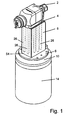
- Fig. 1 shows an automatic spray gun 2 for spray coating objects with liquid paint or paint.
- the spray gun 2 is attached via an intermediate plate 4 to an adapter 6, which has an adapter flange 8.
- the adapter flange 8 is fastened by means of screws (not shown) to a robot flange 10, which may be in one or more parts and is fastened by screws 12 to a tubular end portion of a robot arm 14.
- a plurality of tubes 20 extending through the robotic arm 14 is required.
- a new device for connecting the plurality of hoses 20 is provided at the end of the tubular robot arm 14 with holes 26 in the adapter 6.
- the adapter 6 is an intermediate body in a mechanical connection, which in the illustrated embodiment consists of the adapter 6 and the intermediate plate 4.
- adapter 6 and intermediate plate 4 only a single intermediate element or both intermediate plate 4 and adapter 6 are omitted and the spray gun 2 are attached directly to the robot flange 10, in which latter case a housing of the spray gun 2 itself serves as an intermediate body between the hoses 20 of the robot arm 14 and the internal lines of the spray gun 2.
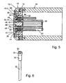
- the robot flange 10 is provided with a plurality of flanged holes 30, in each of which a hose connector socket 32 inserted, which is respectively mated with the hose end of the hoses 20 and each rests with a radially protruding bush collar 34 on the front flange 36.
- the robot flange 10 may be formed in several parts and, for example, have a one-piece or multi-part flange 10-1 and a flanged ring 10-1 attached and arranged centrally to him flange plate 10-2.
- the flange holes 30 are formed in the flange plate 10-2, and the front flange surface 36 against which the protruding sleeve collars 34 are each a forward facing bore shoulder of a bore extension of the flange holes 30.
- the protruding sleeve collars 34 of the hose connectors 32 are in the face bore extension the flange holes 30 are each arranged completely sunk.
- the flange plate 10 has on its forward facing end face a, preferably cylindrical, recess 38 with a forward facing Base surface 40.
- the socket collar 34 are recessed into the base 40, so that they do not protrude from the base forward, but end with her preferably in alignment.
- a perforated plate 42 is arranged in the recess 38, which is preferably aligned with the forwardly facing end face 44 of the flange plate 10-2 in the radial direction.
- the perforated plate 42 extends radially beyond the bushing collars 34 of all the hose connectors 32.
- a plurality of through holes 46 are formed, which communicate with at least some of the flange holes 30 and thus also with the hose channels of the tubes 20, and also with the adjacent ends the holes 26 in the adapter 6 are arranged axially in alignment.
- annular seal 48 and 50 is respectively arranged, which surrounds the respective through hole 46.
- the seals 48 on the rear side of the plate sealingly abut each other on a front end surface 52 of a hose connection socket 32 or are arranged in the disassembled state of the line connecting device such that they can be applied.
- the seals 50 on the front flange side are each sealingly against a rear end wall 54 of the adapter 6 (FIGS. Fig. 1 ), wherein each seal 50 each sealingly surrounds the bore end of one of the holes 26 formed in the adapter 6.
- the seals 48 and 50 are preferably inserted into annular recesses 49 and 51, respectively, of the perforated plate 42, from which they protrude somewhat axially from the perforated plate 42, at least in the non-assembled state of the line connecting device.
- the perforated plate 42 is fastened by means of screws 60 in threaded bores 62 of the flange plate 10-2.
- the flange plate 10-2 is fastened to the flange ring 10 by means of screws 66, for example.
- the tubes 20 may be withdrawn forwardly through the flanged holes 30, then provided with the hose connectors 32 at their ends, and then returned to the robot arm 14 with the flange connectors 32 inserted into the flanges 30.
Landscapes
- Engineering & Computer Science (AREA)
- General Engineering & Computer Science (AREA)
- Mechanical Engineering (AREA)
- Spray Control Apparatus (AREA)
- Quick-Acting Or Multi-Walled Pipe Joints (AREA)
- Details Or Accessories Of Spraying Plant Or Apparatus (AREA)
Abstract
Claims (3)
- Dispositif de raccordement de conduite de pistolet pulvérisateur pour le raccordement d'une pluralité de moyens de conduite (20) à l'extrémité d'un bras de robot de type tubulaire (14), à travers lequel s'étendent les moyens de conduite (20), comprenant des alésages (26) dans un corps intermédiaire (6, 4) qui est disposé dans un raccord mécanique entre le bras de robot (14) et au moins un pistolet pulvérisateur automatique (2), le bras de robot (14) présentant à l'extrémité une bride de robot (10) qui est fixée sur lui et qui présente une pluralité de trous de bride (30), une plaque perforée (42) étant disposée entre la bride de robot (10) et le corps intermédiaire (6, 4), laquelle s'étend transversalement par-dessus des douilles de raccordement des moyens de conduite (32) et présente une pluralité de trous traversants (46) qui sont disposés en affleurement avec au moins certains des trous de bride (30) ; un joint d'étanchéité de forme annulaire (48, 50) étant à chaque fois disposé aux deux extrémités des trous traversants (46), lequel entoure le trou traversant concerné (46) ; les joints d'étanchéité (48) s'appliquant ou pouvant être appliqués hermétiquement sur le côté arrière de la plaque à chaque fois contre une face frontale de l'une des douilles de raccordement des moyens de conduite (32) ; les joints d'étanchéité (50) sur le côté de bride avant s'appliquant ou pouvant être appliqués à chaque fois contre une paroi frontale arrière du corps intermédiaire (6, 4), à chaque fois autour d'un parmi une pluralité d'alésages de corps intermédiaire (26) formés dans le corps intermédiaire (6, 4), ces derniers étant disposés en affleurement avec au moins certains des trous traversants (46) de la plaque perforée (42),
caractérisé en ce que
les moyens de conduite sont des tuyaux flexibles et en ce que la bride de robot (10) présente, dans sa face frontale (44) tournée vers l'avant, un renfoncement cylindrique (38) dans lequel est disposée la plaque perforée (42) de telle sorte qu'elle soit en affleurement avec la face frontale (44), et en ce que dans la pluralité des trous de bride (30) est à chaque fois enfichée une douille de raccordement de tuyau flexible (32) qui est à chaque fois connectée à l'extrémité de tuyau flexible de l'un des tuyaux flexibles (20) et qui s'applique à chaque fois avec un col de douille saillant radialement (34) contre une face de bride avant (36), les cols de douille (34) ayant une périphérie extérieure ronde circulaire. - Dispositif de raccordement de conduite de pistolet pulvérisateur selon la revendication 1,
caractérisé en ce que
les joints d'étanchéité de forme annulaire (48, 50) de la plaque perforée (42) sont à chaque fois positionnés dans un renfoncement (49, 51) de la plaque perforée (42). - Dispositif de raccordement de conduite de pistolet pulvérisateur selon l'une quelconque des revendications précédentes,
caractérisé en ce que
la plaque perforée (42) est fixée ou peut être fixée sur la bride de robot (10), de préférence est fixée ou peut être fixée de manière desserrable.
Applications Claiming Priority (3)
| Application Number | Priority Date | Filing Date | Title |
|---|---|---|---|
| DE102007014216A DE102007014216A1 (de) | 2007-03-24 | 2007-03-24 | Spritzpistolen-Leistungsverbindungsvorrichtung |
| DE202007004372U DE202007004372U1 (de) | 2007-03-24 | 2007-03-24 | Spritzpistolen-Leitungsverbindungsvorrichtung |
| PCT/EP2008/053179 WO2008116778A1 (fr) | 2007-03-24 | 2008-03-17 | Dispositif de raccordement de conduite de pistolet pulvérisateur |
Publications (2)
| Publication Number | Publication Date |
|---|---|
| EP2139608A1 EP2139608A1 (fr) | 2010-01-06 |
| EP2139608B1 true EP2139608B1 (fr) | 2011-06-15 |
Family
ID=40427879
Family Applications (1)
| Application Number | Title | Priority Date | Filing Date |
|---|---|---|---|
| EP08717914A Not-in-force EP2139608B1 (fr) | 2007-03-24 | 2008-03-17 | Dispositif de raccordement de conduite de pistolet pulvérisateur |
Country Status (6)
| Country | Link |
|---|---|
| US (1) | US8256694B2 (fr) |
| EP (1) | EP2139608B1 (fr) |
| JP (1) | JP5485867B2 (fr) |
| CN (1) | CN101711187B (fr) |
| DE (2) | DE102007014216A1 (fr) |
| WO (1) | WO2008116778A1 (fr) |
Families Citing this family (7)
| Publication number | Priority date | Publication date | Assignee | Title |
|---|---|---|---|---|
| DE102007053578A1 (de) | 2007-11-07 | 2009-05-14 | ITW Oberflächentechnik GmbH & Co. KG | Automatischer Spritzapparat für Beschichtungsflüssigkeit und seine Kombination mit einem Roboter |
| DE102012022535A1 (de) * | 2012-11-16 | 2014-05-22 | Eisenmann Ag | Applikator-Anschlusseinheit, Applikationsroboter und Anlage zum Beschichten von Gegenständen |
| PL2923134T3 (pl) * | 2012-11-21 | 2018-06-29 | National Oilwell Varco, L.P. | Układ uszczelniający |
| CN107303674B (zh) * | 2016-04-19 | 2025-02-21 | 麦荷机器人(苏州)有限公司 | 机器人系统 |
| CN107631114B (zh) * | 2017-09-14 | 2019-04-05 | 北京航天发射技术研究所 | 一种气液组合对接连接器 |
| WO2021191383A1 (fr) * | 2020-03-25 | 2021-09-30 | Basf Coatings Gmbh | Système de changement d'atomiseur pour robots de revêtement à poignet creux à axes multiples |
| CN113478521B (zh) * | 2021-07-14 | 2022-12-30 | 东莞科卓机器人有限公司 | 一种气路电路共用的水平关节机器人 |
Citations (1)
| Publication number | Priority date | Publication date | Assignee | Title |
|---|---|---|---|---|
| EP1514610A1 (fr) * | 2003-09-15 | 2005-03-16 | Illinois Tool Works Inc. | Enveloppe en deux parties pour un appareil de revêtement |
Family Cites Families (13)
| Publication number | Priority date | Publication date | Assignee | Title |
|---|---|---|---|---|
| US5320283A (en) * | 1993-01-28 | 1994-06-14 | Nordson Corporation | Robot mounted twin headed adjustable powder coating system with spray pattern direction control |
| JPH1015442A (ja) * | 1996-07-05 | 1998-01-20 | Anest Iwata Corp | マニホールド形自動ガンの塗料供給流路 |
| DE29622839U1 (de) * | 1996-11-09 | 1997-06-19 | ITW Oberflächentechnik GmbH, 63128 Dietzenbach | Sprühbeschichtungseinrichtung |
| US5887800A (en) * | 1997-09-03 | 1999-03-30 | Fanuc Robotics North America, Inc. | Robot wrist and spray applicator |
| US6164561A (en) * | 1998-01-13 | 2000-12-26 | Abb K.K. | Rotary atomizing head type coating device |
| JP3263373B2 (ja) * | 1998-12-18 | 2002-03-04 | エービービー株式会社 | 自動塗装装置 |
| DE19914040B4 (de) * | 1999-03-27 | 2004-04-15 | ITW Oberflächentechnik GmbH & Co. KG | Sprühpistolen-Roboter-Adapter |
| FR2797788B1 (fr) * | 1999-08-30 | 2001-11-23 | Sames Sa | Procede et station de changement de produit dans une installation de projection de produit de revetement |
| EP1277520B1 (fr) * | 2000-04-25 | 2008-08-20 | Abb K.K. | Systeme de peinture du type cartouche |
| DE10142074A1 (de) * | 2001-08-29 | 2003-04-10 | Itw Oberflaechentechnik Gmbh | Spritzbeschichtungseinrichtung |
| JP2004249149A (ja) * | 2003-02-18 | 2004-09-09 | Fuji Photo Film Co Ltd | スプレー管の取付構造 |
| DE202004007024U1 (de) * | 2004-04-30 | 2004-07-01 | Nordson Corporation, Westlake | Auftragskopf, Auftragsdüsenanordnung, Adapterplatte sowie Montageplatte |
| DE102004047923B4 (de) * | 2004-10-01 | 2008-02-28 | Krautzberger Gmbh | Befestigungsvorrichtung für Spritzapparate |
-
2007
- 2007-03-24 DE DE102007014216A patent/DE102007014216A1/de not_active Withdrawn
- 2007-03-24 DE DE202007004372U patent/DE202007004372U1/de not_active Expired - Lifetime
-
2008
- 2008-03-17 EP EP08717914A patent/EP2139608B1/fr not_active Not-in-force
- 2008-03-17 WO PCT/EP2008/053179 patent/WO2008116778A1/fr not_active Ceased
- 2008-03-17 JP JP2010500207A patent/JP5485867B2/ja not_active Expired - Fee Related
- 2008-03-17 CN CN2008800094478A patent/CN101711187B/zh not_active Expired - Fee Related
- 2008-03-17 US US12/532,997 patent/US8256694B2/en active Active
Patent Citations (1)
| Publication number | Priority date | Publication date | Assignee | Title |
|---|---|---|---|---|
| EP1514610A1 (fr) * | 2003-09-15 | 2005-03-16 | Illinois Tool Works Inc. | Enveloppe en deux parties pour un appareil de revêtement |
Also Published As
| Publication number | Publication date |
|---|---|
| JP2010521304A (ja) | 2010-06-24 |
| DE102007014216A1 (de) | 2008-09-25 |
| US20100116914A1 (en) | 2010-05-13 |
| EP2139608A1 (fr) | 2010-01-06 |
| CN101711187B (zh) | 2013-07-31 |
| WO2008116778A1 (fr) | 2008-10-02 |
| DE202007004372U1 (de) | 2007-06-14 |
| US8256694B2 (en) | 2012-09-04 |
| JP5485867B2 (ja) | 2014-05-07 |
| CN101711187A (zh) | 2010-05-19 |
Similar Documents
| Publication | Publication Date | Title |
|---|---|---|
| EP2139608B1 (fr) | Dispositif de raccordement de conduite de pistolet pulvérisateur | |
| DE10317819B4 (de) | Verteilerverbindungsmechanismus | |
| DE2701212C2 (de) | Steckkupplung für mehradrige Druckleitungen, insbesondere hydraulische Hochdruck-Schlauchleitungen | |
| EP1835144A2 (fr) | Branchement pour élément d'arrivée d'air en forme de tuyau sur une turbocompresseur | |
| EP2207626A1 (fr) | Connexion d'une tête de pulvérisation à un bras de robot | |
| DE602005003582T2 (de) | Mit einem auf einer versorgungsbasis befestigten spritzsystem versehene automatisierte spritzpistole | |
| DE69427980T2 (de) | Befestigung eines rohres am auslass eines ventils kombiniert mit dem ventil | |
| CH653426A5 (de) | Verbindungsvorrichtung fuer sanitaerinstallationen mit flexibler, beiderends anschlussmittel aufweisender verbindungsleitung. | |
| DE2913686B2 (de) | Steckkupplung für mehradrige hydraulische oder pneumatische Kabel | |
| DE4219679C1 (de) | Ventilanordnung | |
| DE102013003897B4 (de) | Düsenträger für die Befestigung einer Lackierdüse an einer Lackzerstäubereinrichtung und Lackzerstäubereinrichtung mit einem solchen Düsenträger | |
| DE3875344T2 (de) | Kugelrast-schnellkupplung. | |
| EP3243559B1 (fr) | Système de filtre | |
| DE8315893U1 (de) | Filtrationseinheit mit eingebautem ventil | |
| EP0655558B1 (fr) | Soupape pneumatique avec au moins deux modules fixés l'un à l'autre | |
| EP3101318B1 (fr) | Module de vanne | |
| DE4234262A1 (de) | In einer Wand befestigter Verbinder mit selbsthaltendem Verbinderteil | |
| DE202019106638U1 (de) | Verbindungselement für Mehrkantrohre | |
| EP2068006B1 (fr) | Unité de soupape dotée de plusieurs soupapes multivoies juxtaposées | |
| EP4559583A1 (fr) | Auxiliaire de fixation pour composants dans un système de pulvérisation ou de pulvérisation et applicateur de pulvérisation ou de pulvérisation pour le revêtement de pièces à l'aide de fixation | |
| EP4559584A1 (fr) | Raccord à changement rapide pour un applicateur de pulvérisation pour la connexion amovible d'une tête de pulvérisation à un support d'applicateur de pulvérisation et applicateur de pulvérisation à couplage rapide | |
| DE2731819A1 (de) | Heizmittelverteiler | |
| EP1169597B1 (fr) | Dispositif d'accouplement pour le raccord rapide de conduites en forme de tuyaux flexibles ou de tubes comportant un corps de raccordement | |
| EP1253367B1 (fr) | nppareil pour la connexion d'un conduit pneumatique | |
| DE7722091U1 (de) | Heizmittelverteiler |
Legal Events
| Date | Code | Title | Description |
|---|---|---|---|
| PUAI | Public reference made under article 153(3) epc to a published international application that has entered the european phase |
Free format text: ORIGINAL CODE: 0009012 |
|
| 17P | Request for examination filed |
Effective date: 20090916 |
|
| AK | Designated contracting states |
Kind code of ref document: A1 Designated state(s): AT BE BG CH CY CZ DE DK EE ES FI FR GB GR HR HU IE IS IT LI LT LU LV MC MT NL NO PL PT RO SE SI SK TR |
|
| 17Q | First examination report despatched |
Effective date: 20100113 |
|
| DAX | Request for extension of the european patent (deleted) | ||
| GRAP | Despatch of communication of intention to grant a patent |
Free format text: ORIGINAL CODE: EPIDOSNIGR1 |
|
| GRAS | Grant fee paid |
Free format text: ORIGINAL CODE: EPIDOSNIGR3 |
|
| GRAA | (expected) grant |
Free format text: ORIGINAL CODE: 0009210 |
|
| AK | Designated contracting states |
Kind code of ref document: B1 Designated state(s): AT BE BG CH CY CZ DE DK EE ES FI FR GB GR HR HU IE IS IT LI LT LU LV MC MT NL NO PL PT RO SE SI SK TR |
|
| REG | Reference to a national code |
Ref country code: GB Ref legal event code: FG4D Free format text: NOT ENGLISH Ref country code: CH Ref legal event code: EP |
|
| REG | Reference to a national code |
Ref country code: IE Ref legal event code: FG4D Free format text: LANGUAGE OF EP DOCUMENT: GERMAN |
|
| REG | Reference to a national code |
Ref country code: DE Ref legal event code: R096 Ref document number: 502008003873 Country of ref document: DE Effective date: 20110728 |
|
| REG | Reference to a national code |
Ref country code: NL Ref legal event code: VDEP Effective date: 20110615 |
|
| PG25 | Lapsed in a contracting state [announced via postgrant information from national office to epo] |
Ref country code: SE Free format text: LAPSE BECAUSE OF FAILURE TO SUBMIT A TRANSLATION OF THE DESCRIPTION OR TO PAY THE FEE WITHIN THE PRESCRIBED TIME-LIMIT Effective date: 20110615 Ref country code: NO Free format text: LAPSE BECAUSE OF FAILURE TO SUBMIT A TRANSLATION OF THE DESCRIPTION OR TO PAY THE FEE WITHIN THE PRESCRIBED TIME-LIMIT Effective date: 20110915 Ref country code: HR Free format text: LAPSE BECAUSE OF FAILURE TO SUBMIT A TRANSLATION OF THE DESCRIPTION OR TO PAY THE FEE WITHIN THE PRESCRIBED TIME-LIMIT Effective date: 20110615 Ref country code: LT Free format text: LAPSE BECAUSE OF FAILURE TO SUBMIT A TRANSLATION OF THE DESCRIPTION OR TO PAY THE FEE WITHIN THE PRESCRIBED TIME-LIMIT Effective date: 20110615 |
|
| REG | Reference to a national code |
Ref country code: ES Ref legal event code: FG2A Ref document number: 2367600 Country of ref document: ES Kind code of ref document: T3 Effective date: 20111104 |
|
| PG25 | Lapsed in a contracting state [announced via postgrant information from national office to epo] |
Ref country code: CY Free format text: LAPSE BECAUSE OF FAILURE TO SUBMIT A TRANSLATION OF THE DESCRIPTION OR TO PAY THE FEE WITHIN THE PRESCRIBED TIME-LIMIT Effective date: 20110615 Ref country code: FI Free format text: LAPSE BECAUSE OF FAILURE TO SUBMIT A TRANSLATION OF THE DESCRIPTION OR TO PAY THE FEE WITHIN THE PRESCRIBED TIME-LIMIT Effective date: 20110615 Ref country code: LV Free format text: LAPSE BECAUSE OF FAILURE TO SUBMIT A TRANSLATION OF THE DESCRIPTION OR TO PAY THE FEE WITHIN THE PRESCRIBED TIME-LIMIT Effective date: 20110615 Ref country code: GR Free format text: LAPSE BECAUSE OF FAILURE TO SUBMIT A TRANSLATION OF THE DESCRIPTION OR TO PAY THE FEE WITHIN THE PRESCRIBED TIME-LIMIT Effective date: 20110916 Ref country code: SI Free format text: LAPSE BECAUSE OF FAILURE TO SUBMIT A TRANSLATION OF THE DESCRIPTION OR TO PAY THE FEE WITHIN THE PRESCRIBED TIME-LIMIT Effective date: 20110615 |
|
| PG25 | Lapsed in a contracting state [announced via postgrant information from national office to epo] |
Ref country code: NL Free format text: LAPSE BECAUSE OF FAILURE TO SUBMIT A TRANSLATION OF THE DESCRIPTION OR TO PAY THE FEE WITHIN THE PRESCRIBED TIME-LIMIT Effective date: 20110615 |
|
| REG | Reference to a national code |
Ref country code: IE Ref legal event code: FD4D |
|
| PG25 | Lapsed in a contracting state [announced via postgrant information from national office to epo] |
Ref country code: CZ Free format text: LAPSE BECAUSE OF FAILURE TO SUBMIT A TRANSLATION OF THE DESCRIPTION OR TO PAY THE FEE WITHIN THE PRESCRIBED TIME-LIMIT Effective date: 20110615 Ref country code: IE Free format text: LAPSE BECAUSE OF FAILURE TO SUBMIT A TRANSLATION OF THE DESCRIPTION OR TO PAY THE FEE WITHIN THE PRESCRIBED TIME-LIMIT Effective date: 20110615 Ref country code: EE Free format text: LAPSE BECAUSE OF FAILURE TO SUBMIT A TRANSLATION OF THE DESCRIPTION OR TO PAY THE FEE WITHIN THE PRESCRIBED TIME-LIMIT Effective date: 20110615 Ref country code: IS Free format text: LAPSE BECAUSE OF FAILURE TO SUBMIT A TRANSLATION OF THE DESCRIPTION OR TO PAY THE FEE WITHIN THE PRESCRIBED TIME-LIMIT Effective date: 20111015 Ref country code: PT Free format text: LAPSE BECAUSE OF FAILURE TO SUBMIT A TRANSLATION OF THE DESCRIPTION OR TO PAY THE FEE WITHIN THE PRESCRIBED TIME-LIMIT Effective date: 20111017 |
|
| PG25 | Lapsed in a contracting state [announced via postgrant information from national office to epo] |
Ref country code: SK Free format text: LAPSE BECAUSE OF FAILURE TO SUBMIT A TRANSLATION OF THE DESCRIPTION OR TO PAY THE FEE WITHIN THE PRESCRIBED TIME-LIMIT Effective date: 20110615 Ref country code: RO Free format text: LAPSE BECAUSE OF FAILURE TO SUBMIT A TRANSLATION OF THE DESCRIPTION OR TO PAY THE FEE WITHIN THE PRESCRIBED TIME-LIMIT Effective date: 20110615 Ref country code: PL Free format text: LAPSE BECAUSE OF FAILURE TO SUBMIT A TRANSLATION OF THE DESCRIPTION OR TO PAY THE FEE WITHIN THE PRESCRIBED TIME-LIMIT Effective date: 20110615 |
|
| PLBE | No opposition filed within time limit |
Free format text: ORIGINAL CODE: 0009261 |
|
| STAA | Information on the status of an ep patent application or granted ep patent |
Free format text: STATUS: NO OPPOSITION FILED WITHIN TIME LIMIT |
|
| 26N | No opposition filed |
Effective date: 20120316 |
|
| PG25 | Lapsed in a contracting state [announced via postgrant information from national office to epo] |
Ref country code: DK Free format text: LAPSE BECAUSE OF FAILURE TO SUBMIT A TRANSLATION OF THE DESCRIPTION OR TO PAY THE FEE WITHIN THE PRESCRIBED TIME-LIMIT Effective date: 20110615 |
|
| REG | Reference to a national code |
Ref country code: DE Ref legal event code: R097 Ref document number: 502008003873 Country of ref document: DE Effective date: 20120316 |
|
| BERE | Be: lapsed |
Owner name: ITW OBERFLACHENTECHNIK G.M.B.H. Effective date: 20120331 |
|
| PG25 | Lapsed in a contracting state [announced via postgrant information from national office to epo] |
Ref country code: MC Free format text: LAPSE BECAUSE OF NON-PAYMENT OF DUE FEES Effective date: 20120331 |
|
| REG | Reference to a national code |
Ref country code: CH Ref legal event code: PL |
|
| GBPC | Gb: european patent ceased through non-payment of renewal fee |
Effective date: 20120317 |
|
| PG25 | Lapsed in a contracting state [announced via postgrant information from national office to epo] |
Ref country code: GB Free format text: LAPSE BECAUSE OF NON-PAYMENT OF DUE FEES Effective date: 20120317 Ref country code: BE Free format text: LAPSE BECAUSE OF NON-PAYMENT OF DUE FEES Effective date: 20120331 Ref country code: CH Free format text: LAPSE BECAUSE OF NON-PAYMENT OF DUE FEES Effective date: 20120331 Ref country code: LI Free format text: LAPSE BECAUSE OF NON-PAYMENT OF DUE FEES Effective date: 20120331 |
|
| PG25 | Lapsed in a contracting state [announced via postgrant information from national office to epo] |
Ref country code: BG Free format text: LAPSE BECAUSE OF FAILURE TO SUBMIT A TRANSLATION OF THE DESCRIPTION OR TO PAY THE FEE WITHIN THE PRESCRIBED TIME-LIMIT Effective date: 20110915 |
|
| PG25 | Lapsed in a contracting state [announced via postgrant information from national office to epo] |
Ref country code: MT Free format text: LAPSE BECAUSE OF FAILURE TO SUBMIT A TRANSLATION OF THE DESCRIPTION OR TO PAY THE FEE WITHIN THE PRESCRIBED TIME-LIMIT Effective date: 20110615 |
|
| REG | Reference to a national code |
Ref country code: DE Ref legal event code: R081 Ref document number: 502008003873 Country of ref document: DE Owner name: FINISHING BRANDS GERMANY GMBH, DE Free format text: FORMER OWNER: ITW OBERFLAECHENTECHNIK GMBH, 63128 DIETZENBACH, DE Effective date: 20140306 |
|
| REG | Reference to a national code |
Ref country code: FR Ref legal event code: CD Owner name: FINISHING BRANDS GERMANY GMBH Effective date: 20140326 |
|
| PG25 | Lapsed in a contracting state [announced via postgrant information from national office to epo] |
Ref country code: TR Free format text: LAPSE BECAUSE OF FAILURE TO SUBMIT A TRANSLATION OF THE DESCRIPTION OR TO PAY THE FEE WITHIN THE PRESCRIBED TIME-LIMIT Effective date: 20110615 |
|
| REG | Reference to a national code |
Ref country code: AT Ref legal event code: MM01 Ref document number: 512725 Country of ref document: AT Kind code of ref document: T Effective date: 20130317 |
|
| PG25 | Lapsed in a contracting state [announced via postgrant information from national office to epo] |
Ref country code: LU Free format text: LAPSE BECAUSE OF NON-PAYMENT OF DUE FEES Effective date: 20120317 |
|
| PG25 | Lapsed in a contracting state [announced via postgrant information from national office to epo] |
Ref country code: HU Free format text: LAPSE BECAUSE OF FAILURE TO SUBMIT A TRANSLATION OF THE DESCRIPTION OR TO PAY THE FEE WITHIN THE PRESCRIBED TIME-LIMIT Effective date: 20080317 |
|
| PG25 | Lapsed in a contracting state [announced via postgrant information from national office to epo] |
Ref country code: AT Free format text: LAPSE BECAUSE OF NON-PAYMENT OF DUE FEES Effective date: 20130317 |
|
| REG | Reference to a national code |
Ref country code: ES Ref legal event code: PC2A Owner name: FINISHING BRANDS GERMANY GMBH Effective date: 20150811 |
|
| REG | Reference to a national code |
Ref country code: FR Ref legal event code: PLFP Year of fee payment: 9 |
|
| REG | Reference to a national code |
Ref country code: FR Ref legal event code: PLFP Year of fee payment: 10 |
|
| REG | Reference to a national code |
Ref country code: DE Ref legal event code: R079 Ref document number: 502008003873 Country of ref document: DE Free format text: PREVIOUS MAIN CLASS: B05B0015060000 Ipc: B05B0015600000 |
|
| REG | Reference to a national code |
Ref country code: FR Ref legal event code: PLFP Year of fee payment: 11 |
|
| PGFP | Annual fee paid to national office [announced via postgrant information from national office to epo] |
Ref country code: ES Payment date: 20190319 Year of fee payment: 12 Ref country code: IT Payment date: 20190322 Year of fee payment: 12 |
|
| PGFP | Annual fee paid to national office [announced via postgrant information from national office to epo] |
Ref country code: ES Payment date: 20190401 Year of fee payment: 12 |
|
| PGFP | Annual fee paid to national office [announced via postgrant information from national office to epo] |
Ref country code: DE Payment date: 20200327 Year of fee payment: 13 |
|
| PG25 | Lapsed in a contracting state [announced via postgrant information from national office to epo] |
Ref country code: FR Free format text: LAPSE BECAUSE OF NON-PAYMENT OF DUE FEES Effective date: 20200331 |
|
| REG | Reference to a national code |
Ref country code: ES Ref legal event code: FD2A Effective date: 20210802 |
|
| REG | Reference to a national code |
Ref country code: DE Ref legal event code: R119 Ref document number: 502008003873 Country of ref document: DE |
|
| PG25 | Lapsed in a contracting state [announced via postgrant information from national office to epo] |
Ref country code: IT Free format text: LAPSE BECAUSE OF NON-PAYMENT OF DUE FEES Effective date: 20200317 |
|
| PG25 | Lapsed in a contracting state [announced via postgrant information from national office to epo] |
Ref country code: ES Free format text: LAPSE BECAUSE OF NON-PAYMENT OF DUE FEES Effective date: 20200318 |
|
| PG25 | Lapsed in a contracting state [announced via postgrant information from national office to epo] |
Ref country code: DE Free format text: LAPSE BECAUSE OF NON-PAYMENT OF DUE FEES Effective date: 20211001 |