EP1514610A1 - Split shroud for coating dispensing equipment - Google Patents
Split shroud for coating dispensing equipment Download PDFInfo
- Publication number
- EP1514610A1 EP1514610A1 EP04019914A EP04019914A EP1514610A1 EP 1514610 A1 EP1514610 A1 EP 1514610A1 EP 04019914 A EP04019914 A EP 04019914A EP 04019914 A EP04019914 A EP 04019914A EP 1514610 A1 EP1514610 A1 EP 1514610A1
- Authority
- EP
- European Patent Office
- Prior art keywords
- shroud
- portions
- feature
- dispenser
- forward end
- Prior art date
- Legal status (The legal status is an assumption and is not a legal conclusion. Google has not performed a legal analysis and makes no representation as to the accuracy of the status listed.)
- Granted
Links
Images


Classifications
-
- B—PERFORMING OPERATIONS; TRANSPORTING
- B05—SPRAYING OR ATOMISING IN GENERAL; APPLYING FLUENT MATERIALS TO SURFACES, IN GENERAL
- B05B—SPRAYING APPARATUS; ATOMISING APPARATUS; NOZZLES
- B05B9/00—Spraying apparatus for discharge of liquids or other fluent material, without essentially mixing with gas or vapour
- B05B9/01—Spray pistols, discharge devices
-
- B—PERFORMING OPERATIONS; TRANSPORTING
- B05—SPRAYING OR ATOMISING IN GENERAL; APPLYING FLUENT MATERIALS TO SURFACES, IN GENERAL
- B05B—SPRAYING APPARATUS; ATOMISING APPARATUS; NOZZLES
- B05B7/00—Spraying apparatus for discharge of liquids or other fluent materials from two or more sources, e.g. of liquid and air, of powder and gas
- B05B7/14—Spraying apparatus for discharge of liquids or other fluent materials from two or more sources, e.g. of liquid and air, of powder and gas designed for spraying particulate materials
- B05B7/1481—Spray pistols or apparatus for discharging particulate material
- B05B7/1486—Spray pistols or apparatus for discharging particulate material for spraying particulate material in dry state
-
- B—PERFORMING OPERATIONS; TRANSPORTING
- B05—SPRAYING OR ATOMISING IN GENERAL; APPLYING FLUENT MATERIALS TO SURFACES, IN GENERAL
- B05B—SPRAYING APPARATUS; ATOMISING APPARATUS; NOZZLES
- B05B15/00—Details of spraying plant or spraying apparatus not otherwise provided for; Accessories
- B05B15/60—Arrangements for mounting, supporting or holding spraying apparatus
- B05B15/65—Mounting arrangements for fluid connection of the spraying apparatus or its outlets to flow conduits
-
- B—PERFORMING OPERATIONS; TRANSPORTING
- B05—SPRAYING OR ATOMISING IN GENERAL; APPLYING FLUENT MATERIALS TO SURFACES, IN GENERAL
- B05B—SPRAYING APPARATUS; ATOMISING APPARATUS; NOZZLES
- B05B5/00—Electrostatic spraying apparatus; Spraying apparatus with means for charging the spray electrically; Apparatus for spraying liquids or other fluent materials by other electric means
- B05B5/025—Discharge apparatus, e.g. electrostatic spray guns
- B05B5/03—Discharge apparatus, e.g. electrostatic spray guns characterised by the use of gas, e.g. electrostatically assisted pneumatic spraying
- B05B5/032—Discharge apparatus, e.g. electrostatic spray guns characterised by the use of gas, e.g. electrostatically assisted pneumatic spraying for spraying particulate materials
-
- B—PERFORMING OPERATIONS; TRANSPORTING
- B05—SPRAYING OR ATOMISING IN GENERAL; APPLYING FLUENT MATERIALS TO SURFACES, IN GENERAL
- B05B—SPRAYING APPARATUS; ATOMISING APPARATUS; NOZZLES
- B05B7/00—Spraying apparatus for discharge of liquids or other fluent materials from two or more sources, e.g. of liquid and air, of powder and gas
- B05B7/14—Spraying apparatus for discharge of liquids or other fluent materials from two or more sources, e.g. of liquid and air, of powder and gas designed for spraying particulate materials
- B05B7/1404—Arrangements for supplying particulate material
- B05B7/1477—Arrangements for supplying particulate material means for supplying to several spray apparatus
-
- B—PERFORMING OPERATIONS; TRANSPORTING
- B05—SPRAYING OR ATOMISING IN GENERAL; APPLYING FLUENT MATERIALS TO SURFACES, IN GENERAL
- B05B—SPRAYING APPARATUS; ATOMISING APPARATUS; NOZZLES
- B05B13/00—Machines or plants for applying liquids or other fluent materials to surfaces of objects or other work by spraying, not covered by groups B05B1/00 - B05B11/00
- B05B13/02—Means for supporting work; Arrangement or mounting of spray heads; Adaptation or arrangement of means for feeding work
- B05B13/04—Means for supporting work; Arrangement or mounting of spray heads; Adaptation or arrangement of means for feeding work the spray heads being moved during spraying operation
- B05B13/0431—Means for supporting work; Arrangement or mounting of spray heads; Adaptation or arrangement of means for feeding work the spray heads being moved during spraying operation with spray heads moved by robots or articulated arms, e.g. for applying liquid or other fluent material to 3D-surfaces
-
- B—PERFORMING OPERATIONS; TRANSPORTING
- B05—SPRAYING OR ATOMISING IN GENERAL; APPLYING FLUENT MATERIALS TO SURFACES, IN GENERAL
- B05B—SPRAYING APPARATUS; ATOMISING APPARATUS; NOZZLES
- B05B7/00—Spraying apparatus for discharge of liquids or other fluent materials from two or more sources, e.g. of liquid and air, of powder and gas
- B05B7/14—Spraying apparatus for discharge of liquids or other fluent materials from two or more sources, e.g. of liquid and air, of powder and gas designed for spraying particulate materials
- B05B7/1404—Arrangements for supplying particulate material
- B05B7/144—Arrangements for supplying particulate material the means for supplying particulate material comprising moving mechanical means
Definitions
- This invention relates to dispensers for dispensing coating materials such as liquid coating materials (hereinafter sometimes “paint”) or pulverulent coating material (hereinafter sometimes “coating powder” or “powder”) suspended in a gas stream, for example, a stream of air, from, for example, a fluidized powder bed. It is disclosed in the context of a dispenser (hereinafter sometimes a "gun”) for dispensing coating powder. However, it is believed to have utility in other applications as well.
- Patents 2,759,763; 2,955,565; 3,102,062; 3,233,655; 3,578,997; 3,589,607; 3,610,528; 3,684,174; 4,066,041; 4,171,100; 4,214,708; 4,215,818; 4,323,197; 4,350,304; 4,402,991; 4,422,577; Re.
- a dispenser includes an opening through which coating material is dispensed, a coupling for coupling the opening to a source of coating material to be dispensed, and a shroud for enclosing at least a portion of the dispenser.
- the shroud includes two portions which engage each other at first and second joints which extend generally longitudinally of the shroud.
- the shroud comprises a somewhat right cylindrical shroud
- the shroud comprises a somewhat right circular cylindrical shroud, and each of the two portions is consequently part right circular cylindrical.
- the shroud includes a longitudinal axis.
- a first one of the portions subtends an arc measured about the axis of somewhat more than 180°, and a second one of the portions subtends an arc about the axis of somewhat less than 180°.
- the first one of the portions subtends an arc measured about the axis of about 200°
- the second one of the portions subtends an arc measured about the axis of about 160°.
- the shroud portions are constructed from resilient, electrically non-conductive materials. Further illustratively according to this aspect, the shroud portions are constructed from acetal resin.
- the shroud portions include inner sidewalls including grooves which extend generally longitudinally therealong.
- a first of the shroud portions includes a lateral edge including a first feature
- a second of the shroud portions includes a lateral edge including a second feature which is complementary to the first feature
- the first feature comprises a somewhat V-bottomed groove
- the second feature comprises a somewhat V-shaped edge
- the first shroud portion includes two lateral edges. Each lateral edge of the first shroud portion includes a first feature.
- the second shroud portion includes two lateral edges. Each lateral edge of the second shroud portion includes a second feature which is complementary to the first feature.
- Each first feature comprises a somewhat V-bottomed groove.
- Each second feature comprises a somewhat V-shaped edge.
- the apparatus includes a gasket material interposed between the first and second features.
- the dispenser includes a forward end adjacent the opening.
- the forward end includes a feature for cooperating with a feature provided on a forward end of a first one of the shroud portions to facilitate engagement of the forward end of the first one of the shroud portions with the forward end of the dispenser.
- the forward end also includes a feature for cooperating with a feature provided on a forward end of a second one of the shroud portions to facilitate engagement of the forward end of the second one of the shroud portions with the forward end of the dispenser.
- the feature on the forward end of one of the dispenser and the shroud portions comprises a groove extending substantially continuously around a perimeter of the forward end of said one of the dispenser and the shroud portions, and the feature provided on the forward end of the other of the dispenser and the shroud portions includes a lip for engaging the groove.
- the dispenser includes a rearward end including a feature for cooperating with a feature provided on a rearward end of a first one of the shroud portions to facilitate engagement of the rearward end of the first one of the shroud portions with the rearward end of the dispenser.
- the rearward end of the dispenser also includes a feature for cooperating with a feature provided on a rearward end of a second one of the shroud portions to facilitate engagement of the rearward end of the second one of the shroud portions with the rearward end of the dispenser.
- the feature on a rearward end of the dispenser includes a ring including at least one tab
- the feature provided on a rearward end of a first one of the shroud portions includes a flange provided with at least one passageway permitting passage of the at least one tab therethrough during assembly of the shroud to the dispensing device.
- the dispenser includes a forward end adjacent the opening.
- the forward end includes a feature for cooperating with a feature provided on a forward end of a first one of the shroud portions to facilitate engagement of the forward end of the first one of the shroud portions with the forward end of the dispenser.
- the forward end of the dispenser also includes a feature for cooperating with a feature provided on a forward end of a second one of the shroud portions to facilitate engagement of the forward end of the second one of the shroud portions with the forward end of the dispenser.
- the feature provided on a rearward end of a first one of the shroud portions includes a ramp surface provided on the flange for cooperating with the at least one tab to urge the feature provided on a forward end of the first one of the shroud portions into engagement with the forward end of the dispenser.
- the source of coating material to be dispensed comprises a source of pulverulent coating material suspended in a gas or mixture of gases.
- electrically conductive and electrically non-insulative refer to a broad range of conductivities electrically more conductive than materials described as “electrically non-conductive” and “electrically insulative.”
- Terms such as “electrically semiconductive” refer to a broad range of conductivities between electrically conductive and electrically non-conductive. Terms such as “front,” “back,” “up,” “down,” and the like, are used only to describe an illustrative embodiment, and are not intended as limiting.
- Coating material particles are typically quite small. Sizes in the range of 5 ⁇ m-50 ⁇ m are not uncommon. As a result, coating material particles are typically highly penetrating, that is, capable of entering through small openings into, for example, equipment used to dispense them and accumulating there. As a consequence, it is desirable to design coating material dispensing equipment with a view toward being able to clean it without too much difficulty.
- cleaning of the powder coating equipment is conducted at intervals. Such cleaning may involve, for example, wiping down of the equipment to dislodge any accumulated powder.
- coating material dispensing equipment needs to be designed with a view toward conducting other types of maintenance, routine and otherwise, on the equipment.
- Maintenance sometimes involves disassembly of covers, or shrouds, which enclose components of the coating material dispensing system, for example, to reduce the exposure of such components to dispensed coating material.
- Covering of such components has the potential to reduce the amount and complexity of the cleaning which must be conducted on the dispensing equipment. Consequently, a consideration in the design of such shrouds is the ability of the shrouds to protect covered components against the ingress of coating material into the covered components, while at the same time facilitating the removal of the shrouds so that covered components can be serviced as necessary.
- Fig. 1 illustrates a powder gun 10 of the general type of, for example, an RPG-2 dual head robot powder gun model 78772 available from ITW GEMA Automotive Systems, ITW Automotive Finishing Group, 320 Phillips Ave, Toledo, Ohio 43612.
- Gun 10 includes two side-by-side nozzles 12, only one of which is illustrated. Each nozzle 12 is coupled through a respective powder delivery tube 14 to a respective inside-the-gun 10 powder hose barbed fitting 16 mounted in a passageway provided therefor in a robot powder gun rear plate 18 (also see Figs. 2-7).
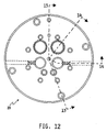
- Robot powder gun rear plate 18 is coupled by a threaded robot plate retaining ring 19 (see also Figs. 8-9) to a robot powder gun adapter plate 20 (see also Figs. 10-14).
- Each of plates 18, 20 includes mating passageways for the various services with which the gun 10 is provided.
- Such services for electrostatically aided liquid and powder coating guns include, for example, conductors for low- and/or high-magnitude electrical potential, coating material supplies, such as, for example, air entrained powder supplies, compressed gas, for example, air, and so on.
- Powder flows from a powder source 32 forward through powder delivery tube 14 to nozzle 12.
- Powder source 32 may be of any of a number of known types such as, for example, a fluidized bed of the general type illustrated and described in U. S. Patent 5,768,800.
- a powder supply hose 46 extends from powder source 32 through a robot arm (not shown) to the end of which robot powder gun adapter plate 20 is mounted.
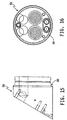
- a proximal end 47 of powder delivery tube 14 is coupled through a forward manifold 50 (see also Figs. 15-16) to the nozzles 12 mounted on manifold 50.
- Powder delivery tube 14 and other gun 10 components are housed between manifold 50 and the robot powder gun rear plate 18.
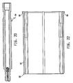
- the forward manifold 50 is supported from the rear plate 18 by a number, illustratively two, of support posts 52 (see also Figs. 17-19), 54 (see also Fig. 20) which include appropriate fastening means, such as threaded lugs and threaded holes, to facilitate attachment to rear plate 18 and manifold 50.
- Support posts 52, 54 may also include (a) cavity(ies), illustrated in post 54, for housing (a) resistor(s) for coupling between (a) corona ring(s) surrounding nozzles 12 and, for example, a reference potential, such as ground.
- An illustratively somewhat right circular cylindrical shroud 60 surrounds and encloses portions of such powder dispensing equipment, connections 14 and the like.
- the shroud 60 includes two portions 62 (see also Figs. 21, 22 and 27), 64 (see also Figs. 23, 24 and 27), which are sometimes referred to hereinafter as a larger portion 62 and a smaller portion 64.
- Each of the portions 62, 64 is part right circular cylindrical.
- the larger portion 62 subtends an arc measured about an axis 66 of the cylinder 60, of somewhat more than 180°, for example, 200°, while the smaller portion 64 subtends an arc about axis 66, of somewhat less than! 180°, for example, 160°.
- Shroud portions 62, 64 are illustratively constructed from electrically non-conductive materials which are flexible.
- An illustrative material includes white Acetron GP acetal resin. This flexibility enables components 62, 64 to be snapped over gun 10 components housed within the shroud 60 during assembly and disassembly. Grooves may be provided in the inner sidewalls of shroud portions 62, 64 to enhance flexibility. Additional features may be provided on the inner sidewalls of shroud portions 62, 64, for example, to facilitate assembly and disassembly of gun 10 components, to provide clearance between gun 10 components and shroud portions 62, 64, and so on.
- a first of the portions illustratively, the smaller portion 64, is provided with a feature 70, for example, a somewhat V-bottomed groove, along each of its lateral edges 72.
- the second of the portions illustratively, the larger portion 62, is provided with complementary feature 74, illustratively a somewhat V-shaped edge, along each of its lateral edges 76 to cooperate with respective ones of the somewhat V-bottomed grooves 70 along respective lateral edges 72 of the first portion 64.
- One or the other or both of features 70, 74 can be furnished with, for example, gasket material 78, such as, for example, O-ring material, to promote sealing of portions 62, 64 together to impede the penetration of dispensed coating material into the interior 79 of shroud 60.
- gasket material 78 such as, for example, O-ring material
- Forward manifold 50 includes a perimetrally extending, rearwardly facing feature 80, such as a groove or relief for cooperating with complementary forward features 82, illustratively lips, of larger shroud portion 62 and smaller shroud portion 64.
- each shroud portion 62, 64 includes a flange 90 which extends perimetrally partway around its rearward extent.
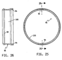
- Flanges 90 are interrupted at intervals by passageways 92 which permit the passage of respective tabs 94 of a shroud retainer ring 96 (see also Figs. 25-26).
- the interior of shroud retainer ring 96 is sized to receive in a sliding, sealing orientation the assembled shroud components 62, 64.
- a sealing O-ring 97 may be accommodated in a groove 98 provided therefor around the interior 100 of shroud retainer ring 96.
- the rearwardly facing side 102 of each flange 90 adjacent each passageway 92 is bevelled as illustrated at 104.
- the bevel 104 promotes entry of the finger 94 that projects through that respective passageway 92 during assembly of the shroud 60 onto gun 10 into the space between robot powder gun rear plate 18 and the flange 90 to urge features 80, 82 into sealing engagement.
Abstract
Description
- This invention relates to dispensers for dispensing coating materials such as liquid coating materials (hereinafter sometimes "paint") or pulverulent coating material (hereinafter sometimes "coating powder" or "powder") suspended in a gas stream, for example, a stream of air, from, for example, a fluidized powder bed. It is disclosed in the context of a dispenser (hereinafter sometimes a "gun") for dispensing coating powder. However, it is believed to have utility in other applications as well.
- Systems for dispensing coating materials are known. There are, for example, the systems illustrated and described in U. S. Patents: 3,536,514; 3,575,344; 3,698,636; 3,843,054; 3,913,523; 3,964,683; 4,037,561; 4,039,145; 4,114,564; 4,135,667; 4,169,560; 4,216,915; 4,360,155; 4,381,079; 4,447,008; 4,450,785; Re. 31,867; 4,520,754; 4,580,727; 4,598,870; 4,685,620; 4,788,933; 4,798,340; 4,802,625; 4,825,807; 4,921,172; 5,353,995; 5,358,182; 5,433,387; 5,720,436; 5,853,126; and, 6,328,224. There are also the devices illustrated and described in U. S. Patents: 2,759,763; 2,955,565; 3,102,062; 3,233,655; 3,578,997; 3,589,607; 3,610,528; 3,684,174; 4,066,041; 4,171,100; 4,214,708; 4,215,818; 4,323,197; 4,350,304; 4,402,991; 4,422,577; Re. 31,590; 4,505,430; 4,518,119; 4,726,521; 4,779,805; 4,785,995; 4,879,137; 4,890,190; and, 4,896,384; British Patent Specification 1,209,653; Japanese published patent applications: 62-140,660; 1-315,361; 3-169,361; 3-221,166; 60-151,554; 60-94,166; 63-116,776; 58-124,560; and 331,823 of 1972; and, French patent 1,274,814. There are also the devices illustrated and described in "Aerobell™ Powder Applicator ITW Automatic Division" and "Aerobell™ & Aerobell Plus™ Rotary Atomizer, DeVilbiss Ransburg Industrial Liquid Systems." The disclosures of these references are hereby incorporated herein by reference. This listing is not intended to be a representation that a complete search of all relevant art has been made, or that no more pertinent art than that listed exists, or that the listed art is material to patentability. Nor should any such representation be inferred.
- According to an aspect of the invention, a dispenser includes an opening through which coating material is dispensed, a coupling for coupling the opening to a source of coating material to be dispensed, and a shroud for enclosing at least a portion of the dispenser. The shroud includes two portions which engage each other at first and second joints which extend generally longitudinally of the shroud.
- Illustratively, the shroud comprises a somewhat right cylindrical shroud
- Further illustratively, the shroud comprises a somewhat right circular cylindrical shroud, and each of the two portions is consequently part right circular cylindrical.
- Illustratively, the shroud includes a longitudinal axis. A first one of the portions subtends an arc measured about the axis of somewhat more than 180°, and a second one of the portions subtends an arc about the axis of somewhat less than 180°. Further illustratively according to this aspect, the first one of the portions subtends an arc measured about the axis of about 200°, and the second one of the portions subtends an arc measured about the axis of about 160°.
- Illustratively, the shroud portions are constructed from resilient, electrically non-conductive materials. Further illustratively according to this aspect, the shroud portions are constructed from acetal resin.
- Illustratively, the shroud portions include inner sidewalls including grooves which extend generally longitudinally therealong.
- Illustratively, a first of the shroud portions includes a lateral edge including a first feature, and a second of the shroud portions includes a lateral edge including a second feature which is complementary to the first feature.
- Further illustratively according to this aspect, the first feature comprises a somewhat V-bottomed groove, and the second feature comprises a somewhat V-shaped edge.
- Additionally illustratively according to this aspect, the first shroud portion includes two lateral edges. Each lateral edge of the first shroud portion includes a first feature. The second shroud portion includes two lateral edges. Each lateral edge of the second shroud portion includes a second feature which is complementary to the first feature. Each first feature comprises a somewhat V-bottomed groove. Each second feature comprises a somewhat V-shaped edge.
- Further illustratively according to this aspect, the apparatus includes a gasket material interposed between the first and second features.
- Illustratively, the dispenser includes a forward end adjacent the opening. The forward end includes a feature for cooperating with a feature provided on a forward end of a first one of the shroud portions to facilitate engagement of the forward end of the first one of the shroud portions with the forward end of the dispenser. The forward end also includes a feature for cooperating with a feature provided on a forward end of a second one of the shroud portions to facilitate engagement of the forward end of the second one of the shroud portions with the forward end of the dispenser.
- Illustratively, the feature on the forward end of one of the dispenser and the shroud portions comprises a groove extending substantially continuously around a perimeter of the forward end of said one of the dispenser and the shroud portions, and the feature provided on the forward end of the other of the dispenser and the shroud portions includes a lip for engaging the groove.
- Illustratively, the dispenser includes a rearward end including a feature for cooperating with a feature provided on a rearward end of a first one of the shroud portions to facilitate engagement of the rearward end of the first one of the shroud portions with the rearward end of the dispenser. The rearward end of the dispenser also includes a feature for cooperating with a feature provided on a rearward end of a second one of the shroud portions to facilitate engagement of the rearward end of the second one of the shroud portions with the rearward end of the dispenser.
- Illustratively according to this aspect, the feature on a rearward end of the dispenser includes a ring including at least one tab, and the feature provided on a rearward end of a first one of the shroud portions includes a flange provided with at least one passageway permitting passage of the at least one tab therethrough during assembly of the shroud to the dispensing device.
- Illustratively according to this aspect, the dispenser includes a forward end adjacent the opening. The forward end includes a feature for cooperating with a feature provided on a forward end of a first one of the shroud portions to facilitate engagement of the forward end of the first one of the shroud portions with the forward end of the dispenser. The forward end of the dispenser also includes a feature for cooperating with a feature provided on a forward end of a second one of the shroud portions to facilitate engagement of the forward end of the second one of the shroud portions with the forward end of the dispenser.
- Illustratively according to this aspect, the feature provided on a rearward end of a first one of the shroud portions includes a ramp surface provided on the flange for cooperating with the at least one tab to urge the feature provided on a forward end of the first one of the shroud portions into engagement with the forward end of the dispenser.
- Illustratively, the source of coating material to be dispensed comprises a source of pulverulent coating material suspended in a gas or mixture of gases.
- The invention may best be understood by referring to the following detailed description and accompanying drawings which illustrate the invention. In the drawings:
- Fig. 1 illustrates a system constructed according to an aspect of the invention, with certain components of the system illustrated in fragmentary longitudinal sectional side elevational view, and other components of the system illustrated diagrammatically;
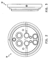
- Fig. 2 illustrates a front elevational view of a detail of the system illustrated in Fig. 1;
- Fig. 3 illustrates a side elevational view of the detail illustrated in Fig. 2;
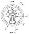
- Fig. 4 illustrates a rear elevational view of the detail illustrated in Figs. 2-3;
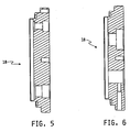
- Fig. 5 illustrates a sectional view of the detail illustrated in Figs. 2-4, taken generally along section lines 5-5 of Fig. 4;
- Fig. 6 illustrates a sectional view of the detail illustrated in Figs. 2-5, taken generally along section lines 6-6 of Fig. 4;
- Fig. 7 illustrates a sectional view of the detail illustrated in Figs. 2-6, taken generally along section lines 7-7 of Fig. 4;
- Fig. 8 illustrates a front elevational view of a detail of the system illustrated in Fig. 1;
- Fig. 9 illustrates a sectional view of the detail illustrated in Fig. 8, taken generally along section lines 9-9 of Fig. 8;
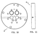
- Fig. 10 illustrates a front elevational view of a detail of the system illustrated in Fig. 1;
- Fig. 11 illustrates a side elevational view of the detail illustrated in Fig. 10;
- Fig. 12 illustrates a rear elevational view of the detail illustrated in Figs. 10-11;
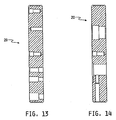
- Fig. 13 illustrates a sectional view of the detail illustrated in Figs. 10-12, taken generally along section lines 13-13 of Fig. 12;
- Fig. 14 illustrates a sectional view of the detail illustrated in Figs. 10-13, taken generally along section lines 14-14 of Fig. 12;
- Fig. 15 illustrates a side elevational view of a detail of the system illustrated in Fig. 1;
- Fig. 16 illustrates a rear elevational view of the detail illustrated in Fig. 15;
- Fig. 17 illustrates a side elevational view of a detail of the system illustrated in Fig. 1;
- Fig. 18 illustrates a rear elevational view of the detail illustrated in Fig. 17;
- Fig. 19 illustrates a longitudinal sectional side elevational view of the detail illustrated in Figs. 17-17;
- Fig. 20 illustrates a longitudinal sectional side elevational view of a detail of the system illustrated in Fig. 1;
- Fig. 21 illustrates a rear elevational view of a detail of the system illustrated in Fig. 1;
- Fig. 22 illustrates a longitudinal sectional side elevational view of the detail illustrated in Fig. 21;
- Fig. 23 illustrates a rear elevational view of a detail of the system illustrated in Fig. 1;
- Fig. 24 illustrates a side elevational view of the detail illustrated in Fig. 23;
- Fig. 25 illustrates a front elevational view of a detail of the system illustrated in Fig. 1;
- Fig. 26 illustrates a longitudinal sectional side elevational view of the detail illustrated in Fig. 25; and,
- Fig. 27 illustrates a fragmentary sectional view of the detail illustrated in Figs.21-22 and the detail illustrated in Figs. 23-24, taken generally along section lines 27-27 of Fig. 21 and Fig. 23.
-
- As used in this application, terms such as "electrically conductive" and "electrically non-insulative" refer to a broad range of conductivities electrically more conductive than materials described as "electrically non-conductive" and "electrically insulative." Terms such as "electrically semiconductive" refer to a broad range of conductivities between electrically conductive and electrically non-conductive. Terms such as "front," "back," "up," "down," and the like, are used only to describe an illustrative embodiment, and are not intended as limiting.
- Coating material particles are typically quite small. Sizes in the range of 5 µm-50 µm are not uncommon. As a result, coating material particles are typically highly penetrating, that is, capable of entering through small openings into, for example, equipment used to dispense them and accumulating there. As a consequence, it is desirable to design coating material dispensing equipment with a view toward being able to clean it without too much difficulty.
- In order to clean powder coating equipment between an interval during which a first color or type of powder coating material is being dispensed and an interval during which a second color or type of powder coating material is being dispensed, cleaning of the powder coating equipment is conducted at intervals. Such cleaning may involve, for example, wiping down of the equipment to dislodge any accumulated powder.
- Additionally, coating material dispensing equipment needs to be designed with a view toward conducting other types of maintenance, routine and otherwise, on the equipment. Maintenance sometimes involves disassembly of covers, or shrouds, which enclose components of the coating material dispensing system, for example, to reduce the exposure of such components to dispensed coating material. Covering of such components has the potential to reduce the amount and complexity of the cleaning which must be conducted on the dispensing equipment. Consequently, a consideration in the design of such shrouds is the ability of the shrouds to protect covered components against the ingress of coating material into the covered components, while at the same time facilitating the removal of the shrouds so that covered components can be serviced as necessary.
- Fig. 1 illustrates a powder gun 10 of the general type of, for example, an RPG-2 dual head robot powder gun model 78772 available from ITW GEMA Automotive Systems, ITW Automotive Finishing Group, 320 Phillips Ave, Toledo, Ohio 43612. Gun 10 includes two side-by-
side nozzles 12, only one of which is illustrated. Eachnozzle 12 is coupled through a respectivepowder delivery tube 14 to a respective inside-the-gun 10 powder hosebarbed fitting 16 mounted in a passageway provided therefor in a robot powder gun rear plate 18 (also see Figs. 2-7). Robot powder gunrear plate 18 is coupled by a threaded robot plate retaining ring 19 (see also Figs. 8-9) to a robot powder gun adapter plate 20 (see also Figs. 10-14). Each ofplates - Powder flows from a
powder source 32 forward throughpowder delivery tube 14 tonozzle 12.Powder source 32 may be of any of a number of known types such as, for example, a fluidized bed of the general type illustrated and described in U. S. Patent 5,768,800. Apowder supply hose 46 extends frompowder source 32 through a robot arm (not shown) to the end of which robot powdergun adapter plate 20 is mounted. Aproximal end 47 ofpowder delivery tube 14 is coupled through a forward manifold 50 (see also Figs. 15-16) to thenozzles 12 mounted onmanifold 50.Powder delivery tube 14 and other gun 10 components are housed betweenmanifold 50 and the robot powder gunrear plate 18. Theforward manifold 50 is supported from therear plate 18 by a number, illustratively two, of support posts 52 (see also Figs. 17-19), 54 (see also Fig. 20) which include appropriate fastening means, such as threaded lugs and threaded holes, to facilitate attachment torear plate 18 andmanifold 50. Support posts 52, 54 may also include (a) cavity(ies), illustrated inpost 54, for housing (a) resistor(s) for coupling between (a) corona ring(s) surroundingnozzles 12 and, for example, a reference potential, such as ground. - An illustratively somewhat right circular
cylindrical shroud 60, surrounds and encloses portions of such powder dispensing equipment,connections 14 and the like. Theshroud 60 includes two portions 62 (see also Figs. 21, 22 and 27), 64 (see also Figs. 23, 24 and 27), which are sometimes referred to hereinafter as alarger portion 62 and asmaller portion 64. Each of theportions larger portion 62 subtends an arc measured about anaxis 66 of thecylinder 60, of somewhat more than 180°, for example, 200°, while thesmaller portion 64 subtends an arc aboutaxis 66, of somewhat less than! 180°, for example, 160°.Shroud portions components shroud 60 during assembly and disassembly. Grooves may be provided in the inner sidewalls ofshroud portions shroud portions shroud portions - A first of the portions, illustratively, the
smaller portion 64, is provided with afeature 70, for example, a somewhat V-bottomed groove, along each of its lateral edges 72. The second of the portions, illustratively, thelarger portion 62, is provided withcomplementary feature 74, illustratively a somewhat V-shaped edge, along each of itslateral edges 76 to cooperate with respective ones of the somewhat V-bottomedgrooves 70 along respectivelateral edges 72 of thefirst portion 64. One or the other or both offeatures gasket material 78, such as, for example, O-ring material, to promote sealing ofportions shroud 60. -
Forward manifold 50 includes a perimetrally extending, rearwardly facingfeature 80, such as a groove or relief for cooperating with complementary forward features 82, illustratively lips, oflarger shroud portion 62 andsmaller shroud portion 64. - At its rearward end, each
shroud portion flange 90 which extends perimetrally partway around its rearward extent.Flanges 90 are interrupted at intervals bypassageways 92 which permit the passage ofrespective tabs 94 of a shroud retainer ring 96 (see also Figs. 25-26). The interior ofshroud retainer ring 96 is sized to receive in a sliding, sealing orientation the assembledshroud components ring 97 may be accommodated in agroove 98 provided therefor around theinterior 100 ofshroud retainer ring 96. Therearwardly facing side 102 of eachflange 90 adjacent eachpassageway 92 is bevelled as illustrated at 104. Thebevel 104 promotes entry of thefinger 94 that projects through thatrespective passageway 92 during assembly of theshroud 60 onto gun 10 into the space between robot powder gunrear plate 18 and theflange 90 to urgefeatures - The claims refer to examples of preferred embodiments of the invention. However, the invention also refers to the use of any single feature and subcombination of features which are disclosed in the claims, the description and/or the drawings.
Claims (10)
- A dispenser including an opening through which coating material is dispensed, a coupling for coupling the opening to a source of coating material to be dispensed, and a shroud for enclosing at least a portion of the dispenser, the shroud including two portions which abut each other at first and second joints which extend generally longitudinally of the shroud.
- The apparatus of claim 1 wherein the shroud comprises a somewhat right cylindrical shroud.
- The apparatus of claim 2 wherein the shroud comprises a somewhat right circular cylindrical shroud.
- The apparatus of claim 3 wherein each of the two portions is part right circular cylindrical.
- The apparatus of any one of claims 1 to 4 wherein the shroud includes a longitudinal axis, a first one of the portions subtends an arc measured about the axis of somewhat more than 180°, and a second one of the portions subtends an arc about the axis of somewhat less than 180°.
- The apparatus of claim 5 wherein the first one of the portions subtends an arc measured about the axis of about 200°, and the second one of the portions subtends an arc measured about the axis of about 160°.
- The apparatus of any one of the preceding claims wherein the shroud portions are constructed from resilient, electrically non-conductive materials.
- The apparatus of any one of the preceding claims wherein a first of the shroud portions includes a lateral edge including a first feature, and a second of the shroud portions includes a lateral edge including a second feature which is complementary to the first feature.
- The apparatus of any one of the preceding claims wherein the dispenser includes a forward end adjacent the opening, the forward end including a feature for cooperating with a feature provided on a forward end of a first one of the shroud portions to facilitate engagement of the forward end of the first one of the shroud portions with the forward end of the dispenser, and a feature for cooperating with a feature provided on a forward end of a second one of the shroud portions to facilitate engagement of the forward end of the second one of the shroud portions with the forward end of the dispenser.
- The apparatus of any one of the preceding claims 1 to 9 wherein the dispenser includes a rearward end including a feature for cooperating with a feature provided on a rearward end of a first one of the shroud portions to facilitate engagement of the rearward end of the first one of the shroud portions with the rearward end of the dispenser, and a feature for cooperating with a feature provided on a rearward end of a second one of the shroud portions to facilitate engagement of the rearward end of the second one of the shroud portions with the rearward end of the dispenser.
Applications Claiming Priority (4)
| Application Number | Priority Date | Filing Date | Title |
|---|---|---|---|
| US50311803P | 2003-09-15 | 2003-09-15 | |
| US503118P | 2003-09-15 | ||
| US10/822,512 US20050056212A1 (en) | 2003-09-15 | 2004-04-12 | Split shroud for coating dispensing equipment |
| US822512 | 2004-04-12 |
Publications (2)
| Publication Number | Publication Date |
|---|---|
| EP1514610A1 true EP1514610A1 (en) | 2005-03-16 |
| EP1514610B1 EP1514610B1 (en) | 2006-10-25 |
Family
ID=34139074
Family Applications (1)
| Application Number | Title | Priority Date | Filing Date |
|---|---|---|---|
| EP04019914A Not-in-force EP1514610B1 (en) | 2003-09-15 | 2004-08-23 | Split shroud for coating dispensing equipment |
Country Status (11)
| Country | Link |
|---|---|
| US (1) | US20050056212A1 (en) |
| EP (1) | EP1514610B1 (en) |
| JP (1) | JP2005087997A (en) |
| KR (1) | KR20050027929A (en) |
| AT (1) | ATE343433T1 (en) |
| CA (1) | CA2479616A1 (en) |
| DE (1) | DE602004002910T2 (en) |
| ES (1) | ES2276198T3 (en) |
| MX (1) | MXPA04008965A (en) |
| PT (1) | PT1514610E (en) |
| TW (1) | TW200523036A (en) |
Cited By (1)
| Publication number | Priority date | Publication date | Assignee | Title |
|---|---|---|---|---|
| EP2139608B1 (en) * | 2007-03-24 | 2011-06-15 | ITW Oberflächentechnik GmbH | Spray gun line connection device |
Families Citing this family (2)
| Publication number | Priority date | Publication date | Assignee | Title |
|---|---|---|---|---|
| DE102010060086A1 (en) * | 2010-10-20 | 2012-04-26 | Sata Gmbh & Co. Kg | Paint application system and method for its operation |
| JP6803730B2 (en) * | 2016-11-22 | 2020-12-23 | 旭サナック株式会社 | Electrostatic coating equipment |
Citations (5)
| Publication number | Priority date | Publication date | Assignee | Title |
|---|---|---|---|---|
| EP0310358A2 (en) * | 1987-09-28 | 1989-04-05 | Illinois Tool Works Inc. | Spray gun for robot mounting |
| EP0459892A1 (en) * | 1990-05-31 | 1991-12-04 | Sames S.A. | Installation for the projection of a controlled flow coating product |
| EP0779105A1 (en) * | 1995-12-15 | 1997-06-18 | ITW Gema AG | Spray coating device for electrostatic spray coating |
| US5716008A (en) * | 1996-03-04 | 1998-02-10 | Nottingham-Spirk Design Associates, Inc. | Trigger sprayer |
| WO2003031075A1 (en) * | 1999-09-16 | 2003-04-17 | Nordson Corporation | Powder spray gun with inline angle spray nozzle |
Family Cites Families (57)
| Publication number | Priority date | Publication date | Assignee | Title |
|---|---|---|---|---|
| DE283832C (en) * | ||||
| US2759763A (en) * | 1952-07-22 | 1956-08-21 | Ransburg Electro Coating Corp | Spray coating apparatus and method |
| US2955565A (en) * | 1956-03-19 | 1960-10-11 | Electro Dispersion Corp | Electrostatic coating apparatus |
| US3102062A (en) * | 1960-03-28 | 1963-08-27 | Stratford Eng Corp | Apparatus for continuous edible oil finishing |
| US4114564A (en) * | 1963-06-13 | 1978-09-19 | Ransburg Corporation | Electrostatic coating apparatus |
| US3233655A (en) * | 1964-05-07 | 1966-02-08 | Stratford Eng Corp | Liquid atomization apparatus |
| FR1589618A (en) * | 1968-10-21 | 1970-03-31 | ||
| FR1594779A (en) * | 1968-11-14 | 1970-06-08 | ||
| US3589607A (en) * | 1969-05-28 | 1971-06-29 | Gourdine Systems Inc | Electrostatic spray gun having an adjustable spray material orifice |
| US3575344A (en) * | 1969-09-22 | 1971-04-20 | Electrostatic Equip Corp | Nozzle and apparatus for electrostatic powder spraying |
| DE2022088C3 (en) * | 1970-05-06 | 1981-04-23 | Graco Inc., Minneapolis, Minn. | Spray gun for applying protective layers made of plastic powder |
| US3684174A (en) * | 1970-06-11 | 1972-08-15 | Georg Wilhelm Bein | Rotating atomizer for electrostatic painting apparatus |
| US3843054A (en) * | 1971-03-22 | 1974-10-22 | Ransburg Electro Coating Corp | Powder apparatus |
| US3913523A (en) * | 1972-08-07 | 1975-10-21 | Ransburg Electro Coating Corp | Powder coating apparatus |
| FR2283729A1 (en) * | 1974-09-06 | 1976-04-02 | Air Ind | ELECTROSTATIC PROJECTION NOZZLE FOR POWDERED PRODUCTS |
| US4169560A (en) * | 1975-03-29 | 1979-10-02 | Elektrostatische Spritz-- und Beflockungsgesellschaft G.F. Vohringer GmbH | Electrostatic spray gun for powdered material |
| CH579951A5 (en) * | 1975-04-11 | 1976-09-30 | Gema Ag | |
| US3964683A (en) * | 1975-09-02 | 1976-06-22 | Champion Spark Plug Company | Electrostatic spray apparatus |
| HU173207B (en) * | 1976-11-10 | 1979-03-28 | Hajtomuevek Es Festoekeszuelek | Rotary head paint sprayer with multi-layer electrode |
| US4135667A (en) * | 1977-03-23 | 1979-01-23 | Hajtomuvek Es Festoberendezesek Gyara | Apparatus for the electrostatic coating of workpieces |
| CH620600A5 (en) * | 1977-05-12 | 1980-12-15 | Alex Hengartner | |
| GB1599303A (en) * | 1977-09-20 | 1981-09-30 | Nat Res Dev | Electrostatic spraying |
| FR2412351A1 (en) * | 1977-12-20 | 1979-07-20 | Air Ind | ELECTROSTATIC PAINTING PROJECTOR WITH BOWL OR ROTATING DISC WITH A PNEUMATIC SEAL |
| USRE31867E (en) * | 1978-02-13 | 1985-04-16 | Nordson Corporation | Electrostatic spray gun |
| US4360155A (en) * | 1979-12-21 | 1982-11-23 | G & R Electro-Powder Coating Corporation | Powder coating distributor |
| DE3005677C2 (en) * | 1980-02-15 | 1982-06-24 | Basf Farben + Fasern Ag, 2000 Hamburg | Method and device for the electrostatic coating of objects with liquids |
| DE3005678C2 (en) * | 1980-02-15 | 1982-06-24 | Basf Farben + Fasern Ag, 2000 Hamburg | Method and device for electrostatic powder coating of objects |
| JPS5921668B2 (en) * | 1980-02-18 | 1984-05-21 | トヨタ自動車株式会社 | Rotary atomization electrostatic coating equipment |
| JPS56141868A (en) * | 1980-04-04 | 1981-11-05 | Toyota Motor Corp | Rotary atomizing electrostatic coating device |
| DE3129151A1 (en) * | 1980-08-06 | 1982-03-18 | National Research Development Corp., London | "DEVICE FOR ELECTROSTATIC SPRAYING OF LIQUID" |
| DE3040136A1 (en) * | 1980-10-24 | 1982-06-03 | Hermann Behr & Sohn Gmbh & Co, 7121 Ingersheim | SPRAYER |
| US4381079A (en) * | 1980-11-03 | 1983-04-26 | Ransburg Corporation | Atomizing device motor |
| US4447008A (en) * | 1980-11-03 | 1984-05-08 | Ransburg Corporation | Atomizing device motor |
| IT1149716B (en) * | 1982-02-02 | 1986-12-10 | Edt Spa | PROCEDURE AND APPARATUS FOR THE ELECTROSTATIC APPLICATION OF LIQUIDS OR POWDERS ON SUBSTANCES AND OBJECTS |
| DE3220796A1 (en) * | 1982-06-03 | 1983-12-08 | Ransburg-Gema AG, 9015 St.Gallen | SPRAYER FOR COATING WITH POWDER |
| DE3379448D1 (en) * | 1982-10-13 | 1989-04-27 | Ici Plc | Electrostatic sprayhead assembly |
| US4505430A (en) * | 1982-11-22 | 1985-03-19 | Ransburg Corporation | Self-cleaning atomizer |
| US4611887A (en) * | 1983-02-24 | 1986-09-16 | Amp Incorporated | Fiber optic connector assembly and wall outlet thereof |
| US4520949A (en) * | 1983-04-11 | 1985-06-04 | Champion Spark Plug Company | Protective housing for coating applicator |
| DE3330665A1 (en) * | 1983-08-25 | 1985-03-14 | Weitmann & Konrad GmbH & Co KG, 7022 Leinfelden-Echterdingen | DEVICE FOR DUSTING MOVING OBJECTS, IN PARTICULAR AREA DOCUMENTS |
| DE3522979A1 (en) * | 1985-06-27 | 1987-01-02 | Bayer Ag | METHOD FOR PRODUCING ELECTRICALLY CHARGED SPRAY MIST FROM CONDUCTIVE LIQUIDS |
| US4685620A (en) * | 1985-09-30 | 1987-08-11 | The University Of Georgia Research Foundation Inc. | Low-volume electrostatic spraying |
| DE3600808A1 (en) * | 1986-01-14 | 1987-07-16 | Esb Voehringer | ELECTROSTATIC POWDER SPRAYING DEVICE WITH TRIBOELECTRIC POWDER CHARGING |
| DE3608415A1 (en) * | 1986-03-13 | 1987-09-24 | Gema Ransburg Ag | ELECTROSTATIC SPRAYING DEVICE FOR COATING POWDER |
| ES2019888B3 (en) * | 1986-03-13 | 1991-07-16 | Ransburg-Gema Ag | ELECTROSTATIC SPRAYER FOR COATING POWDERS. |
| US4785995A (en) * | 1986-03-18 | 1988-11-22 | Mazda Motor Corporation | Methods and apparatus for conducting electrostatic spray coating |
| DE8631764U1 (en) * | 1986-11-27 | 1987-06-25 | Ucosan B.V., Roden, Nl | |
| FR2620354B2 (en) * | 1987-02-12 | 1990-01-05 | Sames Sa | DEVICE FOR ELECTROSTATIC PROJECTION OF POWDERED PRODUCT |
| DE3725172A1 (en) * | 1987-05-27 | 1989-02-09 | Behr Industrieanlagen | METHOD AND SYSTEM FOR ELECTROSTATIC COATING WITH CONDUCTIVE MATERIAL |
| JPH01123033A (en) * | 1987-11-05 | 1989-05-16 | Nippon Steel Corp | Device for coating annealing and separation agent to grain oriented electrical steel strip coil |
| US4890190A (en) * | 1988-12-09 | 1989-12-26 | Graco Inc. | Method of selecting optimum series limiting resistance for high voltage control circuit |
| FR2692173B1 (en) * | 1992-06-10 | 1994-09-02 | Sames Sa | Device for electrostatic projection of a powder coating product with a rotating ionization head. |
| FR2692501B1 (en) * | 1992-06-22 | 1995-08-04 | Sames Sa | DEVICE FOR ELECTROSTATIC PROJECTION OF LIQUID COATING PRODUCT WITH ROTATING SPRAY HEAD. |
| US5433387A (en) * | 1992-12-03 | 1995-07-18 | Ransburg Corporation | Nonincendive rotary atomizer |
| DE19528398A1 (en) * | 1995-08-02 | 1997-02-06 | Gema Volstatic Ag | Electrostatic spraying device for coating material |
| US6328224B1 (en) * | 1997-02-05 | 2001-12-11 | Illinois Tool Works Inc. | Replaceable liner for powder coating apparatus |
| US5853126A (en) * | 1997-02-05 | 1998-12-29 | Illinois Tool Works, Inc. | Quick disconnect for powder coating apparatus |
-
2004
- 2004-04-12 US US10/822,512 patent/US20050056212A1/en not_active Abandoned
- 2004-08-23 ES ES04019914T patent/ES2276198T3/en active Active
- 2004-08-23 AT AT04019914T patent/ATE343433T1/en active
- 2004-08-23 EP EP04019914A patent/EP1514610B1/en not_active Not-in-force
- 2004-08-23 PT PT04019914T patent/PT1514610E/en unknown
- 2004-08-23 DE DE602004002910T patent/DE602004002910T2/en active Active
- 2004-08-26 JP JP2004246919A patent/JP2005087997A/en active Pending
- 2004-08-27 CA CA002479616A patent/CA2479616A1/en not_active Abandoned
- 2004-09-02 TW TW093126550A patent/TW200523036A/en unknown
- 2004-09-14 KR KR1020040073331A patent/KR20050027929A/en not_active Application Discontinuation
- 2004-09-14 MX MXPA04008965A patent/MXPA04008965A/en unknown
Patent Citations (5)
| Publication number | Priority date | Publication date | Assignee | Title |
|---|---|---|---|---|
| EP0310358A2 (en) * | 1987-09-28 | 1989-04-05 | Illinois Tool Works Inc. | Spray gun for robot mounting |
| EP0459892A1 (en) * | 1990-05-31 | 1991-12-04 | Sames S.A. | Installation for the projection of a controlled flow coating product |
| EP0779105A1 (en) * | 1995-12-15 | 1997-06-18 | ITW Gema AG | Spray coating device for electrostatic spray coating |
| US5716008A (en) * | 1996-03-04 | 1998-02-10 | Nottingham-Spirk Design Associates, Inc. | Trigger sprayer |
| WO2003031075A1 (en) * | 1999-09-16 | 2003-04-17 | Nordson Corporation | Powder spray gun with inline angle spray nozzle |
Cited By (1)
| Publication number | Priority date | Publication date | Assignee | Title |
|---|---|---|---|---|
| EP2139608B1 (en) * | 2007-03-24 | 2011-06-15 | ITW Oberflächentechnik GmbH | Spray gun line connection device |
Also Published As
| Publication number | Publication date |
|---|---|
| DE602004002910T2 (en) | 2007-09-06 |
| CA2479616A1 (en) | 2005-03-15 |
| ES2276198T3 (en) | 2007-06-16 |
| PT1514610E (en) | 2007-02-28 |
| JP2005087997A (en) | 2005-04-07 |
| DE602004002910D1 (en) | 2006-12-07 |
| KR20050027929A (en) | 2005-03-21 |
| TW200523036A (en) | 2005-07-16 |
| EP1514610B1 (en) | 2006-10-25 |
| US20050056212A1 (en) | 2005-03-17 |
| MXPA04008965A (en) | 2005-07-01 |
| ATE343433T1 (en) | 2006-11-15 |
Similar Documents
| Publication | Publication Date | Title |
|---|---|---|
| US7128277B2 (en) | Powder bell with secondary charging electrode | |
| US4572438A (en) | Airless spray gun having improved nozzle assembly and electrode circuit connections | |
| CA1323186C (en) | Powder spray gun for quick color change systems | |
| US7815132B2 (en) | Method for preventing voltage from escaping fluid interface for water base gravity feed applicators | |
| US7721976B2 (en) | High speed rotating atomizer assembly | |
| US8096264B2 (en) | Repulsion ring | |
| US8104423B2 (en) | Coating material dispensing apparatus and method | |
| US4186886A (en) | Adapting means providing detachable mounting of an induction-charging adapter head on a spray device | |
| US4771949A (en) | Apparatus for electrostatic coating of objects | |
| EP1514610B1 (en) | Split shroud for coating dispensing equipment | |
| EP0084894B1 (en) | Improvements in or relating to airless spray apparatus | |
| US6758425B2 (en) | Coating-powder spray gun | |
| US6889921B2 (en) | Bell cup skirt | |
| CN112974008A (en) | Electrostatic rotary sprayer and spraying equipment comprising same | |
| US8273417B2 (en) | Spray coating system and method | |
| US20030066911A1 (en) | Spray coating apparatus | |
| EP0745431B1 (en) | Spray gun with anti-back-ionization probe | |
| JPH02503648A (en) | Spray coating equipment for conductive coating liquid | |
| JPH0144111B2 (en) | ||
| CN1689708A (en) | Split shroud for coating material dispensing equipment | |
| EP0827781A3 (en) | Rotary sprayer | |
| US20050023385A1 (en) | Powder robot gun | |
| US20040069870A1 (en) | Triboelectric sprayer | |
| SU1007745A1 (en) | Electrostatic sprayer | |
| JP2024019031A (en) | electrostatic spray device |
Legal Events
| Date | Code | Title | Description |
|---|---|---|---|
| PUAI | Public reference made under article 153(3) epc to a published international application that has entered the european phase |
Free format text: ORIGINAL CODE: 0009012 |
|
| 17P | Request for examination filed |
Effective date: 20040823 |
|
| AK | Designated contracting states |
Kind code of ref document: A1 Designated state(s): AT BE BG CH CY CZ DE DK EE ES FI FR GB GR HU IE IT LI LU MC NL PL PT RO SE SI SK TR |
|
| AX | Request for extension of the european patent |
Extension state: AL HR LT LV MK |
|
| 17Q | First examination report despatched |
Effective date: 20050428 |
|
| AKX | Designation fees paid |
Designated state(s): AT BE BG CH CY CZ DE DK EE ES FI FR GB GR HU IE IT LI LU MC NL PL PT RO SE SI SK TR |
|
| GRAP | Despatch of communication of intention to grant a patent |
Free format text: ORIGINAL CODE: EPIDOSNIGR1 |
|
| GRAS | Grant fee paid |
Free format text: ORIGINAL CODE: EPIDOSNIGR3 |
|
| GRAA | (expected) grant |
Free format text: ORIGINAL CODE: 0009210 |
|
| AK | Designated contracting states |
Kind code of ref document: B1 Designated state(s): AT BE BG CH CY CZ DE DK EE ES FI FR GB GR HU IE IT LI LU MC NL PL PT RO SE SI SK TR |
|
| PG25 | Lapsed in a contracting state [announced via postgrant information from national office to epo] |
Ref country code: FI Free format text: LAPSE BECAUSE OF FAILURE TO SUBMIT A TRANSLATION OF THE DESCRIPTION OR TO PAY THE FEE WITHIN THE PRESCRIBED TIME-LIMIT Effective date: 20061025 Ref country code: CH Free format text: LAPSE BECAUSE OF FAILURE TO SUBMIT A TRANSLATION OF THE DESCRIPTION OR TO PAY THE FEE WITHIN THE PRESCRIBED TIME-LIMIT Effective date: 20061025 Ref country code: LI Free format text: LAPSE BECAUSE OF FAILURE TO SUBMIT A TRANSLATION OF THE DESCRIPTION OR TO PAY THE FEE WITHIN THE PRESCRIBED TIME-LIMIT Effective date: 20061025 Ref country code: SK Free format text: LAPSE BECAUSE OF FAILURE TO SUBMIT A TRANSLATION OF THE DESCRIPTION OR TO PAY THE FEE WITHIN THE PRESCRIBED TIME-LIMIT Effective date: 20061025 Ref country code: SI Free format text: LAPSE BECAUSE OF FAILURE TO SUBMIT A TRANSLATION OF THE DESCRIPTION OR TO PAY THE FEE WITHIN THE PRESCRIBED TIME-LIMIT Effective date: 20061025 Ref country code: CZ Free format text: LAPSE BECAUSE OF FAILURE TO SUBMIT A TRANSLATION OF THE DESCRIPTION OR TO PAY THE FEE WITHIN THE PRESCRIBED TIME-LIMIT Effective date: 20061025 Ref country code: PL Free format text: LAPSE BECAUSE OF FAILURE TO SUBMIT A TRANSLATION OF THE DESCRIPTION OR TO PAY THE FEE WITHIN THE PRESCRIBED TIME-LIMIT Effective date: 20061025 Ref country code: RO Free format text: LAPSE BECAUSE OF FAILURE TO SUBMIT A TRANSLATION OF THE DESCRIPTION OR TO PAY THE FEE WITHIN THE PRESCRIBED TIME-LIMIT Effective date: 20061025 |
|
| REG | Reference to a national code |
Ref country code: GB Ref legal event code: FG4D |
|
| REG | Reference to a national code |
Ref country code: CH Ref legal event code: EP |
|
| REG | Reference to a national code |
Ref country code: IE Ref legal event code: FG4D |
|
| REF | Corresponds to: |
Ref document number: 602004002910 Country of ref document: DE Date of ref document: 20061207 Kind code of ref document: P |
|
| PG25 | Lapsed in a contracting state [announced via postgrant information from national office to epo] |
Ref country code: DK Free format text: LAPSE BECAUSE OF FAILURE TO SUBMIT A TRANSLATION OF THE DESCRIPTION OR TO PAY THE FEE WITHIN THE PRESCRIBED TIME-LIMIT Effective date: 20070125 Ref country code: BG Free format text: LAPSE BECAUSE OF FAILURE TO SUBMIT A TRANSLATION OF THE DESCRIPTION OR TO PAY THE FEE WITHIN THE PRESCRIBED TIME-LIMIT Effective date: 20070125 |
|
| REG | Reference to a national code |
Ref country code: SE Ref legal event code: TRGR |
|
| REG | Reference to a national code |
Ref country code: PT Ref legal event code: SC4A Free format text: AVAILABILITY OF NATIONAL TRANSLATION Effective date: 20070124 |
|
| REG | Reference to a national code |
Ref country code: CH Ref legal event code: PL |
|
| ET | Fr: translation filed | ||
| REG | Reference to a national code |
Ref country code: ES Ref legal event code: FG2A Ref document number: 2276198 Country of ref document: ES Kind code of ref document: T3 |
|
| PLBE | No opposition filed within time limit |
Free format text: ORIGINAL CODE: 0009261 |
|
| STAA | Information on the status of an ep patent application or granted ep patent |
Free format text: STATUS: NO OPPOSITION FILED WITHIN TIME LIMIT |
|
| 26N | No opposition filed |
Effective date: 20070726 |
|
| PG25 | Lapsed in a contracting state [announced via postgrant information from national office to epo] |
Ref country code: GR Free format text: LAPSE BECAUSE OF FAILURE TO SUBMIT A TRANSLATION OF THE DESCRIPTION OR TO PAY THE FEE WITHIN THE PRESCRIBED TIME-LIMIT Effective date: 20070126 Ref country code: MC Free format text: LAPSE BECAUSE OF NON-PAYMENT OF DUE FEES Effective date: 20070831 |
|
| PG25 | Lapsed in a contracting state [announced via postgrant information from national office to epo] |
Ref country code: IE Free format text: LAPSE BECAUSE OF NON-PAYMENT OF DUE FEES Effective date: 20070823 |
|
| PG25 | Lapsed in a contracting state [announced via postgrant information from national office to epo] |
Ref country code: EE Free format text: LAPSE BECAUSE OF FAILURE TO SUBMIT A TRANSLATION OF THE DESCRIPTION OR TO PAY THE FEE WITHIN THE PRESCRIBED TIME-LIMIT Effective date: 20061025 |
|
| PG25 | Lapsed in a contracting state [announced via postgrant information from national office to epo] |
Ref country code: CY Free format text: LAPSE BECAUSE OF FAILURE TO SUBMIT A TRANSLATION OF THE DESCRIPTION OR TO PAY THE FEE WITHIN THE PRESCRIBED TIME-LIMIT Effective date: 20061025 Ref country code: LU Free format text: LAPSE BECAUSE OF NON-PAYMENT OF DUE FEES Effective date: 20070823 |
|
| PG25 | Lapsed in a contracting state [announced via postgrant information from national office to epo] |
Ref country code: HU Free format text: LAPSE BECAUSE OF FAILURE TO SUBMIT A TRANSLATION OF THE DESCRIPTION OR TO PAY THE FEE WITHIN THE PRESCRIBED TIME-LIMIT Effective date: 20070426 Ref country code: TR Free format text: LAPSE BECAUSE OF FAILURE TO SUBMIT A TRANSLATION OF THE DESCRIPTION OR TO PAY THE FEE WITHIN THE PRESCRIBED TIME-LIMIT Effective date: 20061025 |
|
| PGFP | Annual fee paid to national office [announced via postgrant information from national office to epo] |
Ref country code: AT Payment date: 20110731 Year of fee payment: 8 Ref country code: GB Payment date: 20110825 Year of fee payment: 8 Ref country code: FR Payment date: 20110830 Year of fee payment: 8 Ref country code: SE Payment date: 20110829 Year of fee payment: 8 Ref country code: PT Payment date: 20110804 Year of fee payment: 8 Ref country code: DE Payment date: 20110830 Year of fee payment: 8 Ref country code: ES Payment date: 20110826 Year of fee payment: 8 |
|
| PGFP | Annual fee paid to national office [announced via postgrant information from national office to epo] |
Ref country code: IT Payment date: 20110823 Year of fee payment: 8 Ref country code: NL Payment date: 20110901 Year of fee payment: 8 Ref country code: BE Payment date: 20110825 Year of fee payment: 8 |
|
| BERE | Be: lapsed |
Owner name: ILLINOIS TOOL WORKS INC. Effective date: 20120831 |
|
| REG | Reference to a national code |
Ref country code: PT Ref legal event code: MM4A Free format text: LAPSE DUE TO NON-PAYMENT OF FEES Effective date: 20130225 |
|
| REG | Reference to a national code |
Ref country code: NL Ref legal event code: V1 Effective date: 20130301 |
|
| REG | Reference to a national code |
Ref country code: SE Ref legal event code: EUG |
|
| REG | Reference to a national code |
Ref country code: AT Ref legal event code: MM01 Ref document number: 343433 Country of ref document: AT Kind code of ref document: T Effective date: 20120823 |
|
| GBPC | Gb: european patent ceased through non-payment of renewal fee |
Effective date: 20120823 |
|
| PG25 | Lapsed in a contracting state [announced via postgrant information from national office to epo] |
Ref country code: SE Free format text: LAPSE BECAUSE OF NON-PAYMENT OF DUE FEES Effective date: 20120824 Ref country code: NL Free format text: LAPSE BECAUSE OF NON-PAYMENT OF DUE FEES Effective date: 20130301 |
|
| REG | Reference to a national code |
Ref country code: FR Ref legal event code: ST Effective date: 20130430 |
|
| PG25 | Lapsed in a contracting state [announced via postgrant information from national office to epo] |
Ref country code: PT Free format text: LAPSE BECAUSE OF NON-PAYMENT OF DUE FEES Effective date: 20130225 Ref country code: IT Free format text: LAPSE BECAUSE OF NON-PAYMENT OF DUE FEES Effective date: 20120823 Ref country code: BE Free format text: LAPSE BECAUSE OF NON-PAYMENT OF DUE FEES Effective date: 20120831 |
|
| PG25 | Lapsed in a contracting state [announced via postgrant information from national office to epo] |
Ref country code: AT Free format text: LAPSE BECAUSE OF NON-PAYMENT OF DUE FEES Effective date: 20120823 |
|
| PG25 | Lapsed in a contracting state [announced via postgrant information from national office to epo] |
Ref country code: DE Free format text: LAPSE BECAUSE OF NON-PAYMENT OF DUE FEES Effective date: 20130301 Ref country code: GB Free format text: LAPSE BECAUSE OF NON-PAYMENT OF DUE FEES Effective date: 20120823 |
|
| PG25 | Lapsed in a contracting state [announced via postgrant information from national office to epo] |
Ref country code: FR Free format text: LAPSE BECAUSE OF NON-PAYMENT OF DUE FEES Effective date: 20120831 |
|
| REG | Reference to a national code |
Ref country code: DE Ref legal event code: R119 Ref document number: 602004002910 Country of ref document: DE Effective date: 20130301 |
|
| REG | Reference to a national code |
Ref country code: ES Ref legal event code: FD2A Effective date: 20131021 |
|
| PG25 | Lapsed in a contracting state [announced via postgrant information from national office to epo] |
Ref country code: ES Free format text: LAPSE BECAUSE OF NON-PAYMENT OF DUE FEES Effective date: 20120824 |