EP2139302B1 - High-voltage plasma producing apparatus - Google Patents
High-voltage plasma producing apparatus Download PDFInfo
- Publication number
- EP2139302B1 EP2139302B1 EP08738986.2A EP08738986A EP2139302B1 EP 2139302 B1 EP2139302 B1 EP 2139302B1 EP 08738986 A EP08738986 A EP 08738986A EP 2139302 B1 EP2139302 B1 EP 2139302B1
- Authority
- EP
- European Patent Office
- Prior art keywords
- electrode
- alternating
- voltage
- current signal
- electric
- Prior art date
- Legal status (The legal status is an assumption and is not a legal conclusion. Google has not performed a legal analysis and makes no representation as to the accuracy of the status listed.)
- Not-in-force
Links
Images

Classifications
-
- F—MECHANICAL ENGINEERING; LIGHTING; HEATING; WEAPONS; BLASTING
- F01—MACHINES OR ENGINES IN GENERAL; ENGINE PLANTS IN GENERAL; STEAM ENGINES
- F01N—GAS-FLOW SILENCERS OR EXHAUST APPARATUS FOR MACHINES OR ENGINES IN GENERAL; GAS-FLOW SILENCERS OR EXHAUST APPARATUS FOR INTERNAL-COMBUSTION ENGINES
- F01N3/00—Exhaust or silencing apparatus having means for purifying, rendering innocuous, or otherwise treating exhaust
- F01N3/08—Exhaust or silencing apparatus having means for purifying, rendering innocuous, or otherwise treating exhaust for rendering innocuous
- F01N3/0892—Electric or magnetic treatment, e.g. dissociation of noxious components
-
- F—MECHANICAL ENGINEERING; LIGHTING; HEATING; WEAPONS; BLASTING
- F01—MACHINES OR ENGINES IN GENERAL; ENGINE PLANTS IN GENERAL; STEAM ENGINES
- F01N—GAS-FLOW SILENCERS OR EXHAUST APPARATUS FOR MACHINES OR ENGINES IN GENERAL; GAS-FLOW SILENCERS OR EXHAUST APPARATUS FOR INTERNAL-COMBUSTION ENGINES
- F01N3/00—Exhaust or silencing apparatus having means for purifying, rendering innocuous, or otherwise treating exhaust
- F01N3/08—Exhaust or silencing apparatus having means for purifying, rendering innocuous, or otherwise treating exhaust for rendering innocuous
- F01N3/10—Exhaust or silencing apparatus having means for purifying, rendering innocuous, or otherwise treating exhaust for rendering innocuous by thermal or catalytic conversion of noxious components of exhaust
- F01N3/18—Exhaust or silencing apparatus having means for purifying, rendering innocuous, or otherwise treating exhaust for rendering innocuous by thermal or catalytic conversion of noxious components of exhaust characterised by methods of operation; Control
- F01N3/20—Exhaust or silencing apparatus having means for purifying, rendering innocuous, or otherwise treating exhaust for rendering innocuous by thermal or catalytic conversion of noxious components of exhaust characterised by methods of operation; Control specially adapted for catalytic conversion
-
- H—ELECTRICITY
- H05—ELECTRIC TECHNIQUES NOT OTHERWISE PROVIDED FOR
- H05H—PLASMA TECHNIQUE; PRODUCTION OF ACCELERATED ELECTRICALLY-CHARGED PARTICLES OR OF NEUTRONS; PRODUCTION OR ACCELERATION OF NEUTRAL MOLECULAR OR ATOMIC BEAMS
- H05H1/00—Generating plasma; Handling plasma
- H05H1/24—Generating plasma
- H05H1/46—Generating plasma using applied electromagnetic fields, e.g. high frequency or microwave energy
-
- F—MECHANICAL ENGINEERING; LIGHTING; HEATING; WEAPONS; BLASTING
- F01—MACHINES OR ENGINES IN GENERAL; ENGINE PLANTS IN GENERAL; STEAM ENGINES
- F01N—GAS-FLOW SILENCERS OR EXHAUST APPARATUS FOR MACHINES OR ENGINES IN GENERAL; GAS-FLOW SILENCERS OR EXHAUST APPARATUS FOR INTERNAL-COMBUSTION ENGINES
- F01N2240/00—Combination or association of two or more different exhaust treating devices, or of at least one such device with an auxiliary device, not covered by indexing codes F01N2230/00 or F01N2250/00, one of the devices being
- F01N2240/28—Combination or association of two or more different exhaust treating devices, or of at least one such device with an auxiliary device, not covered by indexing codes F01N2230/00 or F01N2250/00, one of the devices being a plasma reactor
-
- H—ELECTRICITY
- H05—ELECTRIC TECHNIQUES NOT OTHERWISE PROVIDED FOR
- H05H—PLASMA TECHNIQUE; PRODUCTION OF ACCELERATED ELECTRICALLY-CHARGED PARTICLES OR OF NEUTRONS; PRODUCTION OR ACCELERATION OF NEUTRAL MOLECULAR OR ATOMIC BEAMS
- H05H2242/00—Auxiliary systems
- H05H2242/20—Power circuits
- H05H2242/26—Matching networks
-
- H—ELECTRICITY
- H05—ELECTRIC TECHNIQUES NOT OTHERWISE PROVIDED FOR
- H05H—PLASMA TECHNIQUE; PRODUCTION OF ACCELERATED ELECTRICALLY-CHARGED PARTICLES OR OF NEUTRONS; PRODUCTION OR ACCELERATION OF NEUTRAL MOLECULAR OR ATOMIC BEAMS
- H05H2245/00—Applications of plasma devices
- H05H2245/10—Treatment of gases
- H05H2245/17—Exhaust gases
Definitions
- the present invention relates to a high-voltage plasma generating apparatus for generating a plasma using a high voltage of 10 2 -10 5 V at a high frequency band of e.g., 100MHz-10GHz.
- the present invention relates to an apparatus preferably usable in a variety of fields of e.g., an apparatus for executing an oxidation treatment of NO (nitric oxide) included in the exhaust gas from e.g., a diesel engine.
- the treatment apparatus using high-voltage plasma in the atmospheric pressure, has been recently proposed for executing an oxidation treatment of NO included in the exhaust gas from e.g., a diesel engine.
- a voltage conversion transformer often used under a condition of a low frequency band equal to or less than 10MHz, is used for generating high-voltage plasma
- a coiled coil is required to be small in the size and the number of turn thereof. This is because inductance (reactance) should be small at a high frequency wave of 100MHz or greater.
- the coil, used as an electric cable is accordingly required to have small diameter. Consequently, a drawback occurred that large power cannot be supplied.
- the following non-patent document 1 proposes a parallel-plates type of high-voltage plasma generating apparatus.
- the parallel-plates type of the high-voltage plasma generating apparatus is configured to generate plasma in an area between electrodes by applying a high-voltage pulse to the electrodes with the use of an electric oscillator for executing oxidation of NO included in the exhaust gas from e.g., an engine.
- the frequency of the high-voltage pulse is several kHz, and the peak voltage thereof is 5000-10000V.
- Non-patent Document 1 " Complete NOx Removal Technology Using Nonequilibrium Plasma and Chemical Process (Performances of Ordinary and Barrier Type Plasma Reactors),” Transactions of the Japan Society of Mechanical Engineers, 66-646B, 1501-1506 (2000 ).
- the aforementioned parallel-plates type of the apparatus has had a drawback that sufficient power is not supplied to the electrodes. This is because a part of the supplied electric power is reflected due to lack of impedance matching, so that enough electric power cannot be fed. Furthermore, for the high-voltage pulses of several KHz , the discharge duration time of a high-voltage pulse takes short, and an interval time until a next high-voltage pulses is followed takes long. In this case, electrons, once ionized from gas, will recombine therewith. It is therefore necessary to provide a great deal of energy for ionizing electrons every time the high-voltage pulse is applied. Consequently, the aforementioned parallel-plate apparatus has had low power efficiency. Because of this, the parallel-plates type of the apparatus also has a drawback that the amount of oxidization-processed NO per unit time turns out to be small for the input power.
- an object of the present invention is to provide a high-voltage plasma generating apparatus for generating high-voltage plasma usable in e.g., a NO oxidization processing apparatus for solving the aforementioned drawbacks.
- the high-voltage plasma generating apparatus is capable of efficiently generating high-voltage plasma while reducing the input power less than that of the conventional art.
- the present invention provides a high-voltage plasma generating apparatus for generating plasma using high voltage of 10 2 -10 5 V.
- the apparatus includes a first electrode, a second electrode and a control device.
- the first electrode receives, as electric power, feeding of an alternating-current signal including a signal component of a predetermined frequency from an electric feeding point, to generate high voltage due to resonance which is occurred upon the feeding of the alternating-current signal.
- the second electrode is grounded and spaced away from the first electrode and encloses the first electrode, to define a space around the first electrode.
- the control device is configured to adjust an alternating-current signal including a signal component which is identical to a resonance frequency of the first electrode, to be fed to the first electrode.
- the control device includes: an electric field probe which measures intensity of an electric field to be generated in the space between the first electrode and the second electrode; a filter which filters a measurement signal from the electric field probe, to obtain an alternating-current signal of a band of the predetermined frequency; a variable phase shifter which shifts a phase of the alternating-current signal to synchronize the alternating-current signal to the resonance of the electric field to be generated in the space when the alternating-current signal is fed to the first electrode as the electric power; and an amplifier which amplifies the phase-shifted alternating-current signal.
- the control device is configured to feed the amplified alternating-current signal to the first electrode as the electric power to be inputted.
- control unit desirably further includes an amplitude modulator which modulates amplitude of the alternating-current signal in order to control increase and decrease of the plasma to be generated in the space. Additionally, the control unit preferably detects the measurement signal outputted from the electric field probe, monitors a condition of the electric field or the generated plasma, and controls at least one of the variable phase shifter and the amplitude modulator in accordance with a monitoring result
- the first electrode is a linear electrode elongated in a direction
- the space defined by the second electrode is elongated around the first electrode
- separation distance from both ends of the linear electrode to the grounded electrode is shorter than separation distance from other portion of the linear electrode excluding the both ends to the grounded electrode.
- the control device has a feedback system configured to filter the measurement signal used for measuring the electric field generated in the space between the first electrode and the second electrode, shift the phase of the alternating-current signal obtained through the filtering, amplify the alternating-current signal, and feeding the amplified alternating-current signal to the first electrode as the alternating-current electric power.
- the feedback system it is possible to adjust the alternating-current signal to be fed in accordance with resonance frequency change caused by plasma generation. In this case, the signal, synchronized with the resonance, is fed as electric power. Therefore, it is possible to easily increase the resonance.
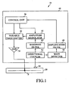
- FIG. 1 is a schematic block diagram of the high-voltage plasma generating apparatus (hereinafter simply referred to as "apparatus") 10.
- the apparatus 10 includes a reactor 20 for generating high-voltage plasma and a control device 40.
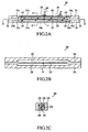
- the reactor 20 is illustrated in Figs. 2A to 2C.
- Figure 2A is a cross-sectional side view of the reactor 20.
- Figure 2B is a cross-sectional view of the reactor 20 sectioned along Arrow B-B' in Fig. 2A.
- Figure 2C is a cross-sectional view of the reactor 20 sectioned along Arrow A-A' in Fig. 2A .
- the reactor 20 is a rod-shaped device.
- the reactor 20 is mainly composed of a liner electrode (first electrode) 22, a pair of grounded electrodes (second electrodes) 24, a pair of dielectrics 26, a feeding connection terminal 28 and an electric field probe 30.
- the linear electrode 22 is an electrode elongated in one direction.
- the linear electrode 22 is disposed in an interior space 24b along the wall surfaces of the grounded electrodes 24.
- the linear electrode 22 is spaced away from the wall surfaces of the grounded electrodes 24 through constant distance.
- Each of the grounded electrodes 24 has a recess 24a.
- the interior space 24b is formed by disposing the recesses 24a of the pair of the grounded electrodes 24 to be positioned opposite to each other.
- the linear electrode 22 is sandwitched between the pair of the elongated plate-shaped dielectrics 26, and forms a strip line.
- a micro strip line and a center conductor of a coaxial cable may be used instead of the strip line.
- High conductive material e.g., silver, copper and aluminium, is preferably used as the linear electrode 22.
- the linear electrode 22 is a strip line with length 21.
- An electric feeding point F is set in a position slightly out-of-alignment with the longitudinal center of the linear electrode 22, specifically, in a position determined by the aforementioned formula (1).
- an AC (alternating-current) signal is applied to the electric feeding point F from an electric feeding line 29 via the feeding connection terminal 28.
- the electric feeding point F is set in a position slightly out-of-alignment with the longitudinal center of the linear electrode 22 for achieving impedance matching in the electric feeding of the reactor 20.
- the linear electrode 22 is capable of efficiently generating high voltage because resonance of the lowest-order mode is therein occurred similarly to an AC dipole antenna when half a wave length A of a transmission signal transmitting through the linear electrode 22 gets matched with the length 2I of the linear electrode 22.
- the length 2I is an important factor for determining a resonance frequency in the apparatus 10.
- the length 2I is set for effectively generating high voltage at a frequency band of 100MHz-10GHz.
- high heat-resistant dielectric material with low dielectric loss such as silica glass and ceramic containing alumina and boron nitride, is preferably used as the dielectrics 26.
- the pair of the grounded electrodes 24 enclose the linear electrode 22, and are grounded. Specifically, the pair of grounded electrodes 24, 24 are opposed to each other. Additionally, the recesses 24a, formed on the inner surfaces of the opposed pair of the grounded electrodes 24, 24, define the interior space 24b.
- the linear electrode 22, sandwitched between the pair of the dielectrics 26, is disposed in the interior space 24b. The pair of the dielectrics 26 are therein fixed while making contact with the inner surfaces of the grounded electrodes 24. Therefore, the interior space 24b is formed for enclosing the linear electrode 22, and the linear electrode 22 is spaced away from the grounded electrode 24.
- High-conductive material e.g., silver, copper and aluminum is preferably used as the grounded electrode 24.
- the most portion of the linear electrode 22, excluding the both ends 22a and 22b, is spaced away from the pair of the earth electrodes 24 by a constant separation distance.
- a separation distance in each of the both ends 22a and 22b of the linear electrode 22 is shorter than that in the other portion of the linear electrode 22 excluding the both ends 22a and 22b.
- discharging protrusions 25 are provided on each of the grounded electrodes 24 for opposing to the both ends 22a and 22b of the liner electrode 22. Accordingly, the separation distance from the both ends 22a and 22b of the linear electrode 22 to each of the grounded electrodes 24 is shorter than the aforementioned constant separation distance.
- Conductive material or high-dielectric material is used as the discharging protrusions 25.
- the separation distance herein means the shortest distance from an arbitrary position of interest in the linear electrode 22 to each of the grounded electrodes 24.
- the separation distance from positions in the both ends 22a and 22b of the linear electrode 22 to each of the grounded electrode 24 is set to be shorter than that from a position in the other portion of the linear electrode 22 excluding the both ends 22a and 22b to each of the grounded electrodes 24, such that voltage in the both ends 22a and 22b of the linear electrode 22 is maximized and plasma is efficiently generated therearound.
- the feeding connection terminal 28 is disposed on one of the earth electrodes 24 for connecting the electric feeding line 29 to the electric feeding point F of the linear electrode 22.
- the electric feeding line 29 is insulated from the grounded electrode 24 through an insulation member.
- the grounded electrodes 24 are opposed to each other, and apertures 32 are formed on the both ends of the reactor 20 (i.e., horizontal ends of the reactor 20 in Fig. 2A ).
- the apertures 32 communicate with the external atmosphere or external apparatus and link to the interior space 24b.
- the apparatus 10 is used for executing oxidation of NO included in the exhaust gas from e.g., a diesel engine, the exhaust gas is introduced thereto through one of the apertures 32.
- the introduced NO and the like are oxidized therein using high-voltage plasma.
- the oxidized NO and the like are discharged to the external atmosphere through the other of the apertures 32.
- diameters of the apertures 32 are set to be extremely smaller than the length 2I of the linear electrode 22 for preventing leakage of an electromagnetic wave generated in the interior space 24b to the outside.
- the maximum width of the cross-section D of each aperture 32 is set to be extremely smaller than " ⁇ /2," which is half the wave length A.
- the electric field probe 30 is a sensor which detects an electric field in the interior space 24b and output a measurement signal proportional to the intensity of the electric field.
- the electric field probe 30 is disposed in one of the earth electrodes 24.
- a heretofore known electric field probe is used as the electric field probe 30.
- the measurement signal, outputted from the electric field probe 30, is transmitted to a control device 40.
- the control device 40 is configured to adjust the measurement signal obtained from the electric field probe 30 through predetermined processing and subsequently feed the adjusted signal to the linear electrode 22 as electric power.
- the control device 40 is composed of a directional coupler 42, a band-pass filter 44, a wave detector 46, an amplification filter 48, an amplitude modulator 50, a variable phase shifter 52, an amplifier 54 and a control unit 56.
- the directional coupler 42 is a section configured to divide the measurement signal, which is outputted from the electric field probe 30, into two components.
- One of the divided measurement signal components is transmitted to the control unit 56 via the wave detector 46 and the amplification filter 48, whereas the other of the divided measurement signal components is transmitted to the band-path filter 44.
- the band-pass filter 44 is used for extracting the wave length of the same frequency band as the resonance frequency out of the measurement signal outputted from the electric field probe 30.
- the resonance frequency band is preliminarily set. When the resonance frequency is set to be 100MHz, for instance, the frequency band of the band-pass filter 44 is accordingly set to be 50-150MHz.
- An AC signal, obtained by the band-pass filter 44 is transmitted to the amplitude modulator 50.
- the amplitude modulator 50 is a section configured to execute amplitude modulation of the AC signal transmitted from the band-pass filter 44 for controlling the generation amount of plasma by varying the duty ratio of the AC signal.
- the amplitude modulator 50 is used in an apparatus for executing oxidation of NO (nitric oxide) included in the exhaust gas, the amount of oxidation-processed NO is controlled by varying the generation amount of plasma through the variation of the duty ratio of a signal.
- the duty ration is set to be higher in proportion to the amount of the discharge gas.
- the amplitude modulation frequency is set to be approximately several kHz-1MHz.
- the variable phase shifter 52 is a section configured to execute predetermined phase shift of the amplitude-modulated AC signal. As hereinafter described, when the amplified AC signal is supplied to the electric feeding point F as an electric current (voltage) to be fed, the phase shift, executed by the variable phase shifter 52, is controlled for shifting the phase of the amplified AC signal for the signal to become in phase with an electric current (voltage) in resonance generated in the reactor 20. In other words, the phase shift is controlled for making the amplified AC signal in synchronization with the resonance in the electric field.
- the amount of the phase shift is set on a basis of the transmission time of the signal transmitting through a line corresponding to the feedback path from the electric field probe 30 to the electric feeding point F and the delay time required for processes.
- the amplifier 54 is a section to amplify the phase-shifted AC signal at predetermined-fold magnification and supply the amplified AC signal to the electric feeding point F as an electric current.
- amplitude modulation and the phase shift are respectively executed in accordance with a control signal from the control unit 56.
- the control unit 56 is configured to monitor the measurement signal supplied thereto via the wave detector 46 and the amplification filter 48, determine the amplitude modulation and the phase shift in accordance with the monitoring result, and generate a control signal.
- the monitoring processing for instance, the intensity of the electric field in the resonance frequency is obtained, and a condition of the electric field or a condition of the generated plasma is assessed based on the intensity of the electric field. Furthermore, whether the resonance is increasing or decreasing is estimated.
- the wave detector 46 is a section configured to detect the measurement signal based on a reference signal, that is, a preliminarily-set signal having the same frequency as a resonance frequency.
- the amplification filter 48 amplifies the detected measurement signal, filtering the amplified signal for selectively allowing a predetermined frequency component, and transmit the predetermined frequency component to the control unit 56.
- the present invention is configured to execute the amplitude modulation of the measurement signal measured by the electric field probe 30 which detects the intensity of the electric field in the reactor 20, and feedback the AC signal which is obtained through the phase shift, to the reactor 20 as electric power to be fed.
- the apparatus 10 is configured to generate high-voltage output using a feedback system without including an oscillator.
- a noise component e.g., thermal noise
- the signal triggers generation of a weak resonance, and the weak resonance is improved by the electric feeding using the feedback system. Note it is possible to increase high-voltage output by cooling the surrounding of the grounded electrodes 24 using liquid nitrogen or liquid helium.
- FIGS. 3A and 3B are diagrams illustrating transmission line models representing a resonance system of the liner electrode 22. As illustrated in Fig. 3A , the transmission line model is represented using a pair of transmission lines parallelly disposed along axes thereof. The position of the electric feeding point F is herein defined as "x 0 ".
- the formula (5) is a quadratic partial differential equation having voltage V as an unknown. In this case, the electric conductivity of plasma is lower than that of the transmission line. Therefore, the equivalent resistance R of the transmission line should not be herein considered.
- the series expansion is herein conducted for a delta function ⁇ (x-x0). In conjunction with this, the series expansion is also conducted for the voltage V as shown in the following formula (7).
- Solution of the formula (5) is herein represented by the following formula (8).
- the following formula (10) more simply represents the formula (9).
- distribution of an electric current is represented by the following formula (11).
- the apparatus 10 is configured to have the maximum voltage in the both ends 22a and 22b of the linear electrode 22 (see Fig. 2A ) under the lowest-order resonant mode.
- the separation distance from the both ends 22a and 22b to each of the grounded electrodes 24 is shorter than the separation distance from the other portion of the linear electrode 22 and each of the grounded electrodes 24. Accordingly, plasma is more likely to be generated.
- l 0 t l 00 ⁇ e i ⁇ t
- V n ⁇ Q t ⁇ n i ⁇ ⁇ ⁇ n Cr ⁇ I QQ ⁇ e i ⁇ t sin ⁇ x 2 l - ⁇ 2 + ⁇ ⁇ 0 2 + i x ⁇ 2
- V n
- input impedance Z in seen on the transmission line from the input side to the load side, is represented by the following formula (12).
- load means plasma discharge load.
- Z r represents load impedance of the discharge load
- Z c represents characteristic impedance of the transmission line.
- Z 00 represents input impedance on the electric feeding line.
- Z x Z e ⁇ Z r + Z e tan yx Z c + Z r tanh yx
- Z e L C ⁇ L Cr ⁇ 1 + l ⁇ x 2
- y - ⁇ 2 ⁇ L ⁇ C ⁇ l ⁇ ⁇ L ⁇ Cr ⁇ 1 - i ⁇ x 2
- Z 00 1 Z lop + 1 Z huo
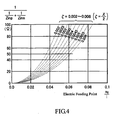
- Figure 4 illustrates a relation between an electric feeding position and input impedance when the transmission line models, illustrated in Figs. 3A and 3B , are used.
- impedance of an electric feeding line is set to be 50 ⁇ . Therefore, when it is checked if the position x 0 of the electric feeding point F, in which the impedance is 50 ⁇ , is found while the value of X /2 is varied in a range of 0.002-0.006, Fig.
- the position x 0 of the electric feeding point F is represented by a value of "x 0 /l ("I" is half the length of the linear electrode 22)."
- the value of x 0 /l is equal to or less than 0.1. Accordingly, when X is determined, it is possible to uniquely compute the out-of-alignment amount x 0 as shown in the formula (1). Furthermore, it is possible to determine the position of the electric feeding point F based on the out-of-alignment amount x 0 .
- the position x 0 of the electric feeding point F for achieving the impedance matching depends on the equivalent inductance L, the equivalent capacitance C and the equivalent resistance R in the resonance system of the reactor 20. Values thereof vary depending on conditions of use. Therefore, it is desirable to determine the position x 0 of the electric feeding point F in the manufacturing process of the apparatus 10, specifically, after a condition of use of the reactor 20 is confirmed.
- a measurement signal, measured by the electric field probe 30, is processed and the processed signal is again fed as electric power to the linear electrode 22 in which resonance is generated. Accordingly, amplitude is amplified by the resonance. Therefore, it is possible to easily generate high voltage that the maximum voltage thereof is 10 2 -10 5 V in the voltage distribution represented by the formula (10).
- the position of the electric feeding position F in which the impedance matching is achieved, is limited.
- the position of the electric feeding position F is desirably set to be out-of-alignment with the center position at the out-of-alignment amount x 0 defined by the formula (1). For the position, the impedance matching is achieved and it is accordingly possible to efficiently feed electric power. In other words, it is possible to easily generate high voltage in which 10 2 to 10 5 V is reached as the maximum voltage thereof without using a conventionally used oscillator.
- the high-voltage plasma generating apparatus has been explained in detail.
- the present invention is not limited to the aforementioned embodiment.
- a variety of changes and modifications may be arbitrarily done for the aforementioned embodiment without departing from the scope of the present invention as defined in the appended claims.
- NO nitric oxide
Landscapes
- Engineering & Computer Science (AREA)
- Chemical & Material Sciences (AREA)
- Chemical Kinetics & Catalysis (AREA)
- Physics & Mathematics (AREA)
- Plasma & Fusion (AREA)
- Health & Medical Sciences (AREA)
- Toxicology (AREA)
- Combustion & Propulsion (AREA)
- Mechanical Engineering (AREA)
- General Engineering & Computer Science (AREA)
- Spectroscopy & Molecular Physics (AREA)
- Electromagnetism (AREA)
- Plasma Technology (AREA)
- Treating Waste Gases (AREA)
- Physical Or Chemical Processes And Apparatus (AREA)
Applications Claiming Priority (2)
| Application Number | Priority Date | Filing Date | Title |
|---|---|---|---|
| JP2007083657 | 2007-03-28 | ||
| PCT/JP2008/055836 WO2008123346A1 (ja) | 2007-03-28 | 2008-03-27 | 高電圧プラズマ発生装置 |
Publications (3)
| Publication Number | Publication Date |
|---|---|
| EP2139302A1 EP2139302A1 (en) | 2009-12-30 |
| EP2139302A4 EP2139302A4 (en) | 2011-11-30 |
| EP2139302B1 true EP2139302B1 (en) | 2013-09-25 |
Family
ID=39830834
Family Applications (1)
| Application Number | Title | Priority Date | Filing Date |
|---|---|---|---|
| EP08738986.2A Not-in-force EP2139302B1 (en) | 2007-03-28 | 2008-03-27 | High-voltage plasma producing apparatus |
Country Status (7)
| Country | Link |
|---|---|
| US (1) | US8551414B2 (da) |
| EP (1) | EP2139302B1 (da) |
| JP (1) | JP4288308B2 (da) |
| KR (1) | KR100931622B1 (da) |
| CN (1) | CN101606443B (da) |
| DK (1) | DK2139302T3 (da) |
| WO (1) | WO2008123346A1 (da) |
Families Citing this family (8)
| Publication number | Priority date | Publication date | Assignee | Title |
|---|---|---|---|---|
| JP4288308B2 (ja) * | 2007-03-28 | 2009-07-01 | 三井造船株式会社 | 高電圧プラズマ発生装置 |
| JP2011064173A (ja) * | 2009-09-18 | 2011-03-31 | Mitsui Eng & Shipbuild Co Ltd | 高電圧プラズマ発生装置 |
| RU2455798C1 (ru) * | 2010-12-08 | 2012-07-10 | Валерий Анатольевич Гостев | Жидкостной микроплазмотрон |
| JP2012167614A (ja) * | 2011-02-15 | 2012-09-06 | Mitsui Eng & Shipbuild Co Ltd | プラズマ発生装置 |
| EP3306046B1 (en) * | 2015-05-26 | 2019-04-03 | Fujitsu Limited | Exhaust purification device and vehicle |
| DE102017105415B4 (de) * | 2017-03-14 | 2018-10-11 | Epcos Ag | Vorrichtung zur Erzeugung eines nicht-thermischen Atmosphärendruck-Plasmas und Verfahren zur Frequenzregelung eines piezoelektrischen Transformators |
| DE102018105895A1 (de) * | 2018-03-14 | 2019-09-19 | Tdk Electronics Ag | Vorrichtung zur Erzeugung eines nicht-thermischen Atmosphärendruck-Plasmas und Verfahren zum Betrieb eines piezoelektrischen Transformators |
| CA3185813A1 (en) * | 2020-05-26 | 2021-12-02 | Integral Geometry Science Inc. | Air purification system and protective clothing |
Family Cites Families (16)
| Publication number | Priority date | Publication date | Assignee | Title |
|---|---|---|---|---|
| US5292370A (en) * | 1992-08-14 | 1994-03-08 | Martin Marietta Energy Systems, Inc. | Coupled microwave ECR and radio-frequency plasma source for plasma processing |
| AU2001292377A1 (en) * | 2000-09-29 | 2002-04-08 | Khasanov Leonidovich Oleg | Ozone generator |
| US6841124B2 (en) * | 2000-10-02 | 2005-01-11 | Ethicon, Inc. | Sterilization system with a plasma generator controlled by a digital signal processor |
| WO2002071631A2 (en) * | 2001-03-02 | 2002-09-12 | Tokyo Electron Limited | Apparatus and method of improving impedance matching between an rf signal and a multi-segmented electrode |
| US6459067B1 (en) | 2001-04-06 | 2002-10-01 | Eni Technology, Inc. | Pulsing intelligent RF modulation controller |
| US6899787B2 (en) * | 2001-06-29 | 2005-05-31 | Alps Electric Co., Ltd. | Plasma processing apparatus and plasma processing system with reduced feeding loss, and method for stabilizing the apparatus and system |
| US7084369B2 (en) * | 2002-08-20 | 2006-08-01 | Tokyo Electron Limited | Harmonic multiplexer |
| JP4447469B2 (ja) * | 2002-12-27 | 2010-04-07 | 株式会社日立国際電気 | プラズマ発生装置、オゾン発生装置、基板処理装置、及び半導体デバイスの製造方法 |
| JP2004273312A (ja) * | 2003-03-10 | 2004-09-30 | Sekisui Chem Co Ltd | プラズマ発生装置、プラズマ処理装置およびこれを用いたプラズマ発生方法 |
| JP4534081B2 (ja) * | 2003-03-20 | 2010-09-01 | コニカミノルタホールディングス株式会社 | 薄膜形成装置 |
| JP2004360512A (ja) * | 2003-06-03 | 2004-12-24 | Hino Motors Ltd | 排気浄化装置 |
| US20050199484A1 (en) * | 2004-02-10 | 2005-09-15 | Franek Olstowski | Ozone generator with dual dielectric barrier discharge and methods for using same |
| JP4543754B2 (ja) * | 2004-05-31 | 2010-09-15 | トヨタ自動車株式会社 | 放電リアクタ用の電源方法 |
| JP2006132483A (ja) * | 2004-11-08 | 2006-05-25 | Kri Inc | 排気浄化装置及び排気浄化方法並びに制御方法 |
| US8105546B2 (en) | 2005-05-14 | 2012-01-31 | Air Phaser Environmental Ltd. | Apparatus and method for destroying volatile organic compounds and/or halogenic volatile organic compounds that may be odorous and/or organic particulate contaminants in commercial and industrial air and/or gas emissions |
| JP4288308B2 (ja) * | 2007-03-28 | 2009-07-01 | 三井造船株式会社 | 高電圧プラズマ発生装置 |
-
2008
- 2008-03-27 JP JP2008551371A patent/JP4288308B2/ja active Active
- 2008-03-27 US US12/531,609 patent/US8551414B2/en not_active Expired - Fee Related
- 2008-03-27 KR KR1020097016532A patent/KR100931622B1/ko not_active Expired - Fee Related
- 2008-03-27 DK DK08738986.2T patent/DK2139302T3/da active
- 2008-03-27 CN CN2008800042064A patent/CN101606443B/zh not_active Expired - Fee Related
- 2008-03-27 WO PCT/JP2008/055836 patent/WO2008123346A1/ja not_active Ceased
- 2008-03-27 EP EP08738986.2A patent/EP2139302B1/en not_active Not-in-force
Non-Patent Citations (1)
| Title |
|---|
| FOUGERON C ET AL: "RF System of Saturne II", IEEE TRANSACTIONS ON NUCLEAR SCIENCE, IEEE SERVICE CENTER, NEW YORK, NY, US, vol. 24, no. 3, 1 June 1977 (1977-06-01), pages 1713 - 1715, XP011359612, ISSN: 0018-9499, DOI: 10.1109/TNS.1977.4329061 * |
Also Published As
| Publication number | Publication date |
|---|---|
| KR20090092350A (ko) | 2009-08-31 |
| WO2008123346A1 (ja) | 2008-10-16 |
| EP2139302A4 (en) | 2011-11-30 |
| CN101606443A (zh) | 2009-12-16 |
| US20100040516A1 (en) | 2010-02-18 |
| JPWO2008123346A1 (ja) | 2010-07-15 |
| EP2139302A1 (en) | 2009-12-30 |
| KR100931622B1 (ko) | 2009-12-14 |
| US8551414B2 (en) | 2013-10-08 |
| JP4288308B2 (ja) | 2009-07-01 |
| DK2139302T3 (da) | 2014-01-13 |
| CN101606443B (zh) | 2012-11-21 |
Similar Documents
| Publication | Publication Date | Title |
|---|---|---|
| EP2139302B1 (en) | High-voltage plasma producing apparatus | |
| US5705931A (en) | Method for determining absolute plasma parameters | |
| JP6850645B2 (ja) | プラズマ処理装置 | |
| Jankowski et al. | Recent developments in instrumentation of microwave plasma sources for optical emission and mass spectrometry: Tutorial review | |
| CN101521151B (zh) | 微波等离子体处理装置 | |
| Abdelshafy et al. | Electron-beam-driven devices with synchronous multiple degenerate eigenmodes | |
| JP2012167614A (ja) | プラズマ発生装置 | |
| JP2006107829A (ja) | マイクロ波励起プラズマ装置及びシステム | |
| JP2021140986A (ja) | プラズマ処理装置 | |
| JP2011064173A (ja) | 高電圧プラズマ発生装置 | |
| CN112599948A (zh) | 定向耦合器 | |
| JP5009871B2 (ja) | 高電圧プラズマ発生装置 | |
| US11476407B2 (en) | Method for producing a piezoelectric transformer and piezoelectric transformer | |
| Seshadri | Infinite cylindrical antenna immersed in a warm plasma | |
| KR101894516B1 (ko) | 휴대용 마이크로파 플라즈마 발생기 | |
| US9977070B2 (en) | Method for inspecting magnetron | |
| JPS62213056A (ja) | 高周波誘導結合プラズマを用いた分析装置 | |
| US20250183007A1 (en) | Power-efficient microwave plasma jet based on evanescent-mode cavity technology | |
| JPH0576122A (ja) | 異常検出装置 | |
| Sorensen et al. | An efficient plasma surface‐wave coupler | |
| RU2171517C1 (ru) | Способ измерения электромагнитной дисперсионной характеристики гибридной замедляющей структуры в процессе изготовления пучково-плазменного свч-прибора и устройство для его осуществления | |
| Einat et al. | Anomalous free electron laser interaction | |
| JPH11274585A (ja) | 超伝導テラヘルツ電磁波発生システム及びそのモジュール | |
| Lee et al. | Electrical and Optical Diagnostics to Measure the Electron Plasma Frequency | |
| Ikezawa et al. | Estimation of frequency shift of an ion sound wave parametrically excited in Tonks‐Dattner resonance |
Legal Events
| Date | Code | Title | Description |
|---|---|---|---|
| PUAI | Public reference made under article 153(3) epc to a published international application that has entered the european phase |
Free format text: ORIGINAL CODE: 0009012 |
|
| 17P | Request for examination filed |
Effective date: 20091027 |
|
| AK | Designated contracting states |
Kind code of ref document: A1 Designated state(s): AT BE BG CH CY CZ DE DK EE ES FI FR GB GR HR HU IE IS IT LI LT LU LV MC MT NL NO PL PT RO SE SI SK TR |
|
| DAX | Request for extension of the european patent (deleted) | ||
| A4 | Supplementary search report drawn up and despatched |
Effective date: 20111031 |
|
| RIC1 | Information provided on ipc code assigned before grant |
Ipc: H05H 1/24 20060101AFI20111025BHEP Ipc: H05H 1/00 20060101ALI20111025BHEP Ipc: H03H 7/40 20060101ALI20111025BHEP Ipc: H05H 1/46 20060101ALI20111025BHEP Ipc: F01N 3/08 20060101ALI20111025BHEP |
|
| RIC1 | Information provided on ipc code assigned before grant |
Ipc: F01N 3/20 20060101ALI20121009BHEP Ipc: H05H 1/46 20060101ALI20121009BHEP Ipc: H05H 1/00 20060101ALI20121009BHEP Ipc: H03H 7/40 20060101ALI20121009BHEP Ipc: F01N 3/08 20060101ALI20121009BHEP Ipc: H05H 1/24 20060101AFI20121009BHEP |
|
| GRAJ | Information related to disapproval of communication of intention to grant by the applicant or resumption of examination proceedings by the epo deleted |
Free format text: ORIGINAL CODE: EPIDOSDIGR1 |
|
| GRAP | Despatch of communication of intention to grant a patent |
Free format text: ORIGINAL CODE: EPIDOSNIGR1 |
|
| GRAP | Despatch of communication of intention to grant a patent |
Free format text: ORIGINAL CODE: EPIDOSNIGR1 |
|
| INTG | Intention to grant announced |
Effective date: 20130514 |
|
| GRAS | Grant fee paid |
Free format text: ORIGINAL CODE: EPIDOSNIGR3 |
|
| GRAA | (expected) grant |
Free format text: ORIGINAL CODE: 0009210 |
|
| AK | Designated contracting states |
Kind code of ref document: B1 Designated state(s): AT BE BG CH CY CZ DE DK EE ES FI FR GB GR HR HU IE IS IT LI LT LU LV MC MT NL NO PL PT RO SE SI SK TR |
|
| REG | Reference to a national code |
Ref country code: GB Ref legal event code: FG4D |
|
| REG | Reference to a national code |
Ref country code: CH Ref legal event code: EP |
|
| REG | Reference to a national code |
Ref country code: AT Ref legal event code: REF Ref document number: 634138 Country of ref document: AT Kind code of ref document: T Effective date: 20131015 |
|
| REG | Reference to a national code |
Ref country code: IE Ref legal event code: FG4D |
|
| REG | Reference to a national code |
Ref country code: CH Ref legal event code: NV Representative=s name: ING. MARCO ZARDI C/O M. ZARDI AND CO. S.A., CH |
|
| REG | Reference to a national code |
Ref country code: DE Ref legal event code: R096 Ref document number: 602008027775 Country of ref document: DE Effective date: 20131121 |
|
| REG | Reference to a national code |
Ref country code: DK Ref legal event code: T3 Effective date: 20140107 |
|
| PG25 | Lapsed in a contracting state [announced via postgrant information from national office to epo] |
Ref country code: HR Free format text: LAPSE BECAUSE OF FAILURE TO SUBMIT A TRANSLATION OF THE DESCRIPTION OR TO PAY THE FEE WITHIN THE PRESCRIBED TIME-LIMIT Effective date: 20130925 Ref country code: NO Free format text: LAPSE BECAUSE OF FAILURE TO SUBMIT A TRANSLATION OF THE DESCRIPTION OR TO PAY THE FEE WITHIN THE PRESCRIBED TIME-LIMIT Effective date: 20131225 Ref country code: LT Free format text: LAPSE BECAUSE OF FAILURE TO SUBMIT A TRANSLATION OF THE DESCRIPTION OR TO PAY THE FEE WITHIN THE PRESCRIBED TIME-LIMIT Effective date: 20130925 Ref country code: SE Free format text: LAPSE BECAUSE OF FAILURE TO SUBMIT A TRANSLATION OF THE DESCRIPTION OR TO PAY THE FEE WITHIN THE PRESCRIBED TIME-LIMIT Effective date: 20130925 |
|
| REG | Reference to a national code |
Ref country code: AT Ref legal event code: MK05 Ref document number: 634138 Country of ref document: AT Kind code of ref document: T Effective date: 20130925 |
|
| REG | Reference to a national code |
Ref country code: NL Ref legal event code: VDEP Effective date: 20130925 |
|
| REG | Reference to a national code |
Ref country code: LT Ref legal event code: MG4D |
|
| PG25 | Lapsed in a contracting state [announced via postgrant information from national office to epo] |
Ref country code: LV Free format text: LAPSE BECAUSE OF FAILURE TO SUBMIT A TRANSLATION OF THE DESCRIPTION OR TO PAY THE FEE WITHIN THE PRESCRIBED TIME-LIMIT Effective date: 20130925 Ref country code: FI Free format text: LAPSE BECAUSE OF FAILURE TO SUBMIT A TRANSLATION OF THE DESCRIPTION OR TO PAY THE FEE WITHIN THE PRESCRIBED TIME-LIMIT Effective date: 20130925 Ref country code: GR Free format text: LAPSE BECAUSE OF FAILURE TO SUBMIT A TRANSLATION OF THE DESCRIPTION OR TO PAY THE FEE WITHIN THE PRESCRIBED TIME-LIMIT Effective date: 20131226 Ref country code: SI Free format text: LAPSE BECAUSE OF FAILURE TO SUBMIT A TRANSLATION OF THE DESCRIPTION OR TO PAY THE FEE WITHIN THE PRESCRIBED TIME-LIMIT Effective date: 20130925 |
|
| PG25 | Lapsed in a contracting state [announced via postgrant information from national office to epo] |
Ref country code: BE Free format text: LAPSE BECAUSE OF FAILURE TO SUBMIT A TRANSLATION OF THE DESCRIPTION OR TO PAY THE FEE WITHIN THE PRESCRIBED TIME-LIMIT Effective date: 20130925 |
|
| PG25 | Lapsed in a contracting state [announced via postgrant information from national office to epo] |
Ref country code: SK Free format text: LAPSE BECAUSE OF FAILURE TO SUBMIT A TRANSLATION OF THE DESCRIPTION OR TO PAY THE FEE WITHIN THE PRESCRIBED TIME-LIMIT Effective date: 20130925 Ref country code: EE Free format text: LAPSE BECAUSE OF FAILURE TO SUBMIT A TRANSLATION OF THE DESCRIPTION OR TO PAY THE FEE WITHIN THE PRESCRIBED TIME-LIMIT Effective date: 20130925 Ref country code: NL Free format text: LAPSE BECAUSE OF FAILURE TO SUBMIT A TRANSLATION OF THE DESCRIPTION OR TO PAY THE FEE WITHIN THE PRESCRIBED TIME-LIMIT Effective date: 20130925 Ref country code: IS Free format text: LAPSE BECAUSE OF FAILURE TO SUBMIT A TRANSLATION OF THE DESCRIPTION OR TO PAY THE FEE WITHIN THE PRESCRIBED TIME-LIMIT Effective date: 20140125 Ref country code: CZ Free format text: LAPSE BECAUSE OF FAILURE TO SUBMIT A TRANSLATION OF THE DESCRIPTION OR TO PAY THE FEE WITHIN THE PRESCRIBED TIME-LIMIT Effective date: 20130925 Ref country code: RO Free format text: LAPSE BECAUSE OF FAILURE TO SUBMIT A TRANSLATION OF THE DESCRIPTION OR TO PAY THE FEE WITHIN THE PRESCRIBED TIME-LIMIT Effective date: 20130925 |
|
| PG25 | Lapsed in a contracting state [announced via postgrant information from national office to epo] |
Ref country code: PL Free format text: LAPSE BECAUSE OF FAILURE TO SUBMIT A TRANSLATION OF THE DESCRIPTION OR TO PAY THE FEE WITHIN THE PRESCRIBED TIME-LIMIT Effective date: 20130925 Ref country code: AT Free format text: LAPSE BECAUSE OF FAILURE TO SUBMIT A TRANSLATION OF THE DESCRIPTION OR TO PAY THE FEE WITHIN THE PRESCRIBED TIME-LIMIT Effective date: 20130925 Ref country code: CY Free format text: LAPSE BECAUSE OF FAILURE TO SUBMIT A TRANSLATION OF THE DESCRIPTION OR TO PAY THE FEE WITHIN THE PRESCRIBED TIME-LIMIT Effective date: 20130925 Ref country code: ES Free format text: LAPSE BECAUSE OF FAILURE TO SUBMIT A TRANSLATION OF THE DESCRIPTION OR TO PAY THE FEE WITHIN THE PRESCRIBED TIME-LIMIT Effective date: 20130925 |
|
| REG | Reference to a national code |
Ref country code: DE Ref legal event code: R097 Ref document number: 602008027775 Country of ref document: DE |
|
| PG25 | Lapsed in a contracting state [announced via postgrant information from national office to epo] |
Ref country code: PT Free format text: LAPSE BECAUSE OF FAILURE TO SUBMIT A TRANSLATION OF THE DESCRIPTION OR TO PAY THE FEE WITHIN THE PRESCRIBED TIME-LIMIT Effective date: 20140127 |
|
| PLBE | No opposition filed within time limit |
Free format text: ORIGINAL CODE: 0009261 |
|
| STAA | Information on the status of an ep patent application or granted ep patent |
Free format text: STATUS: NO OPPOSITION FILED WITHIN TIME LIMIT |
|
| PG25 | Lapsed in a contracting state [announced via postgrant information from national office to epo] |
Ref country code: IT Free format text: LAPSE BECAUSE OF FAILURE TO SUBMIT A TRANSLATION OF THE DESCRIPTION OR TO PAY THE FEE WITHIN THE PRESCRIBED TIME-LIMIT Effective date: 20130925 |
|
| 26N | No opposition filed |
Effective date: 20140626 |
|
| REG | Reference to a national code |
Ref country code: DE Ref legal event code: R097 Ref document number: 602008027775 Country of ref document: DE Effective date: 20140626 |
|
| PG25 | Lapsed in a contracting state [announced via postgrant information from national office to epo] |
Ref country code: LU Free format text: LAPSE BECAUSE OF FAILURE TO SUBMIT A TRANSLATION OF THE DESCRIPTION OR TO PAY THE FEE WITHIN THE PRESCRIBED TIME-LIMIT Effective date: 20140327 |
|
| GBPC | Gb: european patent ceased through non-payment of renewal fee |
Effective date: 20140327 |
|
| REG | Reference to a national code |
Ref country code: FR Ref legal event code: ST Effective date: 20141128 |
|
| REG | Reference to a national code |
Ref country code: IE Ref legal event code: MM4A |
|
| PG25 | Lapsed in a contracting state [announced via postgrant information from national office to epo] |
Ref country code: FR Free format text: LAPSE BECAUSE OF NON-PAYMENT OF DUE FEES Effective date: 20140331 Ref country code: GB Free format text: LAPSE BECAUSE OF NON-PAYMENT OF DUE FEES Effective date: 20140327 Ref country code: IE Free format text: LAPSE BECAUSE OF NON-PAYMENT OF DUE FEES Effective date: 20140327 |
|
| PG25 | Lapsed in a contracting state [announced via postgrant information from national office to epo] |
Ref country code: MT Free format text: LAPSE BECAUSE OF FAILURE TO SUBMIT A TRANSLATION OF THE DESCRIPTION OR TO PAY THE FEE WITHIN THE PRESCRIBED TIME-LIMIT Effective date: 20130925 |
|
| PG25 | Lapsed in a contracting state [announced via postgrant information from national office to epo] |
Ref country code: BG Free format text: LAPSE BECAUSE OF FAILURE TO SUBMIT A TRANSLATION OF THE DESCRIPTION OR TO PAY THE FEE WITHIN THE PRESCRIBED TIME-LIMIT Effective date: 20130925 Ref country code: MC Free format text: LAPSE BECAUSE OF FAILURE TO SUBMIT A TRANSLATION OF THE DESCRIPTION OR TO PAY THE FEE WITHIN THE PRESCRIBED TIME-LIMIT Effective date: 20130925 |
|
| PG25 | Lapsed in a contracting state [announced via postgrant information from national office to epo] |
Ref country code: HU Free format text: LAPSE BECAUSE OF FAILURE TO SUBMIT A TRANSLATION OF THE DESCRIPTION OR TO PAY THE FEE WITHIN THE PRESCRIBED TIME-LIMIT; INVALID AB INITIO Effective date: 20080327 Ref country code: TR Free format text: LAPSE BECAUSE OF FAILURE TO SUBMIT A TRANSLATION OF THE DESCRIPTION OR TO PAY THE FEE WITHIN THE PRESCRIBED TIME-LIMIT Effective date: 20130925 |
|
| PGFP | Annual fee paid to national office [announced via postgrant information from national office to epo] |
Ref country code: DE Payment date: 20170327 Year of fee payment: 10 Ref country code: CH Payment date: 20170327 Year of fee payment: 10 |
|
| PGFP | Annual fee paid to national office [announced via postgrant information from national office to epo] |
Ref country code: DK Payment date: 20170327 Year of fee payment: 10 |
|
| REG | Reference to a national code |
Ref country code: DE Ref legal event code: R119 Ref document number: 602008027775 Country of ref document: DE |
|
| REG | Reference to a national code |
Ref country code: DK Ref legal event code: EBP Effective date: 20180331 |
|
| REG | Reference to a national code |
Ref country code: CH Ref legal event code: PL |
|
| PG25 | Lapsed in a contracting state [announced via postgrant information from national office to epo] |
Ref country code: DE Free format text: LAPSE BECAUSE OF NON-PAYMENT OF DUE FEES Effective date: 20181002 |
|
| PG25 | Lapsed in a contracting state [announced via postgrant information from national office to epo] |
Ref country code: LI Free format text: LAPSE BECAUSE OF NON-PAYMENT OF DUE FEES Effective date: 20180331 Ref country code: CH Free format text: LAPSE BECAUSE OF NON-PAYMENT OF DUE FEES Effective date: 20180331 |
|
| PG25 | Lapsed in a contracting state [announced via postgrant information from national office to epo] |
Ref country code: DK Free format text: LAPSE BECAUSE OF NON-PAYMENT OF DUE FEES Effective date: 20180331 |